US4574173A - Device for RF welding an IV tube to a catheter lumen - Google Patents
Device for RF welding an IV tube to a catheter lumenDownload PDFInfo
- Publication number
- US4574173A US4574173AUS06/607,329US60732984AUS4574173AUS 4574173 AUS4574173 AUS 4574173AUS 60732984 AUS60732984 AUS 60732984AUS 4574173 AUS4574173 AUS 4574173A
- Authority
- US
- United States
- Prior art keywords
- catheter
- tube
- collet
- welding
- metal
- Prior art date
- Legal status (The legal status is an assumption and is not a legal conclusion. Google has not performed a legal analysis and makes no representation as to the accuracy of the status listed.)
- Expired - Fee Related
Links
- 238000003466weldingMethods0.000titleclaimsabstractdescription59
- 229910052751metalInorganic materials0.000claimsabstractdescription75
- 239000002184metalSubstances0.000claimsabstractdescription75
- 239000012530fluidSubstances0.000claimsabstractdescription15
- 238000004891communicationMethods0.000claimsabstractdescription5
- 238000000034methodMethods0.000claimsdescription13
- 229920002635polyurethanePolymers0.000claimsdescription12
- 239000004814polyurethaneSubstances0.000claimsdescription12
- 229910000881Cu alloyInorganic materials0.000claimsdescription7
- DMFGNRRURHSENX-UHFFFAOYSA-Nberyllium copperChemical compound[Be].[Cu]DMFGNRRURHSENX-UHFFFAOYSA-N0.000claimsdescription7
- 239000003989dielectric materialSubstances0.000claimsdescription3
- 230000003213activating effectEffects0.000claims1
- 239000000463materialSubstances0.000description16
- 238000004519manufacturing processMethods0.000description5
- 239000004033plasticSubstances0.000description5
- 229920003023plasticPolymers0.000description5
- 238000010276constructionMethods0.000description4
- 230000037361pathwayEffects0.000description4
- 230000009471actionEffects0.000description3
- 238000005352clarificationMethods0.000description3
- 230000006835compressionEffects0.000description3
- 238000007906compressionMethods0.000description3
- 230000001419dependent effectEffects0.000description3
- 238000002407reformingMethods0.000description3
- 229920001169thermoplasticPolymers0.000description3
- 239000004416thermosoftening plasticSubstances0.000description3
- 229910000639Spring steelInorganic materials0.000description2
- DHKHKXVYLBGOIT-UHFFFAOYSA-Nacetaldehyde Diethyl AcetalNatural productsCCOC(C)OCCDHKHKXVYLBGOIT-UHFFFAOYSA-N0.000description2
- 125000002777acetyl groupChemical class[H]C([H])([H])C(*)=O0.000description2
- 229910052788bariumInorganic materials0.000description2
- DSAJWYNOEDNPEQ-UHFFFAOYSA-Nbarium atomChemical compound[Ba]DSAJWYNOEDNPEQ-UHFFFAOYSA-N0.000description2
- 239000003814drugSubstances0.000description2
- 229940079593drugDrugs0.000description2
- 230000000694effectsEffects0.000description2
- 239000003292glueSubstances0.000description2
- 239000008155medical solutionSubstances0.000description2
- 238000002483medicationMethods0.000description2
- 230000003252repetitive effectEffects0.000description2
- 238000004026adhesive bondingMethods0.000description1
- 230000003466anti-cipated effectEffects0.000description1
- 230000009286beneficial effectEffects0.000description1
- 230000008859changeEffects0.000description1
- 239000010960cold rolled steelSubstances0.000description1
- 230000009977dual effectEffects0.000description1
- 230000036541healthEffects0.000description1
- 238000002513implantationMethods0.000description1
- 238000001746injection mouldingMethods0.000description1
- 208000014674injuryDiseases0.000description1
- 230000013011matingEffects0.000description1
- 230000008520organizationEffects0.000description1
- 230000002093peripheral effectEffects0.000description1
- 238000002360preparation methodMethods0.000description1
- 230000008569processEffects0.000description1
- 230000000284resting effectEffects0.000description1
- 239000000243solutionSubstances0.000description1
- 230000007704transitionEffects0.000description1
- 230000008733traumaEffects0.000description1
- 210000003462veinAnatomy0.000description1
Images


Classifications
- A—HUMAN NECESSITIES
- A61—MEDICAL OR VETERINARY SCIENCE; HYGIENE
- A61M—DEVICES FOR INTRODUCING MEDIA INTO, OR ONTO, THE BODY; DEVICES FOR TRANSDUCING BODY MEDIA OR FOR TAKING MEDIA FROM THE BODY; DEVICES FOR PRODUCING OR ENDING SLEEP OR STUPOR
- A61M25/00—Catheters; Hollow probes
- A61M25/0009—Making of catheters or other medical or surgical tubes
- B—PERFORMING OPERATIONS; TRANSPORTING
- B29—WORKING OF PLASTICS; WORKING OF SUBSTANCES IN A PLASTIC STATE IN GENERAL
- B29C—SHAPING OR JOINING OF PLASTICS; SHAPING OF MATERIAL IN A PLASTIC STATE, NOT OTHERWISE PROVIDED FOR; AFTER-TREATMENT OF THE SHAPED PRODUCTS, e.g. REPAIRING
- B29C65/00—Joining or sealing of preformed parts, e.g. welding of plastics materials; Apparatus therefor
- B29C65/02—Joining or sealing of preformed parts, e.g. welding of plastics materials; Apparatus therefor by heating, with or without pressure
- B29C65/04—Dielectric heating, e.g. high-frequency welding, i.e. radio frequency welding of plastic materials having dielectric properties, e.g. PVC
- B—PERFORMING OPERATIONS; TRANSPORTING
- B29—WORKING OF PLASTICS; WORKING OF SUBSTANCES IN A PLASTIC STATE IN GENERAL
- B29C—SHAPING OR JOINING OF PLASTICS; SHAPING OF MATERIAL IN A PLASTIC STATE, NOT OTHERWISE PROVIDED FOR; AFTER-TREATMENT OF THE SHAPED PRODUCTS, e.g. REPAIRING
- B29C66/00—General aspects of processes or apparatus for joining preformed parts
- B29C66/01—General aspects dealing with the joint area or with the area to be joined
- B29C66/05—Particular design of joint configurations
- B29C66/10—Particular design of joint configurations particular design of the joint cross-sections
- B29C66/12—Joint cross-sections combining only two joint-segments; Tongue and groove joints; Tenon and mortise joints; Stepped joint cross-sections
- B29C66/122—Joint cross-sections combining only two joint-segments, i.e. one of the parts to be joined comprising only two joint-segments in the joint cross-section
- B29C66/1222—Joint cross-sections combining only two joint-segments, i.e. one of the parts to be joined comprising only two joint-segments in the joint cross-section comprising at least a lapped joint-segment
- B—PERFORMING OPERATIONS; TRANSPORTING
- B29—WORKING OF PLASTICS; WORKING OF SUBSTANCES IN A PLASTIC STATE IN GENERAL
- B29C—SHAPING OR JOINING OF PLASTICS; SHAPING OF MATERIAL IN A PLASTIC STATE, NOT OTHERWISE PROVIDED FOR; AFTER-TREATMENT OF THE SHAPED PRODUCTS, e.g. REPAIRING
- B29C66/00—General aspects of processes or apparatus for joining preformed parts
- B29C66/01—General aspects dealing with the joint area or with the area to be joined
- B29C66/05—Particular design of joint configurations
- B29C66/10—Particular design of joint configurations particular design of the joint cross-sections
- B29C66/12—Joint cross-sections combining only two joint-segments; Tongue and groove joints; Tenon and mortise joints; Stepped joint cross-sections
- B29C66/122—Joint cross-sections combining only two joint-segments, i.e. one of the parts to be joined comprising only two joint-segments in the joint cross-section
- B29C66/1224—Joint cross-sections combining only two joint-segments, i.e. one of the parts to be joined comprising only two joint-segments in the joint cross-section comprising at least a butt joint-segment
- B—PERFORMING OPERATIONS; TRANSPORTING
- B29—WORKING OF PLASTICS; WORKING OF SUBSTANCES IN A PLASTIC STATE IN GENERAL
- B29C—SHAPING OR JOINING OF PLASTICS; SHAPING OF MATERIAL IN A PLASTIC STATE, NOT OTHERWISE PROVIDED FOR; AFTER-TREATMENT OF THE SHAPED PRODUCTS, e.g. REPAIRING
- B29C66/00—General aspects of processes or apparatus for joining preformed parts
- B29C66/80—General aspects of machine operations or constructions and parts thereof
- B29C66/81—General aspects of the pressing elements, i.e. the elements applying pressure on the parts to be joined in the area to be joined, e.g. the welding jaws or clamps
- B29C66/812—General aspects of the pressing elements, i.e. the elements applying pressure on the parts to be joined in the area to be joined, e.g. the welding jaws or clamps characterised by the composition, by the structure, by the intensive physical properties or by the optical properties of the material constituting the pressing elements, e.g. constituting the welding jaws or clamps
- B29C66/8126—General aspects of the pressing elements, i.e. the elements applying pressure on the parts to be joined in the area to be joined, e.g. the welding jaws or clamps characterised by the composition, by the structure, by the intensive physical properties or by the optical properties of the material constituting the pressing elements, e.g. constituting the welding jaws or clamps characterised by the intensive physical properties or by the optical properties of the material constituting the pressing elements, e.g. constituting the welding jaws or clamps
- B29C66/81262—Electrical and dielectric properties, e.g. electrical conductivity
- B29C66/81263—Dielectric properties
- H—ELECTRICITY
- H05—ELECTRIC TECHNIQUES NOT OTHERWISE PROVIDED FOR
- H05B—ELECTRIC HEATING; ELECTRIC LIGHT SOURCES NOT OTHERWISE PROVIDED FOR; CIRCUIT ARRANGEMENTS FOR ELECTRIC LIGHT SOURCES, IN GENERAL
- H05B6/00—Heating by electric, magnetic or electromagnetic fields
- H05B6/46—Dielectric heating
- H05B6/62—Apparatus for specific applications
- B—PERFORMING OPERATIONS; TRANSPORTING
- B29—WORKING OF PLASTICS; WORKING OF SUBSTANCES IN A PLASTIC STATE IN GENERAL
- B29C—SHAPING OR JOINING OF PLASTICS; SHAPING OF MATERIAL IN A PLASTIC STATE, NOT OTHERWISE PROVIDED FOR; AFTER-TREATMENT OF THE SHAPED PRODUCTS, e.g. REPAIRING
- B29C66/00—General aspects of processes or apparatus for joining preformed parts
- B29C66/50—General aspects of joining tubular articles; General aspects of joining long products, i.e. bars or profiled elements; General aspects of joining single elements to tubular articles, hollow articles or bars; General aspects of joining several hollow-preforms to form hollow or tubular articles
- B29C66/51—Joining tubular articles, profiled elements or bars; Joining single elements to tubular articles, hollow articles or bars; Joining several hollow-preforms to form hollow or tubular articles
- B29C66/52—Joining tubular articles, bars or profiled elements
- B29C66/522—Joining tubular articles
- B29C66/5227—Joining tubular articles for forming multi-tubular articles by longitudinally joining elementary tubular articles wall-to-wall (e.g. joining the wall of a first tubular article to the wall of a second tubular article) or for forming multilayer tubular articles
- B29C66/52271—Joining tubular articles for forming multi-tubular articles by longitudinally joining elementary tubular articles wall-to-wall (e.g. joining the wall of a first tubular article to the wall of a second tubular article) or for forming multilayer tubular articles one tubular article being placed inside the other
- B—PERFORMING OPERATIONS; TRANSPORTING
- B29—WORKING OF PLASTICS; WORKING OF SUBSTANCES IN A PLASTIC STATE IN GENERAL
- B29C—SHAPING OR JOINING OF PLASTICS; SHAPING OF MATERIAL IN A PLASTIC STATE, NOT OTHERWISE PROVIDED FOR; AFTER-TREATMENT OF THE SHAPED PRODUCTS, e.g. REPAIRING
- B29C66/00—General aspects of processes or apparatus for joining preformed parts
- B29C66/50—General aspects of joining tubular articles; General aspects of joining long products, i.e. bars or profiled elements; General aspects of joining single elements to tubular articles, hollow articles or bars; General aspects of joining several hollow-preforms to form hollow or tubular articles
- B29C66/51—Joining tubular articles, profiled elements or bars; Joining single elements to tubular articles, hollow articles or bars; Joining several hollow-preforms to form hollow or tubular articles
- B29C66/53—Joining single elements to tubular articles, hollow articles or bars
- B29C66/534—Joining single elements to open ends of tubular or hollow articles or to the ends of bars
- B29C66/5344—Joining single elements to open ends of tubular or hollow articles or to the ends of bars said single elements being substantially annular, i.e. of finite length, e.g. joining flanges to tube ends
- B—PERFORMING OPERATIONS; TRANSPORTING
- B29—WORKING OF PLASTICS; WORKING OF SUBSTANCES IN A PLASTIC STATE IN GENERAL
- B29C—SHAPING OR JOINING OF PLASTICS; SHAPING OF MATERIAL IN A PLASTIC STATE, NOT OTHERWISE PROVIDED FOR; AFTER-TREATMENT OF THE SHAPED PRODUCTS, e.g. REPAIRING
- B29C66/00—General aspects of processes or apparatus for joining preformed parts
- B29C66/70—General aspects of processes or apparatus for joining preformed parts characterised by the composition, physical properties or the structure of the material of the parts to be joined; Joining with non-plastics material
- B29C66/71—General aspects of processes or apparatus for joining preformed parts characterised by the composition, physical properties or the structure of the material of the parts to be joined; Joining with non-plastics material characterised by the composition of the plastics material of the parts to be joined
- B—PERFORMING OPERATIONS; TRANSPORTING
- B29—WORKING OF PLASTICS; WORKING OF SUBSTANCES IN A PLASTIC STATE IN GENERAL
- B29C—SHAPING OR JOINING OF PLASTICS; SHAPING OF MATERIAL IN A PLASTIC STATE, NOT OTHERWISE PROVIDED FOR; AFTER-TREATMENT OF THE SHAPED PRODUCTS, e.g. REPAIRING
- B29C66/00—General aspects of processes or apparatus for joining preformed parts
- B29C66/80—General aspects of machine operations or constructions and parts thereof
- B29C66/81—General aspects of the pressing elements, i.e. the elements applying pressure on the parts to be joined in the area to be joined, e.g. the welding jaws or clamps
- B29C66/816—General aspects of the pressing elements, i.e. the elements applying pressure on the parts to be joined in the area to be joined, e.g. the welding jaws or clamps characterised by the mounting of the pressing elements, e.g. of the welding jaws or clamps
- B29C66/8167—Quick change joining tools or surfaces
- B—PERFORMING OPERATIONS; TRANSPORTING
- B29—WORKING OF PLASTICS; WORKING OF SUBSTANCES IN A PLASTIC STATE IN GENERAL
- B29L—INDEXING SCHEME ASSOCIATED WITH SUBCLASS B29C, RELATING TO PARTICULAR ARTICLES
- B29L2031/00—Other particular articles
- B29L2031/60—Multitubular or multicompartmented articles, e.g. honeycomb
- B29L2031/601—Multi-tubular articles, i.e. composed of a plurality of tubes
- B29L2031/602—Multi-tubular articles, i.e. composed of a plurality of tubes composed of several elementary tubular elements
- B—PERFORMING OPERATIONS; TRANSPORTING
- B29—WORKING OF PLASTICS; WORKING OF SUBSTANCES IN A PLASTIC STATE IN GENERAL
- B29L—INDEXING SCHEME ASSOCIATED WITH SUBCLASS B29C, RELATING TO PARTICULAR ARTICLES
- B29L2031/00—Other particular articles
- B29L2031/753—Medical equipment; Accessories therefor
- B29L2031/7542—Catheters
Definitions
- the present inventionrelates generally to devices used for RF welding. More particularly, the present invention relates to a device for RF welding IV tubes into fluid communication with the lumens of a catheter. This invention is particularly, though not exclusively, useful for welding relatively thick-walled IV tubes of generally circular cross-section to lumens of generally noncircular cross-section.
- a method for RF welding a cannula with a radiopague tipwherein the inner and outer diameters of the mated elements are uniform so as to not produce projecting edges or ridges at the joint.
- a connection or method for connecting proximal IV tubes with catheter lumens by RF welding to form a continuous and integral bond at the interface between the tube and the lumenis there any teaching of a connection or method for connecting proximal IV tubes with catheter lumens by RF welding to form a continuous and integral bond at the interface between the tube and the lumen.
- an object of the present inventionto provide a means for attaching an IV tube to a catheter which eliminates gaps and voids between the IV tube and catheter at the point of attachment. It is another object of the present invention to manufacture a multilumen catheter which has structural integrity at the juncture of the IV tubes with the lumens of the catheter to achieve increased pull strength between the IV tubes and the catheter. Yet another object is to provide a means for uniformly attaching a plurality of lumens to the respective lumens of a catheter at the same area of the catheter without the need for stretching or pulling the catheter. It is still another object of this invention to provide an integral attachment between relatively thick IV tubes and catheter lumens having incompatible shapes. Another object is to provide a means for insuring uniform engagement of the outer surface of the IV tube with the lumen sidewall to allow use of a lower and more controllable RF energy level that results in increased tool life and that permits use of thicker walled IV tubes.
- the preferred embodiment of the present inventionincludes a collet which is made from a dielectric material and dimensioned to clampingly hold a catheter. Also included in the device is a metal adapter which is grounded and which is operatively associated with the dielectric collet for engaging the collet to the catheter.
- a mandrel which is inserted into an IV tubeis positioned within a lumen of the catheter so that the mandrel and a portion of the IV tube can be simultaneously inserted into the catheter lumen. With the mandrel-IV tube combination inserted into the lumen of the catheter, the adapter and associated means are activated to engage the dielectric collet with the catheter to compressingly urge the lumen sidewalls into snug engagement with at least a portion of the outer surface of the IV tube.
- a generatorprovides RF energy to the mandrel with sufficient power level to cause a welding and reforming of the IV tube with the side wall of the catheter lumen.
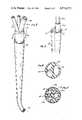
- FIG. 1is a perspective view of the RF welding device having portions broken away and in phantom for illustration and clarification and shown with a mandrel and IV tube in position for the welding operation;
- FIG. 2is a perspective view of the multi-lumen catheter with attached IV tubes
- FIG. 3is a perspective view of the multi-lumen catheter showing an IV tube and mandrel in position for the welding of the IV tube to the catheter;
- FIG. 4is a cross-sectional view of the catheter prior to attachment of the IV tubes as seen along the line 4--4 in FIG. 2;
- FIG. 5is a cross-sectional view of the catheter after attachment of the IV tubes as seen along the line 4--4 in FIG. 2;
- FIG. 6is a cross-sectional view of the area of attachment between the IV tube and the catheter;
- FIG. 7ais a side view of the dielectric collet along the line 7a--7a of FIG. 8;
- FIG. 7bis a side view of the metal collet with portions shown in phantom for illustration and clarification;
- FIG. 7cis a side view of the metal adapter of the present invention with portions shown in phantom for illustration and clarification;
- FIG. 8is a top view of the dielectric collet of the present invention.
- FIG. 9is a top view of the metal collet of the present invention.
- FIG. 1a welding device generally indicated by the numeral 10 which incorporates the principals of the present invention.
- a metal adapter 12is mounted on a support 76.
- metal collet 14 and dielectric collet 16which are operatively associated with each other to clampingly engage and hold the catheter 18 within dielectric collet 16.
- the interrelation of metal adapter 12, metal collet 14 and dielectric collet 16can best be appreciated by reference to FIGS. 7a, 7b and 7c, which, taken together, show an exploded arrangement of these elements of the present invention.
- the dielectric collet 16nests within metal collet 14, and both are operatively associated with the metal adapter 12 in a manner to be subsequently discussed in greater detail.
- a collar 32 having a peripheral groove 34is attached to extension 56 of metal collet 14.
- a semi-circular shaped band 36is connected with collar 32 by a screw 38a and a second screw 38b which are generally parallel to each other. Screw 38a and 38b are tightened in a manner that grips extension 56 of metal collet 14 between collar 32 and band 36 to prevent relative motion between collar 32 and extension 56.
- a pivot arm 42is rotatably mounted on support 76 by a hinge pin 44.
- Actuator arm 46is rigidly attached to pivot arm 42 and operatively coupled to piston 48 to rotate pivot arm 42 around hinge pin 44 in accordance with movement of piston 48.
- a pin 40is mounted on pivot arm 42 and is slidably received within the slot 34 of collar 32 to raise and lower metal collet 14 along a line generally indicated by directional arrow 74.
- dielectric collet 16comprises a plurality of resilient members 50 which are separated from each other by the slots 52 and which are integrally attached one with each other at the bottom 68 of dielectric collet 16.
- Each resilient member 50further comprises an end portion 54 which is dimensioned and adapted to cooperate with the other resilient members 50 of dielectric collet 16 to clampingly engage catheter 18.
- Dielectric collet 16is also formed with a pathway 70 so that as the end portions 54 of resilient member 50 grasp a certain part of the catheter 18, the remainder of catheter 18 can extend on through pathway 70.
- dielectric collet 16is made of a material known in the relevant art as acetal. It should be appreciated, however, that any dielectric material having sufficient strength and resilience to clampingly engage the catheter 18 is sufficient for the purposes of the present invention.
- FIG. 9 and FIG. 7brespectively show a top view and a side view of the metal collet 14.
- metal collet 14comprises a plurality of resilient fingers 58 which are separated from each other by the slots 60 and are integrally joined to the extension portion 56 of metal collet 14 in a manner that permits the cooperation of resilient fingers to clampingly engage upon an object.
- each of the resilient fingers 58is formed with a flange portion 72 which extends outwardly from resilient fingers 58 and is tapered or flared for a purpose to be subsequently discussed.
- passageway 64Formed throughout the longitudinal length of metal collet 14 is a passageway 64 in the region where the resilient fingers 58 are located and a passageway 66 in the region associated with extension 56. Passageway 64 and passageway 66 are dimensioned so that the diameter of the passageway 64 is greater than the diameter of passageway 66. As best seen in FIG. 7b, this change in dimension of passageway 64 creates a base 62 within the metal collet 14. As can be appreciated by reference to FIGS. 1, 7a and 7b, the dielectric collet 16 is dimensioned to nest within the passageway 64 of metal collet 14 with bottom 68 of dielectric collet 16 resting against base 62 of the metal collet 14.
- dielectric collet 16In this configuration the top portion of dielectric collet 16 is flush with the top of metal collet 14. It should now be appreciated that a circumferencial force acting upon metal collet 14 will cause resilient fingers 58 to merge and reduce the diameter of passageway 64 in the region where resilient fingers 58 are located. Consequently, metal collet 14 engages resilient members 50 of dielectric collet 16 in a manner that causes resilient members 50 to merge and reduce the diameter of pathway 70 in the area where end portions 54 of dielectric collet 16 are located.
- a metal adapter 12, as shown in FIG. 7cis formed with a bore 78 having a tapered region generally designated A in FIG. 7c.
- dielectric collet 16 and metal collet 14are cooperatively positioned as previously discussed and that the combination of dielectric collet 16 and metal collet 14 are dimensioned to be received into the bore 78 of adapter 12.
- the metal collet 14is positioned within bore 78 of adapter 12, it should be appreciated that the tapered portion of the flanges 72 on metal collet 14 engage with tapered region A of the adapter 12.
- adapter 12 and metal collet 14are made of a beryllium copper alloy.
- adapter 12may also be made of cold rolled steel and the metal collet 14 may be made of a heat treated spring steel.
- metal collet 16 and adapter 12provide an electrical ground and that metal collet 14 be of sufficient strength and resilience to perform the function of clampingly engaging an object, such as dielectric collet 16, when the object is placed in passageway 64 of the metal collet 14.
- the materials for adapter 12 and metal collet 14be of sufficient strength to resist continued operation in a manufacturing environment.
- FIG. 4shows a typical cross section of a multilumen catheter 18 having eliptical shaped lumens 24 before the catheter 18 is attached in fluid communication with an IV tube 20a.
- FIG. 3shows the association of an IV tube 20a with a lumen 24 of catheter 18 during the welding procedure.
- a mandrel 22ais inserted into the passageway of IV tube 20a.
- the combination of IV tube 20a and mandrel 22ais then inserted into a lumen 24 of catheter 18.
- mandrels 22b and care respectively inserted into IV tubes 20b and c and separately inserted into lumens 24 of catheter 18.
- IV tubes 20a, b and care discussed here, it must be appreciated that more or fewer IV tubes 20 can be used depending only on the number of lumens 24.
- the mandrels 22a, b and care made of a beryllium copper alloy. Spring steel, sometimes commonly referred to by those skilled in the art as “piano wire” may, however, also be used for mandrels 22a, b and c.
- a generator 30may be of any suitable construction well known in the art which is designed to produce high frequency power for welding plastics and other materials.
- generator 30is connected through a line 28 to connector 26a in a manner well known in the art.
- the generator 30is then activated to provide RF energy to the mandrel 22a for welding and reforming the IV tube 20a to the side wall inner surface of a respective lumen 24 in the catheter 18.
- line 28can then be connected to mandrels 22b and c and generator 30 activated to weld and reform IV tubes 20b and c with the respective lumens 24.
- welding device 10is particularly useful for work with IV tubes 20a, b or c and catheters 18 which are made of polyurethane.
- a barium-filled polyurethane to provide the radiopacity characteristic of many preferred cathetersis acceptable for use with the welding device 10.
- the metal collet 14can be eliminated from the welding device 10 without affecting the utility or operation of the welding device 10.
- the dielectric collet 16is formed to function like metal collet 14 of the preferred embodiment and made operable in direct association with the adapter 12 to clampingly engage the catheter 18.
- metal collet 14is included in the preferred embodiment for the purpose of providing a more rugged device which is capable of withstanding the repetitive operations likely to be encountered in a manufacturing process.
- the necessity for metal collet 14is, in part, caused by material limitations.
- the acetal material preferably used in the manufacture of dielectric collet 16is not suited for the repetitive and continuous operation envisioned in the manufacturing process.
- Dielectric collet 16when nested in passageway 64 of metal collet 14 as intended in the preferred embodiment is not subjected to the stresses and loads which would cause it to wear out early. Regardless, the utility of welding device 10 is dependant upon an electrical connection wherein the IV tube 20a and the catheter 18, in combination with a dielectric, separate mandrel 22 from an electrical ground. According to the present invention, metal collet 14 and adapter 12 provide the ground. As easily understood by those skilled in the pertinent art, any ground will do. Thus metal adapter 12 alone, as described for an alternate embodiment, will suffice and metal collet 14 could, in fact, be eliminated.
- FIG. 4shows a typical cross section of catheter 18 having eliptical shaped lumens 24.
- IV tubes 20a, b and ctypically have generally circular cross-sections.
- IV tubes 20a, b and care incompatible for a directly conforming fit with the eliptical cross-section of lumens 24.
- the compressive action of dielectric collet 16 and the subsequent reforming and welding operation mentioned abovecreate a bonded conformity between the outside surfaces of IV tubes 20a, b and c and the respective lumens 24.
- the resultis a continuous and integral bond between the IV tubes 20a, b and c and the lumens 24 of catheter 18. Furthermore, this bond is continuous throughout the region B indicated in FIGS. 2 and 3.
- the catheter 18 and the attached IV tubes 20a, b and cprovide a device of unitary construction which is a structural continuum at the juncture of tube 20 and lumen 24.
- IV tubes 20a, b and chaving thicker walls than would otherwise be possible. Indeed, in the preferred embodiment, wall thicknesses from 0.020 inches to 0.030 inches are not uncommon. Of course, walls thinner than 0.020 inches are also suitable for the present invention and walls thicker than 0.030 inches may be used depending on the compressive strength of the device 10 and the amount of RF power supplied by generator 30.
- IV tube 20is formed with a chamfered tip 80 at the end of IV tube 20 that is inserted into and welded to catheter 18.
- the chamfered tip 80so positioned, permits entry of a guidewire (not shown) between lumen 24 and IV tube 20 without hanging up the guidewire (not shown) at the juncture of the end of IV tube 20a with the lumen 24.
- the chamfered tip 80also helps prevent air bubble immobilization and fluid stagnation areas at the juncture.
- each lumen 24may be preformed to establish a step 82 within the lumen 24 against which the chamfered tip 80 of IV tube 20 can be positioned.
- the step 82permits an unobstructed transition for passage of the guidewire (not shown) from lumen 24 onto the chamfered surface of chamfered tip 80 and into IV tube 20.
- Step 82can be preformed by inserting into a lumen 24 a mandrel (not shown) having a cross-sectional area that is substantially equivalent to the cross-sectional area of lumen 24. Sufficient RF energy from generator 30 is then supplied to the mandrel to reform lumen 24 and shape step 82.
- a suitable material for the catheter 18is a barium-filled polyurethane.
- IV tubes 20a, b and care also made of a polyurethane material.
- the use of the same material throughout the catheter 18 and IV tube 20 combinationobviates any differences in strength, durability or compatability which may occur when dissimilar materials are used.
- the expressed preference for the present inventionis the use of a polyurethane material, other materials which are well known in the art and suitable for an RF welding operation may be used. In fact, dependent only on the desires of the manufacturer, the catheter 18 and IV tubes 20 may even be of dissimilar materials.
- a mandrel 22a having electrical conductive propertiessuch as beryllium copper alloy, is inserted into the passageway of an IV tube 20a.
- the mandrel 22a and IV tube 20a combinationis then inserted into a lumen 24 of a catheter 18.
- mandrels 22b and care respectively inserted into IV tubes 20b and c and these combinations are positioned into lumens 24 of catheter 18.
- the proper operation of welding device 10is not dependent on cross-sectional conformity between the IV tube 20a, b and c and the lumens 24.
- IV tubes 20 and mandrels 22With the catheter 18, IV tubes 20 and mandrels 22 positioned within the welding device 10 as shown in FIG. 1 and after welding device 10 has been operated to compress the dielectric collet 16 onto catheter 18, the exposed end of mandrel 22a opposite from the end which is associated with catheter 18 is electrically connected to a connector 26a.
- Connector 26awhich is in electrical contact with generator 30 through line 28, provides means for supplying RF energy from generator 30 to mandrel 22a.
- the initial compatability or incompatability of configuration between the IV tube and the shape of lumen 24becomes less important.
- a beneficial effect of this factis that thicker walled IV tubes 20 can be welded into lumen 24 with less power required from generator 30. It is not uncommon to consider operation of the welding device 10 within a range of power supplied to mandrel 22 of from 300 to 1,000 watts.
- the power supply 30is energized and energy is passed along mandrel 22a to weld IV tube 20a to catheter 18. Sequentially, energy from generator 30 is applied to mandrels 22b and c to weld IV tubes 20b and c to catheter 18. After the welding operation is completed, the catheter 18 and IV tubes 20a, b and c are allowed to cool for a period of time. The welding device 10 is then operated to move the metal collet 14 in a direction opposite to directional arrow 74. This releases the grip or clamping effect of dielectric collet 16 on catheter 18. The catheter 18 and IV tube 20a combination can then be removed from welding device 10 and mandrels 22a, b and c can be removed from IV tubes 20a, b and c.
- Catheter 18can be dimensioned for adaptability and use as a venous catheter.
- the unitary construction for catheter 18, as described aboveprovides for multiple fluid passageways defined by the individual proximal IV tubes 20 and their associated lumens 24.
- the end of each individual IV tube 20 opposite from the catheter 18can be specially adapted for connection with a particular fluid source (not shown).
- the various fluid sources suitable for use with catheter 18include IV pumps, IV controllers, IV bottles, syringes, and other specialized fluid containers. Regardless of the particular fluid source used, catheter 18 when properly positioned into the vein of a patient and the IV tubes 20 associated with catheter 18 provide an effective means for infusing medical solutions to the patient.
Landscapes
- Engineering & Computer Science (AREA)
- Mechanical Engineering (AREA)
- Health & Medical Sciences (AREA)
- Life Sciences & Earth Sciences (AREA)
- Anesthesiology (AREA)
- Hematology (AREA)
- Biophysics (AREA)
- Pulmonology (AREA)
- Physics & Mathematics (AREA)
- Biomedical Technology (AREA)
- Heart & Thoracic Surgery (AREA)
- Electromagnetism (AREA)
- Animal Behavior & Ethology (AREA)
- General Health & Medical Sciences (AREA)
- Public Health (AREA)
- Veterinary Medicine (AREA)
- Media Introduction/Drainage Providing Device (AREA)
- Lining Or Joining Of Plastics Or The Like (AREA)
- Infusion, Injection, And Reservoir Apparatuses (AREA)
Abstract
Description
Claims (18)
Priority Applications (6)
| Application Number | Priority Date | Filing Date | Title |
|---|---|---|---|
| US06/607,329US4574173A (en) | 1984-05-04 | 1984-05-04 | Device for RF welding an IV tube to a catheter lumen |
| CA000479284ACA1217531A (en) | 1984-05-04 | 1985-04-16 | Device for r.f. welding an iv tube to a catheter lumen |
| DE8585303052TDE3571578D1 (en) | 1984-05-04 | 1985-04-30 | Device for r.f. welding an i.v. tube to a catheter lumen |
| EP85303052AEP0161862B1 (en) | 1984-05-04 | 1985-04-30 | Device for r.f. welding an i.v. tube to a catheter lumen |
| JP60094571AJPS60244527A (en) | 1984-05-04 | 1985-05-01 | Device for rf-welding iv pipe to polylacunar catheter |
| AU41940/85AAU569010B2 (en) | 1984-05-04 | 1985-05-03 | R.f. welding |
Applications Claiming Priority (1)
| Application Number | Priority Date | Filing Date | Title |
|---|---|---|---|
| US06/607,329US4574173A (en) | 1984-05-04 | 1984-05-04 | Device for RF welding an IV tube to a catheter lumen |
Publications (1)
| Publication Number | Publication Date |
|---|---|
| US4574173Atrue US4574173A (en) | 1986-03-04 |
Family
ID=24431812
Family Applications (1)
| Application Number | Title | Priority Date | Filing Date |
|---|---|---|---|
| US06/607,329Expired - Fee RelatedUS4574173A (en) | 1984-05-04 | 1984-05-04 | Device for RF welding an IV tube to a catheter lumen |
Country Status (6)
| Country | Link |
|---|---|
| US (1) | US4574173A (en) |
| EP (1) | EP0161862B1 (en) |
| JP (1) | JPS60244527A (en) |
| AU (1) | AU569010B2 (en) |
| CA (1) | CA1217531A (en) |
| DE (1) | DE3571578D1 (en) |
Cited By (51)
| Publication number | Priority date | Publication date | Assignee | Title |
|---|---|---|---|---|
| US4755649A (en)* | 1986-07-16 | 1988-07-05 | Becton Dickinson And Company | Apparatus for compression welding of adapter and flanged catheter |
| US4886506A (en)* | 1986-12-23 | 1989-12-12 | Baxter Travenol Laboratories, Inc. | Soft tip catheter |
| US4954678A (en)* | 1988-06-06 | 1990-09-04 | Engineering & Research Associates, Inc. | Annular RF sealer and method |
| US4990138A (en)* | 1989-07-18 | 1991-02-05 | Baxter International Inc. | Catheter apparatus, and compositions useful for producing same |
| US5160396A (en)* | 1991-02-11 | 1992-11-03 | Engineering & Research Associates, Inc. | Low thermal inertia heater |
| US5308325A (en)* | 1991-01-28 | 1994-05-03 | Corpak, Inc. | Retention balloon for percutaneous catheter |
| US5427645A (en)* | 1991-12-09 | 1995-06-27 | W. R. Grace & Co.-Conn. | Apparatus and method for radio frequency sealing thermoplastic films together |
| US5439444A (en)* | 1991-01-28 | 1995-08-08 | Corpak, Inc. | Pre-formed member for percutaneous catheter |
| US5712044A (en)* | 1993-08-06 | 1998-01-27 | Minnesota Mining And Manufacturing Company | Medical device assemblies constructed from multilayered films |
| US5738923A (en)* | 1995-05-16 | 1998-04-14 | Minnesota Mining And Manufacturing Company | Medical tubing and assemblies |
| US5766400A (en)* | 1996-08-27 | 1998-06-16 | Liteliner, L.L.C. | Method of producing prefabricated multi layered flexible products and products having improved sealing profiles resulting therefrom |
| US5789725A (en)* | 1996-01-15 | 1998-08-04 | The Whitaker Corporation | Radio frequency heat sealing of cable assemblies |
| US6036654A (en)* | 1994-09-23 | 2000-03-14 | Baxter International Inc. | Multi-lumen, multi-parameter catheter |
| US6036811A (en)* | 1996-08-27 | 2000-03-14 | Liteliner International Holdings, Co., Llc | Leakproof seams for non-containable waterproof/breathable fabric composites |
| US6171431B1 (en) | 1996-08-27 | 2001-01-09 | Joseph E. Gallagher, Jr. | Welded fabric seams with inner and outer tabs |
| US6227200B1 (en) | 1998-09-21 | 2001-05-08 | Ballard Medical Products | Respiratory suction catheter apparatus |
| US6543451B1 (en) | 1999-12-23 | 2003-04-08 | Kimberly-Clark Worldwide, Inc. | Endotracheal catheter and manifold assembly with improved seal and valve |
| US6588427B1 (en) | 2002-02-25 | 2003-07-08 | Kimberly-Clark Worldwide, Inc. | Heat and moisture exchanger adapter to closed suction catheter assembly and system having improved catheter cleaning |
| US20030163082A1 (en)* | 2002-02-26 | 2003-08-28 | Mertens Steven P. | Lumen weld |
| US20040004311A1 (en)* | 2002-02-26 | 2004-01-08 | Scimed Life Systems, Inc. | Tacking method and apparatus |
| US20040019313A1 (en)* | 2002-07-19 | 2004-01-29 | Childers Robert W. | Systems, methods and apparatuses for pumping cassette-based therapies |
| US20040116899A1 (en)* | 2002-12-16 | 2004-06-17 | Shaughnessy Michael C. | Bolus for non-occluding high flow enteral feeding tube |
| US6769430B1 (en) | 2000-10-31 | 2004-08-03 | Kimberly-Clark Worldwide, Inc. | Heat and moisture exchanger adaptor for closed suction catheter assembly and system containing the same |
| US20050144696A1 (en)* | 2002-08-29 | 2005-07-07 | Lack Craig D. | Adjustably insulative construct |
| US20050159712A1 (en)* | 2000-07-12 | 2005-07-21 | Erik Andersen | Catheter having a tip with an elongated collar |
| US20050182355A1 (en)* | 2002-01-03 | 2005-08-18 | Tuan Bui | Method and apparatus for providing medical treatment therapy based on calculated demand |
| US20050261666A1 (en)* | 2004-05-18 | 2005-11-24 | Blane Larson | Medical devices and methods of making the same |
| US7021313B1 (en) | 1998-09-21 | 2006-04-04 | Ballard Medical Products | Respiratory suction catheter apparatus with improved valve and collar |
| US7152603B1 (en) | 1999-12-13 | 2006-12-26 | Kimberly-Clark Worldwide, Inc. | Endotracheal catheter and manifold assembly with improved valve |
| US20060289112A1 (en)* | 2005-06-23 | 2006-12-28 | Holman Thomas J | Methods of making medical devices |
| US20080004571A1 (en)* | 2006-06-28 | 2008-01-03 | Abbott Laboratories | Expandable introducer sheath |
| US20080004569A1 (en)* | 2006-06-28 | 2008-01-03 | Abbott Laboratories | Expandable Introducer Sheath to Preserve Guidewire Access |
| US20080077173A1 (en)* | 2006-09-25 | 2008-03-27 | Boston Scientific Scimed, Inc. | Designs for balloon welds |
| US20080200869A1 (en)* | 2007-02-15 | 2008-08-21 | Baxter International Inc. | Dialysis system with efficient battery back-up |
| US20080200865A1 (en)* | 2007-02-15 | 2008-08-21 | Baxter International Inc. | Dialysis system having optical flowrate detection |
| US20080200868A1 (en)* | 2007-02-15 | 2008-08-21 | One Baxter Parkway | Dialysis system having video display with ambient light adjustment |
| US20100130937A1 (en)* | 2005-06-30 | 2010-05-27 | Abbott Vascular Inc. | Introducer sheath and methods of making |
| US20100130936A1 (en)* | 2005-06-30 | 2010-05-27 | Abbott Vascular Inc. | Introducer sheath and methods of making |
| US20100130939A1 (en)* | 2005-06-30 | 2010-05-27 | Abbott Vascular Inc. | Introducer sheath and methods of making |
| US7731689B2 (en) | 2007-02-15 | 2010-06-08 | Baxter International Inc. | Dialysis system having inductive heating |
| US20100198160A1 (en)* | 2006-06-28 | 2010-08-05 | Abbott Vascular Inc. | Expandable Introducer Sheaths and Methods for Manufacture and Use |
| US20100198159A1 (en)* | 2006-06-28 | 2010-08-05 | Abbott Vascular Inc. | Expandable introducer sheath to preserve guidewire access |
| US7976518B2 (en) | 2005-01-13 | 2011-07-12 | Corpak Medsystems, Inc. | Tubing assembly and signal generator placement control device and method for use with catheter guidance systems |
| US8323231B2 (en) | 2000-02-10 | 2012-12-04 | Baxter International, Inc. | Method and apparatus for monitoring and controlling peritoneal dialysis therapy |
| US8558964B2 (en) | 2007-02-15 | 2013-10-15 | Baxter International Inc. | Dialysis system having display with electromagnetic compliance (“EMC”) seal |
| US9028441B2 (en) | 2011-09-08 | 2015-05-12 | Corpak Medsystems, Inc. | Apparatus and method used with guidance system for feeding and suctioning |
| US9168359B2 (en) | 2005-06-30 | 2015-10-27 | Abbott Laboratories | Modular introducer and exchange sheath |
| US9352118B2 (en) | 2005-06-30 | 2016-05-31 | Abbott Laboratories | Modular introducer and exchange sheath |
| US9889275B2 (en) | 2006-06-28 | 2018-02-13 | Abbott Laboratories | Expandable introducer sheath to preserve guidewire access |
| US11179516B2 (en) | 2017-06-22 | 2021-11-23 | Baxter International Inc. | Systems and methods for incorporating patient pressure into medical fluid delivery |
| WO2024046865A1 (en)* | 2022-08-30 | 2024-03-07 | Biotronik Ag | Heat shrink tubing-free catheter connections |
Families Citing this family (4)
| Publication number | Priority date | Publication date | Assignee | Title |
|---|---|---|---|---|
| US5178803A (en)* | 1987-06-25 | 1993-01-12 | Terumo Kabushiki Kaisha | Method of manufacturing a multi-luminal catheter, and multi-luminal catheter assembly |
| KR910002210B1 (en)* | 1987-06-25 | 1991-04-08 | 데루모가부시끼가이샤 | Plural lumen catheter, Plural lumen catheter assembly and method of manufacturing the same |
| EP2420286A1 (en)* | 2010-08-18 | 2012-02-22 | Fresenius Kabi Deutschland GmbH | Method and device for sterile connection of hoses |
| DE102018207642A1 (en)* | 2018-05-16 | 2019-11-21 | B. Braun Melsungen Ag | Catheter assembly and method of making such a catheter assembly |
Citations (30)
| Publication number | Priority date | Publication date | Assignee | Title |
|---|---|---|---|---|
| US399985A (en)* | 1889-03-19 | good willie | ||
| US2561569A (en)* | 1947-01-10 | 1951-07-24 | Wardlyn Corp | Method of making catheters |
| US2775068A (en)* | 1954-03-22 | 1956-12-25 | Western Electric Co | Metal to glass sealing fixture |
| US2876358A (en)* | 1957-04-18 | 1959-03-03 | Bradley Container Corp | Method of and apparatus for treating surfaces of thermoplastic containers by corona discharge |
| US3064653A (en)* | 1959-06-04 | 1962-11-20 | Baxter Don Inc | Catheter for an administration set |
| US3174890A (en)* | 1961-07-10 | 1965-03-23 | Baxter Laboratories Inc | Methods of preparing surgical cannula |
| US3293402A (en)* | 1963-08-05 | 1966-12-20 | Omark Industries Inc | Pneumatic operated welding stud holder |
| US3322590A (en)* | 1964-03-09 | 1967-05-30 | Plastronics Inc | Method for making a sealed connection between a tube and a container |
| US3469579A (en)* | 1967-05-05 | 1969-09-30 | Becton Dickinson Co | Catheter needle |
| US3625793A (en)* | 1969-09-23 | 1971-12-07 | David S Sheridan | Balloon-type catheters and method of manufacture |
| US3720210A (en)* | 1971-03-03 | 1973-03-13 | Baxter Laboratories Inc | Indwelling catheter device |
| US3817389A (en)* | 1973-01-15 | 1974-06-18 | Sherwood Medical Ind Inc | Filter device in tubular fitting for medical injection equipment and the like |
| US3959058A (en)* | 1974-11-08 | 1976-05-25 | Plastronics, Inc. | Method and apparatus for butt-welding tubular plastic members to each other |
| US3976529A (en)* | 1973-01-15 | 1976-08-24 | Sherwood Medical Industries Inc. | Method of sealing filter in tubular fitting for medical injection equipment and the like |
| US4050667A (en)* | 1975-11-26 | 1977-09-27 | Will Ross, Inc. | Tube mold |
| US4072146A (en)* | 1976-09-08 | 1978-02-07 | Howes Randolph M | Venous catheter device |
| US4072153A (en)* | 1976-03-03 | 1978-02-07 | Swartz William H | Post hysterectomy fluid drainage tube |
| US4133544A (en)* | 1977-10-25 | 1979-01-09 | Bryant Grinder | Replaceable collet in double diaphragm chuck |
| US4210479A (en)* | 1978-06-14 | 1980-07-01 | Baxter Travenol Laboratories, Inc. | Method for bonding a plastic tubing to a metal needle and the needle assembly formed thereby |
| US4214593A (en)* | 1978-09-18 | 1980-07-29 | Mallinckrodt, Inc. | Esophageal pressure monitoring device |
| US4248224A (en)* | 1978-08-01 | 1981-02-03 | Jones James W | Double venous cannula |
| US4268338A (en)* | 1979-08-20 | 1981-05-19 | Peterson Electronic Die Co. | Method and apparatus for RF sealing of thermoplastic layers |
| US4309994A (en)* | 1980-02-25 | 1982-01-12 | Grunwald Ronald P | Cardiovascular cannula |
| US4354495A (en)* | 1980-10-30 | 1982-10-19 | Sherwood Medical Industries Inc. | Method of connecting plastic tube to a plastic part |
| US4364394A (en)* | 1980-11-24 | 1982-12-21 | Wilkinson Lawrence H | Combined sump drainage and irrigation device |
| US4384186A (en)* | 1981-07-23 | 1983-05-17 | William R. Burt | Electrode sealing system for thermoplastic tube |
| US4398910A (en)* | 1981-02-26 | 1983-08-16 | Blake L W | Wound drain catheter |
| US4405313A (en)* | 1982-01-29 | 1983-09-20 | Sisley James R | Figure-eight, dual-lumen catheter and method of using |
| US4406656A (en)* | 1981-06-01 | 1983-09-27 | Brack Gillium Hattler | Venous catheter having collapsible multi-lumens |
| US4419095A (en)* | 1980-05-14 | 1983-12-06 | Shiley, Inc. | Cannula with radiopaque tip |
Family Cites Families (6)
| Publication number | Priority date | Publication date | Assignee | Title |
|---|---|---|---|---|
| US2816596A (en)* | 1955-08-09 | 1957-12-17 | Fenwal Lab Inc | Dielectric heat sealing method and apparatus |
| US3558397A (en)* | 1968-02-15 | 1971-01-26 | Plastronics Inc | Method of making a tube-to-bag connection |
| US3706620A (en)* | 1970-03-13 | 1972-12-19 | Ethylox Products Inc | Method and apparatus for forming the end of a plastic tube and sealing the tube within a flexible container |
| GB1581955A (en)* | 1977-08-25 | 1980-12-31 | Matburn Holdings Ltd | Catheter |
| US4251310A (en)* | 1977-11-25 | 1981-02-17 | Baxter Travenol Laboratories, Inc. | Method for rebonding tubing elements used in needle assemblies |
| CA1257822A (en)* | 1984-05-04 | 1989-07-25 | Laurence M. Bennett | Multilumen catheter and associated i.v. tubing |
- 1984
- 1984-05-04USUS06/607,329patent/US4574173A/ennot_activeExpired - Fee Related
- 1985
- 1985-04-16CACA000479284Apatent/CA1217531A/ennot_activeExpired
- 1985-04-30DEDE8585303052Tpatent/DE3571578D1/ennot_activeExpired
- 1985-04-30EPEP85303052Apatent/EP0161862B1/ennot_activeExpired
- 1985-05-01JPJP60094571Apatent/JPS60244527A/enactiveGranted
- 1985-05-03AUAU41940/85Apatent/AU569010B2/ennot_activeCeased
Patent Citations (30)
| Publication number | Priority date | Publication date | Assignee | Title |
|---|---|---|---|---|
| US399985A (en)* | 1889-03-19 | good willie | ||
| US2561569A (en)* | 1947-01-10 | 1951-07-24 | Wardlyn Corp | Method of making catheters |
| US2775068A (en)* | 1954-03-22 | 1956-12-25 | Western Electric Co | Metal to glass sealing fixture |
| US2876358A (en)* | 1957-04-18 | 1959-03-03 | Bradley Container Corp | Method of and apparatus for treating surfaces of thermoplastic containers by corona discharge |
| US3064653A (en)* | 1959-06-04 | 1962-11-20 | Baxter Don Inc | Catheter for an administration set |
| US3174890A (en)* | 1961-07-10 | 1965-03-23 | Baxter Laboratories Inc | Methods of preparing surgical cannula |
| US3293402A (en)* | 1963-08-05 | 1966-12-20 | Omark Industries Inc | Pneumatic operated welding stud holder |
| US3322590A (en)* | 1964-03-09 | 1967-05-30 | Plastronics Inc | Method for making a sealed connection between a tube and a container |
| US3469579A (en)* | 1967-05-05 | 1969-09-30 | Becton Dickinson Co | Catheter needle |
| US3625793A (en)* | 1969-09-23 | 1971-12-07 | David S Sheridan | Balloon-type catheters and method of manufacture |
| US3720210A (en)* | 1971-03-03 | 1973-03-13 | Baxter Laboratories Inc | Indwelling catheter device |
| US3817389A (en)* | 1973-01-15 | 1974-06-18 | Sherwood Medical Ind Inc | Filter device in tubular fitting for medical injection equipment and the like |
| US3976529A (en)* | 1973-01-15 | 1976-08-24 | Sherwood Medical Industries Inc. | Method of sealing filter in tubular fitting for medical injection equipment and the like |
| US3959058A (en)* | 1974-11-08 | 1976-05-25 | Plastronics, Inc. | Method and apparatus for butt-welding tubular plastic members to each other |
| US4050667A (en)* | 1975-11-26 | 1977-09-27 | Will Ross, Inc. | Tube mold |
| US4072153A (en)* | 1976-03-03 | 1978-02-07 | Swartz William H | Post hysterectomy fluid drainage tube |
| US4072146A (en)* | 1976-09-08 | 1978-02-07 | Howes Randolph M | Venous catheter device |
| US4133544A (en)* | 1977-10-25 | 1979-01-09 | Bryant Grinder | Replaceable collet in double diaphragm chuck |
| US4210479A (en)* | 1978-06-14 | 1980-07-01 | Baxter Travenol Laboratories, Inc. | Method for bonding a plastic tubing to a metal needle and the needle assembly formed thereby |
| US4248224A (en)* | 1978-08-01 | 1981-02-03 | Jones James W | Double venous cannula |
| US4214593A (en)* | 1978-09-18 | 1980-07-29 | Mallinckrodt, Inc. | Esophageal pressure monitoring device |
| US4268338A (en)* | 1979-08-20 | 1981-05-19 | Peterson Electronic Die Co. | Method and apparatus for RF sealing of thermoplastic layers |
| US4309994A (en)* | 1980-02-25 | 1982-01-12 | Grunwald Ronald P | Cardiovascular cannula |
| US4419095A (en)* | 1980-05-14 | 1983-12-06 | Shiley, Inc. | Cannula with radiopaque tip |
| US4354495A (en)* | 1980-10-30 | 1982-10-19 | Sherwood Medical Industries Inc. | Method of connecting plastic tube to a plastic part |
| US4364394A (en)* | 1980-11-24 | 1982-12-21 | Wilkinson Lawrence H | Combined sump drainage and irrigation device |
| US4398910A (en)* | 1981-02-26 | 1983-08-16 | Blake L W | Wound drain catheter |
| US4406656A (en)* | 1981-06-01 | 1983-09-27 | Brack Gillium Hattler | Venous catheter having collapsible multi-lumens |
| US4384186A (en)* | 1981-07-23 | 1983-05-17 | William R. Burt | Electrode sealing system for thermoplastic tube |
| US4405313A (en)* | 1982-01-29 | 1983-09-20 | Sisley James R | Figure-eight, dual-lumen catheter and method of using |
Cited By (88)
| Publication number | Priority date | Publication date | Assignee | Title |
|---|---|---|---|---|
| US4755649A (en)* | 1986-07-16 | 1988-07-05 | Becton Dickinson And Company | Apparatus for compression welding of adapter and flanged catheter |
| US4886506A (en)* | 1986-12-23 | 1989-12-12 | Baxter Travenol Laboratories, Inc. | Soft tip catheter |
| US4954678A (en)* | 1988-06-06 | 1990-09-04 | Engineering & Research Associates, Inc. | Annular RF sealer and method |
| US4990138A (en)* | 1989-07-18 | 1991-02-05 | Baxter International Inc. | Catheter apparatus, and compositions useful for producing same |
| US5308325A (en)* | 1991-01-28 | 1994-05-03 | Corpak, Inc. | Retention balloon for percutaneous catheter |
| US5439444A (en)* | 1991-01-28 | 1995-08-08 | Corpak, Inc. | Pre-formed member for percutaneous catheter |
| US5306377A (en)* | 1991-02-11 | 1994-04-26 | Engineering & Research Associates, Inc. | Mold including a low thermal inertia heater and method of using same |
| US5160396A (en)* | 1991-02-11 | 1992-11-03 | Engineering & Research Associates, Inc. | Low thermal inertia heater |
| US5427645A (en)* | 1991-12-09 | 1995-06-27 | W. R. Grace & Co.-Conn. | Apparatus and method for radio frequency sealing thermoplastic films together |
| US5712044A (en)* | 1993-08-06 | 1998-01-27 | Minnesota Mining And Manufacturing Company | Medical device assemblies constructed from multilayered films |
| US5766744A (en)* | 1993-08-06 | 1998-06-16 | Minnesota Mining And Manufacturing Company | Chlorine-free multilayered films |
| US6045648A (en)* | 1993-08-06 | 2000-04-04 | Minnesta Mining And Manufacturing Company | Thermoset adhesive having susceptor particles therein |
| US6036654A (en)* | 1994-09-23 | 2000-03-14 | Baxter International Inc. | Multi-lumen, multi-parameter catheter |
| US5738923A (en)* | 1995-05-16 | 1998-04-14 | Minnesota Mining And Manufacturing Company | Medical tubing and assemblies |
| US5792988A (en)* | 1996-01-15 | 1998-08-11 | The Whitaker Corporation | Radio frequency heat sealing of cable assemblies |
| US5789725A (en)* | 1996-01-15 | 1998-08-04 | The Whitaker Corporation | Radio frequency heat sealing of cable assemblies |
| US6036811A (en)* | 1996-08-27 | 2000-03-14 | Liteliner International Holdings, Co., Llc | Leakproof seams for non-containable waterproof/breathable fabric composites |
| US6171431B1 (en) | 1996-08-27 | 2001-01-09 | Joseph E. Gallagher, Jr. | Welded fabric seams with inner and outer tabs |
| US5766400A (en)* | 1996-08-27 | 1998-06-16 | Liteliner, L.L.C. | Method of producing prefabricated multi layered flexible products and products having improved sealing profiles resulting therefrom |
| US6227200B1 (en) | 1998-09-21 | 2001-05-08 | Ballard Medical Products | Respiratory suction catheter apparatus |
| US7021313B1 (en) | 1998-09-21 | 2006-04-04 | Ballard Medical Products | Respiratory suction catheter apparatus with improved valve and collar |
| US6805125B1 (en) | 1998-09-21 | 2004-10-19 | Ballard Medical Products | Respiratory suction catherer apparatus |
| US7152603B1 (en) | 1999-12-13 | 2006-12-26 | Kimberly-Clark Worldwide, Inc. | Endotracheal catheter and manifold assembly with improved valve |
| US6543451B1 (en) | 1999-12-23 | 2003-04-08 | Kimberly-Clark Worldwide, Inc. | Endotracheal catheter and manifold assembly with improved seal and valve |
| US8323231B2 (en) | 2000-02-10 | 2012-12-04 | Baxter International, Inc. | Method and apparatus for monitoring and controlling peritoneal dialysis therapy |
| US10322224B2 (en) | 2000-02-10 | 2019-06-18 | Baxter International Inc. | Apparatus and method for monitoring and controlling a peritoneal dialysis therapy |
| US9474842B2 (en) | 2000-02-10 | 2016-10-25 | Baxter International Inc. | Method and apparatus for monitoring and controlling peritoneal dialysis therapy |
| US7066914B2 (en) | 2000-07-12 | 2006-06-27 | Bird Products Corporation | Catheter having a tip with an elongated collar |
| US20050159712A1 (en)* | 2000-07-12 | 2005-07-21 | Erik Andersen | Catheter having a tip with an elongated collar |
| US20040255952A1 (en)* | 2000-10-31 | 2004-12-23 | Kimberly-Clark Worldwide, Inc. | Heat and moisture exchanger adaptor for closed suction catheter assembly and system containing the same |
| US6769430B1 (en) | 2000-10-31 | 2004-08-03 | Kimberly-Clark Worldwide, Inc. | Heat and moisture exchanger adaptor for closed suction catheter assembly and system containing the same |
| US7549419B2 (en) | 2000-10-31 | 2009-06-23 | Kimberly-Clark Worldwide, Inc. | Heat and moisture exchanger adaptor for closed suction catheter assembly and system containing the same |
| US20050182355A1 (en)* | 2002-01-03 | 2005-08-18 | Tuan Bui | Method and apparatus for providing medical treatment therapy based on calculated demand |
| US8545435B2 (en) | 2002-01-03 | 2013-10-01 | Baxter International, Inc. | Method and apparatus for providing medical treatment therapy based on calculated demand |
| US6588427B1 (en) | 2002-02-25 | 2003-07-08 | Kimberly-Clark Worldwide, Inc. | Heat and moisture exchanger adapter to closed suction catheter assembly and system having improved catheter cleaning |
| US20030163082A1 (en)* | 2002-02-26 | 2003-08-28 | Mertens Steven P. | Lumen weld |
| US7332689B2 (en) | 2002-02-26 | 2008-02-19 | Boston Scientific Scimed, Inc. | Tacking method and apparatus |
| US20040004311A1 (en)* | 2002-02-26 | 2004-01-08 | Scimed Life Systems, Inc. | Tacking method and apparatus |
| US7238164B2 (en) | 2002-07-19 | 2007-07-03 | Baxter International Inc. | Systems, methods and apparatuses for pumping cassette-based therapies |
| US20040019313A1 (en)* | 2002-07-19 | 2004-01-29 | Childers Robert W. | Systems, methods and apparatuses for pumping cassette-based therapies |
| US20050144696A1 (en)* | 2002-08-29 | 2005-07-07 | Lack Craig D. | Adjustably insulative construct |
| US20040116899A1 (en)* | 2002-12-16 | 2004-06-17 | Shaughnessy Michael C. | Bolus for non-occluding high flow enteral feeding tube |
| US20080103429A1 (en)* | 2002-12-31 | 2008-05-01 | Baxter International Inc. | Pumping material for cassette based dialysis and pumping mechanism using same |
| US20110218487A1 (en)* | 2002-12-31 | 2011-09-08 | Baxter International Inc. | Pumping material for cassette based dialysis and pumping mechanism using same |
| US7744554B2 (en) | 2002-12-31 | 2010-06-29 | Baxter International Inc. | Cassette alignment and integrity testing for dialysis systems |
| US20080132828A1 (en)* | 2002-12-31 | 2008-06-05 | Baxter International Inc. | Cassette alignment and integrity testing for dialysis systems |
| US8206338B2 (en) | 2002-12-31 | 2012-06-26 | Baxter International Inc. | Pumping systems for cassette-based dialysis |
| US7815624B2 (en) | 2004-05-18 | 2010-10-19 | Boston Scientific Scimed, Inc. | Medical devices and methods of making the same |
| US20050261666A1 (en)* | 2004-05-18 | 2005-11-24 | Blane Larson | Medical devices and methods of making the same |
| US9131956B2 (en) | 2005-01-13 | 2015-09-15 | Corpak Medsystems, Inc. | Tubing assembly and signal generator placement control device and method for use with catheter guidance systems |
| US10549074B2 (en) | 2005-01-13 | 2020-02-04 | Avent, Inc. | Tubing assembly and signal generation placement device and method for use with catheter guidance systems |
| US9889277B2 (en) | 2005-01-13 | 2018-02-13 | Avent, Inc. | Tubing assembly and signal generator placement control device and method for use with catheter guidance systems |
| US9579488B2 (en) | 2005-01-13 | 2017-02-28 | Corpak Medsystems, Inc. | Tubing assembly and signal generator placement control device and method for use with catheter guidance systems |
| US7976518B2 (en) | 2005-01-13 | 2011-07-12 | Corpak Medsystems, Inc. | Tubing assembly and signal generator placement control device and method for use with catheter guidance systems |
| US20060289112A1 (en)* | 2005-06-23 | 2006-12-28 | Holman Thomas J | Methods of making medical devices |
| US7419563B2 (en) | 2005-06-23 | 2008-09-02 | Boston Scientific Scimed, Inc. | Methods of making medical devices |
| US8440122B2 (en) | 2005-06-30 | 2013-05-14 | Abbott Vascular Inc. | Introducer sheath and methods of making |
| US20100130936A1 (en)* | 2005-06-30 | 2010-05-27 | Abbott Vascular Inc. | Introducer sheath and methods of making |
| US9168359B2 (en) | 2005-06-30 | 2015-10-27 | Abbott Laboratories | Modular introducer and exchange sheath |
| US9352118B2 (en) | 2005-06-30 | 2016-05-31 | Abbott Laboratories | Modular introducer and exchange sheath |
| US8894615B2 (en) | 2005-06-30 | 2014-11-25 | Abbott Vascular, Inc. | Introducer sheath and methods of making |
| US20100130939A1 (en)* | 2005-06-30 | 2010-05-27 | Abbott Vascular Inc. | Introducer sheath and methods of making |
| US8359723B2 (en) | 2005-06-30 | 2013-01-29 | Abbott Vascular Inc. | Introducer sheath and methods of making |
| US20100130937A1 (en)* | 2005-06-30 | 2010-05-27 | Abbott Vascular Inc. | Introducer sheath and methods of making |
| US9168060B2 (en) | 2005-06-30 | 2015-10-27 | Abbott Vascular Inc. | Introducer sheath |
| US20100198159A1 (en)* | 2006-06-28 | 2010-08-05 | Abbott Vascular Inc. | Expandable introducer sheath to preserve guidewire access |
| US20080004569A1 (en)* | 2006-06-28 | 2008-01-03 | Abbott Laboratories | Expandable Introducer Sheath to Preserve Guidewire Access |
| US9889275B2 (en) | 2006-06-28 | 2018-02-13 | Abbott Laboratories | Expandable introducer sheath to preserve guidewire access |
| US8801744B2 (en)* | 2006-06-28 | 2014-08-12 | Abbott Laboratories | Expandable introducer sheath to preserve guidewire access |
| US9597063B2 (en) | 2006-06-28 | 2017-03-21 | Abbott Laboratories | Expandable introducer sheath to preserve guidewire access |
| US20080004571A1 (en)* | 2006-06-28 | 2008-01-03 | Abbott Laboratories | Expandable introducer sheath |
| US20100198160A1 (en)* | 2006-06-28 | 2010-08-05 | Abbott Vascular Inc. | Expandable Introducer Sheaths and Methods for Manufacture and Use |
| US11690979B2 (en) | 2006-06-28 | 2023-07-04 | Abbott Laboratories | Expandable introducer sheath to preserve guidewire access |
| US8382709B2 (en) | 2006-09-25 | 2013-02-26 | Boston Scientific Scimed, Inc. | Designs for balloon welds |
| US20080077173A1 (en)* | 2006-09-25 | 2008-03-27 | Boston Scientific Scimed, Inc. | Designs for balloon welds |
| US8558964B2 (en) | 2007-02-15 | 2013-10-15 | Baxter International Inc. | Dialysis system having display with electromagnetic compliance (“EMC”) seal |
| US20080200865A1 (en)* | 2007-02-15 | 2008-08-21 | Baxter International Inc. | Dialysis system having optical flowrate detection |
| US20080200869A1 (en)* | 2007-02-15 | 2008-08-21 | Baxter International Inc. | Dialysis system with efficient battery back-up |
| US8870812B2 (en) | 2007-02-15 | 2014-10-28 | Baxter International Inc. | Dialysis system having video display with ambient light adjustment |
| US9799274B2 (en) | 2007-02-15 | 2017-10-24 | Baxter International Inc. | Method of controlling medical fluid therapy machine brightness |
| US20080200868A1 (en)* | 2007-02-15 | 2008-08-21 | One Baxter Parkway | Dialysis system having video display with ambient light adjustment |
| US8361023B2 (en) | 2007-02-15 | 2013-01-29 | Baxter International Inc. | Dialysis system with efficient battery back-up |
| US7731689B2 (en) | 2007-02-15 | 2010-06-08 | Baxter International Inc. | Dialysis system having inductive heating |
| US7998115B2 (en) | 2007-02-15 | 2011-08-16 | Baxter International Inc. | Dialysis system having optical flowrate detection |
| US9028441B2 (en) | 2011-09-08 | 2015-05-12 | Corpak Medsystems, Inc. | Apparatus and method used with guidance system for feeding and suctioning |
| US9918907B2 (en) | 2011-09-08 | 2018-03-20 | Avent, Inc. | Method for electromagnetic guidance of feeding and suctioning tube assembly |
| US11179516B2 (en) | 2017-06-22 | 2021-11-23 | Baxter International Inc. | Systems and methods for incorporating patient pressure into medical fluid delivery |
| WO2024046865A1 (en)* | 2022-08-30 | 2024-03-07 | Biotronik Ag | Heat shrink tubing-free catheter connections |
Also Published As
| Publication number | Publication date |
|---|---|
| CA1217531A (en) | 1987-02-03 |
| DE3571578D1 (en) | 1989-08-24 |
| EP0161862B1 (en) | 1989-07-19 |
| JPS60244527A (en) | 1985-12-04 |
| AU569010B2 (en) | 1988-01-14 |
| AU4194085A (en) | 1985-11-07 |
| EP0161862A3 (en) | 1987-05-20 |
| JPH0444565B2 (en) | 1992-07-22 |
| EP0161862A2 (en) | 1985-11-21 |
Similar Documents
| Publication | Publication Date | Title |
|---|---|---|
| US4574173A (en) | Device for RF welding an IV tube to a catheter lumen | |
| US4838881A (en) | Multilumen catheter and associated IV tubing | |
| EP0161863B1 (en) | Method of making a device for infusing medical fluids to a patient | |
| US5507732A (en) | Quick assembly catheter manifold | |
| EP0363953B1 (en) | Preparation of catheter | |
| US5820612A (en) | Catheter joint with counterbore | |
| US4842590A (en) | Catheter and method for making | |
| US6508781B1 (en) | Ultrasonic ablation catheter transmission wire connector assembly | |
| US5569221A (en) | Catheter component bond and method | |
| CA1272093A (en) | Backform inserts for catheter | |
| JP2935574B2 (en) | How to attach a soft tip to a thin-walled catheter | |
| US4354495A (en) | Method of connecting plastic tube to a plastic part | |
| US4650452A (en) | Method for joining a tube to a collection pouch | |
| JP2716584B2 (en) | Single lumen small cross-section catheter with valve and balloon | |
| US4098275A (en) | Dual flow cannula set | |
| JP5033118B2 (en) | Medical delivery device having a tapered component | |
| EP0365993B1 (en) | Catheter equipped with expansible member and method of manufacturing the same | |
| US20230191079A1 (en) | Drainage member design & ultrasonic welding method for attachment of catheter tube to drainage member | |
| US4802947A (en) | Apparatus for attaching a catheter to a hub | |
| JPH04292176A (en) | Joint for preventing liquid leakage between tubular members and method for manufacture thereof | |
| CN112402008B (en) | Radio frequency ablation catheter and system thereof | |
| MX2008014160A (en) | Hub for triple lumen catheter assembly. | |
| US8636694B2 (en) | Modular medical injection system | |
| EP0200483A2 (en) | Tube insert for pouch weld | |
| CN214342579U (en) | Radio frequency ablation catheter and system thereof |
Legal Events
| Date | Code | Title | Description |
|---|---|---|---|
| AS | Assignment | Owner name:WARNER-LAMBERT COMPANY TABOR ROAD, MORRIS PLAINS N Free format text:ASSIGNMENT OF ASSIGNORS INTEREST.;ASSIGNOR:BENNETT, LAURENCE M.;REEL/FRAME:004258/0148 Effective date:19840503 Owner name:WARNER-LAMBERT COMPANY, A CORP OF DE, NEW JERSEY Free format text:ASSIGNMENT OF ASSIGNORS INTEREST;ASSIGNOR:BENNETT, LAURENCE M.;REEL/FRAME:004258/0148 Effective date:19840503 | |
| AS | Assignment | Owner name:DESERET MEDICAL, INC., A CORP. OF DE. Free format text:ASSIGNMENT OF ASSIGNORS INTEREST.;ASSIGNOR:WARNER-LAMBERT COMPANY;REEL/FRAME:004662/0534 Effective date:19860821 | |
| FEPP | Fee payment procedure | Free format text:PAYOR NUMBER ASSIGNED (ORIGINAL EVENT CODE: ASPN); ENTITY STATUS OF PATENT OWNER: LARGE ENTITY | |
| FPAY | Fee payment | Year of fee payment:4 | |
| FPAY | Fee payment | Year of fee payment:8 | |
| REMI | Maintenance fee reminder mailed | ||
| LAPS | Lapse for failure to pay maintenance fees | ||
| FP | Lapsed due to failure to pay maintenance fee | Effective date:19980304 | |
| STCH | Information on status: patent discontinuation | Free format text:PATENT EXPIRED DUE TO NONPAYMENT OF MAINTENANCE FEES UNDER 37 CFR 1.362 |