US4571834A - Knee laxity evaluator and motion module/digitizer arrangement - Google Patents
Knee laxity evaluator and motion module/digitizer arrangementDownload PDFInfo
- Publication number
- US4571834A US4571834AUS06/735,080US73508085AUS4571834AUS 4571834 AUS4571834 AUS 4571834AUS 73508085 AUS73508085 AUS 73508085AUS 4571834 AUS4571834 AUS 4571834A
- Authority
- US
- United States
- Prior art keywords
- transducer
- rotation
- link arm
- axis
- motion
- Prior art date
- Legal status (The legal status is an assumption and is not a legal conclusion. Google has not performed a legal analysis and makes no representation as to the accuracy of the status listed.)
- Expired - Fee Related
Links
Images


Classifications
- A—HUMAN NECESSITIES
- A61—MEDICAL OR VETERINARY SCIENCE; HYGIENE
- A61B—DIAGNOSIS; SURGERY; IDENTIFICATION
- A61B5/00—Measuring for diagnostic purposes; Identification of persons
- A61B5/45—For evaluating or diagnosing the musculoskeletal system or teeth
- A61B5/4528—Joints
- A—HUMAN NECESSITIES
- A61—MEDICAL OR VETERINARY SCIENCE; HYGIENE
- A61B—DIAGNOSIS; SURGERY; IDENTIFICATION
- A61B5/00—Measuring for diagnostic purposes; Identification of persons
- A61B5/103—Measuring devices for testing the shape, pattern, colour, size or movement of the body or parts thereof, for diagnostic purposes
- A61B5/11—Measuring movement of the entire body or parts thereof, e.g. head or hand tremor or mobility of a limb
- A61B5/1107—Measuring contraction of parts of the body, e.g. organ or muscle
- G—PHYSICS
- G01—MEASURING; TESTING
- G01B—MEASURING LENGTH, THICKNESS OR SIMILAR LINEAR DIMENSIONS; MEASURING ANGLES; MEASURING AREAS; MEASURING IRREGULARITIES OF SURFACES OR CONTOURS
- G01B7/00—Measuring arrangements characterised by the use of electric or magnetic techniques
- G01B7/004—Measuring arrangements characterised by the use of electric or magnetic techniques for measuring coordinates of points
- G—PHYSICS
- G01—MEASURING; TESTING
- G01B—MEASURING LENGTH, THICKNESS OR SIMILAR LINEAR DIMENSIONS; MEASURING ANGLES; MEASURING AREAS; MEASURING IRREGULARITIES OF SURFACES OR CONTOURS
- G01B7/00—Measuring arrangements characterised by the use of electric or magnetic techniques
- G01B7/30—Measuring arrangements characterised by the use of electric or magnetic techniques for measuring angles or tapers; for testing the alignment of axes
- A—HUMAN NECESSITIES
- A61—MEDICAL OR VETERINARY SCIENCE; HYGIENE
- A61B—DIAGNOSIS; SURGERY; IDENTIFICATION
- A61B2562/00—Details of sensors; Constructional details of sensor housings or probes; Accessories for sensors
- A61B2562/04—Arrangements of multiple sensors of the same type
- A61B2562/046—Arrangements of multiple sensors of the same type in a matrix array
- A—HUMAN NECESSITIES
- A61—MEDICAL OR VETERINARY SCIENCE; HYGIENE
- A61B—DIAGNOSIS; SURGERY; IDENTIFICATION
- A61B5/00—Measuring for diagnostic purposes; Identification of persons
- A61B5/68—Arrangements of detecting, measuring or recording means, e.g. sensors, in relation to patient
- A61B5/6801—Arrangements of detecting, measuring or recording means, e.g. sensors, in relation to patient specially adapted to be attached to or worn on the body surface
- A61B5/6813—Specially adapted to be attached to a specific body part
- A61B5/6828—Leg
- A—HUMAN NECESSITIES
- A61—MEDICAL OR VETERINARY SCIENCE; HYGIENE
- A61B—DIAGNOSIS; SURGERY; IDENTIFICATION
- A61B5/00—Measuring for diagnostic purposes; Identification of persons
- A61B5/68—Arrangements of detecting, measuring or recording means, e.g. sensors, in relation to patient
- A61B5/6801—Arrangements of detecting, measuring or recording means, e.g. sensors, in relation to patient specially adapted to be attached to or worn on the body surface
- A61B5/6813—Specially adapted to be attached to a specific body part
- A61B5/6829—Foot or ankle
- A—HUMAN NECESSITIES
- A61—MEDICAL OR VETERINARY SCIENCE; HYGIENE
- A61B—DIAGNOSIS; SURGERY; IDENTIFICATION
- A61B5/00—Measuring for diagnostic purposes; Identification of persons
- A61B5/70—Means for positioning the patient in relation to the detecting, measuring or recording means
- A61B5/702—Posture restraints
Definitions
- the inventionrelates to a novel knee laxity evaluator (KLE) system.
- the inventionalso relates to a motion module/digitizer combination which can be used in the KLE, or which can be used independently or in other systems. More specifically, the invention relates to such a combination which can measure, in three dimensional space, and relative to the position of a first point or body or co-ordinate system, position or motion of a second point or body, as well as position or motion of the second point or body relative to a third, fourth, fifth . . . nth points, or positions of the second body, or combinations thereof.
- a KLEincludes a motion module, that is, a module for measuring, in three dimensional space, movement of a point or body relative to a fixed point or body.
- Modules of this typeare known in the art as is illustrated, for example, in U.S. Pat. No. 3,944,798, Eaton, Mar. 16, 1976, U.S. Pat. No. 4,057,806, Furnadjiev et al, Nov. 8, 1977, and U.S. Pat. No. 4,205,308, Haley et al, May 27, 1980.
- a knee laxity evaluatorcomprises an instrumented seat for seating a patient and restraint means for restraining a portion of the patient to the instrumented seat whereby to measure forces applied to the patient at an unrestrained part thereof.
- Motion module meansmeasure the motion of the unrestrained part of the patient relative to the restrained part thereof, and processor means analyze outputs of the instrumented seat and the motion module means and provide indications of applied force and motion of the unrestrained part relative to the restrained part.
- a motion module/digitizer combinationcomprises an elongated member having a first end and a second end and comprising a first link arm and a second link arm and means movably connecting the first link arm to the second link arm so as to permit translational motion between the first end and the second end, the means for connecting being disposed intermediate the first and second ends, the means also including first transducer means for measuring the translational motion.
- First mounting meansare provided at the first end for mounting the first end at a first point, body or co-ordinate system and second mounting means are provided at the second end for mounting the second end at a second point or body.
- Second transducer meansare provided at the first end for measuring three dimensional rotational motion of the first link arm relative to the first point or body and a third transducer means is provided at the second end for measuring three dimensional rotational motion of the second link arm relative to the second point or body.
- a portion of the second link armis detachable from the remainder of the second link arm and the second mounting means and means are connectable to the remainder of the second link arm.
- measurementscan be performed to determine the position in space of the second point or body relative to the position of the first point or body or the position in space of the second point or body relative to the third, fourth, fifth . . . nth points or positions of the second body or combinations thereof.
- a dynanometerfor determining the magnitude and direction of an applied force.
- the dynanometerincludes three spaced beams and support means on each of the beams.
- Platform meansare disposed on and supported by the support means for receiving and being deflected by the applied force. The deflection of the platform is transmitted to the beams to cause deflection of the beams.
- Meansare provided for measuring the deflection of the beams in two directions thereof.
- the beamsare arranged such that no two redundant directions of deflection of the beams are permissible.
- FIG. 1is a three dimensional view of a patient, with KLE attached, being examined by a physician;
- FIG. 2is a side view of the patient
- FIG. 3is a more detailed side view of the patient
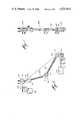
- FIG. 4is a front view of the leg showing motion/module digitizer attachment
- FIG. 5is a rear view of the leg showing the electrogoniometer attachment
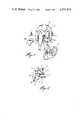
- FIG. 6is a front view of an electronic motion module/digitizer combination in accordance with the invention.
- FIG. 7is a side view of the combination
- FIG. 8illustrates examples of inserts
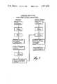
- FIG. 9is a flow chart of software for processing the electrical outputs of the combination to achieve the desired results
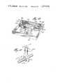
- FIG. 10illustrates a dynanometer in accordance with a further aspect of the invention.
- FIG. 11illustrates in greater detail one of the beams of the invention dynanometer.
- FIGS. 1 to 5there is illustrated a patient 1 having the KLE attached and being examined by a physician 3.
- the KLE systemincludes a thigh restraint means 7, an instrumented seat 9 and a motion module 11.
- the motion moduleis connected at one end 13 to the instrumented seat which, as will be seen below, constitutes a fixed point or body.
- the other end 15is connected to a second point or body.
- the purpose of the instrumentis to determine the movement of the second point or body relative to the first point or body in three dimensional space.
- the instrumented seatmay be mounted on an examining table 17 and consists of a dynanometer 19 which measures applied forces. Instruments for measuring force are described in MEASUREMENT SYSTEMS: APPLICATION AND DESIGN by E. O. Doebelin, McGraw Hill, pps 333-350.
- the instrumented seatmay also have an adjustable seat back arrangement 18 as is well known in the art.
- the thigh restraint 7comprises two or more pairs of off-set straps, which are fastened to each other by fastening means 8, and which displace soft tissue and may also provide a torquing of the tissue about the femur in order to minimize movement of the femur relative to the seat.
- the lower leg attachmentillustrated best in FIGS. 4 and 5, comprises a strap member 21, for example a velcro strap on which is carried the attachment 15a for the end 15 of the motion module.
- the lower leg attachmentfunctions by referencing the motion module to three bony prominences of the lower leg, namely, the tibial crest 23 and the medial and lateral malleoli, 25 and 27 respectively.
- Rollers 29align themselves to the bony contours of the tibial crest, and balls in malleolar cups 31 do the same at the malleoli. These balls and rollers allow the skin to move between the attachment of the bone so that the attachment will move only with the bone which is important in attaining a true bone position measurement.
- the systemalso includes a microprocessor based monitor 33 which receives outputs from the dynanometer and the motion module.
- the KLEis capable of sensing and measuring applied loads and displacements existing during the use of all standard knee evaluation techniques.
- the present KLEis designed to minimize the effects of soft tissue while still permitting the physician to hold, palpate and manipulate the joint as in normal procedures while the KLE provides accurate applied force and tibial-femoral motion readings in displayed and printed form.
- the dynanometer force platemeasures forces and moments in basic directions and permits the physician to know exactly to what levels the knee is being stressed. This is important when measuring laxity since the amount of relative bone motion depends on the stress applied. Knowledge of the forces is of utmost importance to the objective interpretation of joint laxity.
- the motion modulemeasures the true three dimensional position of the tibia relative to the seat, and hence, as the thigh is restrained, to the femur.
- the motion moduleis an electromechanical device which functions on the principle that at least six measurements are required to totally define the position of an object in space as will be further discussed below. It will consist of a means capable of measuring six degree of freedom, three dimensional motion of one point or body relative to another point or body and preferably comprises a unique arrangement of electronic components capable of measuring rotational or translational displacements. A specific module is described below in association with FIGS. 6 to 8. Generally speaking, the two points or bodies between which relative motions are being measured are connected by a single rigid telescopic arm, or a single arm having a joint between its two ends.
- the force measurement on the dynanometeris accomplished through the principles of opposite and equal reaction forces.
- the forces applied to the knee of the patientare reacted to by the femur and thigh which are in turn transmitted to the dynanometer.
- knowledge of the relative position of the relative position of the knee and the dynanometer, provided by the motion modulepermits a theoretical interpretation of the forces and their representation in the co-ordinate system of the knee.
- a patientis seated in the instrumented seat and the thigh of the leg of interest is restrained as shown in FIG. 1.
- the lower leg attachmentis then mounted on the same leg as illustrated in the drawings, and the motion module is connected between the seat and the lower leg attachments. The physician can then twist the lower leg, and he will receive outputs indicating relative displacement as well as force applied.
- FIGS. 6 to 8there is illustrated a particular motion module/digitizer combination which can be used in the KLE environment.
- the combinationcan be used in other systems or it can be used independently.
- itcould be used in association with machine tools and other mechanical systems where it is necessary to be able to measure displacement of a first point or body relative to a second point or body.
- the measurementscan constitute six unique rotational measurements or six unique translational measurements or combinations thereof, i.e., four rotational and two translational, etc.
- the combination in accordance with the inventiontakes five unique measurements of rotational motion and one measurement of translational motion.
- the combinationincludes an elongated member 101 having a first end 103 and a second end 105.
- the elongated membercomprises a first link arm 107 and a second link arm 109.
- the link arms 107 and 109are joined together at 111 to permit relative translational movement as between 103 and 105 and to measure this translational movement.
- the link armsare connected for pivotal motion whereby to permit relative translational motion of 103 and 105, and a rotary transducer means is used to measure this translational motion as will be discussed below.
- one of the armscould include a sleeve for overlying the other arm and for permitting movement of the other arm into and out of the sleeve.
- a translational transducer meanscould be included in the sleeve for measuring the translational motion.
- Examples of rotary transducer means which can be usedare resistive potentiometers, variable inductance transformers, syncro resolvers, inductance potentiometers and variable reluctance transducers.
- Examples of translational transducers which could be usedare dial indicators, resistive potentiometers, variable inductance transformers, capacitance transducers, piezoelectric transducers, ionization transducers and optical transducers.
- a first rotary potentiometer 113Disposed at the end 103 is a first rotary potentiometer 113 which is disposed in line with the arm 103 and rotatable about an axis at right angles to the arm 103.
- a second rotary potentiometer 115is disposed at right angles to the potentiometer 113 and is rotatable about an axis at right angles to the axis of the potentiometer 113.
- Potentiometer 115is mounted on mounting block 117 for mounting the arrangement at one end thereof.
- a third rotary potentiometer 119Disposed at second end 105 is a third rotary potentiometer 119 which is in line with the second link arm 109 and which rotates about an axis at right angles to the second link arm 109.
- a fourth rotary potentiometer 121is disposed at right angles to potentiometer 119 and is rotatable about an axis at right angles to the axis of potentiometer 119.
- a fifth rotary potentiometer 123is also disposed at right angles to potentiometer 119 and is rotatable about an axis at right angles to the axis of potentiometer 119. Potentiometer 123 is also at right angles to potentiometer 121 and its axis of rotation is also at right angles to the axis of potentiometer 121.
- Potentiometer 123is connected to mounting block 25 for mounting the arrangement at a second point.
- arms 107 and 109are connected at 111 by a sixth rotary potentiometer 127 which is in line with both arms 107 and 109 and whose axis of rotation is at right angles to both arms 107 and 109.
- the arrangement as thus far describedcan measure the motion in three dimensional space of end 105 relative to end 103 or vice-versa and is referred to as motion module.
- motion modulethere is provided the potential for digitizing the positions of third, fourth, fifth . . . nth points or bodies (henceforth, the use of the term points will be used and understood to refer to points or bodies) in three dimensional space, or combinations thereof, and of then measuring the motion or position of one of the points 103 and 105 relative to the position of the other point or relative to the third, fourth, fifth . . . nth points, or positions of the second body, or combinations thereof.
- This potentialis achieved by making one of the link arms disconnectable from its respective mounting block and reconnectable again thereto.
- link arm 109is disconnectable from mounting block 125.
- the protrusion 129which extends from potentiometer 119 is insertable into a receptacle 131.
- the protrusionis also removable from the receptacle, and other inserts, such as those illustrated in FIGS. 8A, 8B, etc. can be inserted into the receptacle for digitizing the positions of other points in space.
- potentiometers 113, 115 and 127define a spherical co-ordinate system about 0.
- potentiometers 113 and 115provide the conventional angles ⁇ and ⁇ respectively, while the potentiometer 127, combined with 107 and 109, provide the length of the vector R. (Knowing the length of 107 and 109, and knowing the angle therebetween, it is quite easy to determine the length of the vector R).
- Point Bis defined as the intersection of the axes of potentiometers 119, 121 and 123 and is considered the origin of the "moving body" co-ordinate system.
- 0is considered the origin of a "fixed" body or co-ordinate system.
- mounting block 125would be mounted on a moving body.
- Mounting block 117would be mounted on the fixed body or co-ordinate system, and the measurement of the movement of 105 relative to 103 would define the motion of the moving body relative to the fixed body or co-ordinate system.
- the final description of the moving body motionis contained in the three finite rotations provided by the potentiometers 119, 121 and 123.
- the protrusion 119is removed from the receptacle 131, and one of the digitizer tips illustrated in FIG. 8 is inserted into the receptacle in place of the protrusion 119.
- the tipis then pointed at points of interest, namely, a third, fourth, fifth . . . nth points above-mentioned, and a reading is taken of the three dimensional position in space of these points.
- conductive leads from the potentiometerswill be brought to a connecting board, which could be disposed on the mounting blocks 117, so that the electrical signals developed at the potentiometers can be brought to a processing means such as the processing means illustrated schematically at 133 in FIG. 1. It will, of course, be necessary to provide DC power to the potentiometer to measure the changing resistance thereof, as well known in the art, and this DC power could also be provided from the processing means 133.
- the potentiometerswill provide the data for determining the extent and direction of the motion of point 105. In order to determine the direction and extent, the data must be processed. Preferably, the data is processed by computer means. A flow chart for controlling such a computer is illustrated in FIG. 8.
- DIGMATdigital transformation matrix
- DIGITdigitalization
- NEWTIPsupport routine for user defined tip
- the protrusion 129is removed from the receptacle 131, and one of a variety of tips is inserted in the receptacle.
- the mounting blocks 117must be firmly mounted at a position which both permits easy access to most points of interest and is also appropriate for any subsequent motion measurement using both upper and lower components of the motion module. A position of interest is then pointed at with the tip.
- the physical characteristicsare inputted into the computer memory, and a code is then presented to the computer to let it know which of the tips is being used.
- the programUpon pointing at the position with the tip, the program must be activated either through a remote switch or a keyboard entry.
- the control programwill then scan the signals in the potentiometer, and then, in sequence, call the subroutine DIGMAT, which uses as input the voltage values of potentiometers 113, 115 and 127, as well as the voltage of the power supply.
- DIGMAToutputs to transformation matrices which are used in the subroutine digit which is the next subroutine to be called.
- DIGITactually computes the position of DTIP in the global coordinate system using as input the output of DIGMAT and DTIP coordinates in potentiometer 127 coordinate system.
- the TIPis then removed from the receptacle 131 and the protrusion 129 is again inserted in the receptacle.
- the subroutine LOCTRNwhich computes the coordinates of the digitized points in the local coordinate system (that is, with the point B as an origin) is then called. These points are then outputted to the GLOTRN subroutine which will be discussed below.
- the mounting block 125would have been attached to a point of interest. Displacements of this point are performed, and the potentiometer signals are once again scanned. This data is communicated to the computer and the subroutine DISMAT is called. DISMAT computes the contents of the transformation matrix describing the body in three dimensional space. The subroutine GLOTRN is then called and outputs new positions of those points previously digitized on the body or analytically generated points, in the global system. This procedure continues as the point of interest moves through different positions.
- This subroutinecomputes matrix DT12 as well as matrix DT3 which locates the position of potentiometer-113 and potentiometer-127 coordinate systems, respectively.
- DT12 (3,3) and DT3 (3,3)are the abovementioned matrices. (Note 1)
- This subroutinecomputes the coordinates of the digitizer tip with respect to the global coordinate system.
- DT12 (3,3), and DT3 (3,3)locate the position of potentiometer-113 and potentiometer-127 coordinate systems, respectively. (Refer to subroutine DIGMAT). (Note 3)
- DTIP (3)are the coordinates of the tip in use with respect to the potentiometer-127 coordinate system. (Note 1, 2 and 3)
- DPNTRF (3)are the coordinates of the tip with respect to the global coordinate system. (Note 2 and 3)
- the main purpose of this subroutineis to define the coordinates of any user-designed tip with respect to potentiometer-127 coordinate system without independently measuring the tip dimensions.
- first mount tip number 1see 8b
- touch a pointNote 1
- the coordinates of the pointare computed by tip number 1 and are used to compute the constants for the new tip. (Refer to the Control Program Flow Chart).
- DT12 (3,3), and DT3 (3,3)locate the position of potentiometer-113 and potentiometer-127 coordinate systems, respectively.
- DPNTRF (3)coordinates of the digitized point by tip number 1 with respect to global coordinate system. (Note 1 and 2)
- DTIP(3)coordinates of the tip with respect to potentiometer-127 coordinate system, or better known as the new tip constants. (Note 1 and 2)
- 2--In the coordinate system arrays 1, 2 and 3are X, Y and Z coordinates, respectively.
- DISMATcomputes the position of the local coordinate system with respect to the global coordinate system.
- the local coordinate systemis in line with indicated edges of upper mounting block.
- DMAT2 (4,3)consists of:
- DMAT2 (4,1), DMAT2 (4,2) and DMAT2 (4,3)are the coordinates of point B in global coordinate system.
- DMAT2 (3,3)defines the position of the local coordinates system with respect to the global coordinate system. (Note 1)
- DMAT 2 (4,3)is input only to subroutines LOCTRN and GLOTRN, and has no significance to the user.
- LOCTRNcomputes the coordinates of the digitized points in local coordinate system.
- Nis number of points; integer
- 2--In the coordinates arrays 1, 2 and 3are X, Y and Z coordinates, respectively.
- GLOTRNcomputes the new coordinates of the points in the global coordinate system.
- NN number of points; integer.
- DPNTLC (3,N)coordinates of the points in local coordinate system. (Note 1 and 2)
- 2--In the coordinate arrays 1, 2 and 3are X, Y and Z coordinates, respectively.
- the dynanometercomprises a supporting frame 201 which, in the illustrated embodiment, comprises a four walled structure. Disposed centrally of one wall is a first spherical or rectangular beam 203. Second and third rectangular or spherical beams 205 and 207 are disposed in the corners opposite the wall of the 203 beam.
- each beamcomprises a vertical support portion 209 and horizontal deflection member 211.
- the vertical and horizontal membersare joined by spherical/linear bearings 213.
- the bearingsare the key to the proper operation of this triple beam system since they release all moments at the beams permitting the moments to be measured at various beams through their respective bending deflections, rather than being lost as axial beam compression or pure moments.
- each deflection member 211is the perpendicular bisector of a respective side of an equilateral triangle. This particular arrangement is convenient for subsequent analyses.
- a platform 215.Supported at the top surfaces of the vertical members is a platform 215.
- the platformcan be of any convenient shape, so long as it is supported by the top surfaces of the vertical members.
- the platform 215forms an equilateral triangle, and a beam is disposed at each corner of the triangle.
- the horizontal member of the beamis perpendicular to the side of the triangle opposite its corner.
- the beamsare at the corners of an equilateral triangle, any arrangement of three beams where there are no two redundant directions of deflections are permissible for two reasons:
- Devicesillustrated schematically at 217 and 219 with respect to beam 203, 221, 223 with respect to beam 207 and 225, 227 with respect to beam 205 are used to measure the deflection of the beams.
- the devicescan comprise conventional displacement transducer devices and they would be mounted onto the rigid support frame and in such a manner that deflections in only the two planes of interest are measured for each beam.
- the resulting force measurementswould be the minimum required to fully define all the external forces and moments acting on the platform.
- the necessary formulations for equilibrium of rigid bodyare the subject of numerous engineering text.
- the deflections for each beamwill be resolved in two directions through each beam.
- One directionis parallel to the axis of the vertical member and consists of the forces labelled F2, F4, F6, and the other direction is perpendicular to the first direction as illustrated by the arrows labelled F1, F3 and F5.
- the devices 217, 221 and 227measure the forces in the directions F2, F4 and F6, while the devices 217, 223 and 225 measure the forces in the direction F1, F3 and F5.
- the beams 203, 205 and 207When a force is applied to the platform 215, depending on the magnitude of the force and the direction of the application thereof, the beams 203, 205 and 207 will be deflected by different amounts.
- the magnitudes of deflectionare resolved in the two directions as above-described, and the magnitudes in the respective directions are measured by the devices 217 to 227. Using this technology and well-known mathematical vector transformations, the force applied at the platform can be calculated.
Landscapes
- Health & Medical Sciences (AREA)
- Life Sciences & Earth Sciences (AREA)
- Physics & Mathematics (AREA)
- Biomedical Technology (AREA)
- Medical Informatics (AREA)
- General Physics & Mathematics (AREA)
- Oral & Maxillofacial Surgery (AREA)
- Biophysics (AREA)
- Pathology (AREA)
- Engineering & Computer Science (AREA)
- Dentistry (AREA)
- Heart & Thoracic Surgery (AREA)
- Veterinary Medicine (AREA)
- Molecular Biology (AREA)
- Surgery (AREA)
- Animal Behavior & Ethology (AREA)
- General Health & Medical Sciences (AREA)
- Public Health (AREA)
- Rheumatology (AREA)
- Physiology (AREA)
- Orthopedic Medicine & Surgery (AREA)
- Length Measuring Devices With Unspecified Measuring Means (AREA)
Abstract
Description
Claims (6)
Priority Applications (1)
| Application Number | Priority Date | Filing Date | Title |
|---|---|---|---|
| US06/735,080US4571834A (en) | 1984-02-17 | 1985-05-16 | Knee laxity evaluator and motion module/digitizer arrangement |
Applications Claiming Priority (2)
| Application Number | Priority Date | Filing Date | Title |
|---|---|---|---|
| US06/581,432US4549555A (en) | 1984-02-17 | 1984-02-17 | Knee laxity evaluator and motion module/digitizer arrangement |
| US06/735,080US4571834A (en) | 1984-02-17 | 1985-05-16 | Knee laxity evaluator and motion module/digitizer arrangement |
Related Parent Applications (1)
| Application Number | Title | Priority Date | Filing Date |
|---|---|---|---|
| US06/581,432DivisionUS4549555A (en) | 1984-01-27 | 1984-02-17 | Knee laxity evaluator and motion module/digitizer arrangement |
Publications (1)
| Publication Number | Publication Date |
|---|---|
| US4571834Atrue US4571834A (en) | 1986-02-25 |
Family
ID=27078328
Family Applications (1)
| Application Number | Title | Priority Date | Filing Date |
|---|---|---|---|
| US06/735,080Expired - Fee RelatedUS4571834A (en) | 1984-02-17 | 1985-05-16 | Knee laxity evaluator and motion module/digitizer arrangement |
Country Status (1)
| Country | Link |
|---|---|
| US (1) | US4571834A (en) |
Cited By (167)
| Publication number | Priority date | Publication date | Assignee | Title |
|---|---|---|---|---|
| US4649934A (en)* | 1985-06-07 | 1987-03-17 | Faro Medical Technologies, Inc. | Joint laxity measurement |
| US4667685A (en)* | 1985-09-23 | 1987-05-26 | Fine Edward J | Goniometric feedback device and method for monitoring angles of body joints |
| US4760851A (en)* | 1986-03-31 | 1988-08-02 | Faro Medical Technologies Inc. | 3-dimensional digitizer for skeletal analysis |
| US4800897A (en)* | 1985-06-24 | 1989-01-31 | Se-Produkter | Device for detection of relative movements and/or positions of a part of the body or the like |
| AU585710B2 (en)* | 1986-03-27 | 1989-06-22 | Mervin John Cross | Measurement of laxity of anterior cruciate ligament |
| US4909262A (en)* | 1989-01-31 | 1990-03-20 | Orthopedic Systems, Inc. | Apparatus for obtaining a body limb torque signal |
| US4915374A (en)* | 1989-02-02 | 1990-04-10 | Medmetric Corporation | Recumbent exercise cycle with articulated pedals |
| US4922925A (en)* | 1988-02-29 | 1990-05-08 | Washington University | Computer based upper extremity evaluation system |
| US5050608A (en)* | 1988-07-12 | 1991-09-24 | Medirand, Inc. | System for indicating a position to be operated in a patient's body |
| US5080109A (en)* | 1991-02-15 | 1992-01-14 | Arme Jr Joseph F | Method and apparatus for analysis of postural abnormalities |
| US5082001A (en)* | 1989-02-27 | 1992-01-21 | Vannier Michael W | Enhanced computer based upper extremity evaluation system |
| US5082003A (en)* | 1990-01-05 | 1992-01-21 | Orthopedic Systems, Inc. | Apparatus for determining interskeletal distances |
| US5251127A (en)* | 1988-02-01 | 1993-10-05 | Faro Medical Technologies Inc. | Computer-aided surgery apparatus |
| US5305203A (en)* | 1988-02-01 | 1994-04-19 | Faro Medical Technologies Inc. | Computer-aided surgery apparatus |
| US5313968A (en)* | 1990-04-23 | 1994-05-24 | Washington University | Joint range of motion analyzer using euler angle |
| US5337758A (en)* | 1991-01-11 | 1994-08-16 | Orthopedic Systems, Inc. | Spine motion analyzer and method |
| US5348025A (en)* | 1993-02-22 | 1994-09-20 | Yale University | Apparatus and method for measuring mobility of the scaphoid |
| US5373858A (en)* | 1993-07-09 | 1994-12-20 | Technostix, Inc. | Apparatus and method for determining angle of inclination and range of motion of various human joints therefrom |
| US5402800A (en)* | 1993-08-02 | 1995-04-04 | Hollis; J. Marcus | Ankle laxity measurement system |
| US5402582A (en)* | 1993-02-23 | 1995-04-04 | Faro Technologies Inc. | Three dimensional coordinate measuring apparatus |
| US5442858A (en)* | 1992-11-23 | 1995-08-22 | Resonex Holding Company | Automated angle encoder system for MRI apparatus |
| US5474088A (en)* | 1993-12-09 | 1995-12-12 | The Research Foundation Of State University Of New York | Device for measuring motion characteristics of a human joint |
| US5483961A (en)* | 1993-03-19 | 1996-01-16 | Kelly; Patrick J. | Magnetic field digitizer for stereotactic surgery |
| US5520694A (en)* | 1993-06-21 | 1996-05-28 | Dance; Mark N. | Apparatus and method for aligning knee prostheses |
| US5576727A (en)* | 1993-07-16 | 1996-11-19 | Immersion Human Interface Corporation | Electromechanical human-computer interface with force feedback |
| USD377932S (en)* | 1995-10-31 | 1997-02-11 | Immersion Human Interface Corporation | Mechanical digitizing arm used to input three dimensional data into a computer |
| US5601566A (en)* | 1994-02-22 | 1997-02-11 | Osteonics Corp. | Method and apparatus for the alignment of a femoral knee prosthesis |
| US5611353A (en)* | 1993-06-21 | 1997-03-18 | Osteonics Corp. | Method and apparatus for locating functional structures of the lower leg during knee surgery |
| US5611147A (en)* | 1993-02-23 | 1997-03-18 | Faro Technologies, Inc. | Three dimensional coordinate measuring apparatus |
| US5623582A (en)* | 1994-07-14 | 1997-04-22 | Immersion Human Interface Corporation | Computer interface or control input device for laparoscopic surgical instrument and other elongated mechanical objects |
| US5691898A (en)* | 1995-09-27 | 1997-11-25 | Immersion Human Interface Corp. | Safe and low cost computer peripherals with force feedback for consumer applications |
| US5721566A (en)* | 1995-01-18 | 1998-02-24 | Immersion Human Interface Corp. | Method and apparatus for providing damping force feedback |
| US5724264A (en)* | 1993-07-16 | 1998-03-03 | Immersion Human Interface Corp. | Method and apparatus for tracking the position and orientation of a stylus and for digitizing a 3-D object |
| US5731804A (en)* | 1995-01-18 | 1998-03-24 | Immersion Human Interface Corp. | Method and apparatus for providing high bandwidth, low noise mechanical I/O for computer systems |
| US5734373A (en)* | 1993-07-16 | 1998-03-31 | Immersion Human Interface Corporation | Method and apparatus for controlling force feedback interface systems utilizing a host computer |
| US5739811A (en)* | 1993-07-16 | 1998-04-14 | Immersion Human Interface Corporation | Method and apparatus for controlling human-computer interface systems providing force feedback |
| US5767839A (en)* | 1995-01-18 | 1998-06-16 | Immersion Human Interface Corporation | Method and apparatus for providing passive force feedback to human-computer interface systems |
| US5787886A (en)* | 1993-03-19 | 1998-08-04 | Compass International Incorporated | Magnetic field digitizer for stereotatic surgery |
| US5805140A (en)* | 1993-07-16 | 1998-09-08 | Immersion Corporation | High bandwidth force feedback interface using voice coils and flexures |
| US5821920A (en)* | 1994-07-14 | 1998-10-13 | Immersion Human Interface Corporation | Control input device for interfacing an elongated flexible object with a computer system |
| US5822873A (en)* | 1996-11-01 | 1998-10-20 | Meilman; Henry | Device for determining cants for skiers and method of use |
| US5828197A (en)* | 1996-10-25 | 1998-10-27 | Immersion Human Interface Corporation | Mechanical interface having multiple grounded actuators |
| US5848967A (en)* | 1991-01-28 | 1998-12-15 | Cosman; Eric R. | Optically coupled frameless stereotactic system and method |
| US5851183A (en)* | 1990-10-19 | 1998-12-22 | St. Louis University | System for indicating the position of a surgical probe within a head on an image of the head |
| US5871445A (en)* | 1993-04-26 | 1999-02-16 | St. Louis University | System for indicating the position of a surgical probe within a head on an image of the head |
| US5898599A (en)* | 1993-10-01 | 1999-04-27 | Massachusetts Institute Of Technology | Force reflecting haptic interface |
| US5911695A (en)* | 1997-11-03 | 1999-06-15 | Medmetric Corporation | Shoulder tester |
| US6006126A (en)* | 1991-01-28 | 1999-12-21 | Cosman; Eric R. | System and method for stereotactic registration of image scan data |
| US6028593A (en)* | 1995-12-01 | 2000-02-22 | Immersion Corporation | Method and apparatus for providing simulated physical interactions within computer generated environments |
| US6146390A (en)* | 1992-04-21 | 2000-11-14 | Sofamor Danek Holdings, Inc. | Apparatus and method for photogrammetric surgical localization |
| US6167145A (en)* | 1996-03-29 | 2000-12-26 | Surgical Navigation Technologies, Inc. | Bone navigation system |
| US6219032B1 (en) | 1995-12-01 | 2001-04-17 | Immersion Corporation | Method for providing force feedback to a user of an interface device based on interactions of a controlled cursor with graphical elements in a graphical user interface |
| US6236875B1 (en) | 1994-10-07 | 2001-05-22 | Surgical Navigation Technologies | Surgical navigation systems including reference and localization frames |
| US6235038B1 (en) | 1999-10-28 | 2001-05-22 | Medtronic Surgical Navigation Technologies | System for translation of electromagnetic and optical localization systems |
| US6240646B1 (en)* | 1998-06-26 | 2001-06-05 | Pullmax Ursviken Ab | Device for measuring angles |
| US6296613B1 (en) | 1997-08-22 | 2001-10-02 | Synthes (U.S.A.) | 3D ultrasound recording device |
| US6347240B1 (en) | 1990-10-19 | 2002-02-12 | St. Louis University | System and method for use in displaying images of a body part |
| US20020030664A1 (en)* | 1995-11-17 | 2002-03-14 | Immersion Corporation | Force feedback interface device with force functionality button |
| US6366831B1 (en) | 1993-02-23 | 2002-04-02 | Faro Technologies Inc. | Coordinate measurement machine with articulated arm and software interface |
| US6381485B1 (en) | 1999-10-28 | 2002-04-30 | Surgical Navigation Technologies, Inc. | Registration of human anatomy integrated for electromagnetic localization |
| US20020050978A1 (en)* | 1995-12-13 | 2002-05-02 | Immersion Corporation | Force feedback applications based on cursor engagement with graphical targets |
| US6405072B1 (en) | 1991-01-28 | 2002-06-11 | Sherwood Services Ag | Apparatus and method for determining a location of an anatomical target with reference to a medical apparatus |
| US20020109705A1 (en)* | 1999-05-03 | 2002-08-15 | Robert Hofstetter | System and method for preparing an image corrected for the presence of a gravity induced distortion |
| US20020147415A1 (en)* | 2000-12-30 | 2002-10-10 | Sandra Martelli | Method for simultaneous anatomical and functional mapping of a joint |
| US20020183610A1 (en)* | 1994-10-07 | 2002-12-05 | Saint Louis University And Surgical Navigation Technologies, Inc. | Bone navigation system |
| US20030030621A1 (en)* | 1993-07-16 | 2003-02-13 | Rosenberg Louis B. | Force feeback device including flexure member between actuator and user object |
| US20030073901A1 (en)* | 1999-03-23 | 2003-04-17 | Simon David A. | Navigational guidance via computer-assisted fluoroscopic imaging |
| US6551258B1 (en) | 2000-08-02 | 2003-04-22 | The State Of Oregon Acting By And Through The State Board Of Higher Education On Behalf Of Oregon State Univerisity | Methods and apparatus for joint laxity measurements |
| US20030114752A1 (en)* | 1999-04-20 | 2003-06-19 | Jaimie Henderson | Instrument guidance method and system for image guided surgery |
| US20030117135A1 (en)* | 1999-10-28 | 2003-06-26 | Martinelli Michael A. | Method and system for navigating a catheter probe in the presence of field-influencing objects |
| US6585651B2 (en) | 1999-04-20 | 2003-07-01 | Synthes Ag Chur | Method and device for percutaneous determination of points associated with the surface of an organ |
| US20030167647A1 (en)* | 2002-02-14 | 2003-09-11 | Simon Raab | Portable coordinate measurement machine |
| US6675040B1 (en) | 1991-01-28 | 2004-01-06 | Sherwood Services Ag | Optical object tracking system |
| US6694168B2 (en) | 1998-06-22 | 2004-02-17 | Synthes (U.S.A.) | Fiducial matching using fiducial implants |
| US6697748B1 (en) | 1995-08-07 | 2004-02-24 | Immersion Corporation | Digitizing system and rotary table for determining 3-D geometry of an object |
| US6725080B2 (en) | 2000-03-01 | 2004-04-20 | Surgical Navigation Technologies, Inc. | Multiple cannula image guided tool for image guided procedures |
| US6725082B2 (en) | 1999-03-17 | 2004-04-20 | Synthes U.S.A. | System and method for ligament graft placement |
| US20040097806A1 (en)* | 2002-11-19 | 2004-05-20 | Mark Hunter | Navigation system for cardiac therapies |
| US20040097805A1 (en)* | 2002-11-19 | 2004-05-20 | Laurent Verard | Navigation system for cardiac therapies |
| US20040103547A1 (en)* | 2002-02-14 | 2004-06-03 | Simon Raab | Portable coordinate measurement machine |
| US20040111908A1 (en)* | 2002-02-14 | 2004-06-17 | Simon Raab | Method for improving measurement accuracy of a protable coordinate measurement machine |
| US20040152970A1 (en)* | 2003-01-30 | 2004-08-05 | Mark Hunter | Six degree of freedom alignment display for medical procedures |
| US20040160415A1 (en)* | 1995-12-01 | 2004-08-19 | Rosenberg Louis B. | Designing force sensations for force feedback computer applications |
| US20040171924A1 (en)* | 2003-01-30 | 2004-09-02 | Mire David A. | Method and apparatus for preplanning a surgical procedure |
| US20040187601A1 (en)* | 2003-03-24 | 2004-09-30 | Atsuhiro Konosu | Leg shocking device for pedestrian protection test |
| US20040215071A1 (en)* | 2003-04-25 | 2004-10-28 | Frank Kevin J. | Method and apparatus for performing 2D to 3D registration |
| US20040227727A1 (en)* | 1995-11-17 | 2004-11-18 | Schena Bruce M. | Force feedback device including actuator with moving magnet |
| US20040260208A1 (en)* | 2003-06-20 | 2004-12-23 | Robert Laprade | Knee laxity measurement |
| US20050016008A1 (en)* | 2002-02-14 | 2005-01-27 | Simon Raab | Method for providing sensory feedback to the operator of a portable measurement machine |
| US6850222B1 (en) | 1995-01-18 | 2005-02-01 | Immersion Corporation | Passive force feedback for computer interface devices |
| US6859819B1 (en) | 1995-12-13 | 2005-02-22 | Immersion Corporation | Force feedback enabled over a computer network |
| US20050059885A1 (en)* | 1997-12-12 | 2005-03-17 | Tony Melkent | Image guided spinal surgery guide, system and method for use thereof |
| US20050085714A1 (en)* | 2003-10-16 | 2005-04-21 | Foley Kevin T. | Method and apparatus for surgical navigation of a multiple piece construct for implantation |
| US20050085720A1 (en)* | 2003-10-17 | 2005-04-21 | Jascob Bradley A. | Method and apparatus for surgical navigation |
| US20050093821A1 (en)* | 2003-10-30 | 2005-05-05 | Sensable Technologies, Inc. | Force reflecting haptic interface |
| US20050143651A1 (en)* | 2002-08-19 | 2005-06-30 | Laurent Verard | Method and apparatus for virtual endoscopy |
| US20050165292A1 (en)* | 2002-04-04 | 2005-07-28 | Simon David A. | Method and apparatus for virtual digital subtraction angiography |
| US6948502B2 (en) | 2002-05-09 | 2005-09-27 | Mayo Foundation For Medical Education And Research | Method and apparatus for positioning a forearm for imaging and analysis |
| US6959573B2 (en) | 2000-08-11 | 2005-11-01 | Amada Company, Limited | Bending method and device therefore |
| US20050245817A1 (en)* | 2004-05-03 | 2005-11-03 | Clayton John B | Method and apparatus for implantation between two vertebral bodies |
| US20050273004A1 (en)* | 2002-02-28 | 2005-12-08 | Simon David A | Method and apparatus for perspective inversion |
| US20060016086A1 (en)* | 2002-02-14 | 2006-01-26 | Simon Raab | Portable coordinate measurement machine |
| US20060025677A1 (en)* | 2003-10-17 | 2006-02-02 | Verard Laurent G | Method and apparatus for surgical navigation |
| US20060036151A1 (en)* | 1994-09-15 | 2006-02-16 | Ge Medical Systems Global Technology Company | System for monitoring a position of a medical instrument |
| US20060084867A1 (en)* | 2003-10-17 | 2006-04-20 | Tremblay Brian M | Method and apparatus for surgical navigation |
| US7039866B1 (en) | 1995-12-01 | 2006-05-02 | Immersion Corporation | Method and apparatus for providing dynamic force sensations for force feedback computer applications |
| US20060094958A1 (en)* | 2004-10-28 | 2006-05-04 | Marquart Joel G | Method and apparatus for calibrating non-linear instruments |
| US20060099560A1 (en)* | 2001-07-16 | 2006-05-11 | Immersion Corporation | Interface apparatus with cable-driven force feedback and four grounded actuators |
| US20060129349A1 (en)* | 2002-02-14 | 2006-06-15 | Simon Raab | Portable coordinate measurement machine with integrated line laser scanner |
| US7085400B1 (en) | 2000-06-14 | 2006-08-01 | Surgical Navigation Technologies, Inc. | System and method for image based sensor calibration |
| US20060190823A1 (en)* | 2001-05-04 | 2006-08-24 | Immersion Corporation | Haptic interface for palpation simulation |
| US7113166B1 (en) | 1995-06-09 | 2006-09-26 | Immersion Corporation | Force feedback devices using fluid braking |
| US20060278247A1 (en)* | 1999-10-28 | 2006-12-14 | Mark W. Hunter Et Al. | Surgical communication and power system |
| US7209117B2 (en) | 1995-12-01 | 2007-04-24 | Immersion Corporation | Method and apparatus for streaming force values to a force feedback device |
| US20070166188A1 (en)* | 2006-01-18 | 2007-07-19 | Eric Ryterski | Method and apparatus for providing a container to a sterile environment |
| US20070167722A1 (en)* | 1992-08-14 | 2007-07-19 | British Telecommunications Public Limited Company | Surgical navigation |
| US20070249911A1 (en)* | 2006-04-21 | 2007-10-25 | Simon David A | Method and apparatus for optimizing a therapy |
| US20070294045A1 (en)* | 2002-02-14 | 2007-12-20 | Faro Technologies, Inc. | Portable coordinate measurement machine with integrated line laser scanner |
| US7313430B2 (en) | 2003-08-28 | 2007-12-25 | Medtronic Navigation, Inc. | Method and apparatus for performing stereotactic surgery |
| US20080081982A1 (en)* | 2006-09-29 | 2008-04-03 | Medtronic, Inc. | Method And Apparatus For Optimizing A Computer Assisted Surgical Procedure |
| US20090088600A1 (en)* | 2007-09-27 | 2009-04-02 | Superdimension, Ltd. | Bronchoscope Adapter and Method |
| US20090240198A1 (en)* | 2004-02-09 | 2009-09-24 | Superdimension, Ltd. | Directional Anchoring Mechanism, Method And Applications Thereof |
| US20090287443A1 (en)* | 2001-06-04 | 2009-11-19 | Surgical Navigation Technologies, Inc. | Method for Calibrating a Navigation System |
| US20090284255A1 (en)* | 2008-04-03 | 2009-11-19 | Superdimension, Ltd | Magnetic Interference Detection System And Method |
| US20100016757A1 (en)* | 2008-07-10 | 2010-01-21 | Superdimension, Ltd. | Integrated Multi-Functional Endoscopic Tool |
| US20100030064A1 (en)* | 2008-06-03 | 2010-02-04 | Super Dimension, Ltd. | Feature-Based Registration Method |
| US20100152571A1 (en)* | 2008-12-16 | 2010-06-17 | Medtronic Navigation, Inc | Combination of electromagnetic and electropotential localization |
| US20100210939A1 (en)* | 1999-10-28 | 2010-08-19 | Medtronic Navigation, Inc. | Method and Apparatus for Surgical Navigation |
| US7835784B2 (en) | 2005-09-21 | 2010-11-16 | Medtronic Navigation, Inc. | Method and apparatus for positioning a reference frame |
| US7853305B2 (en) | 2000-04-07 | 2010-12-14 | Medtronic Navigation, Inc. | Trajectory storage apparatus and method for surgical navigation systems |
| US7881896B2 (en) | 2002-02-14 | 2011-02-01 | Faro Technologies, Inc. | Portable coordinate measurement machine with integrated line laser scanner |
| USRE42082E1 (en) | 2002-02-14 | 2011-02-01 | Faro Technologies, Inc. | Method and apparatus for improving measurement accuracy of a portable coordinate measurement machine |
| USRE42194E1 (en) | 1997-09-24 | 2011-03-01 | Medtronic Navigation, Inc. | Percutaneous registration apparatus and method for use in computer-assisted surgical navigation |
| US20110054293A1 (en)* | 2009-08-31 | 2011-03-03 | Medtronic, Inc. | Combination Localization System |
| US20110054304A1 (en)* | 2009-08-31 | 2011-03-03 | Medtronic, Inc. | Combination Localization System |
| US7998062B2 (en) | 2004-03-29 | 2011-08-16 | Superdimension, Ltd. | Endoscope structures and techniques for navigating to a target in branched structure |
| US20110207997A1 (en)* | 2009-04-08 | 2011-08-25 | Superdimension, Ltd. | Locatable Catheter |
| US8057407B2 (en) | 1999-10-28 | 2011-11-15 | Medtronic Navigation, Inc. | Surgical sensor |
| US8165658B2 (en) | 2008-09-26 | 2012-04-24 | Medtronic, Inc. | Method and apparatus for positioning a guide relative to a base |
| USRE43328E1 (en) | 1997-11-20 | 2012-04-24 | Medtronic Navigation, Inc | Image guided awl/tap/screwdriver |
| USRE43952E1 (en) | 1989-10-05 | 2013-01-29 | Medtronic Navigation, Inc. | Interactive system for local intervention inside a non-homogeneous structure |
| US8452068B2 (en) | 2008-06-06 | 2013-05-28 | Covidien Lp | Hybrid registration method |
| US8508469B1 (en) | 1995-12-01 | 2013-08-13 | Immersion Corporation | Networked applications including haptic feedback |
| TWI422359B (en)* | 2011-03-31 | 2014-01-11 | Univ Nat Taiwan Ocean | Knee ligament laxity measuring device |
| US8663088B2 (en) | 2003-09-15 | 2014-03-04 | Covidien Lp | System of accessories for use with bronchoscopes |
| US8768437B2 (en) | 1998-08-20 | 2014-07-01 | Sofamor Danek Holdings, Inc. | Fluoroscopic image guided surgery system with intraoperative registration |
| US20140316545A1 (en)* | 2008-03-25 | 2014-10-23 | Orthosoft, Inc. | Method and system for planning/guiding alterations to a bone |
| US9055881B2 (en) | 2004-04-26 | 2015-06-16 | Super Dimension Ltd. | System and method for image-based alignment of an endoscope |
| US20170347942A1 (en)* | 2016-06-03 | 2017-12-07 | Ermi, Inc. | Robotic Joint Testing Apparatus and Coordinate Systems for Joint Evaluation and Testing |
| US10418705B2 (en) | 2016-10-28 | 2019-09-17 | Covidien Lp | Electromagnetic navigation antenna assembly and electromagnetic navigation system including the same |
| US10426555B2 (en) | 2015-06-03 | 2019-10-01 | Covidien Lp | Medical instrument with sensor for use in a system and method for electromagnetic navigation |
| US10446931B2 (en) | 2016-10-28 | 2019-10-15 | Covidien Lp | Electromagnetic navigation antenna assembly and electromagnetic navigation system including the same |
| US10478254B2 (en) | 2016-05-16 | 2019-11-19 | Covidien Lp | System and method to access lung tissue |
| US10517505B2 (en) | 2016-10-28 | 2019-12-31 | Covidien Lp | Systems, methods, and computer-readable media for optimizing an electromagnetic navigation system |
| US10582834B2 (en) | 2010-06-15 | 2020-03-10 | Covidien Lp | Locatable expandable working channel and method |
| US10615500B2 (en) | 2016-10-28 | 2020-04-07 | Covidien Lp | System and method for designing electromagnetic navigation antenna assemblies |
| US10638952B2 (en) | 2016-10-28 | 2020-05-05 | Covidien Lp | Methods, systems, and computer-readable media for calibrating an electromagnetic navigation system |
| US10722311B2 (en) | 2016-10-28 | 2020-07-28 | Covidien Lp | System and method for identifying a location and/or an orientation of an electromagnetic sensor based on a map |
| US10751126B2 (en) | 2016-10-28 | 2020-08-25 | Covidien Lp | System and method for generating a map for electromagnetic navigation |
| US10792106B2 (en) | 2016-10-28 | 2020-10-06 | Covidien Lp | System for calibrating an electromagnetic navigation system |
| US10952593B2 (en) | 2014-06-10 | 2021-03-23 | Covidien Lp | Bronchoscope adapter |
| US11006914B2 (en) | 2015-10-28 | 2021-05-18 | Medtronic Navigation, Inc. | Apparatus and method for maintaining image quality while minimizing x-ray dosage of a patient |
| US11219489B2 (en) | 2017-10-31 | 2022-01-11 | Covidien Lp | Devices and systems for providing sensors in parallel with medical tools |
| US11224443B2 (en) | 2008-03-25 | 2022-01-18 | Orthosoft Ulc | Method and system for planning/guiding alterations to a bone |
| US11331150B2 (en) | 1999-10-28 | 2022-05-17 | Medtronic Navigation, Inc. | Method and apparatus for surgical navigation |
| US20240019278A1 (en)* | 2021-01-28 | 2024-01-18 | Fanuc Corporation | Displacement detecting sensor, control device, and control system |
| US12089902B2 (en) | 2019-07-30 | 2024-09-17 | Coviden Lp | Cone beam and 3D fluoroscope lung navigation |
Citations (4)
| Publication number | Priority date | Publication date | Assignee | Title |
|---|---|---|---|---|
| DE2754500A1 (en)* | 1976-12-22 | 1978-06-29 | Teledyne Ind | DEVICE FOR MEASURING THE POSITION OF POINTS ON LINEAR SECTIONS OF A PRE-FABRICATED PIPE |
| US4306571A (en)* | 1980-03-31 | 1981-12-22 | Orthopaedic Research Institute, Inc. | Dynamic joint motion analysis technique |
| US4436099A (en)* | 1981-08-14 | 1984-03-13 | The University Of Toledo | Instrument for measuring the range of motion associated with a human body joint |
| US4486955A (en)* | 1982-04-28 | 1984-12-11 | Marconi Avionics Limited | Angular position sensors |
- 1985
- 1985-05-16USUS06/735,080patent/US4571834A/ennot_activeExpired - Fee Related
Patent Citations (4)
| Publication number | Priority date | Publication date | Assignee | Title |
|---|---|---|---|---|
| DE2754500A1 (en)* | 1976-12-22 | 1978-06-29 | Teledyne Ind | DEVICE FOR MEASURING THE POSITION OF POINTS ON LINEAR SECTIONS OF A PRE-FABRICATED PIPE |
| US4306571A (en)* | 1980-03-31 | 1981-12-22 | Orthopaedic Research Institute, Inc. | Dynamic joint motion analysis technique |
| US4436099A (en)* | 1981-08-14 | 1984-03-13 | The University Of Toledo | Instrument for measuring the range of motion associated with a human body joint |
| US4486955A (en)* | 1982-04-28 | 1984-12-11 | Marconi Avionics Limited | Angular position sensors |
Cited By (421)
| Publication number | Priority date | Publication date | Assignee | Title |
|---|---|---|---|---|
| US4649934A (en)* | 1985-06-07 | 1987-03-17 | Faro Medical Technologies, Inc. | Joint laxity measurement |
| US4800897A (en)* | 1985-06-24 | 1989-01-31 | Se-Produkter | Device for detection of relative movements and/or positions of a part of the body or the like |
| US4667685A (en)* | 1985-09-23 | 1987-05-26 | Fine Edward J | Goniometric feedback device and method for monitoring angles of body joints |
| AU585710B2 (en)* | 1986-03-27 | 1989-06-22 | Mervin John Cross | Measurement of laxity of anterior cruciate ligament |
| US4760851A (en)* | 1986-03-31 | 1988-08-02 | Faro Medical Technologies Inc. | 3-dimensional digitizer for skeletal analysis |
| US5251127A (en)* | 1988-02-01 | 1993-10-05 | Faro Medical Technologies Inc. | Computer-aided surgery apparatus |
| US5748767A (en)* | 1988-02-01 | 1998-05-05 | Faro Technology, Inc. | Computer-aided surgery apparatus |
| US5305203A (en)* | 1988-02-01 | 1994-04-19 | Faro Medical Technologies Inc. | Computer-aided surgery apparatus |
| JP2930314B2 (en) | 1988-02-01 | 1999-08-03 | ファロ メディカル テクノロギース インコーポレーテッド | Computer-assisted surgical medical device |
| US4922925A (en)* | 1988-02-29 | 1990-05-08 | Washington University | Computer based upper extremity evaluation system |
| US5050608A (en)* | 1988-07-12 | 1991-09-24 | Medirand, Inc. | System for indicating a position to be operated in a patient's body |
| US4909262A (en)* | 1989-01-31 | 1990-03-20 | Orthopedic Systems, Inc. | Apparatus for obtaining a body limb torque signal |
| US4915374A (en)* | 1989-02-02 | 1990-04-10 | Medmetric Corporation | Recumbent exercise cycle with articulated pedals |
| US5082001A (en)* | 1989-02-27 | 1992-01-21 | Vannier Michael W | Enhanced computer based upper extremity evaluation system |
| USRE43952E1 (en) | 1989-10-05 | 2013-01-29 | Medtronic Navigation, Inc. | Interactive system for local intervention inside a non-homogeneous structure |
| US5082003A (en)* | 1990-01-05 | 1992-01-21 | Orthopedic Systems, Inc. | Apparatus for determining interskeletal distances |
| US5313968A (en)* | 1990-04-23 | 1994-05-24 | Washington University | Joint range of motion analyzer using euler angle |
| US6076008A (en)* | 1990-10-19 | 2000-06-13 | St. Louis University | System for indicating the position of a surgical probe within a head on an image of the head |
| US5851183A (en)* | 1990-10-19 | 1998-12-22 | St. Louis University | System for indicating the position of a surgical probe within a head on an image of the head |
| US6678545B2 (en) | 1990-10-19 | 2004-01-13 | Saint Louis University | System for determining the position in a scan image corresponding to the position of an imaging probe |
| US5891034A (en)* | 1990-10-19 | 1999-04-06 | St. Louis University | System for indicating the position of a surgical probe within a head on an image of the head |
| US6347240B1 (en) | 1990-10-19 | 2002-02-12 | St. Louis University | System and method for use in displaying images of a body part |
| US20060241400A1 (en)* | 1990-10-19 | 2006-10-26 | St. Louis University | Method of determining the position of an instrument relative to a body of a patient |
| US6490467B1 (en) | 1990-10-19 | 2002-12-03 | Surgical Navigation Technologies, Inc. | Surgical navigation systems including reference and localization frames |
| US6463319B1 (en) | 1990-10-19 | 2002-10-08 | St. Louis University | System for indicating the position of a surgical probe within a head on an image of the head |
| US6374135B1 (en) | 1990-10-19 | 2002-04-16 | Saint Louis University | System for indicating the position of a surgical probe within a head on an image of the head |
| US7072704B2 (en) | 1990-10-19 | 2006-07-04 | St. Louis University | System for indicating the position of a surgical probe within a head on an image of the head |
| US6434415B1 (en) | 1990-10-19 | 2002-08-13 | St. Louis University | System for use in displaying images of a body part |
| US20020087075A1 (en)* | 1990-10-19 | 2002-07-04 | St. Louis University | System for indicating the position of a surgical probe within a head on an image of the head |
| US5337758A (en)* | 1991-01-11 | 1994-08-16 | Orthopedic Systems, Inc. | Spine motion analyzer and method |
| US6405072B1 (en) | 1991-01-28 | 2002-06-11 | Sherwood Services Ag | Apparatus and method for determining a location of an anatomical target with reference to a medical apparatus |
| US6662036B2 (en) | 1991-01-28 | 2003-12-09 | Sherwood Services Ag | Surgical positioning system |
| US6006126A (en)* | 1991-01-28 | 1999-12-21 | Cosman; Eric R. | System and method for stereotactic registration of image scan data |
| US6351661B1 (en) | 1991-01-28 | 2002-02-26 | Sherwood Services Ag | Optically coupled frameless stereotactic space probe |
| US6275725B1 (en) | 1991-01-28 | 2001-08-14 | Radionics, Inc. | Stereotactic optical navigation |
| US6675040B1 (en) | 1991-01-28 | 2004-01-06 | Sherwood Services Ag | Optical object tracking system |
| US5848967A (en)* | 1991-01-28 | 1998-12-15 | Cosman; Eric R. | Optically coupled frameless stereotactic system and method |
| US5080109A (en)* | 1991-02-15 | 1992-01-14 | Arme Jr Joseph F | Method and apparatus for analysis of postural abnormalities |
| US6491702B2 (en) | 1992-04-21 | 2002-12-10 | Sofamor Danek Holdings, Inc. | Apparatus and method for photogrammetric surgical localization |
| US6146390A (en)* | 1992-04-21 | 2000-11-14 | Sofamor Danek Holdings, Inc. | Apparatus and method for photogrammetric surgical localization |
| US6165181A (en)* | 1992-04-21 | 2000-12-26 | Sofamor Danek Holdings, Inc. | Apparatus and method for photogrammetric surgical localization |
| US20070167722A1 (en)* | 1992-08-14 | 2007-07-19 | British Telecommunications Public Limited Company | Surgical navigation |
| US8200314B2 (en) | 1992-08-14 | 2012-06-12 | British Telecommunications Public Limited Company | Surgical navigation |
| US5442858A (en)* | 1992-11-23 | 1995-08-22 | Resonex Holding Company | Automated angle encoder system for MRI apparatus |
| US5348025A (en)* | 1993-02-22 | 1994-09-20 | Yale University | Apparatus and method for measuring mobility of the scaphoid |
| US6366831B1 (en) | 1993-02-23 | 2002-04-02 | Faro Technologies Inc. | Coordinate measurement machine with articulated arm and software interface |
| US6535794B1 (en) | 1993-02-23 | 2003-03-18 | Faro Technologoies Inc. | Method of generating an error map for calibration of a robot or multi-axis machining center |
| US5402582A (en)* | 1993-02-23 | 1995-04-04 | Faro Technologies Inc. | Three dimensional coordinate measuring apparatus |
| US5611147A (en)* | 1993-02-23 | 1997-03-18 | Faro Technologies, Inc. | Three dimensional coordinate measuring apparatus |
| US6606539B2 (en) | 1993-02-23 | 2003-08-12 | Faro Technologies, Inc. | Portable coordinate measurement machine with pre-stressed bearings |
| US5483961A (en)* | 1993-03-19 | 1996-01-16 | Kelly; Patrick J. | Magnetic field digitizer for stereotactic surgery |
| US5787886A (en)* | 1993-03-19 | 1998-08-04 | Compass International Incorporated | Magnetic field digitizer for stereotatic surgery |
| US5871445A (en)* | 1993-04-26 | 1999-02-16 | St. Louis University | System for indicating the position of a surgical probe within a head on an image of the head |
| US5520694A (en)* | 1993-06-21 | 1996-05-28 | Dance; Mark N. | Apparatus and method for aligning knee prostheses |
| US5611353A (en)* | 1993-06-21 | 1997-03-18 | Osteonics Corp. | Method and apparatus for locating functional structures of the lower leg during knee surgery |
| US5373858A (en)* | 1993-07-09 | 1994-12-20 | Technostix, Inc. | Apparatus and method for determining angle of inclination and range of motion of various human joints therefrom |
| US5701140A (en)* | 1993-07-16 | 1997-12-23 | Immersion Human Interface Corp. | Method and apparatus for providing a cursor control interface with force feedback |
| US5739811A (en)* | 1993-07-16 | 1998-04-14 | Immersion Human Interface Corporation | Method and apparatus for controlling human-computer interface systems providing force feedback |
| US5929846A (en)* | 1993-07-16 | 1999-07-27 | Immersion Corporation | Force feedback interface device including grounded sensor system |
| US5880714A (en)* | 1993-07-16 | 1999-03-09 | Immersion Corporation | Three-dimensional cursor control interface with force feedback |
| US6125337A (en)* | 1993-07-16 | 2000-09-26 | Microscribe, Llc | Probe apparatus and method for tracking the position and orientation of a stylus and controlling a cursor |
| US20030030621A1 (en)* | 1993-07-16 | 2003-02-13 | Rosenberg Louis B. | Force feeback device including flexure member between actuator and user object |
| US20040145563A9 (en)* | 1993-07-16 | 2004-07-29 | Rosenberg Louis B. | Force Feedback Device |
| US20040252100A9 (en)* | 1993-07-16 | 2004-12-16 | Immersion Corporation | Interface device for sensing position and orientation and outputting force to a user |
| US5805140A (en)* | 1993-07-16 | 1998-09-08 | Immersion Corporation | High bandwidth force feedback interface using voice coils and flexures |
| US6046727A (en)* | 1993-07-16 | 2000-04-04 | Immersion Corporation | Three dimensional position sensing interface with force output |
| US5734373A (en)* | 1993-07-16 | 1998-03-31 | Immersion Human Interface Corporation | Method and apparatus for controlling force feedback interface systems utilizing a host computer |
| US7091950B2 (en) | 1993-07-16 | 2006-08-15 | Immersion Corporation | Force feedback device including non-rigid coupling |
| US5724264A (en)* | 1993-07-16 | 1998-03-03 | Immersion Human Interface Corp. | Method and apparatus for tracking the position and orientation of a stylus and for digitizing a 3-D object |
| US6987504B2 (en) | 1993-07-16 | 2006-01-17 | Immersion Corporation | Interface device for sensing position and orientation and outputting force to a user |
| US20060176272A1 (en)* | 1993-07-16 | 2006-08-10 | Rosenberg Louis B | Method and apparatus for controlling human-computer interface systems providing force feedback |
| US20020063685A1 (en)* | 1993-07-16 | 2002-05-30 | Immersion Corporation | Interface device for sensing position and orientation and outputting force to a user |
| US7605800B2 (en) | 1993-07-16 | 2009-10-20 | Immersion Corporation | Method and apparatus for controlling human-computer interface systems providing force feedback |
| US7061467B2 (en) | 1993-07-16 | 2006-06-13 | Immersion Corporation | Force feedback device with microprocessor receiving low level commands |
| US5576727A (en)* | 1993-07-16 | 1996-11-19 | Immersion Human Interface Corporation | Electromechanical human-computer interface with force feedback |
| US5402800A (en)* | 1993-08-02 | 1995-04-04 | Hollis; J. Marcus | Ankle laxity measurement system |
| US7480600B2 (en) | 1993-10-01 | 2009-01-20 | The Massachusetts Institute Of Technology | Force reflecting haptic interface |
| US6405158B1 (en) | 1993-10-01 | 2002-06-11 | Massachusetts Institute Of Technology | Force reflecting haptic inteface |
| US5898599A (en)* | 1993-10-01 | 1999-04-27 | Massachusetts Institute Of Technology | Force reflecting haptic interface |
| US20080046226A1 (en)* | 1993-10-01 | 2008-02-21 | Massachusetts Institute Of Technology | Force reflecting haptic interface |
| US6853965B2 (en) | 1993-10-01 | 2005-02-08 | Massachusetts Institute Of Technology | Force reflecting haptic interface |
| US20050222830A1 (en)* | 1993-10-01 | 2005-10-06 | Massachusetts Institute Of Technology | Force reflecting haptic interface |
| US5474088A (en)* | 1993-12-09 | 1995-12-12 | The Research Foundation Of State University Of New York | Device for measuring motion characteristics of a human joint |
| US5601566A (en)* | 1994-02-22 | 1997-02-11 | Osteonics Corp. | Method and apparatus for the alignment of a femoral knee prosthesis |
| US6215470B1 (en) | 1994-07-14 | 2001-04-10 | Immersion Corp | User interface device including braking mechanism for interfacing with computer simulations |
| US20040066369A1 (en)* | 1994-07-14 | 2004-04-08 | Rosenberg Louis B. | Physically realistic computer simulation of medical procedures |
| US7215326B2 (en) | 1994-07-14 | 2007-05-08 | Immersion Corporation | Physically realistic computer simulation of medical procedures |
| US6037927A (en)* | 1994-07-14 | 2000-03-14 | Immersion Corporation | Method and apparatus for providing force feedback to the user of an interactive computer simulation |
| US7573461B2 (en) | 1994-07-14 | 2009-08-11 | Immersion Corporation | Physically realistic computer simulation of medical procedures |
| US6323837B1 (en) | 1994-07-14 | 2001-11-27 | Immersion Corporation | Method and apparatus for interfacing an elongated object with a computer system |
| US5821920A (en)* | 1994-07-14 | 1998-10-13 | Immersion Human Interface Corporation | Control input device for interfacing an elongated flexible object with a computer system |
| US8184094B2 (en) | 1994-07-14 | 2012-05-22 | Immersion Corporation | Physically realistic computer simulation of medical procedures |
| US20070171200A1 (en)* | 1994-07-14 | 2007-07-26 | Immersion Corporation, A Delaware Corporation | Physically realistic computer simulation of medical procedures |
| US5623582A (en)* | 1994-07-14 | 1997-04-22 | Immersion Human Interface Corporation | Computer interface or control input device for laparoscopic surgical instrument and other elongated mechanical objects |
| US6654000B2 (en) | 1994-07-14 | 2003-11-25 | Immersion Corporation | Physically realistic computer simulation of medical procedures |
| US8473026B2 (en) | 1994-09-15 | 2013-06-25 | Ge Medical Systems Global Technology Company | System for monitoring a position of a medical instrument with respect to a patient's body |
| US20060036151A1 (en)* | 1994-09-15 | 2006-02-16 | Ge Medical Systems Global Technology Company | System for monitoring a position of a medical instrument |
| US20060122483A1 (en)* | 1994-10-07 | 2006-06-08 | Surgical Navigation Technologies, Inc. | System for use in displaying images of a body part |
| US20020183610A1 (en)* | 1994-10-07 | 2002-12-05 | Saint Louis University And Surgical Navigation Technologies, Inc. | Bone navigation system |
| US6236875B1 (en) | 1994-10-07 | 2001-05-22 | Surgical Navigation Technologies | Surgical navigation systems including reference and localization frames |
| US8046053B2 (en) | 1994-10-07 | 2011-10-25 | Foley Kevin T | System and method for modifying images of a body part |
| US6978166B2 (en) | 1994-10-07 | 2005-12-20 | Saint Louis University | System for use in displaying images of a body part |
| US5767839A (en)* | 1995-01-18 | 1998-06-16 | Immersion Human Interface Corporation | Method and apparatus for providing passive force feedback to human-computer interface systems |
| US7023423B2 (en) | 1995-01-18 | 2006-04-04 | Immersion Corporation | Laparoscopic simulation interface |
| US5721566A (en)* | 1995-01-18 | 1998-02-24 | Immersion Human Interface Corp. | Method and apparatus for providing damping force feedback |
| US6850222B1 (en) | 1995-01-18 | 2005-02-01 | Immersion Corporation | Passive force feedback for computer interface devices |
| US20020018046A1 (en)* | 1995-01-18 | 2002-02-14 | Immersion Corporation | Laparoscopic simulation interface |
| US6271828B1 (en) | 1995-01-18 | 2001-08-07 | Immersion Corporation | Force feedback interface devices providing resistance forces using a fluid |
| US7460104B2 (en) | 1995-01-18 | 2008-12-02 | Immersion Corporation | Laparoscopic simulation interface |
| US5731804A (en)* | 1995-01-18 | 1998-03-24 | Immersion Human Interface Corp. | Method and apparatus for providing high bandwidth, low noise mechanical I/O for computer systems |
| US7821496B2 (en) | 1995-01-18 | 2010-10-26 | Immersion Corporation | Computer interface apparatus including linkage having flex |
| US6486872B2 (en) | 1995-06-09 | 2002-11-26 | Immersion Corporation | Method and apparatus for providing passive fluid force feedback |
| US7113166B1 (en) | 1995-06-09 | 2006-09-26 | Immersion Corporation | Force feedback devices using fluid braking |
| US6134506A (en)* | 1995-08-07 | 2000-10-17 | Microscribe Llc | Method and apparatus for tracking the position and orientation of a stylus and for digitizing a 3-D object |
| US6015473A (en)* | 1995-08-07 | 2000-01-18 | Immersion Corporation | Method for producing a precision 3-D measuring apparatus |
| US20040162700A1 (en)* | 1995-08-07 | 2004-08-19 | Rosenberg Louis B. | Digitizing system and rotary table for determining 3-D geometry of an object |
| US6697748B1 (en) | 1995-08-07 | 2004-02-24 | Immersion Corporation | Digitizing system and rotary table for determining 3-D geometry of an object |
| US6078876A (en)* | 1995-08-07 | 2000-06-20 | Microscribe, Llc | Method and apparatus for tracking the position and orientation of a stylus and for digitizing a 3-D object |
| US7054775B2 (en) | 1995-08-07 | 2006-05-30 | Immersion Corporation | Digitizing system and rotary table for determining 3-D geometry of an object |
| US5691898A (en)* | 1995-09-27 | 1997-11-25 | Immersion Human Interface Corp. | Safe and low cost computer peripherals with force feedback for consumer applications |
| US7038657B2 (en) | 1995-09-27 | 2006-05-02 | Immersion Corporation | Power management for interface devices applying forces |
| US6348911B1 (en) | 1995-09-27 | 2002-02-19 | Immersion Corporation | Force feedback device including safety switch and force magnitude ramping |
| US20020126091A1 (en)* | 1995-09-27 | 2002-09-12 | Immersion Corporation | Power management for interface devices applying forces |
| US20090033624A1 (en)* | 1995-09-27 | 2009-02-05 | Immersion Corporation | Safe and low cost computer peripherals with force feedback for consumer applications |
| USD377932S (en)* | 1995-10-31 | 1997-02-11 | Immersion Human Interface Corporation | Mechanical digitizing arm used to input three dimensional data into a computer |
| US20020030664A1 (en)* | 1995-11-17 | 2002-03-14 | Immersion Corporation | Force feedback interface device with force functionality button |
| US7944433B2 (en) | 1995-11-17 | 2011-05-17 | Immersion Corporation | Force feedback device including actuator with moving magnet |
| US20040227727A1 (en)* | 1995-11-17 | 2004-11-18 | Schena Bruce M. | Force feedback device including actuator with moving magnet |
| US7039866B1 (en) | 1995-12-01 | 2006-05-02 | Immersion Corporation | Method and apparatus for providing dynamic force sensations for force feedback computer applications |
| US7158112B2 (en) | 1995-12-01 | 2007-01-02 | Immersion Corporation | Interactions between simulated objects with force feedback |
| US20040160415A1 (en)* | 1995-12-01 | 2004-08-19 | Rosenberg Louis B. | Designing force sensations for force feedback computer applications |
| US7027032B2 (en) | 1995-12-01 | 2006-04-11 | Immersion Corporation | Designing force sensations for force feedback computer applications |
| US8508469B1 (en) | 1995-12-01 | 2013-08-13 | Immersion Corporation | Networked applications including haptic feedback |
| US20020021283A1 (en)* | 1995-12-01 | 2002-02-21 | Immersion Corporation | Interactions between simulated objects using with force feedback |
| US6219032B1 (en) | 1995-12-01 | 2001-04-17 | Immersion Corporation | Method for providing force feedback to a user of an interface device based on interactions of a controlled cursor with graphical elements in a graphical user interface |
| US8072422B2 (en) | 1995-12-01 | 2011-12-06 | Immersion Corporation | Networked applications including haptic feedback |
| US7636080B2 (en) | 1995-12-01 | 2009-12-22 | Immersion Corporation | Networked applications including haptic feedback |
| US7199790B2 (en) | 1995-12-01 | 2007-04-03 | Immersion Corporation | Providing force feedback to a user of an interface device based on interactions of a user-controlled cursor in a graphical user interface |
| US6028593A (en)* | 1995-12-01 | 2000-02-22 | Immersion Corporation | Method and apparatus for providing simulated physical interactions within computer generated environments |
| US7209117B2 (en) | 1995-12-01 | 2007-04-24 | Immersion Corporation | Method and apparatus for streaming force values to a force feedback device |
| US20010002126A1 (en)* | 1995-12-01 | 2001-05-31 | Immersion Corporation | Providing force feedback to a user of an interface device based on interactions of a user-controlled cursor in a graphical user interface |
| US6859819B1 (en) | 1995-12-13 | 2005-02-22 | Immersion Corporation | Force feedback enabled over a computer network |
| US20020050978A1 (en)* | 1995-12-13 | 2002-05-02 | Immersion Corporation | Force feedback applications based on cursor engagement with graphical targets |
| US7131073B2 (en) | 1995-12-13 | 2006-10-31 | Immersion Corporation | Force feedback applications based on cursor engagement with graphical targets |
| US6167145A (en)* | 1996-03-29 | 2000-12-26 | Surgical Navigation Technologies, Inc. | Bone navigation system |
| US6946812B1 (en) | 1996-10-25 | 2005-09-20 | Immersion Corporation | Method and apparatus for providing force feedback using multiple grounded actuators |
| US5828197A (en)* | 1996-10-25 | 1998-10-27 | Immersion Human Interface Corporation | Mechanical interface having multiple grounded actuators |
| US5822873A (en)* | 1996-11-01 | 1998-10-20 | Meilman; Henry | Device for determining cants for skiers and method of use |
| US6296613B1 (en) | 1997-08-22 | 2001-10-02 | Synthes (U.S.A.) | 3D ultrasound recording device |
| USRE44305E1 (en) | 1997-09-24 | 2013-06-18 | Medtronic Navigation, Inc. | Percutaneous registration apparatus and method for use in computer-assisted surgical navigation |
| USRE42226E1 (en) | 1997-09-24 | 2011-03-15 | Medtronic Navigation, Inc. | Percutaneous registration apparatus and method for use in computer-assisted surgical navigation |
| USRE42194E1 (en) | 1997-09-24 | 2011-03-01 | Medtronic Navigation, Inc. | Percutaneous registration apparatus and method for use in computer-assisted surgical navigation |
| US5911695A (en)* | 1997-11-03 | 1999-06-15 | Medmetric Corporation | Shoulder tester |
| USRE46422E1 (en) | 1997-11-20 | 2017-06-06 | Medtronic Navigation, Inc. | Image guided awl/tap/screwdriver |
| USRE46409E1 (en) | 1997-11-20 | 2017-05-23 | Medtronic Navigation, Inc. | Image guided awl/tap/screwdriver |
| USRE43328E1 (en) | 1997-11-20 | 2012-04-24 | Medtronic Navigation, Inc | Image guided awl/tap/screwdriver |
| US8105339B2 (en) | 1997-12-12 | 2012-01-31 | Sofamor Danek Holdings, Inc. | Image guided spinal surgery guide system and method for use thereof |
| US7763035B2 (en) | 1997-12-12 | 2010-07-27 | Medtronic Navigation, Inc. | Image guided spinal surgery guide, system and method for use thereof |
| US20050059885A1 (en)* | 1997-12-12 | 2005-03-17 | Tony Melkent | Image guided spinal surgery guide, system and method for use thereof |
| US20100286713A1 (en)* | 1997-12-12 | 2010-11-11 | Medtronic Navigation, Inc. | Image Guided Spinal Surgery Guide System And Method For Use Thereof |
| US6694168B2 (en) | 1998-06-22 | 2004-02-17 | Synthes (U.S.A.) | Fiducial matching using fiducial implants |
| US6240646B1 (en)* | 1998-06-26 | 2001-06-05 | Pullmax Ursviken Ab | Device for measuring angles |
| US8768437B2 (en) | 1998-08-20 | 2014-07-01 | Sofamor Danek Holdings, Inc. | Fluoroscopic image guided surgery system with intraoperative registration |
| US6725082B2 (en) | 1999-03-17 | 2004-04-20 | Synthes U.S.A. | System and method for ligament graft placement |
| US7606613B2 (en) | 1999-03-23 | 2009-10-20 | Medtronic Navigation, Inc. | Navigational guidance via computer-assisted fluoroscopic imaging |
| US7996064B2 (en) | 1999-03-23 | 2011-08-09 | Medtronic Navigation, Inc. | System and method for placing and determining an appropriately sized surgical implant |
| US20100041985A1 (en)* | 1999-03-23 | 2010-02-18 | Surgical Navigation Technologies, Inc. | Navigational Guidance Via Computer-Assisted Fluoroscopic Imaging |
| US20030073901A1 (en)* | 1999-03-23 | 2003-04-17 | Simon David A. | Navigational guidance via computer-assisted fluoroscopic imaging |
| US7217276B2 (en) | 1999-04-20 | 2007-05-15 | Surgical Navigational Technologies, Inc. | Instrument guidance method and system for image guided surgery |
| US20100305580A1 (en)* | 1999-04-20 | 2010-12-02 | Medtronic Navigation, Inc | Instrument Guide System |
| US6585651B2 (en) | 1999-04-20 | 2003-07-01 | Synthes Ag Chur | Method and device for percutaneous determination of points associated with the surface of an organ |
| US8845655B2 (en) | 1999-04-20 | 2014-09-30 | Medtronic Navigation, Inc. | Instrument guide system |
| US20030114752A1 (en)* | 1999-04-20 | 2003-06-19 | Jaimie Henderson | Instrument guidance method and system for image guided surgery |
| US7277594B2 (en) | 1999-05-03 | 2007-10-02 | Ao Technology Ag | System and method for preparing an image corrected for the presence of a gravity induced distortion |
| US20020109705A1 (en)* | 1999-05-03 | 2002-08-15 | Robert Hofstetter | System and method for preparing an image corrected for the presence of a gravity induced distortion |
| US11331150B2 (en) | 1999-10-28 | 2022-05-17 | Medtronic Navigation, Inc. | Method and apparatus for surgical navigation |
| US9504530B2 (en) | 1999-10-28 | 2016-11-29 | Medtronic Navigation, Inc. | Method and apparatus for surgical navigation |
| US7797032B2 (en) | 1999-10-28 | 2010-09-14 | Medtronic Navigation, Inc. | Method and system for navigating a catheter probe in the presence of field-influencing objects |
| US6235038B1 (en) | 1999-10-28 | 2001-05-22 | Medtronic Surgical Navigation Technologies | System for translation of electromagnetic and optical localization systems |
| US6381485B1 (en) | 1999-10-28 | 2002-04-30 | Surgical Navigation Technologies, Inc. | Registration of human anatomy integrated for electromagnetic localization |
| US20100137707A1 (en)* | 1999-10-28 | 2010-06-03 | Medtronic Navigation, Inc | Registration of Human Anatomy Integrated for Electromagnetic Localization |
| US20100331671A1 (en)* | 1999-10-28 | 2010-12-30 | Medtronic Navigation, Inc | Method and System for Navigating a Catheter Probe in the Presence of Field-Influencing Objects |
| US6402762B2 (en) | 1999-10-28 | 2002-06-11 | Surgical Navigation Technologies, Inc. | System for translation of electromagnetic and optical localization systems |
| US20020156363A1 (en)* | 1999-10-28 | 2002-10-24 | Hunter Mark W. | Registration of human anatomy integrated for electromagnetic localization |
| US7657300B2 (en) | 1999-10-28 | 2010-02-02 | Medtronic Navigation, Inc. | Registration of human anatomy integrated for electromagnetic localization |
| US20030117135A1 (en)* | 1999-10-28 | 2003-06-26 | Martinelli Michael A. | Method and system for navigating a catheter probe in the presence of field-influencing objects |
| US20100210939A1 (en)* | 1999-10-28 | 2010-08-19 | Medtronic Navigation, Inc. | Method and Apparatus for Surgical Navigation |
| US8644907B2 (en) | 1999-10-28 | 2014-02-04 | Medtronic Navigaton, Inc. | Method and apparatus for surgical navigation |
| US20060278247A1 (en)* | 1999-10-28 | 2006-12-14 | Mark W. Hunter Et Al. | Surgical communication and power system |
| US8548565B2 (en) | 1999-10-28 | 2013-10-01 | Medtronic Navigation, Inc. | Registration of human anatomy integrated for electromagnetic localization |
| US8290572B2 (en) | 1999-10-28 | 2012-10-16 | Medtronic Navigation, Inc. | Method and system for navigating a catheter probe in the presence of field-influencing objects |
| US8074662B2 (en) | 1999-10-28 | 2011-12-13 | Medtronic Navigation, Inc. | Surgical communication and power system |
| US8057407B2 (en) | 1999-10-28 | 2011-11-15 | Medtronic Navigation, Inc. | Surgical sensor |
| US20110118593A1 (en)* | 2000-03-01 | 2011-05-19 | Medtronic Navigation, Inc. | Multiple Cannula Image Guided Tool for Image Guided Procedures |
| US20050113809A1 (en)* | 2000-03-01 | 2005-05-26 | Melkent Anthony J. | Multiple cannula image guided tool for image guided procedures |
| US7881770B2 (en) | 2000-03-01 | 2011-02-01 | Medtronic Navigation, Inc. | Multiple cannula image guided tool for image guided procedures |
| US10898153B2 (en) | 2000-03-01 | 2021-01-26 | Medtronic Navigation, Inc. | Multiple cannula image guided tool for image guided procedures |
| US6725080B2 (en) | 2000-03-01 | 2004-04-20 | Surgical Navigation Technologies, Inc. | Multiple cannula image guided tool for image guided procedures |
| US7853305B2 (en) | 2000-04-07 | 2010-12-14 | Medtronic Navigation, Inc. | Trajectory storage apparatus and method for surgical navigation systems |
| US20110077508A1 (en)* | 2000-04-07 | 2011-03-31 | Medtronic Navigation, Inc | Trajectory Storage Apparatus And Method For Surgical Navigation Systems |
| US8634897B2 (en) | 2000-04-07 | 2014-01-21 | Medtronic Navigation, Inc. | Trajectory storage apparatus and method for surgical navigation systems |
| US20110052008A1 (en)* | 2000-06-14 | 2011-03-03 | Medtronic Navigation, Inc. | System and Method for Image Based Sensor Calibration |
| US20060262961A1 (en)* | 2000-06-14 | 2006-11-23 | Troy Holsing Et Al. | System and method for image based sensor calibration |
| US7831082B2 (en) | 2000-06-14 | 2010-11-09 | Medtronic Navigation, Inc. | System and method for image based sensor calibration |
| US7085400B1 (en) | 2000-06-14 | 2006-08-01 | Surgical Navigation Technologies, Inc. | System and method for image based sensor calibration |
| US8320653B2 (en) | 2000-06-14 | 2012-11-27 | Medtronic Navigation, Inc. | System and method for image based sensor calibration |
| US6551258B1 (en) | 2000-08-02 | 2003-04-22 | The State Of Oregon Acting By And Through The State Board Of Higher Education On Behalf Of Oregon State Univerisity | Methods and apparatus for joint laxity measurements |
| US6959573B2 (en) | 2000-08-11 | 2005-11-01 | Amada Company, Limited | Bending method and device therefore |
| US20020147415A1 (en)* | 2000-12-30 | 2002-10-10 | Sandra Martelli | Method for simultaneous anatomical and functional mapping of a joint |
| US20060190823A1 (en)* | 2001-05-04 | 2006-08-24 | Immersion Corporation | Haptic interface for palpation simulation |
| US20110148794A1 (en)* | 2001-05-04 | 2011-06-23 | Immersion Corporation | Haptic Interface for Palpation Simulation |
| US8638308B2 (en) | 2001-05-04 | 2014-01-28 | Immersion Medical, Inc. | Haptic interface for palpation simulation |
| US7307619B2 (en) | 2001-05-04 | 2007-12-11 | Immersion Medical, Inc. | Haptic interface for palpation simulation |
| US9675424B2 (en) | 2001-06-04 | 2017-06-13 | Surgical Navigation Technologies, Inc. | Method for calibrating a navigation system |
| US20090287443A1 (en)* | 2001-06-04 | 2009-11-19 | Surgical Navigation Technologies, Inc. | Method for Calibrating a Navigation System |
| US20060099560A1 (en)* | 2001-07-16 | 2006-05-11 | Immersion Corporation | Interface apparatus with cable-driven force feedback and four grounded actuators |
| US8007282B2 (en) | 2001-07-16 | 2011-08-30 | Immersion Corporation | Medical simulation interface apparatus and method |
| US7404716B2 (en) | 2001-07-16 | 2008-07-29 | Immersion Corporation | Interface apparatus with cable-driven force feedback and four grounded actuators |
| US7246030B2 (en) | 2002-02-14 | 2007-07-17 | Faro Technologies, Inc. | Portable coordinate measurement machine with integrated line laser scanner |
| US20060016086A1 (en)* | 2002-02-14 | 2006-01-26 | Simon Raab | Portable coordinate measurement machine |
| US20040103547A1 (en)* | 2002-02-14 | 2004-06-03 | Simon Raab | Portable coordinate measurement machine |
| US20040111908A1 (en)* | 2002-02-14 | 2004-06-17 | Simon Raab | Method for improving measurement accuracy of a protable coordinate measurement machine |
| US20040040166A1 (en)* | 2002-02-14 | 2004-03-04 | Simon Raab | Portable coordinate measurement machine |
| US8607467B2 (en) | 2002-02-14 | 2013-12-17 | Faro Technologies, Inc. | Portable coordinate measurement machine |
| US8931182B2 (en) | 2002-02-14 | 2015-01-13 | Faro Technologies, Inc. | Portable coordinate measurement machine having a handle that includes electronics |
| US20070294045A1 (en)* | 2002-02-14 | 2007-12-20 | Faro Technologies, Inc. | Portable coordinate measurement machine with integrated line laser scanner |
| US8595948B2 (en) | 2002-02-14 | 2013-12-03 | Faro Technologies, Inc. | Portable coordinate measurement machine with a rotatable handle |
| US8572858B2 (en) | 2002-02-14 | 2013-11-05 | Faro Technologies, Inc. | Portable coordinate measurement machine having a removable external sensor |
| US7269910B2 (en) | 2002-02-14 | 2007-09-18 | Faro Technologies, Inc. | Method for improving measurement accuracy of a portable coordinate measurement machine |
| US20030167647A1 (en)* | 2002-02-14 | 2003-09-11 | Simon Raab | Portable coordinate measurement machine |
| US20030172536A1 (en)* | 2002-02-14 | 2003-09-18 | Simon Raab | Portable coordinate measurement machine with improved counter balance |
| US7519493B2 (en) | 2002-02-14 | 2009-04-14 | Faro Technologies, Inc. | Portable coordinate measurement machine with integrated line laser scanner |
| US9410787B2 (en) | 2002-02-14 | 2016-08-09 | Faro Technologies, Inc. | Portable coordinate measurement machine having a bearing assembly with an optical encoder |
| US20040006882A1 (en)* | 2002-02-14 | 2004-01-15 | Simon Raab | Portable coordinate measurement machine with integrated magnetic mount |
| US20050016008A1 (en)* | 2002-02-14 | 2005-01-27 | Simon Raab | Method for providing sensory feedback to the operator of a portable measurement machine |
| US7174651B2 (en) | 2002-02-14 | 2007-02-13 | Faro Technologies, Inc. | Portable coordinate measurement machine |
| US20050028393A1 (en)* | 2002-02-14 | 2005-02-10 | Simon Raab | Method for improving measurement accuracy of a portable coordinate measurement machine |
| US9513100B2 (en) | 2002-02-14 | 2016-12-06 | Faro Technologies, Inc. | Portable coordinate measurement machine having a handle that includes electronics |
| US20030208919A1 (en)* | 2002-02-14 | 2003-11-13 | Simon Raab | Portable coordinate measurement machine with integrated touch probe and improved handle assembly |
| US7073271B2 (en) | 2002-02-14 | 2006-07-11 | Faro Technologies Inc. | Portable coordinate measurement machine |
| US7069664B2 (en) | 2002-02-14 | 2006-07-04 | Faro Technologies, Inc. | Portable coordinate measurement machine |
| US6892465B2 (en) | 2002-02-14 | 2005-05-17 | Faro Technologies, Inc. | Portable coordinate measurement machine with integrated magnetic mount |
| US20060129349A1 (en)* | 2002-02-14 | 2006-06-15 | Simon Raab | Portable coordinate measurement machine with integrated line laser scanner |
| US20050115092A1 (en)* | 2002-02-14 | 2005-06-02 | Simon Raab | Portable coordinate measurement machine with improved handle assembly |
| US6904691B2 (en) | 2002-02-14 | 2005-06-14 | Faro Technologies, Inc. | Portable coordinate measurement machine with improved counter balance |
| US20050144799A1 (en)* | 2002-02-14 | 2005-07-07 | Simon Raab | Portable coordinate measurement machine |
| US20030191603A1 (en)* | 2002-02-14 | 2003-10-09 | Simon Raab | Portable coordinate measurement machine with integrated line laser scanner |
| US7050930B2 (en) | 2002-02-14 | 2006-05-23 | Faro Technologies, Inc. | Portable coordinate measurement machine with integrated line laser scanner |
| US6925722B2 (en) | 2002-02-14 | 2005-08-09 | Faro Technologies, Inc. | Portable coordinate measurement machine with improved surface features |
| US20050188557A1 (en)* | 2002-02-14 | 2005-09-01 | Simon Raab | Apparatus for providing sensory feedback to the operator of a portable measurement machine |
| US20050222803A1 (en)* | 2002-02-14 | 2005-10-06 | Simon Raab | Portable coordinate measurement machine with integrated line laser scanner |
| US6952882B2 (en) | 2002-02-14 | 2005-10-11 | Faro Technologies, Inc. | Portable coordinate measurement machine |
| US6957496B2 (en) | 2002-02-14 | 2005-10-25 | Faro Technologies, Inc. | Method for improving measurement accuracy of a portable coordinate measurement machine |
| US7032321B2 (en) | 2002-02-14 | 2006-04-25 | Faro Technologies, Inc. | Portable coordinate measurement machine |
| US20030172537A1 (en)* | 2002-02-14 | 2003-09-18 | Simon Raab | Portable coordinate measurement machine with improved surface features |
| US6965843B2 (en) | 2002-02-14 | 2005-11-15 | Faro Technologies, Inc. | Portable coordinate measurement machine with integrated line laser scanner |
| US10168134B2 (en) | 2002-02-14 | 2019-01-01 | Faro Technologies, Inc. | Portable coordinate measurement machine having a handle that includes electronics |
| USRE42082E1 (en) | 2002-02-14 | 2011-02-01 | Faro Technologies, Inc. | Method and apparatus for improving measurement accuracy of a portable coordinate measurement machine |
| US7017275B2 (en) | 2002-02-14 | 2006-03-28 | Faro Technologies, Inc. | Portable coordinate measurement machine with improved handle assembly |
| US7881896B2 (en) | 2002-02-14 | 2011-02-01 | Faro Technologies, Inc. | Portable coordinate measurement machine with integrated line laser scanner |
| US20060053647A1 (en)* | 2002-02-14 | 2006-03-16 | Simon Raab | Method for improving measurement accuracy of a portable coordinate measurement machine |
| US6996912B2 (en) | 2002-02-14 | 2006-02-14 | Faro Technologies, Inc. | Method for improving measurement accuracy of a portable coordinate measurement machine |
| USRE42055E1 (en) | 2002-02-14 | 2011-01-25 | Faro Technologies, Inc. | Method for improving measurement accuracy of a portable coordinate measurement machine |
| US6973734B2 (en) | 2002-02-14 | 2005-12-13 | Faro Technologies, Inc. | Method for providing sensory feedback to the operator of a portable measurement machine |
| US6988322B2 (en) | 2002-02-14 | 2006-01-24 | Faro Technologies, Inc. | Apparatus for providing sensory feedback to the operator of a portable measurement machine |
| US9757087B2 (en) | 2002-02-28 | 2017-09-12 | Medtronic Navigation, Inc. | Method and apparatus for perspective inversion |
| US20050273004A1 (en)* | 2002-02-28 | 2005-12-08 | Simon David A | Method and apparatus for perspective inversion |
| US7630753B2 (en) | 2002-02-28 | 2009-12-08 | Medtronic Navigation, Inc. | Method and apparatus for perspective inversion |
| US20090262111A1 (en)* | 2002-02-28 | 2009-10-22 | Surgical Navigation Technologies, Inc. | Method and Apparatus for Perspective Inversion |
| US8838199B2 (en) | 2002-04-04 | 2014-09-16 | Medtronic Navigation, Inc. | Method and apparatus for virtual digital subtraction angiography |
| US20050165292A1 (en)* | 2002-04-04 | 2005-07-28 | Simon David A. | Method and apparatus for virtual digital subtraction angiography |
| US8696685B2 (en) | 2002-04-17 | 2014-04-15 | Covidien Lp | Endoscope structures and techniques for navigating to a target in branched structure |
| US8696548B2 (en) | 2002-04-17 | 2014-04-15 | Covidien Lp | Endoscope structures and techniques for navigating to a target in branched structure |
| US9642514B2 (en) | 2002-04-17 | 2017-05-09 | Covidien Lp | Endoscope structures and techniques for navigating to a target in a branched structure |
| US10743748B2 (en) | 2002-04-17 | 2020-08-18 | Covidien Lp | Endoscope structures and techniques for navigating to a target in branched structure |
| US6948502B2 (en) | 2002-05-09 | 2005-09-27 | Mayo Foundation For Medical Education And Research | Method and apparatus for positioning a forearm for imaging and analysis |
| US20060019800A1 (en)* | 2002-05-09 | 2006-01-26 | Berger Richard A | Method and apparatus for positioning a forearm for imaging and analysis |
| US20050143651A1 (en)* | 2002-08-19 | 2005-06-30 | Laurent Verard | Method and apparatus for virtual endoscopy |
| US20040097805A1 (en)* | 2002-11-19 | 2004-05-20 | Laurent Verard | Navigation system for cardiac therapies |
| US7697972B2 (en) | 2002-11-19 | 2010-04-13 | Medtronic Navigation, Inc. | Navigation system for cardiac therapies |
| US8060185B2 (en) | 2002-11-19 | 2011-11-15 | Medtronic Navigation, Inc. | Navigation system for cardiac therapies |
| US8046052B2 (en) | 2002-11-19 | 2011-10-25 | Medtronic Navigation, Inc. | Navigation system for cardiac therapies |
| US7599730B2 (en) | 2002-11-19 | 2009-10-06 | Medtronic Navigation, Inc. | Navigation system for cardiac therapies |
| US8401616B2 (en) | 2002-11-19 | 2013-03-19 | Medtronic Navigation, Inc. | Navigation system for cardiac therapies |
| US20100210938A1 (en)* | 2002-11-19 | 2010-08-19 | Medtronic Navigation, Inc | Navigation System for Cardiac Therapies |
| US20040097806A1 (en)* | 2002-11-19 | 2004-05-20 | Mark Hunter | Navigation system for cardiac therapies |
| US8467853B2 (en) | 2002-11-19 | 2013-06-18 | Medtronic Navigation, Inc. | Navigation system for cardiac therapies |
| US20100022873A1 (en)* | 2002-11-19 | 2010-01-28 | Surgical Navigation Technologies, Inc. | Navigation System for Cardiac Therapies |
| US11707363B2 (en) | 2003-01-30 | 2023-07-25 | Medtronic Navigation, Inc. | Method and apparatus for post-operative tuning of a spinal implant |
| US20090234217A1 (en)* | 2003-01-30 | 2009-09-17 | Surgical Navigation Technologies, Inc. | Method And Apparatus For Preplanning A Surgical Procedure |
| US7974677B2 (en) | 2003-01-30 | 2011-07-05 | Medtronic Navigation, Inc. | Method and apparatus for preplanning a surgical procedure |
| US9867721B2 (en) | 2003-01-30 | 2018-01-16 | Medtronic Navigation, Inc. | Method and apparatus for post-operative tuning of a spinal implant |
| US11684491B2 (en) | 2003-01-30 | 2023-06-27 | Medtronic Navigation, Inc. | Method and apparatus for post-operative tuning of a spinal implant |
| US7542791B2 (en) | 2003-01-30 | 2009-06-02 | Medtronic Navigation, Inc. | Method and apparatus for preplanning a surgical procedure |
| US20040152970A1 (en)* | 2003-01-30 | 2004-08-05 | Mark Hunter | Six degree of freedom alignment display for medical procedures |
| US7660623B2 (en) | 2003-01-30 | 2010-02-09 | Medtronic Navigation, Inc. | Six degree of freedom alignment display for medical procedures |
| US20040171924A1 (en)* | 2003-01-30 | 2004-09-02 | Mire David A. | Method and apparatus for preplanning a surgical procedure |
| US20040187601A1 (en)* | 2003-03-24 | 2004-09-30 | Atsuhiro Konosu | Leg shocking device for pedestrian protection test |
| US6986290B2 (en)* | 2003-03-24 | 2006-01-17 | Japan Automobile Research Institute | Leg shocking device for pedestrian protection test |
| US20040215071A1 (en)* | 2003-04-25 | 2004-10-28 | Frank Kevin J. | Method and apparatus for performing 2D to 3D registration |
| US7570791B2 (en) | 2003-04-25 | 2009-08-04 | Medtronic Navigation, Inc. | Method and apparatus for performing 2D to 3D registration |
| US20040260208A1 (en)* | 2003-06-20 | 2004-12-23 | Robert Laprade | Knee laxity measurement |
| US7925328B2 (en) | 2003-08-28 | 2011-04-12 | Medtronic Navigation, Inc. | Method and apparatus for performing stereotactic surgery |
| US20080097195A1 (en)* | 2003-08-28 | 2008-04-24 | Surgical Navigation Technologies, Inc. | Method and apparatus for performing stereotactic surgery |
| US7313430B2 (en) | 2003-08-28 | 2007-12-25 | Medtronic Navigation, Inc. | Method and apparatus for performing stereotactic surgery |
| US10383509B2 (en) | 2003-09-15 | 2019-08-20 | Covidien Lp | System of accessories for use with bronchoscopes |
| US8663088B2 (en) | 2003-09-15 | 2014-03-04 | Covidien Lp | System of accessories for use with bronchoscopes |
| US9089261B2 (en) | 2003-09-15 | 2015-07-28 | Covidien Lp | System of accessories for use with bronchoscopes |
| US7835778B2 (en) | 2003-10-16 | 2010-11-16 | Medtronic Navigation, Inc. | Method and apparatus for surgical navigation of a multiple piece construct for implantation |
| US8706185B2 (en) | 2003-10-16 | 2014-04-22 | Medtronic Navigation, Inc. | Method and apparatus for surgical navigation of a multiple piece construct for implantation |
| US20050085714A1 (en)* | 2003-10-16 | 2005-04-21 | Foley Kevin T. | Method and apparatus for surgical navigation of a multiple piece construct for implantation |
| US7366562B2 (en) | 2003-10-17 | 2008-04-29 | Medtronic Navigation, Inc. | Method and apparatus for surgical navigation |
| US7818044B2 (en) | 2003-10-17 | 2010-10-19 | Medtronic Navigation, Inc. | Method and apparatus for surgical navigation |
| US20050085720A1 (en)* | 2003-10-17 | 2005-04-21 | Jascob Bradley A. | Method and apparatus for surgical navigation |
| US7840253B2 (en) | 2003-10-17 | 2010-11-23 | Medtronic Navigation, Inc. | Method and apparatus for surgical navigation |
| US7971341B2 (en) | 2003-10-17 | 2011-07-05 | Medtronic Navigation, Inc. | Method of forming an electromagnetic sensing coil in a medical instrument for a surgical navigation system |
| US20100274124A1 (en)* | 2003-10-17 | 2010-10-28 | Medtronic Navigation, Inc. | Method and Apparatus for Surgical Navigation |
| US8239001B2 (en) | 2003-10-17 | 2012-08-07 | Medtronic Navigation, Inc. | Method and apparatus for surgical navigation |
| US20060025677A1 (en)* | 2003-10-17 | 2006-02-02 | Verard Laurent G | Method and apparatus for surgical navigation |
| US8359730B2 (en) | 2003-10-17 | 2013-01-29 | Medtronic Navigation, Inc. | Method of forming an electromagnetic sensing coil in a medical instrument |
| US7751865B2 (en) | 2003-10-17 | 2010-07-06 | Medtronic Navigation, Inc. | Method and apparatus for surgical navigation |
| US8271069B2 (en) | 2003-10-17 | 2012-09-18 | Medtronic Navigation, Inc. | Method and apparatus for surgical navigation |
| US20080171937A1 (en)* | 2003-10-17 | 2008-07-17 | Surgical Navigation Technologies, Inc | Method And Apparatus For Surgical Navigation |
| US20080172069A1 (en)* | 2003-10-17 | 2008-07-17 | Surgical Navigation Technologies, Inc | Method And Apparatus For Surgical Navigation |
| US20060084867A1 (en)* | 2003-10-17 | 2006-04-20 | Tremblay Brian M | Method and apparatus for surgical navigation |
| US8549732B2 (en) | 2003-10-17 | 2013-10-08 | Medtronic Navigation, Inc. | Method of forming an electromagnetic sensing coil in a medical instrument |
| US7411576B2 (en) | 2003-10-30 | 2008-08-12 | Sensable Technologies, Inc. | Force reflecting haptic interface |
| US8994643B2 (en) | 2003-10-30 | 2015-03-31 | 3D Systems, Inc. | Force reflecting haptic interface |
| US20050093821A1 (en)* | 2003-10-30 | 2005-05-05 | Sensable Technologies, Inc. | Force reflecting haptic interface |
| US20090240198A1 (en)* | 2004-02-09 | 2009-09-24 | Superdimension, Ltd. | Directional Anchoring Mechanism, Method And Applications Thereof |
| US8764725B2 (en) | 2004-02-09 | 2014-07-01 | Covidien Lp | Directional anchoring mechanism, method and applications thereof |
| US7998062B2 (en) | 2004-03-29 | 2011-08-16 | Superdimension, Ltd. | Endoscope structures and techniques for navigating to a target in branched structure |
| US9055881B2 (en) | 2004-04-26 | 2015-06-16 | Super Dimension Ltd. | System and method for image-based alignment of an endoscope |
| US10321803B2 (en) | 2004-04-26 | 2019-06-18 | Covidien Lp | System and method for image-based alignment of an endoscope |
| US20090299477A1 (en)* | 2004-05-03 | 2009-12-03 | Surgical Navigation Technologies, Inc. | Method and Apparatus for Implantation Between Two Vertebral Bodies |
| US7953471B2 (en) | 2004-05-03 | 2011-05-31 | Medtronic Navigation, Inc. | Method and apparatus for implantation between two vertebral bodies |
| US7567834B2 (en) | 2004-05-03 | 2009-07-28 | Medtronic Navigation, Inc. | Method and apparatus for implantation between two vertebral bodies |
| US20050245817A1 (en)* | 2004-05-03 | 2005-11-03 | Clayton John B | Method and apparatus for implantation between two vertebral bodies |
| US20060094958A1 (en)* | 2004-10-28 | 2006-05-04 | Marquart Joel G | Method and apparatus for calibrating non-linear instruments |
| US7636595B2 (en) | 2004-10-28 | 2009-12-22 | Medtronic Navigation, Inc. | Method and apparatus for calibrating non-linear instruments |
| US8467851B2 (en) | 2005-09-21 | 2013-06-18 | Medtronic Navigation, Inc. | Method and apparatus for positioning a reference frame |
| US7835784B2 (en) | 2005-09-21 | 2010-11-16 | Medtronic Navigation, Inc. | Method and apparatus for positioning a reference frame |
| US9168102B2 (en) | 2006-01-18 | 2015-10-27 | Medtronic Navigation, Inc. | Method and apparatus for providing a container to a sterile environment |
| US10597178B2 (en) | 2006-01-18 | 2020-03-24 | Medtronic Navigation, Inc. | Method and apparatus for providing a container to a sterile environment |
| US20070166188A1 (en)* | 2006-01-18 | 2007-07-19 | Eric Ryterski | Method and apparatus for providing a container to a sterile environment |
| US8112292B2 (en) | 2006-04-21 | 2012-02-07 | Medtronic Navigation, Inc. | Method and apparatus for optimizing a therapy |
| US20070249911A1 (en)* | 2006-04-21 | 2007-10-25 | Simon David A | Method and apparatus for optimizing a therapy |
| US20080081982A1 (en)* | 2006-09-29 | 2008-04-03 | Medtronic, Inc. | Method And Apparatus For Optimizing A Computer Assisted Surgical Procedure |
| US8660635B2 (en) | 2006-09-29 | 2014-02-25 | Medtronic, Inc. | Method and apparatus for optimizing a computer assisted surgical procedure |
| US9597154B2 (en) | 2006-09-29 | 2017-03-21 | Medtronic, Inc. | Method and apparatus for optimizing a computer assisted surgical procedure |
| US9668639B2 (en) | 2007-09-27 | 2017-06-06 | Covidien Lp | Bronchoscope adapter and method |
| US8905920B2 (en) | 2007-09-27 | 2014-12-09 | Covidien Lp | Bronchoscope adapter and method |
| US9986895B2 (en) | 2007-09-27 | 2018-06-05 | Covidien Lp | Bronchoscope adapter and method |
| US20090088600A1 (en)* | 2007-09-27 | 2009-04-02 | Superdimension, Ltd. | Bronchoscope Adapter and Method |
| US10980400B2 (en) | 2007-09-27 | 2021-04-20 | Covidien Lp | Bronchoscope adapter and method |
| US10390686B2 (en) | 2007-09-27 | 2019-08-27 | Covidien Lp | Bronchoscope adapter and method |
| US11224443B2 (en) | 2008-03-25 | 2022-01-18 | Orthosoft Ulc | Method and system for planning/guiding alterations to a bone |
| US10251653B2 (en) | 2008-03-25 | 2019-04-09 | Orthosoft Inc. | Method and system for planning/guiding alterations to a bone |
| US9495509B2 (en)* | 2008-03-25 | 2016-11-15 | Orthosoft, Inc. | Method and system for planning/guiding alterations to a bone |
| US11812974B2 (en) | 2008-03-25 | 2023-11-14 | Orthosoft Ulc | Method and system for planning/guiding alterations to a bone |
| US20140316545A1 (en)* | 2008-03-25 | 2014-10-23 | Orthosoft, Inc. | Method and system for planning/guiding alterations to a bone |
| US9575140B2 (en) | 2008-04-03 | 2017-02-21 | Covidien Lp | Magnetic interference detection system and method |
| US20090284255A1 (en)* | 2008-04-03 | 2009-11-19 | Superdimension, Ltd | Magnetic Interference Detection System And Method |
| US11783498B2 (en) | 2008-06-03 | 2023-10-10 | Covidien Lp | Feature-based registration method |
| US10096126B2 (en) | 2008-06-03 | 2018-10-09 | Covidien Lp | Feature-based registration method |
| US9659374B2 (en) | 2008-06-03 | 2017-05-23 | Covidien Lp | Feature-based registration method |
| US11074702B2 (en) | 2008-06-03 | 2021-07-27 | Covidien Lp | Feature-based registration method |
| US8473032B2 (en) | 2008-06-03 | 2013-06-25 | Superdimension, Ltd. | Feature-based registration method |
| US9117258B2 (en) | 2008-06-03 | 2015-08-25 | Covidien Lp | Feature-based registration method |
| US20100030064A1 (en)* | 2008-06-03 | 2010-02-04 | Super Dimension, Ltd. | Feature-Based Registration Method |
| US9271803B2 (en) | 2008-06-06 | 2016-03-01 | Covidien Lp | Hybrid registration method |
| US8467589B2 (en) | 2008-06-06 | 2013-06-18 | Covidien Lp | Hybrid registration method |
| US10674936B2 (en) | 2008-06-06 | 2020-06-09 | Covidien Lp | Hybrid registration method |
| US10478092B2 (en) | 2008-06-06 | 2019-11-19 | Covidien Lp | Hybrid registration method |
| US11931141B2 (en) | 2008-06-06 | 2024-03-19 | Covidien Lp | Hybrid registration method |
| US8452068B2 (en) | 2008-06-06 | 2013-05-28 | Covidien Lp | Hybrid registration method |
| US10285623B2 (en) | 2008-06-06 | 2019-05-14 | Covidien Lp | Hybrid registration method |
| US8932207B2 (en) | 2008-07-10 | 2015-01-13 | Covidien Lp | Integrated multi-functional endoscopic tool |
| US11241164B2 (en) | 2008-07-10 | 2022-02-08 | Covidien Lp | Integrated multi-functional endoscopic tool |
| US10912487B2 (en) | 2008-07-10 | 2021-02-09 | Covidien Lp | Integrated multi-function endoscopic tool |
| US20100016757A1 (en)* | 2008-07-10 | 2010-01-21 | Superdimension, Ltd. | Integrated Multi-Functional Endoscopic Tool |
| US10070801B2 (en) | 2008-07-10 | 2018-09-11 | Covidien Lp | Integrated multi-functional endoscopic tool |
| US11234611B2 (en) | 2008-07-10 | 2022-02-01 | Covidien Lp | Integrated multi-functional endoscopic tool |
| US8165658B2 (en) | 2008-09-26 | 2012-04-24 | Medtronic, Inc. | Method and apparatus for positioning a guide relative to a base |
| US8731641B2 (en) | 2008-12-16 | 2014-05-20 | Medtronic Navigation, Inc. | Combination of electromagnetic and electropotential localization |
| US20100152571A1 (en)* | 2008-12-16 | 2010-06-17 | Medtronic Navigation, Inc | Combination of electromagnetic and electropotential localization |
| US8175681B2 (en) | 2008-12-16 | 2012-05-08 | Medtronic Navigation Inc. | Combination of electromagnetic and electropotential localization |
| US8611984B2 (en) | 2009-04-08 | 2013-12-17 | Covidien Lp | Locatable catheter |
| US9113813B2 (en) | 2009-04-08 | 2015-08-25 | Covidien Lp | Locatable catheter |
| US10154798B2 (en) | 2009-04-08 | 2018-12-18 | Covidien Lp | Locatable catheter |
| US20110207997A1 (en)* | 2009-04-08 | 2011-08-25 | Superdimension, Ltd. | Locatable Catheter |
| US8494613B2 (en) | 2009-08-31 | 2013-07-23 | Medtronic, Inc. | Combination localization system |
| US8494614B2 (en) | 2009-08-31 | 2013-07-23 | Regents Of The University Of Minnesota | Combination localization system |
| US20110054293A1 (en)* | 2009-08-31 | 2011-03-03 | Medtronic, Inc. | Combination Localization System |
| US20110054304A1 (en)* | 2009-08-31 | 2011-03-03 | Medtronic, Inc. | Combination Localization System |
| US10582834B2 (en) | 2010-06-15 | 2020-03-10 | Covidien Lp | Locatable expandable working channel and method |
| TWI422359B (en)* | 2011-03-31 | 2014-01-11 | Univ Nat Taiwan Ocean | Knee ligament laxity measuring device |
| US10952593B2 (en) | 2014-06-10 | 2021-03-23 | Covidien Lp | Bronchoscope adapter |
| US10426555B2 (en) | 2015-06-03 | 2019-10-01 | Covidien Lp | Medical instrument with sensor for use in a system and method for electromagnetic navigation |
| US11006914B2 (en) | 2015-10-28 | 2021-05-18 | Medtronic Navigation, Inc. | Apparatus and method for maintaining image quality while minimizing x-ray dosage of a patient |
| US11801024B2 (en) | 2015-10-28 | 2023-10-31 | Medtronic Navigation, Inc. | Apparatus and method for maintaining image quality while minimizing x-ray dosage of a patient |
| US10478254B2 (en) | 2016-05-16 | 2019-11-19 | Covidien Lp | System and method to access lung tissue |
| US11786317B2 (en) | 2016-05-16 | 2023-10-17 | Covidien Lp | System and method to access lung tissue |
| US11160617B2 (en) | 2016-05-16 | 2021-11-02 | Covidien Lp | System and method to access lung tissue |
| US10849550B2 (en)* | 2016-06-03 | 2020-12-01 | RoboDiagnostics LLC | Robotic joint testing apparatus and coordinate systems for joint evaluation and testing |
| US12011285B2 (en) | 2016-06-03 | 2024-06-18 | RoboDiagnostics LLC | Robotic joint testing apparatus and coordinate systems for joint evaluation and testing |
| US20170347942A1 (en)* | 2016-06-03 | 2017-12-07 | Ermi, Inc. | Robotic Joint Testing Apparatus and Coordinate Systems for Joint Evaluation and Testing |
| US10638952B2 (en) | 2016-10-28 | 2020-05-05 | Covidien Lp | Methods, systems, and computer-readable media for calibrating an electromagnetic navigation system |
| US11786314B2 (en) | 2016-10-28 | 2023-10-17 | Covidien Lp | System for calibrating an electromagnetic navigation system |
| US10615500B2 (en) | 2016-10-28 | 2020-04-07 | Covidien Lp | System and method for designing electromagnetic navigation antenna assemblies |
| US10517505B2 (en) | 2016-10-28 | 2019-12-31 | Covidien Lp | Systems, methods, and computer-readable media for optimizing an electromagnetic navigation system |
| US10722311B2 (en) | 2016-10-28 | 2020-07-28 | Covidien Lp | System and method for identifying a location and/or an orientation of an electromagnetic sensor based on a map |
| US10446931B2 (en) | 2016-10-28 | 2019-10-15 | Covidien Lp | Electromagnetic navigation antenna assembly and electromagnetic navigation system including the same |
| US11759264B2 (en) | 2016-10-28 | 2023-09-19 | Covidien Lp | System and method for identifying a location and/or an orientation of an electromagnetic sensor based on a map |
| US11672604B2 (en) | 2016-10-28 | 2023-06-13 | Covidien Lp | System and method for generating a map for electromagnetic navigation |
| US10792106B2 (en) | 2016-10-28 | 2020-10-06 | Covidien Lp | System for calibrating an electromagnetic navigation system |
| US10418705B2 (en) | 2016-10-28 | 2019-09-17 | Covidien Lp | Electromagnetic navigation antenna assembly and electromagnetic navigation system including the same |
| US10751126B2 (en) | 2016-10-28 | 2020-08-25 | Covidien Lp | System and method for generating a map for electromagnetic navigation |
| US11219489B2 (en) | 2017-10-31 | 2022-01-11 | Covidien Lp | Devices and systems for providing sensors in parallel with medical tools |
| US12089902B2 (en) | 2019-07-30 | 2024-09-17 | Coviden Lp | Cone beam and 3D fluoroscope lung navigation |
| US20240019278A1 (en)* | 2021-01-28 | 2024-01-18 | Fanuc Corporation | Displacement detecting sensor, control device, and control system |
Similar Documents
| Publication | Publication Date | Title |
|---|---|---|
| US4571834A (en) | Knee laxity evaluator and motion module/digitizer arrangement | |
| US4549555A (en) | Knee laxity evaluator and motion module/digitizer arrangement | |
| Legnani et al. | A model of an electro-goniometer and its calibration for biomechanical applications | |
| PANJABI et al. | An analysis of errors in kinematic parameters associated with in vivo functional radiographs | |
| EP0204639B1 (en) | Joint laxity measurement | |
| US4922925A (en) | Computer based upper extremity evaluation system | |
| US5408754A (en) | Method and apparatus for measuring sleeping positions | |
| Moe-Nilssen | A new method for evaluating motor control in gait under real-life environmental conditions. Part 1: The instrument | |
| US5935086A (en) | Orthopaedic measurement and display system | |
| Skalli et al. | Quantification of three-dimensional vertebral rotations in scoliosis: what are the true values? | |
| US5313968A (en) | Joint range of motion analyzer using euler angle | |
| US6524260B2 (en) | Contour mapping system and method particularly useful as a spine analyzer and probe therefor | |
| US6637278B1 (en) | Measuring system for determining the surface line of a body | |
| Bull et al. | Accuracy of an electromagnetic measurement device and application to the measurement and description of knee joint motion | |
| Kaigle et al. | A method for the intravital measurement of interspinous kinematics | |
| US5082001A (en) | Enhanced computer based upper extremity evaluation system | |
| Erdman et al. | Kinematic and kinetic analysis of the human wrist by stereoscopic instrumentation | |
| Mooring et al. | Aspects of robot repeatability | |
| US4667520A (en) | Dynamometer arrangement | |
| CA1208091A (en) | Knee laxity evaluator and motion module/digitizer arrangement | |
| KR880001185B1 (en) | Inspection apparatus on the knee laxity evaluator | |
| Gilad et al. | A technique for assessment of torso kinesiology | |
| KR880001184B1 (en) | Ondong modul / digitizer combination | |
| Runciman et al. | Strain gauged six-component load transducer for use in upper limb biomechanics | |
| US6450027B1 (en) | Device for determining a strength profile of a human limb |
Legal Events
| Date | Code | Title | Description |
|---|---|---|---|
| AS | Assignment | Owner name:FARO MEDICAL TECHNOLOGIES, INC., 2875 SABOURIN, MO Free format text:ASSIGNMENT OF ASSIGNORS INTEREST.;ASSIGNOR:ORTHOTRONICS LIMITED PARTNERSHIP;REEL/FRAME:004597/0026 Effective date:19860715 | |
| FEPP | Fee payment procedure | Free format text:PAYOR NUMBER ASSIGNED (ORIGINAL EVENT CODE: ASPN); ENTITY STATUS OF PATENT OWNER: SMALL ENTITY | |
| FPAY | Fee payment | Year of fee payment:4 | |
| AS | Assignment | Owner name:FARO MEDICAL TECHNOLOGIES (U.S.) INC., FLORIDA Free format text:ASSIGNMENT OF ASSIGNORS INTEREST.;ASSIGNOR:FARO MEDICAL TECHNOLOGIES INC.;REEL/FRAME:006336/0707 Effective date:19920101 | |
| AS | Assignment | Owner name:FARO TECHNOLOGIES, INC. Free format text:CHANGE OF NAME;ASSIGNOR:FARO TECHNOLOGIES (U.S.) INC.;REEL/FRAME:006635/0215 Effective date:19930205 | |
| AS | Assignment | Owner name:FARO SUBSIDIARY CORP., FLORIDA Free format text:MERGER;ASSIGNOR:FARO TECHNOLOGIES, INC.;REEL/FRAME:006652/0040 Effective date:19921229 | |
| AS | Assignment | Owner name:FARO TECHNOLOGIES, INC., FLORIDA Free format text:CHANGE OF NAME;ASSIGNOR:FARO SUBSIDIARY CORP.;REEL/FRAME:006627/0952 Effective date:19921229 | |
| REMI | Maintenance fee reminder mailed | ||
| REMI | Maintenance fee reminder mailed | ||
| LAPS | Lapse for failure to pay maintenance fees | ||
| FP | Lapsed due to failure to pay maintenance fee | Effective date:19940227 | |
| AS | Assignment | Owner name:XENON RESEARCH, INC., FLORIDA Free format text:NOTICE OF ASSIGNMENT OF PATENTS;ASSIGNOR:FARO TECHNOLOGIES, INC.;REEL/FRAME:007077/0488 Effective date:19940615 | |
| AS | Assignment | Owner name:FARO TECHNOLOGIES, INC., FLORIDA Free format text:RELEASE BY SECURED PARTY;ASSIGNOR:XENON RESEARCH, INC., A FLORIDA CORP.;REEL/FRAME:008246/0833 Effective date:19961113 | |
| FEPP | Fee payment procedure | Free format text:PAYER NUMBER DE-ASSIGNED (ORIGINAL EVENT CODE: RMPN); ENTITY STATUS OF PATENT OWNER: SMALL ENTITY | |
| STCH | Information on status: patent discontinuation | Free format text:PATENT EXPIRED DUE TO NONPAYMENT OF MAINTENANCE FEES UNDER 37 CFR 1.362 |