US4570856A - Liquid and detergent mixing chamber and valves - Google Patents
Liquid and detergent mixing chamber and valvesDownload PDFInfo
- Publication number
- US4570856A US4570856AUS06/585,547US58554784AUS4570856AUS 4570856 AUS4570856 AUS 4570856AUS 58554784 AUS58554784 AUS 58554784AUS 4570856 AUS4570856 AUS 4570856A
- Authority
- US
- United States
- Prior art keywords
- water
- inlet
- outlet
- cleaning device
- fluid
- Prior art date
- Legal status (The legal status is an assumption and is not a legal conclusion. Google has not performed a legal analysis and makes no representation as to the accuracy of the status listed.)
- Expired - Lifetime
Links
Images


Classifications
- A—HUMAN NECESSITIES
- A47—FURNITURE; DOMESTIC ARTICLES OR APPLIANCES; COFFEE MILLS; SPICE MILLS; SUCTION CLEANERS IN GENERAL
- A47L—DOMESTIC WASHING OR CLEANING; SUCTION CLEANERS IN GENERAL
- A47L11/00—Machines for cleaning floors, carpets, furniture, walls, or wall coverings
- A47L11/40—Parts or details of machines not provided for in groups A47L11/02 - A47L11/38, or not restricted to one of these groups, e.g. handles, arrangements of switches, skirts, buffers, levers
- A47L11/408—Means for supplying cleaning or surface treating agents
- A47L11/4088—Supply pumps; Spraying devices; Supply conduits
- A—HUMAN NECESSITIES
- A47—FURNITURE; DOMESTIC ARTICLES OR APPLIANCES; COFFEE MILLS; SPICE MILLS; SUCTION CLEANERS IN GENERAL
- A47L—DOMESTIC WASHING OR CLEANING; SUCTION CLEANERS IN GENERAL
- A47L11/00—Machines for cleaning floors, carpets, furniture, walls, or wall coverings
- A47L11/29—Floor-scrubbing machines characterised by means for taking-up dirty liquid
- A47L11/30—Floor-scrubbing machines characterised by means for taking-up dirty liquid by suction
- A—HUMAN NECESSITIES
- A47—FURNITURE; DOMESTIC ARTICLES OR APPLIANCES; COFFEE MILLS; SPICE MILLS; SUCTION CLEANERS IN GENERAL
- A47L—DOMESTIC WASHING OR CLEANING; SUCTION CLEANERS IN GENERAL
- A47L11/00—Machines for cleaning floors, carpets, furniture, walls, or wall coverings
- A47L11/40—Parts or details of machines not provided for in groups A47L11/02 - A47L11/38, or not restricted to one of these groups, e.g. handles, arrangements of switches, skirts, buffers, levers
- A47L11/408—Means for supplying cleaning or surface treating agents
- A47L11/4083—Liquid supply reservoirs; Preparation of the agents, e.g. mixing devices
- B—PERFORMING OPERATIONS; TRANSPORTING
- B01—PHYSICAL OR CHEMICAL PROCESSES OR APPARATUS IN GENERAL
- B01F—MIXING, e.g. DISSOLVING, EMULSIFYING OR DISPERSING
- B01F23/00—Mixing according to the phases to be mixed, e.g. dispersing or emulsifying
- B01F23/40—Mixing liquids with liquids; Emulsifying
- B01F23/49—Mixing systems, i.e. flow charts or diagrams
- Y—GENERAL TAGGING OF NEW TECHNOLOGICAL DEVELOPMENTS; GENERAL TAGGING OF CROSS-SECTIONAL TECHNOLOGIES SPANNING OVER SEVERAL SECTIONS OF THE IPC; TECHNICAL SUBJECTS COVERED BY FORMER USPC CROSS-REFERENCE ART COLLECTIONS [XRACs] AND DIGESTS
- Y10—TECHNICAL SUBJECTS COVERED BY FORMER USPC
- Y10T—TECHNICAL SUBJECTS COVERED BY FORMER US CLASSIFICATION
- Y10T137/00—Fluid handling
- Y10T137/8593—Systems
- Y10T137/87571—Multiple inlet with single outlet
- Y10T137/87652—With means to promote mixing or combining of plural fluids
- Y10T137/8766—With selectively operated flow control means
- Y10T137/87668—Single actuator operates plural flow control means
- Y—GENERAL TAGGING OF NEW TECHNOLOGICAL DEVELOPMENTS; GENERAL TAGGING OF CROSS-SECTIONAL TECHNOLOGIES SPANNING OVER SEVERAL SECTIONS OF THE IPC; TECHNICAL SUBJECTS COVERED BY FORMER USPC CROSS-REFERENCE ART COLLECTIONS [XRACs] AND DIGESTS
- Y10—TECHNICAL SUBJECTS COVERED BY FORMER USPC
- Y10T—TECHNICAL SUBJECTS COVERED BY FORMER US CLASSIFICATION
- Y10T137/00—Fluid handling
- Y10T137/8593—Systems
- Y10T137/87571—Multiple inlet with single outlet
- Y10T137/87676—With flow control
- Y10T137/87684—Valve in each inlet
- Y10T137/87692—With common valve operator
- Y—GENERAL TAGGING OF NEW TECHNOLOGICAL DEVELOPMENTS; GENERAL TAGGING OF CROSS-SECTIONAL TECHNOLOGIES SPANNING OVER SEVERAL SECTIONS OF THE IPC; TECHNICAL SUBJECTS COVERED BY FORMER USPC CROSS-REFERENCE ART COLLECTIONS [XRACs] AND DIGESTS
- Y10—TECHNICAL SUBJECTS COVERED BY FORMER USPC
- Y10T—TECHNICAL SUBJECTS COVERED BY FORMER US CLASSIFICATION
- Y10T137/00—Fluid handling
- Y10T137/8593—Systems
- Y10T137/877—With flow control means for branched passages
- Y10T137/87708—With common valve operator
- Y10T137/8778—Spring biased
Definitions
- the present inventionrelates generally to cleaning devices and more specifically to an improved fluid circuit for cleaning devices.
- the cleaning fluidwas generally pre-mixed to the desired ratio of cleaning fluid to water and the only control provided was whether the cleaning fluid mixture was to be dispensed or not.
- separate water sources and cleaning fluid sourceswere provided. They each generally included a valve at the bottom of the tank with operators to activate the valves to provide no cleaning fluid mixture, water alone, or water and cleaning fluid in a pre-set mixture as a function of the valves.
- a typical example of such a systemis provided in U.S. Pat. No. 3,540,072. The systems generally could not control the mixture or the flow rate.
- Another type of prior art systemuses a source of water and uses an electric control solenoid to dispense the water and a source of cleaning fluid and a flow restriction at the outlet of the concentrated cleaning fluid source for adjusting the mixing ratio to the desired value.
- a typical example of this systemis found in U.S. Pat. No. 3,940,826. These systems generally have the cleaning ratio set for the entire operation since the control is usually remote from the operator's handle.
- the gravity feed systemswhether they be directly onto the surface or into an air flow do not provide appropriate control to assure proper mixture as well as uniform dispensing of the mixture.
- An object of the present inventionis to provide a fluid circuit which assures proper mixing of the cleaning fluid and water in a cleaning device.
- Another object of the present inventionis to provide a fluid circuit which assures proper mixture of a cleaning fluid and water and the dispensing of the fluid into an air stream.
- Still another object of the present inventionis to provide a fluid circuit which allows for inoperation control of the cleaning fluid to water mixing ratio.
- a pressurized source of water and a pressurized source of the cleaning fluideach connected respectively to separate inlets of a mixing device whose outlet is connected to a spray nozzle.
- the pressurized sources of water and cleaning fluidare a tank and a cartridge respectively which receive air pressure from a pump.
- the spray nozzleincludes an air inlet as well as a mixed fluid inlet from the mixing means to project the mixed fluids onto the surface to be cleaned.
- An air pumpprovides not only the air inlet to the spray nozzle, but also to pressurize the water tank and fluid cartridge.
- the fluid circuitincludes a first fitting connected to the outlet of the water tank and having a main outlet connected to the water inlet of the mixture and a second restricted outlet.
- a second fittingis connected to the restricted outlet and includes an inlet from the pressurized source of cleaning fluid and an outlet connected to the cleaning fluid inlet of the mixing device.
- FIG. 1is a perspective of a cleaning device incorporating the principles of the present invention.
- FIG. 2is a side view of the cleaning device of FIG. 1.
- FIG. 3is a partial cross-sectional view of the cleaning device taken along lines 3--3 of FIG. 2.
- FIG. 4is a cross-sectional view of the spray nozzle incorporating the principles of the present invention.
- FIG. 5is a plan view of a control switch and mixer in its initial closed position incorporating the principles of the present invention.
- FIG. 6is a cross-sectional view taken along lines 6--6 of FIG. 5.
- FIG. 7is a plan view of the control switch and mixer in its spotting position.
- FIG. 8is a cross-sectional view taken along lines 8--8 of FIG. 7.
- FIG. 9is a cross-sectional view of the trigger and spotting actuator assembly incorporating the principles of the present invention.
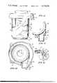
- FIG. 10is a top view of a portion of the water tank and separator assembly.
- FIG. 11is a combined cross-sectional view taken along lines 11--11 of FIG. 10 and a fluid schematic of the fluid system incorporating the principles of the present invention.
- FIG. 12is a back view of the separator housing incorporating the principles of the present invention.
- FIG. 13is a partial cross-section taken along lines 13--13 of FIG. 12.
- FIG. 14is a top view of the separator taken along lines 14--14 of FIG. 3.
- FIG. 15is a top view of the water tank taken along lines 15--15 of FIG. 3.
- FIG. 16is a top view of the waste fluid tank taken along lines 16--16 of FIG. 3.
- FIG. 17is a cross-sectional view of the cam latch device in its unlatched position.
- FIG. 18is a side view of a cleaning fluid cartridge incorporating the principles of the present invention.
- FIG. 19is a top view taken along lines 19--19 of FIG. 18.
- FIG. 20is a cross-sectional view taken along lines 20--20 of FIG. 18.
- FIG. 21is a perspective of a collar incorporating the principles of the present invention.
- FIG. 22is a cross-sectional view of the cartridge and docking port incorporating the principles of the present invention.
- FIG. 23is a cross-sectional view of the suction nozzle taken along lines 23--23 of FIG. 24.
- FIG. 24is a perspective view of the suction nozzle.
- FIGS. 1, 2 and 3A cleaning device according to the present invention is illustrated in FIGS. 1, 2 and 3 as including a frame 30 to which are mounted a pair of wheels 32 by strut 34. As illustrated in FIG. 2, the wheels are in their operable position allowing the cleaning device to move across the surface to be cleaned. For the stored position, the wheels are rotated forward or counter-clockwise in FIG. 2 and comes to rest below the front end of the frame 30. Extending from the top end of the frame 30 is a handle 36 having fluid activation trigger 38 and a spotter actuator 40. Mounted to the front end of the frame is a spray nozzle 42 for projecting cleaning fluid mixtures onto the surface to be cleaned and a suction nozzle 46 mounted to pipe 44 for removing fluids from the surface to be cleaned.
- a water tank 48 and waste fluid or return tank 50are connected as a single unit including a handle 52.
- the tanksare removably mounted to the frame 30 and are secured thereto by a cam latch 54 engaging the bottom of the waste fluid tank 50.
- An upper housing 56 mounted to frame 30 above the tank unitincludes an air fluid separator 58, a motor 60 and a pump or fan 62 as illustrated in FIG. 3.
- An opening 57is provided in the upper housing 56 to view the fluid in the separator 58 which has a transparent body.
- An electrical switch 63activates the motor 60 and an electric cord 65 provides power.
- a container or cartridge of detergent, shampoo or other concentrated cleaning fluid 64 including a collar 66is mounted to docking port 68 in the upper housing 56 as illustrated in FIG. 2.
- the cleaning fluidis mixed with water from the water tank and projected through spray nozzle 42.
- the water tank 48is filled with fluid and mounted to the frame 30 and securely held thereto by cam latch 54.
- a concentrated cleaning fluid cartridge 64is mounted into docking port 68. Now the system is ready for operation.
- the cleaning deviceoperates by activating the motor 63 to turn on the motor to operate the fan and pump 62 to create a force to project a mixture of cleaning fluid and water out of spray nozzle 42 on the surface as well as to create a suction to draw fluid through suction nozzle 46.
- the trigger 38With the trigger 38 in its normal position, no fluid is dispensed. Upon depressing trigger 38, the amount of fluid projected from spray nozzle 42 can be controlled.
- the spotting actuator 40is operated to increase the mixing ratio of detergent to water.
- the dirty or waste fluid from suction nozzle 46is provided to separator 58 wherein the air is separated from the dirty fluid which is provided to waste fluid tank 50.
- the airis provided back through the fan/pump 62 to be re-introduced to the spray nozzle 42.
- the tank assemblyis removed by releasing cam latch 54 and the contents of the waste fluid tank 50 are emptied. This cycle of operation may be repeated.
- the spray nozzle 42which is illustrated in detail in FIG. 4 is an air venturi system which draws a cleaning fluid mixture and projects it onto the cleaning surface.
- Spray nozzle 42includes an air manifold having two complementary pieces 70 and 72 joined along a line or plane 74. See FIG. 2.
- the nozzle of the air manifoldis generally fan-shaped having a plurality of nozzle channels 76 extending therethrough.
- an inlet tube or conduit 78mounted to a source of pressurized air or the output of the fan 62.
- Mounted interior the air manifoldis a fluid manifold 80 having a plurality of fingers 82 extending therefrom and lying in the nozzle channels 76.
- Supports 84 and 85which are integral with the air manifold elements 70 and 72, position the fluid manifold 80 and its fingers 82 central within the air manifold and supports 84 and the nozzle channels 76.
- the fluid manifold 80includes an inlet 86 extending through the back wall of the air manifold and is connected by tubing 88 to the source of a cleaning fluid mixture.
- Air introduced into conduit 78moves through the air manifold around the liquid manifold 80 and fingers 82 and exit nozzle channels 76.
- the restriction of the air through the nozzle channelscreates a venturi effect so as to draw or educe cleaning fluid mixture from the fingers 82 to be forceably ejected onto a surface to be cleaned.
- the source of cleaning fluid mixturebe pressurized so as to maintain an even flow of cleaning mixture fluid to the spray nozzle 42. Since the principle force to draw the cleaning fluid mixture is the venturi effect produced by the air manifold, the pressure provided to the cleaning fluid source is substantially smaller than that provided to the air manifold.
- the cleaning fluid mixture provided to the spray nozzle 42 by tubing 88is from a control switch and mixer illustrated specifically in FIGS. 5-8 and operated by the trigger actuator 40 and the spotting actuator 38 illustrated in detail in FIG. 9.
- a mixing V or connector 90which is mounted to the frame 30 has a mixing outlet connected to tube 88, a water inlet connected to tube 92 and a cleaning fluid inlet connected to tubing 94.
- the water from tube 92 and the cleaning fluid from tube 94are mixed in the V 90 and provided to outlet tube 88.
- Engaging one side of the outlet tube 88is an anvil 96 and adjacent one side of the water inlet tube 92 is an anvil 98.
- a rocker arm 102Pivotally connected to the frame 30 at 100 is a rocker arm 102 having hammers 104 and 106 respectively on opposite sides of the pivot 100.
- a biasing means or spring 108is received in a spring housing 110 on the frame 30 and engages the rocker arm 102 around post 112. The biasing means or spring 108 biases the rocker arm 102 counter-clockwise in FIG. 5.
- a slot 114 in the rocker arm 102receives a control link or wire 116 connected to the spotter actuator 40 and the trigger 38.
- spring 108rotates the rocker arm 102 to its initial position illustrated in FIG. 5 such that hammer 104 is pressed. against anvil 96 completely restricting the tubing 88 at the outlet of the mixer 90. This is illustrated specifically in the cross-section of FIG. 6. In this position, no cleaning fluid mixture is provided to the spray nozzle 42. Thus, if the electric motor is actuated, only air is blown onto the surface to be cleaned. This could produce an air drying if desired.
- the rocker arm 102With movement of the control wire 116 to the right, the rocker arm 102 rotates counter-clockwise moving the hammer 104 away from the anvil 96 so as to begin to open the closed outlet tube 88.
- the flow rate of cleaning fluid mixturecan be controlled.
- the rocker arm 102can be rotated to a position allowing unrestricted flow of the outlet tube 88 as well as unrestricted flow from water inlet tubing 92.
- the rocker arm 102sequentially operates from a first position illustrated in FIG. 5 wherein the outlet is restricted by anvil 96 and hammer 104 for zero flow rate through a first plurality of intermediate angular positions having intermediate restrictions of the outlet to define various flow rates and a second plurality of intermediate angular positions having intermediate restrictions of the water inlet 92 provided by anvil 98 and hammer 106 to define the mixing ratio.
- a single assemblyis provided which controls both the flow rate of dispensing cleaning fluid mixture as well as the mixing ratio of cleaning fluid to water.
- the rocker armcan be reshaped such that hammer 106 will begin to restrict water inlet tube 92 while hammer 104 also restricts outlet tube 88.
- the operation of the rocker arm 102is controlled via wire 116 by the spotting actuator 40 and trigger 38 illustrated in detail in FIG. 9.
- the spotting actuator 40is pivotally mounted to the handle 36 at 120 as is trigger 38.
- the control wire 116is connected to post 122 on spotting actuator 40.
- Post 122lies in a elongated slot 124 in the trigger 38.
- the spotting actuator 40extends from the top of the handle while the trigger 38 extends from the bottom of the handle. This allows activation of either control with the same hand that holds and directs the cleaning device.
- the spotting actuator 40may be controlled by the thumb and the trigger 38 by the other fingers which wrap about the handle 36.
- Counter-clockwise rotation of trigger 38 as illustrated in FIG. 9 from its initial positioncauses counter-clockwise rotation of the spotting actuator 40 and moves the control wire 116 to the right.
- the trigger 38is designed such that the total amount of angular motion which it is capable of travelling is limited to produce via control wire 116 rotation of the rocker arm 102 from the fully restricted condition of outlet tube 88 of mixer 90 to the completely unrestricted condition of outlet tube 88 and no restriction of the water inlet tube 92.
- the restriction of water inlet tube 92 by hammer 106is produced by the further motion by travel produced by spotting actuator 40.
- the counter-clockwise rotation of spotter actuator 40moves the wire 116 further to the right without further motion of trigger 38 since post 122 moves in slot 124.
- spotter actuator 40may be operated independent of trigger 38 because of the slot 124.
- the biasing means 108 of rocker arm 102is sufficiently strong to clamp the outlet tubing 88 and retains the spotting actuator 38 and trigger 40 in their position illustrated in FIG. 9 via wire 116.
- a block 126includes an air port 128 and a water port 130.
- An air inlet nipple 132 and a water outlet nipple 134are provided in the top of water tank 48.
- a tube 136extends down from the water outlet nipple 134 to the bottom of the water tank 48.
- the nipples 132 and 134are received in ports 128 and 130 respectively of the block 126.
- the block 126is mounted to the separator 58 to receive the nipples 132 and 134 during mounting of the tank assembly onto the frame as illustrated in FIG. 10.
- a ball 138 in water port 130acts as a check valve to prevent back flow into the water tank 48.
- first fitting 140Connected to the other end of water port 130 is a first fitting 140 having a main outlet 142 connected to the mixing water inlet tube 92 and a restricted outlet 144.
- the axis of the inlet of fitting 140is coincident with the axis of the restricted outlet 144 and is orthogonal to the main outlet 142 axis.
- the cross-sectional area of main outlet 142is substantially larger than the cross-sectional area of restricted outlet 144.
- the main outletmay have a cross-sectional area four times that of the restricted outlet.
- a primary cleaning fluid inlet 148 of fitting 146is connected to the concentrated cleaning fluid container 64 by tube 150.
- the restricted outlet 144provides a secondary inlet to the second fitting 146.
- the outlet 152 of the second fitting 146is connected to cleaning fluid inlet pipe 94 of the mixer 90.
- the fan or pump 62provides pressurized air via tubing 154 to an input of the concentrated cleaning fluid container 64 and by tubing 156 to water tank 48 via air port 128.
- the primary outlet of pump 62is through conduit 158 to the air manifold of spray nozzle 142.
- the water and the cleaning fluid supply of the systemare pressurized. This produces even control of the fluids such that their mixing ratio and flow rate can be assured.
- the systemalso takes advantage of the natural siphoning effect which results from the venturi spray nozzle 42.
- the pressure provided by pump 62 via tubing 154 and 156 to the concentrated cleaning fluid supply and the water supply respectivelyis small compared to the overall air pressure provided via conduit 158 to the venturi spray nozzle 42.
- the pressure supply via tubing 154 and 156is small, it is very important that it be constant to maintain the desired mixing ratio and flow rates. It should also be noted that by providing the water outlet on the top of tank 48 and the secondary passage 144 of fitting 140 being vertical, the force of gravity helps to further reduce the amount of fluid flowing through restrictive passage 144 into the concentrated cleaning fluid fitting 146.
- FIGS. 3 and 12-14A pump capable of producing the high air flow rate for the venturi spray nozzle as well as a uniform small flow rate for the pressurized water and cleaning fluid containers is illustrated specifically in FIGS. 3 and 12-14.
- the separator 58includes a substantially cylindrical housing 160 with a top rim 162 which forms the housing for the fan or air pump.
- the pressurized air exiting the chamber formed by the wall of the ram 162enters tangentially as illustrated in FIG. 14 to a first portion 163 of primary outlet 164.
- the conduit 158 connected to the venturi spray nozzleis connected to second portion 165 of primary outlet 164.
- a pair of secondary smaller outlets 166 and 168are provided in a wall 169 of the primary outlet 164 and aligned parallel to the flow axis of the second portion of the primary outlet 164.
- the axis of the secondary outlets 166 and 168are perpendicular to the flow axis of the second portion of the primary outlet.
- a ledge or wall 167extends transverse to the flow axis of the second portion 165 of the primary outlet 164 to create a zone of relatively constant pressure compared to the remainder of the primary outlet.
- the secondary outletsare adjacent the ledge 167 in this zone.
- the cross-sectional area of the primary outlet 164is quite substantially larger than the cross-sectional area of the secondary outlets 164 and 166. This particular structure provides a uniform pressure at secondary outlets 166 and 168.
- FIG. 12An air inlet 170 to the separator housing 160 is illustrated in FIG. 12 and provides a flow axis tangential to the cylindrical separator housing 160. This causes a centrifugal flow within the interior.
- a conical shroud 172illustrated in FIG. 3 interior the cylindrical housing 160 has interior thereto an air outlet 174 covered by screen 176.
- the shroud 172 and the outlet 174are an integral part of plate 178 which is mounted to the cylindrical separator housing 160.
- Fluid outlet 180 at the bottom of the cylindrical housingis provided at the bottom of the cylindrical separator housing 160.
- the outlet 174is displaced vertically and horizontally from the lower edge of the conical shroud 172. Dirty fluid and air enter the separator housing 160 through opening 170 and begin a spiraling down and out motion.
- the shroud 172forces the air fluid mixture to the outside of the cylindrical housing or that portion having a greater radius and velocity.
- the area at the entry port 170is not diminished to retard flow of the mixture into the separator chamber while directing the downward moving mixture to the highest velocity portion of the flow thereby maximizing separation of the air and the liquid.
- the heavier fluidmoves towards the cylindrical housing 160 and continues down through outlet 180.
- the lighter airturns a sharp angle and exits through screen 176 and outlet 174 into the fan or pump 62.
- the position of the outlet 174should not be too close to the outer edge of the shroud, otherwise the exiting air will not be completely separated from the fluid.
- the outlet 174is displaced too far from the edge of the shroud, the system will choke.
- the liquid outlet 180 of the separator 58is connected to the waste fluid tank 50 by a conduit 181.
- the tank assembly including fresh water tank 48 and waste fluid tank 50is illustrated in FIGS. 3, 15 and 16.
- the clean water tank 48includes a U-shaped keyway 184 extending along its length.
- the conduit 181connecting the liquid outlet 180 of the separator 58 and the inlet to the return or dirty fluid tank 50.
- air conduit 158providing pressurized air to the spray nozzle and return conduit 173 bringing waste fluid back from the suction nozzle 46.
- the air and fluid conduits 158 and 173respectively form the key for the tank assembly or unit keyways.
- the return tank 50also has a longitudinal U-shaped keyway 185 receiving conduits 158 and 173.
- the conduit 181is flared at 182 at its upper end to provide a funnel and includes a flange 183 extending therefrom to engage the top of the fresh liquid water tank 48 and provide the handle 52 for carrying the tank units.
- the lower end of conduit 181includes a rim 191 which is received in an indenture 188 in the neck 190 extending from the return tank 50 into the keyway 184 of the fresh water tank 48.
- the base 193 of neck 190is rectangular and is received in rectangular shoulder 195 in the bottom of water tank 48.
- the fresh water tank 48has an inlet 186 covered by cap 187 which is secured to the handle 52.
- the waste fluid tank 50is inserted onto the lower end of the clean water tank with the neck 190 extending into the keyway 184 and base 193 in shoulder 195.
- the conduit 181is then inserted from the other end snapping ridge 191 into indenture 188 to mount the conduit to the waste fluid tank and securely mount the clean water tank and the waste fluid tank together. It is evident that the neck 190 and base 193 of the waste fluid tank extending into the keyway and shoulder of the clean water tank 48 stabilizes the tank assembly.
- a portion 192 of keyway 185 of the waste fluid tank 50is inclined to receive a conduit 194 between the fluid return conduit 173 and tube 44 leading to the suction nozzle 46.
- the bottom of the tank 50includes a recess 196 (FIG. 1) having a camming surface 198 therein.
- the cam latch 54lies in the recess 196 and rests against the camming surface 198 of the return tank 50.
- the cam latch 54will be rotated into recess 196 to initially align and ride on camming surface 198 to move the tank assembly along the keys formed by conduits 158 and 173 into alignment with the upper housing 56. This mates the flared portion 182 of conduit 181 with the outlet 180 of the separator 58 as well as nipples 132 and 134 into port 128 and 130 respectively of black 126.
- the cam latch 54includes a substantially L-shaped handle 203 having a camming surface 29 and a lever portion 203.
- the camming surface 201engages the camming surface 198 in the bottom of the waste fluid tank 50.
- the handle 54is pivotally mounted at its lower end at 205 to the block 207 of the frame 30.
- An L-shaped latch 209is pivotally connected at 211 the juncture of the legs to the L-shaped handle 203.
- a spring 213engages the interior of handle 203 and one of the legs of latch 209 to bias the latch counter-clockwise relative to the handle as illustrated in FIGS. 3 and 17.
- a ridge or shoulder 215 in the block 207forms a catch for a leg of latch 209 which acts as a detent to lock the cam latch in the position illustrated in FIG. 3.
- the unlatch position, allowing removal of the tank assembly from the cleaning device,is illustrated in FIG. 17.
- the latch 209In order to release the cam latch 54 from the position illustrated in FIG. 3, the latch 209 is rotated clockwise against the spring 213 with the handle 203 stationary allowing the detent and the latch 209 to ride out of the cam latch or ridge 215 on block 207. The cam latch 54 may then be rotated counter-clockwise.
- the tank assemblyTo mount the tank assembly to the cleaning device, the tank assembly is mounted with the keyways 184 and 185 on the keys formed by conduits 158 and 173 and 194.
- the cam latch 54is rotated back into recess 196 in the bottom of return tank 50 and engages camming surface 198.
- the detent portion of latch 209rides along the exterior edge 217 of block 207 until it exceeds the top thereof and falls into the catch 215.
- the unique cartridge 64 including collar 66is illustrated in FIGS. 18-21.
- the cartridge 64includes a non-circular body 200 having a neck 202 extending therefrom. Threaded portions 204 on neck 202 receives cap 206. A circumferential ridge 208 on neck 202 retains the collar 66 between the top of the cartridge and the ridge 208 such that the collar may rotate relative to the cartridge 64 without any axial motion between the collar and cartridge.
- the sides of the cartridge adjacent the topincludes four indentures 210, 212, 214 and 216. Indentures 210 and 212 receive a handle 218 extending from collar 66 to define two distinct positions of the collar relative to the body.
- the collar 66is in its initial angular position capable of entering into the docking port 68 of the cleaning device. As the collar 66 is rotated counter-clockwise in FIG. 19, the handle will be received in recess 212 which will define a final locked angular position of the collar in the docking port. It should also be noted that the recess 210 allows the handle to be received substantially within the body 200 and therefore allows for easy packaging.
- the collar 66includes a pair of camming recesses 220 therein to receive a pair of tabs in the docking port of the cleaning device.
- Each recess 220includes an entry slot 222 on the top of the collar connected respectively to a inclined portion 224 followed by a horizontal lock portion 226.
- a pair of lugs 260 (FIG. 22) on the docking port 68are received in entry slots 222 and the collar is rotated relative to the body causing the total assembly to move axially without rotation of the cartridge 64.
- the lugs 268ride down the inclined portion 224 along portion 226 to lock the collar and cartridge in place in the docking port.
- the locking portion 226prevents reverse rotation by vibration or use of the cleaning device.
- the collar 66is formed of two portions connected by an integral lying hinge 228. The collar is wrapped around the neck 202 below ridge 208 with latch 232 locking on top of catch 230.
- Indentures 214 and 216receive shoulders or keys in the docking port to align and restrain the cartridge from rotating during axial insertion into the docking port by hand as well as by rotation of the collar 66.
- an insert 234Received in the top opening of the bottle neck 202 is an insert 234 having a pair of nozzles 236 and 238 thereon. As will be explained below, these nozzles are aligned with ports in the docking port with nozzle 236 being an air inlet and nozzle 238 being a fluid outlet.
- the insert 234has a pair of circumferial ridges 240 which engage and seal the insert against the interior of the neck 202. As previously discussed, this is a positive pressure supply system and therefore this seal must be maintained.
- An axial keyway 242is provided in the insert 234 and is received in key 244 running along the interior of the neck 202. This aligns the insert 234 and the nozzles 236 and 238 to the cartridge and consequently to the collar. This assures alignment of the nozzle and the appropriate inlet and outlet of the docking port.
- a tube 246extends from the bottom of the body 200 to the fluid outlet nozzle 238.
- the cartridge 64 in docking port 68is illustrated in detail in FIG. 22.
- the docking partis an assembly which includes a docking housing 250 mounted to the upper housing 56.
- a pair of opposed slots 252are provided in the docking housing 250.
- a U-shaped clip 254is inserted in the docking housing having a pair of nipples 256 and 258 extending through the housing 250 to receive air inlet conduit 154 from the outlet of the pump and cleaning fluid supply tubing 150 leading to the second fitting 146 (See FIG. 11).
- the outer edges of the U-shaped clip 254has tabs 260 which engage the bottom of the slots 252 in the docking housing to maintain the clip therein.
- Extending to the interior of the docking housingare a pair of lugs 262. These lugs form the complementary camming surfaces to be used with the camming recesses 220 in the collar 66.
- a molded rubber sealing disc 264is received in the U-shaped clip 254.
- a clip 254By using a clip 254 to be inserted through the docking housing, it can be made of hard material capable of many insertions on the camming surface. For example, it may be made of Delrin plastic. This reduces the cost of the overall device by making the shaped clip of such expensive material instead of requiring the whole docking housing to be so made.
- the molded rubber seal 264creates an airtight seal since it receives nozzles 236 and 238 on the container and deforms as the container is moved axially within the docking housing.
- a pair of shoulders 266 and 268extend from the housing wall 56 and provide guides or key for indentures 214 and 216 of the cartridge.
- the cartridge 64lies in a chamber in the upper housing 56 with the neck portion 202 extending into a recess portion and the body 200 lying in a cavity portion of the chamber.
- the cavityencompasses at least three of the sides of the body.
- a cartridge 64 of concentrated cleaning fluidmay be mounted to the docking port 68 by aligning the indentures 214 and 216 of the cartridge with shoulders 266 and 268 of the housing respectively.
- the collar 66is placed in its initial or insertion position as defined by the handle 218 lying in indenture 210 of the body.
- the body and collarare moved axially until the lugs 262 of the docking port are received in entry slots 222 in the top of the collar.
- the collar 66is then rotated by handle 218 accessible from the exterior of the cavity causing the body and collar to move axially during rotation of the collar.
- the indentures 214 and 216engage the shoulders 266 and 268 to prevent the cartridge 64 from rotating.
- the collaris rotated to its final or lock position defined by the handle 218 being received in indenture 212 on the body.
- orifices in nozzles 236 and 238are aligned and received with apertures in the base of nipples 256 and 258.
- the insert 234 having a keywayassures alignment of the nozzles with the body and the camming recess 220 of the collar with tabs 262 assure initial alignment as well as indentures 214 and 216 of the body and shoulders 266 and 268 of the housing assure initial alignment of the body and nozzles during the axial movement of the body produced by rotation of the collar 66.
- the suction nozzle 46 of the present invention as illustrated in FIGS. 23 and 24is composed of a front-top piece 270 and a back-bottom piece 272 joined by appropriate fasteners.
- the nozzleincludes a first or inlet passage 274 and a second or outlet passage 276.
- the inlet passage 274is generally U-shaped along a cross-section transverse to the flow axis having a flat bight portion 278 and a pair of short leg portions 280.
- the front flat bight portion 278has a substantially triangular configuration diminishing from the base or nozzle inlet 282 to its juncture 284 with the outlet passage 276. As can be seen from FIG.
- the distance of separation between the front and back portions of the walls of the front and bottom pieces 270 and 272respectively increase from the base or inlet portion 282 to the juncture 284 between the inlet, first passage 274 and the outlet, second passage 276.
- This change of distance of separationcompensates for the diminishing triangular portion of the front and back faces such that the cross-sectional area of the inlet passage 274 is substantially equal along the flow axis. This allows a uniform draw or suction throughout the inlet passage 278 and prevents fluid from hanging up and flowing back out the inlet 282.
- the second passage or outlet passage 276 as illustrated in FIG. 23has a generally triangular cross-section along the flow axis such that its cross-sectional area, transfers to the flow axis, increases along the flow axis.
- a cylindrical connector portion 285receives pipe 44 of the housing.
- the bottom wall 286 of the outlet passageextends diagonally across the connector inlet 284 (See FIG. 3 ).
- the projected axis of the pipe 44 and outlet connector 285intersects the first, inlet passage 278 below the juncture 284 of the inlet and outlet passages 274 and 276, respectively, and forms an oblique angle therewith.
- the outlet passage 276forms a horizontal trough to collect fluid which will drip from the conduits between the nozzle 46 and the fluid separator 58 when the motor and suction system are deactivated. Thus, no fluid will exit the outlet 282 when the device is turned off.
- the top wall 288 of the outlet section 276should be transparent.
- the front, top and sides of the top piece of the nozzle 46are transparent. This allows viewing of the fluid by the user during use. The operator cannot see the front wall of passage 274 since he generally stands behind the device during use.
- the enlarged cross-sectional area of the trough 276causes a pressure drop to slow down the fluid at the juncture or intersection 284.
- the bottom wall 286maintains the fluid adjacent the top wall 288 for better vieweing. When this fluid is slowed down, the exact content and color can be more readily ascertained.
- the fluid from legs 280 on entering the outlet passage 276intersect the primary flow from the bight portion 280 and create eddy currents at their junction. These eddy currents further slow down the fluid in the viewing area.
- the back and bottom walls 272 of the bottom pieceshould be made of non-transparent material. Preferably, they should be white such that additional light may be provided from the back to illuminate the extracted fluids. It should be noted that the outside side walls are extended at 290 to provide a shield for the spray nozzle 42 to prevent water from being sprayed outside the suction nozzle 46.
Landscapes
- Chemical & Material Sciences (AREA)
- Chemical Kinetics & Catalysis (AREA)
- Nozzles (AREA)
Abstract
Description
Claims (19)
Priority Applications (14)
| Application Number | Priority Date | Filing Date | Title |
|---|---|---|---|
| US06/585,547US4570856A (en) | 1984-03-02 | 1984-03-02 | Liquid and detergent mixing chamber and valves |
| DE3486386TDE3486386T2 (en) | 1984-03-02 | 1984-11-02 | Floor washer. |
| EP90202186AEP0404278B1 (en) | 1984-03-02 | 1984-11-02 | Floor washing apparatus |
| EP84904255AEP0174312B1 (en) | 1984-03-02 | 1984-11-02 | Machine for cleaning surfaces such as carpets, floors and the like |
| AT90202186TATE121918T1 (en) | 1984-03-02 | 1984-11-02 | FLOOR WASHER. |
| DE3486370TDE3486370T2 (en) | 1984-03-02 | 1984-11-02 | Device with removable container for cleaning device. |
| AT84904255TATE67082T1 (en) | 1984-03-02 | 1984-11-02 | DEVICE FOR CLEANING SURFACES SUCH AS CARPETS, FLOORS AND LIKE. |
| PCT/US1984/001786WO1985003853A1 (en) | 1984-03-02 | 1984-11-02 | Machine for cleaning surfaces such as carpets, floors and the like |
| AU36718/84AAU3671884A (en) | 1984-03-02 | 1984-11-02 | Machine for cleaning surfaces such as carpets, floors and thelike |
| DE8484904255TDE3485060D1 (en) | 1984-03-02 | 1984-11-02 | DEVICE FOR CLEANING SURFACES LIKE CARPETS, FLOORS AND THE LIKE. |
| EP90202187AEP0404279B1 (en) | 1984-03-02 | 1984-11-02 | Apparatus with removable container for cleaning machine |
| AT90202187TATE118324T1 (en) | 1984-03-02 | 1984-11-02 | DEVICE WITH REMOVABLE CONTAINER FOR CLEANING EQUIPMENT. |
| ZA85182AZA85182B (en) | 1984-03-02 | 1985-01-08 | Machine for cleaning surfaces such as carpets,floors and the like |
| CA000472219ACA1269210A (en) | 1984-03-02 | 1985-01-16 | Machine for cleaning surfaces such as carpets, floors and the like |
Applications Claiming Priority (1)
| Application Number | Priority Date | Filing Date | Title |
|---|---|---|---|
| US06/585,547US4570856A (en) | 1984-03-02 | 1984-03-02 | Liquid and detergent mixing chamber and valves |
Publications (1)
| Publication Number | Publication Date |
|---|---|
| US4570856Atrue US4570856A (en) | 1986-02-18 |
Family
ID=24341921
Family Applications (1)
| Application Number | Title | Priority Date | Filing Date |
|---|---|---|---|
| US06/585,547Expired - LifetimeUS4570856A (en) | 1984-03-02 | 1984-03-02 | Liquid and detergent mixing chamber and valves |
Country Status (2)
| Country | Link |
|---|---|
| US (1) | US4570856A (en) |
| ZA (1) | ZA85182B (en) |
Cited By (39)
| Publication number | Priority date | Publication date | Assignee | Title |
|---|---|---|---|---|
| US5553743A (en)* | 1994-10-27 | 1996-09-10 | Milk Specialties Company | Liquid diet delivery system and control valve for use therein |
| US5567247A (en)* | 1995-02-03 | 1996-10-22 | Armor All Products Corporation | Method for cleaning outdoor painted/artificially stained surface |
| USD399615S (en) | 1997-01-09 | 1998-10-13 | Oreck Holdings, Llc | Steam cleaner |
| US5937475A (en)* | 1995-11-06 | 1999-08-17 | Bissell Inc. | Water extraction cleaning machine with variable solution mixing valve |
| US6073300A (en)* | 1999-01-08 | 2000-06-13 | Royal Appliance Mfg. Co. | Valve assembly for carpet extractor |
| US6095318A (en)* | 1997-07-25 | 2000-08-01 | Scorpio Conveyor Products (Proprietary) Limited | Conveyor scraper and mounting of scraper blade |
| USD429794S (en)* | 1999-09-30 | 2000-08-22 | Griffin Llc | Sprayer collar |
| USD431068S (en)* | 1999-09-30 | 2000-09-19 | Griffin Llc | Sprayer |
| USD432208S (en)* | 1999-10-06 | 2000-10-17 | Griffin Llc | Sprayer system |
| USD433482S (en)* | 1999-09-30 | 2000-11-07 | Griffin Llc | Valve slider |
| USD435087S (en)* | 1999-09-30 | 2000-12-12 | Griffin Llc | Valve seal |
| US6158081A (en)* | 1995-11-06 | 2000-12-12 | Bissell Homecare, Inc. | Water extraction cleaning machine with variable solution mixing valve |
| US6167586B1 (en) | 1995-11-06 | 2001-01-02 | Bissell Homecare, Inc. | Upright water extraction cleaning machine with improved tank structure |
| USD439511S1 (en) | 1999-10-08 | 2001-03-27 | Griffin L.L.C. | Two-part bottle |
| US6283385B1 (en) | 1999-01-22 | 2001-09-04 | Griffin Llc | Method and apparatus for dispensing multiple-component flowable substances |
| US6421862B2 (en) | 1999-06-04 | 2002-07-23 | The Hoover Company | Carpet extractor fluid supply system |
| US20030019071A1 (en)* | 2001-07-30 | 2003-01-30 | Field Bruce F | Cleaner cartridge |
| US6513188B2 (en) | 2001-01-12 | 2003-02-04 | Royal Appliance Mfg. Co. | Mixing pump for carpet extractor |
| US6533871B2 (en) | 2001-01-12 | 2003-03-18 | Royal Appliance Mfg. Co. | Carpet extractor with dual nozzles for dual brushrolls |
| US6585827B2 (en)* | 2001-07-30 | 2003-07-01 | Tennant Company | Apparatus and method of use for cleaning a hard floor surface utilizing an aerated cleaning liquid |
| US20030226230A1 (en)* | 2002-06-07 | 2003-12-11 | The Hoover Company | Liquid distribution system for a cleaning machine |
| US6662600B1 (en) | 2002-08-07 | 2003-12-16 | Tennant Company | Foamed cleaning liquid dispensing system |
| US6671925B2 (en) | 2001-07-30 | 2004-01-06 | Tennant Company | Chemical dispenser for a hard floor surface cleaner |
| USD485175S1 (en) | 2002-05-21 | 2004-01-13 | Tennant Company | Cleaner cartridge |
| US6681442B2 (en) | 2001-05-21 | 2004-01-27 | The Hoover Company | Apparatus and method for cleaning a surface |
| US20040040102A1 (en)* | 2001-07-30 | 2004-03-04 | Tennant Company | Foamed cleaning liquid dispensing system |
| US6735811B2 (en) | 2001-07-30 | 2004-05-18 | Tennant Company | Cleaning liquid dispensing system for a hard floor surface cleaner |
| US20040221407A1 (en)* | 2001-07-30 | 2004-11-11 | Tennant Company | Cleaning liquid dispensing system |
| US20050156059A1 (en)* | 2004-01-15 | 2005-07-21 | Jensen Dale S. | Fluid mixing block |
| US20050217062A1 (en)* | 2001-07-30 | 2005-10-06 | Tennant Company | Air purging of a liquid dispensing system of a surface cleaner |
| US20060137127A1 (en)* | 2001-07-30 | 2006-06-29 | Field Bruce F | Cleaning system utilizing purified water |
| US20060150352A1 (en)* | 2003-09-02 | 2006-07-13 | Tennant Company | Hard and soft floor cleaning tool and machine |
| US20060236494A1 (en)* | 2005-04-07 | 2006-10-26 | Tennant Company | Hard and soft floor surface cleaner |
| US20060282975A1 (en)* | 2005-05-05 | 2006-12-21 | Tennant Company | Floor sweeping and scrubbing machine |
| WO2007032796A2 (en) | 2005-06-10 | 2007-03-22 | Electrolux Home Care Products North America | Sodium bicarbonate vacuum bag inserts |
| US7199711B2 (en) | 2004-11-12 | 2007-04-03 | Tennant Company | Mobile floor cleaner data communication |
| US20070089251A1 (en)* | 2005-10-21 | 2007-04-26 | Tennant Company | Floor cleaner scrub head having a movable disc scrub member |
| US20110219565A1 (en)* | 2003-09-29 | 2011-09-15 | Electrolux Home Care Products North America a Division of Electrolux Home Care Products, Ltd. | Wet Extractor Floor Brush |
| US12239267B2 (en) | 2019-07-02 | 2025-03-04 | Mark Jeffery Giarritta | Four-direction scrubbing carpet shampooer |
Citations (61)
| Publication number | Priority date | Publication date | Assignee | Title |
|---|---|---|---|---|
| US25939A (en)* | 1859-11-01 | Improved method of protecting telegraphic instruments against atmospheric electricity | ||
| US1262717A (en)* | 1917-04-02 | 1918-04-16 | John Vaudreuil | Dish-washing machine. |
| US1458975A (en)* | 1920-09-24 | 1923-06-19 | Friendly Service Co | Mixing apparatus |
| US1632515A (en)* | 1925-12-21 | 1927-06-14 | William M Smith | Sprayer |
| US1713902A (en)* | 1928-05-11 | 1929-05-21 | Hartman Electrical Mfg Company | Sprayer attachment for vacuum cleaners |
| US1726741A (en)* | 1928-01-04 | 1929-09-03 | Leo P Keller | Accessory for vacuum cleaners |
| US1763046A (en)* | 1927-11-28 | 1930-06-10 | Marquette Mfg Co | Automobile washing apparatus |
| US1777453A (en)* | 1928-08-21 | 1930-10-07 | Mcshane Bell Foundry Company | Soap-dispensing faucet |
| US1875729A (en)* | 1927-12-05 | 1932-09-06 | Metal Specialties Mfg Co | Spraying device |
| US1910325A (en)* | 1929-01-21 | 1933-05-23 | Walter S Finnell | Floor mopping machine |
| US1967909A (en)* | 1932-03-18 | 1934-07-24 | Carl J Sonner | Mixing faucet |
| US1988945A (en)* | 1933-07-27 | 1935-01-22 | Ingersoll Rand Co | Controlling device for valves |
| US2094161A (en)* | 1933-11-09 | 1937-09-28 | Ormond H Paddock | Cleaning device |
| US2168692A (en)* | 1936-09-05 | 1939-08-08 | Vidal Charles Henry | Cleaning apparatus |
| US2223963A (en)* | 1938-12-10 | 1940-12-03 | Francis H Nadig | Floor cleaning machine |
| US2243935A (en)* | 1940-05-04 | 1941-06-03 | Williamson James Clarence | Suction head for vacuum cleaners |
| US2345275A (en)* | 1941-02-12 | 1944-03-28 | Thomas L Marvin | Douche appliance |
| US2576669A (en)* | 1949-05-19 | 1951-11-27 | Gen Electric | Rotary valve sprayer |
| US2602699A (en)* | 1947-07-10 | 1952-07-08 | Paul F Otto | Mixing device for water lines |
| US2672366A (en)* | 1951-07-30 | 1954-03-16 | Deport Jacques-Albert Paul | Method and device for charging shower and similar baths with soap emulsion in water |
| US2954576A (en)* | 1958-11-06 | 1960-10-04 | Hoover Co | Suction appliance |
| US2955674A (en)* | 1958-08-08 | 1960-10-11 | Hoover Co | Suction cleaning appliance |
| US2986764A (en)* | 1958-08-08 | 1961-06-06 | Hoover Co | Suction cleaner |
| US2991939A (en)* | 1959-09-28 | 1961-07-11 | Barco Mfg Co Inc | Fluid mixing and spraying device |
| US3002214A (en)* | 1959-12-17 | 1961-10-03 | Hoover Co | Suction floor scrubber |
| US3027034A (en)* | 1958-02-05 | 1962-03-27 | Francis K Christian | Container cap |
| US3040362A (en)* | 1957-04-12 | 1962-06-26 | Hoover Co | Suction cleaning apparatus |
| US3040363A (en)* | 1959-12-14 | 1962-06-26 | Hoover Co | Suction floor washer |
| US3060956A (en)* | 1959-06-10 | 1962-10-30 | Lonn Mfg Co Inc | Proportioning apparatus |
| US3061959A (en)* | 1960-02-25 | 1962-11-06 | Blumenfeld Sylvan | Portable cleaner and presser |
| US3101505A (en)* | 1961-07-18 | 1963-08-27 | Electrolux Corp | Surface treating machine |
| US3207444A (en)* | 1963-08-02 | 1965-09-21 | Dura Corp | Water spray attachment having air control and liquid additive passages connected to a mixing chamber |
| US3208639A (en)* | 1964-05-06 | 1965-09-28 | Finesse Products Inc | Sealed fluid dispensing system for oxidizable fluids |
| US3260464A (en)* | 1963-10-18 | 1966-07-12 | Edward W Harant | Garden chemical solution metering device |
| US3403803A (en)* | 1966-08-31 | 1968-10-01 | Isral J. Markowitz | Safety bottle closure |
| US3426931A (en)* | 1967-06-07 | 1969-02-11 | Robert P Jensen | Safety closure for medicine bottle and the like |
| US3491398A (en)* | 1966-11-15 | 1970-01-27 | Hoover Co | Liquid container latch and mounting arrangement for floor treating machines |
| US3540072A (en)* | 1964-08-03 | 1970-11-17 | Sunbeam Corp | Floor conditioner |
| US3542240A (en)* | 1968-10-14 | 1970-11-24 | Ida Solowey | Partially assembled bulk parenteral solution container and adminstration set |
| US3572964A (en)* | 1969-05-23 | 1971-03-30 | Hoover Co | Motor-pump housing |
| US3572532A (en)* | 1969-08-11 | 1971-03-30 | John J Shannon | Safety closure |
| US3628732A (en)* | 1970-03-19 | 1971-12-21 | Vincent Vicari | Soap mixer and dispenser for shower baths and the like |
| US3752362A (en)* | 1971-12-16 | 1973-08-14 | G Risener | Liquid handling method and apparatus |
| US3801017A (en)* | 1973-02-12 | 1974-04-02 | L & A Prod Inc | Manifold for high pressure washer in mechanical mode selection |
| US3883301A (en)* | 1973-06-21 | 1975-05-13 | U S Floor Systems Inc | Method of cleaning textile fabrics |
| US3896521A (en)* | 1973-03-27 | 1975-07-29 | Parise & Sons Inc | Home cleaning system |
| US3926327A (en)* | 1974-01-26 | 1975-12-16 | Hofmann Metall Kunststoff | Safety and security closure |
| US3939527A (en)* | 1973-10-12 | 1976-02-24 | Clarke-Gravely Corporation | Portable surface cleaner |
| US3940826A (en)* | 1973-10-12 | 1976-03-02 | Clarke-Gravely Corporation | Portable surface cleaner |
| US3959844A (en)* | 1975-02-05 | 1976-06-01 | Chemko Industries, Inc. | Carpet soil extractor |
| US3974541A (en)* | 1973-11-01 | 1976-08-17 | Silvis Donahue B | Apparatus for cleaning a floor cover |
| US4011288A (en)* | 1975-03-14 | 1977-03-08 | Baxter Travenol Laboratories, Inc. | Disposable humidifier assembly |
| US4114229A (en)* | 1971-06-30 | 1978-09-19 | Clarke-Gravely Corporation | Surface cleaning apparatus |
| US4137930A (en)* | 1977-01-26 | 1979-02-06 | Scholle Corporation | Single operation normally closed coupling valve |
| US4197942A (en)* | 1975-09-03 | 1980-04-15 | Picker Corporation | Containerized fluid supply for fluid mixing and dispensing system |
| US4214675A (en)* | 1978-02-27 | 1980-07-29 | Schmit Justin M | Liquid pouch in a carton with a pouring spout |
| US4236651A (en)* | 1976-06-08 | 1980-12-02 | Trisa Burstenfabrik A.G. | Dispenser device with valve piston pump |
| US4281775A (en)* | 1979-01-15 | 1981-08-04 | Turner Frank J | Can tapping valve apparatus |
| US4296786A (en)* | 1979-09-28 | 1981-10-27 | The West Company | Transfer device for use in mixing a primary solution and a secondary or additive substance |
| US4314673A (en)* | 1980-05-23 | 1982-02-09 | Universal-Rundle Corporation | Mixing faucet valve with diverter and stop check system |
| US4333203A (en)* | 1980-04-23 | 1982-06-08 | Bissell, Inc. | Conversion attachment for a wet-dry vacuum cleaner |
- 1984
- 1984-03-02USUS06/585,547patent/US4570856A/ennot_activeExpired - Lifetime
- 1985
- 1985-01-08ZAZA85182Apatent/ZA85182B/enunknown
Patent Citations (63)
| Publication number | Priority date | Publication date | Assignee | Title |
|---|---|---|---|---|
| US25939A (en)* | 1859-11-01 | Improved method of protecting telegraphic instruments against atmospheric electricity | ||
| US1262717A (en)* | 1917-04-02 | 1918-04-16 | John Vaudreuil | Dish-washing machine. |
| US1458975A (en)* | 1920-09-24 | 1923-06-19 | Friendly Service Co | Mixing apparatus |
| US1632515A (en)* | 1925-12-21 | 1927-06-14 | William M Smith | Sprayer |
| US1763046A (en)* | 1927-11-28 | 1930-06-10 | Marquette Mfg Co | Automobile washing apparatus |
| US1875729A (en)* | 1927-12-05 | 1932-09-06 | Metal Specialties Mfg Co | Spraying device |
| US1726741A (en)* | 1928-01-04 | 1929-09-03 | Leo P Keller | Accessory for vacuum cleaners |
| US1713902A (en)* | 1928-05-11 | 1929-05-21 | Hartman Electrical Mfg Company | Sprayer attachment for vacuum cleaners |
| US1777453A (en)* | 1928-08-21 | 1930-10-07 | Mcshane Bell Foundry Company | Soap-dispensing faucet |
| US1910325A (en)* | 1929-01-21 | 1933-05-23 | Walter S Finnell | Floor mopping machine |
| US1967909A (en)* | 1932-03-18 | 1934-07-24 | Carl J Sonner | Mixing faucet |
| US1988945A (en)* | 1933-07-27 | 1935-01-22 | Ingersoll Rand Co | Controlling device for valves |
| US2094161A (en)* | 1933-11-09 | 1937-09-28 | Ormond H Paddock | Cleaning device |
| US2168692A (en)* | 1936-09-05 | 1939-08-08 | Vidal Charles Henry | Cleaning apparatus |
| US2223963A (en)* | 1938-12-10 | 1940-12-03 | Francis H Nadig | Floor cleaning machine |
| US2243935A (en)* | 1940-05-04 | 1941-06-03 | Williamson James Clarence | Suction head for vacuum cleaners |
| US2345275A (en)* | 1941-02-12 | 1944-03-28 | Thomas L Marvin | Douche appliance |
| US2602699A (en)* | 1947-07-10 | 1952-07-08 | Paul F Otto | Mixing device for water lines |
| US2576669A (en)* | 1949-05-19 | 1951-11-27 | Gen Electric | Rotary valve sprayer |
| US2672366A (en)* | 1951-07-30 | 1954-03-16 | Deport Jacques-Albert Paul | Method and device for charging shower and similar baths with soap emulsion in water |
| USRE25939E (en) | 1957-04-12 | 1965-12-14 | Unitary floor scrubbing and drying | |
| US3040362A (en)* | 1957-04-12 | 1962-06-26 | Hoover Co | Suction cleaning apparatus |
| US3027034A (en)* | 1958-02-05 | 1962-03-27 | Francis K Christian | Container cap |
| US2955674A (en)* | 1958-08-08 | 1960-10-11 | Hoover Co | Suction cleaning appliance |
| US2986764A (en)* | 1958-08-08 | 1961-06-06 | Hoover Co | Suction cleaner |
| US2954576A (en)* | 1958-11-06 | 1960-10-04 | Hoover Co | Suction appliance |
| US3060956A (en)* | 1959-06-10 | 1962-10-30 | Lonn Mfg Co Inc | Proportioning apparatus |
| US2991939A (en)* | 1959-09-28 | 1961-07-11 | Barco Mfg Co Inc | Fluid mixing and spraying device |
| US3040363A (en)* | 1959-12-14 | 1962-06-26 | Hoover Co | Suction floor washer |
| US3002214A (en)* | 1959-12-17 | 1961-10-03 | Hoover Co | Suction floor scrubber |
| US3061959A (en)* | 1960-02-25 | 1962-11-06 | Blumenfeld Sylvan | Portable cleaner and presser |
| US3101505A (en)* | 1961-07-18 | 1963-08-27 | Electrolux Corp | Surface treating machine |
| US3207444A (en)* | 1963-08-02 | 1965-09-21 | Dura Corp | Water spray attachment having air control and liquid additive passages connected to a mixing chamber |
| US3260464A (en)* | 1963-10-18 | 1966-07-12 | Edward W Harant | Garden chemical solution metering device |
| US3208639A (en)* | 1964-05-06 | 1965-09-28 | Finesse Products Inc | Sealed fluid dispensing system for oxidizable fluids |
| US3540072A (en)* | 1964-08-03 | 1970-11-17 | Sunbeam Corp | Floor conditioner |
| US3403803A (en)* | 1966-08-31 | 1968-10-01 | Isral J. Markowitz | Safety bottle closure |
| US3491398A (en)* | 1966-11-15 | 1970-01-27 | Hoover Co | Liquid container latch and mounting arrangement for floor treating machines |
| US3426931A (en)* | 1967-06-07 | 1969-02-11 | Robert P Jensen | Safety closure for medicine bottle and the like |
| US3542240A (en)* | 1968-10-14 | 1970-11-24 | Ida Solowey | Partially assembled bulk parenteral solution container and adminstration set |
| US3572964A (en)* | 1969-05-23 | 1971-03-30 | Hoover Co | Motor-pump housing |
| US3572532A (en)* | 1969-08-11 | 1971-03-30 | John J Shannon | Safety closure |
| US3628732A (en)* | 1970-03-19 | 1971-12-21 | Vincent Vicari | Soap mixer and dispenser for shower baths and the like |
| US4114229A (en)* | 1971-06-30 | 1978-09-19 | Clarke-Gravely Corporation | Surface cleaning apparatus |
| US3752362A (en)* | 1971-12-16 | 1973-08-14 | G Risener | Liquid handling method and apparatus |
| US3801017A (en)* | 1973-02-12 | 1974-04-02 | L & A Prod Inc | Manifold for high pressure washer in mechanical mode selection |
| US3896521A (en)* | 1973-03-27 | 1975-07-29 | Parise & Sons Inc | Home cleaning system |
| US3883301A (en)* | 1973-06-21 | 1975-05-13 | U S Floor Systems Inc | Method of cleaning textile fabrics |
| US3939527A (en)* | 1973-10-12 | 1976-02-24 | Clarke-Gravely Corporation | Portable surface cleaner |
| US3940826A (en)* | 1973-10-12 | 1976-03-02 | Clarke-Gravely Corporation | Portable surface cleaner |
| US3974541A (en)* | 1973-11-01 | 1976-08-17 | Silvis Donahue B | Apparatus for cleaning a floor cover |
| US3926327A (en)* | 1974-01-26 | 1975-12-16 | Hofmann Metall Kunststoff | Safety and security closure |
| US3959844A (en)* | 1975-02-05 | 1976-06-01 | Chemko Industries, Inc. | Carpet soil extractor |
| US4011288A (en)* | 1975-03-14 | 1977-03-08 | Baxter Travenol Laboratories, Inc. | Disposable humidifier assembly |
| US4197942A (en)* | 1975-09-03 | 1980-04-15 | Picker Corporation | Containerized fluid supply for fluid mixing and dispensing system |
| US4197942B1 (en)* | 1975-09-03 | 1984-09-04 | ||
| US4236651A (en)* | 1976-06-08 | 1980-12-02 | Trisa Burstenfabrik A.G. | Dispenser device with valve piston pump |
| US4137930A (en)* | 1977-01-26 | 1979-02-06 | Scholle Corporation | Single operation normally closed coupling valve |
| US4214675A (en)* | 1978-02-27 | 1980-07-29 | Schmit Justin M | Liquid pouch in a carton with a pouring spout |
| US4281775A (en)* | 1979-01-15 | 1981-08-04 | Turner Frank J | Can tapping valve apparatus |
| US4296786A (en)* | 1979-09-28 | 1981-10-27 | The West Company | Transfer device for use in mixing a primary solution and a secondary or additive substance |
| US4333203A (en)* | 1980-04-23 | 1982-06-08 | Bissell, Inc. | Conversion attachment for a wet-dry vacuum cleaner |
| US4314673A (en)* | 1980-05-23 | 1982-02-09 | Universal-Rundle Corporation | Mixing faucet valve with diverter and stop check system |
Cited By (55)
| Publication number | Priority date | Publication date | Assignee | Title |
|---|---|---|---|---|
| US5553743A (en)* | 1994-10-27 | 1996-09-10 | Milk Specialties Company | Liquid diet delivery system and control valve for use therein |
| US5567247A (en)* | 1995-02-03 | 1996-10-22 | Armor All Products Corporation | Method for cleaning outdoor painted/artificially stained surface |
| US6158081A (en)* | 1995-11-06 | 2000-12-12 | Bissell Homecare, Inc. | Water extraction cleaning machine with variable solution mixing valve |
| US5937475A (en)* | 1995-11-06 | 1999-08-17 | Bissell Inc. | Water extraction cleaning machine with variable solution mixing valve |
| US6167586B1 (en) | 1995-11-06 | 2001-01-02 | Bissell Homecare, Inc. | Upright water extraction cleaning machine with improved tank structure |
| USD399615S (en) | 1997-01-09 | 1998-10-13 | Oreck Holdings, Llc | Steam cleaner |
| US6095318A (en)* | 1997-07-25 | 2000-08-01 | Scorpio Conveyor Products (Proprietary) Limited | Conveyor scraper and mounting of scraper blade |
| US6073300A (en)* | 1999-01-08 | 2000-06-13 | Royal Appliance Mfg. Co. | Valve assembly for carpet extractor |
| US6283385B1 (en) | 1999-01-22 | 2001-09-04 | Griffin Llc | Method and apparatus for dispensing multiple-component flowable substances |
| US6421862B2 (en) | 1999-06-04 | 2002-07-23 | The Hoover Company | Carpet extractor fluid supply system |
| USD435087S (en)* | 1999-09-30 | 2000-12-12 | Griffin Llc | Valve seal |
| USD433482S (en)* | 1999-09-30 | 2000-11-07 | Griffin Llc | Valve slider |
| USD431068S (en)* | 1999-09-30 | 2000-09-19 | Griffin Llc | Sprayer |
| USD429794S (en)* | 1999-09-30 | 2000-08-22 | Griffin Llc | Sprayer collar |
| USD432208S (en)* | 1999-10-06 | 2000-10-17 | Griffin Llc | Sprayer system |
| USD439511S1 (en) | 1999-10-08 | 2001-03-27 | Griffin L.L.C. | Two-part bottle |
| US6836928B2 (en) | 2001-01-12 | 2005-01-04 | Royal Appliance Mfg. Co. | Mixing pump for carpet extractor |
| US6513188B2 (en) | 2001-01-12 | 2003-02-04 | Royal Appliance Mfg. Co. | Mixing pump for carpet extractor |
| US6533871B2 (en) | 2001-01-12 | 2003-03-18 | Royal Appliance Mfg. Co. | Carpet extractor with dual nozzles for dual brushrolls |
| US20030110588A1 (en)* | 2001-01-12 | 2003-06-19 | Royal Appliance Mfg. Co. | Mixing pump for carpet extractor |
| US6681442B2 (en) | 2001-05-21 | 2004-01-27 | The Hoover Company | Apparatus and method for cleaning a surface |
| US20040040102A1 (en)* | 2001-07-30 | 2004-03-04 | Tennant Company | Foamed cleaning liquid dispensing system |
| US20040221407A1 (en)* | 2001-07-30 | 2004-11-11 | Tennant Company | Cleaning liquid dispensing system |
| US6671925B2 (en) | 2001-07-30 | 2004-01-06 | Tennant Company | Chemical dispenser for a hard floor surface cleaner |
| US20060137127A1 (en)* | 2001-07-30 | 2006-06-29 | Field Bruce F | Cleaning system utilizing purified water |
| US7051399B2 (en) | 2001-07-30 | 2006-05-30 | Tennant Company | Cleaner cartridge |
| US6585827B2 (en)* | 2001-07-30 | 2003-07-01 | Tennant Company | Apparatus and method of use for cleaning a hard floor surface utilizing an aerated cleaning liquid |
| US6705332B2 (en) | 2001-07-30 | 2004-03-16 | Tennant Company | Hard floor surface cleaner utilizing an aerated cleaning liquid |
| US6735811B2 (en) | 2001-07-30 | 2004-05-18 | Tennant Company | Cleaning liquid dispensing system for a hard floor surface cleaner |
| US20040187895A1 (en)* | 2001-07-30 | 2004-09-30 | Tennant Company | Chemical dispensing method for a hard surface cleaner |
| US7172658B2 (en) | 2001-07-30 | 2007-02-06 | Tennant Company | Cleaning liquid dispensing in a mobile hard surface cleaner |
| US20030019071A1 (en)* | 2001-07-30 | 2003-01-30 | Field Bruce F | Cleaner cartridge |
| US8051861B2 (en) | 2001-07-30 | 2011-11-08 | Tennant Company | Cleaning system utilizing purified water |
| US20050217062A1 (en)* | 2001-07-30 | 2005-10-06 | Tennant Company | Air purging of a liquid dispensing system of a surface cleaner |
| US20060032519A1 (en)* | 2001-07-30 | 2006-02-16 | Tennant Company | Cleaning liquid dispensing in a mobile hard surface cleaner |
| USD485175S1 (en) | 2002-05-21 | 2004-01-13 | Tennant Company | Cleaner cartridge |
| US20030226230A1 (en)* | 2002-06-07 | 2003-12-11 | The Hoover Company | Liquid distribution system for a cleaning machine |
| US7617563B2 (en) | 2002-06-07 | 2009-11-17 | Healthy Gain Investments Limited | Liquid distribution system for a cleaning machine |
| US6662600B1 (en) | 2002-08-07 | 2003-12-16 | Tennant Company | Foamed cleaning liquid dispensing system |
| US20060150352A1 (en)* | 2003-09-02 | 2006-07-13 | Tennant Company | Hard and soft floor cleaning tool and machine |
| US8028365B2 (en) | 2003-09-02 | 2011-10-04 | Tennant Company | Hard and soft floor cleaning tool and machine |
| US8448293B2 (en) | 2003-09-29 | 2013-05-28 | Electrolux Home Care Products, Inc. | Wet extractor floor brush |
| US20110219565A1 (en)* | 2003-09-29 | 2011-09-15 | Electrolux Home Care Products North America a Division of Electrolux Home Care Products, Ltd. | Wet Extractor Floor Brush |
| US7059541B2 (en) | 2004-01-15 | 2006-06-13 | Harris Research, Inc. | Fluid mixing block |
| US20050156059A1 (en)* | 2004-01-15 | 2005-07-21 | Jensen Dale S. | Fluid mixing block |
| US7199711B2 (en) | 2004-11-12 | 2007-04-03 | Tennant Company | Mobile floor cleaner data communication |
| US20060236494A1 (en)* | 2005-04-07 | 2006-10-26 | Tennant Company | Hard and soft floor surface cleaner |
| US7448114B2 (en) | 2005-05-05 | 2008-11-11 | Tennant Company | Floor sweeping and scrubbing machine |
| US7665174B2 (en) | 2005-05-05 | 2010-02-23 | Tennant Company | Cleaning head for use in a floor cleaning machine |
| US20060282975A1 (en)* | 2005-05-05 | 2006-12-21 | Tennant Company | Floor sweeping and scrubbing machine |
| US20060282965A1 (en)* | 2005-05-05 | 2006-12-21 | Tennant Company | Cleaning head for use in a floor cleaning machine |
| WO2007032796A2 (en) | 2005-06-10 | 2007-03-22 | Electrolux Home Care Products North America | Sodium bicarbonate vacuum bag inserts |
| US20070089251A1 (en)* | 2005-10-21 | 2007-04-26 | Tennant Company | Floor cleaner scrub head having a movable disc scrub member |
| US8584294B2 (en) | 2005-10-21 | 2013-11-19 | Tennant Company | Floor cleaner scrub head having a movable disc scrub member |
| US12239267B2 (en) | 2019-07-02 | 2025-03-04 | Mark Jeffery Giarritta | Four-direction scrubbing carpet shampooer |
Also Published As
| Publication number | Publication date |
|---|---|
| ZA85182B (en) | 1985-11-27 |
Similar Documents
| Publication | Publication Date | Title |
|---|---|---|
| US4570856A (en) | Liquid and detergent mixing chamber and valves | |
| US4558484A (en) | Tank unit for cleaning devices | |
| US4559665A (en) | Indicator nozzle for cleaning devices | |
| US4676287A (en) | Cartridge and docking port for a cleaning device | |
| US4566149A (en) | Cam latch for cleaning devices | |
| US4712740A (en) | Venturi spray nozzle for a cleaning device | |
| EP0174312B1 (en) | Machine for cleaning surfaces such as carpets, floors and the like | |
| US4558823A (en) | Spotting control and trigger assembly | |
| US4575007A (en) | Mixing control for water and cleaning fluid | |
| CA1269210A (en) | Machine for cleaning surfaces such as carpets, floors and the like | |
| US10850241B2 (en) | Multiple function dispenser | |
| JP3542609B2 (en) | Improved spray device | |
| JP3818746B2 (en) | Dilution use solution injection device | |
| US7017621B2 (en) | Container filling apparatus and methods | |
| CA1212086A (en) | Variable dilution ratio hose-end sprayer | |
| US4559667A (en) | Dripless nozzle for a cleaning device | |
| US4559666A (en) | Air-liquid separator for cleaning devices | |
| MXPA97002156A (en) | Vacuum d | |
| US4341350A (en) | Chemical injection system for high pressure washers | |
| US3445067A (en) | Eductor type proportioner | |
| EP1289667B1 (en) | Dispensing and Rinsing Gun | |
| US5715877A (en) | Solution dilution assembly | |
| US5799361A (en) | Cleaning solution applicator | |
| CA1299825C (en) | Cleaning device with suction nozzle and liquid and gas separator | |
| CA1334473C (en) | Cleaning device with suction nozzle and liquid and gas separator |
Legal Events
| Date | Code | Title | Description |
|---|---|---|---|
| AS | Assignment | Owner name:GENERAL SIGNAL CORPORATION A NY CORP Free format text:ASSIGNMENT OF ASSIGNORS INTEREST.;ASSIGNORS:GROTH, HUGH F.;COLLINS, JOHN M.;REEL/FRAME:004237/0459 Effective date:19840228 | |
| AS | Assignment | Owner name:NEW REGINA CORPORATION A DE CORP. Free format text:ASSIGNMENT OF ASSIGNORS INTEREST.;ASSIGNOR:GENERAL SIGNAL CORPORATION A NY CORP.;REEL/FRAME:004288/0896 Effective date:19840629 Owner name:NEW REGINA CORPORATION Free format text:ASSIGNMENT OF ASSIGNORS INTEREST;ASSIGNOR:GENERAL SIGNAL CORPORATION A NY CORP.;REEL/FRAME:004288/0896 Effective date:19840629 | |
| STCF | Information on status: patent grant | Free format text:PATENTED CASE | |
| AS | Assignment | Owner name:PHILADELPHIA NATIONAL BANK, THE, PENNSYLVANIA Free format text:SECURITY INTEREST;ASSIGNOR:NEW REGINA COMPANY, INC.;REEL/FRAME:005024/0593 Effective date:19890224 Owner name:NEW REGINA CORPORATION Free format text:LETTERS OF ADMINISTRATION;ASSIGNOR:GENERAL SIGNAL APPLIANCE CORP.;REEL/FRAME:005027/0165 Effective date:19840629 Owner name:CHASE MANHATTAN BANK, N.A., THE, PENNSYLVANIA Free format text:SECURITY INTEREST;ASSIGNOR:NEW REGINA COMPANY, INC.;REEL/FRAME:005024/0593 Effective date:19890224 Owner name:REGINA COMPANY, INC., THE Free format text:ASSIGNMENT OF ASSIGNORS INTEREST. FILED SEPTEMBER 18, 1985;ASSIGNOR:NEW REGINA CORPORATION;REEL/FRAME:005027/0178 Effective date:19850917 | |
| FPAY | Fee payment | Year of fee payment:4 | |
| AS | Assignment | Owner name:TRC ACQUISITION CORPORATION Free format text:RELEASED BY SECURED PARTY;ASSIGNORS:CHASE MANHATTAN BANK, N.A., THE;PHILADELPHIA NATIONAL BANK, INDIVIDUALLY AND AS AGENT FOR ITSELF AND FOR THE CHASE MANHATTAN;REEL/FRAME:005129/0512 Effective date:19890630 | |
| AS | Assignment | Owner name:FIRST NATIONAL BANK OF BOSTON, THE, MASSACHUSETTS Free format text:SECURITY INTEREST;ASSIGNOR:TRC ACQUISITION CORPORATION;REEL/FRAME:005184/0068 Effective date:19890630 | |
| AS | Assignment | Owner name:BANCBOSTON INVESTMENTS INC. Free format text:SECURITY INTEREST;ASSIGNOR:TRC ACQUISITION CORPORATION;REEL/FRAME:005175/0535 Effective date:19891024 Owner name:WELLS FARGO & CO. Free format text:SECURITY INTEREST;ASSIGNOR:TRC ACQUISITION CORPORATION;REEL/FRAME:005175/0535 Effective date:19891024 Owner name:FIRST BOSTON MEZZANINE INVESTMENT PARTNERSHIP-9 Free format text:SECURITY INTEREST;ASSIGNOR:TRC ACQUISITION CORPORATION;REEL/FRAME:005175/0535 Effective date:19891024 Owner name:WESRAY CAPITAL CORPORATION Free format text:SECURITY INTEREST;ASSIGNOR:TRC ACQUISITION CORPORATION;REEL/FRAME:005175/0535 Effective date:19891024 Owner name:FIRST BOSTON SECURITIES CORPORATION Free format text:SECURITY INTEREST;ASSIGNOR:TRC ACQUISITION CORPORATION;REEL/FRAME:005175/0535 Effective date:19891024 | |
| AS | Assignment | Owner name:FIRST BOSTON SECURITIES CORPORATION Free format text:SECURITY INTEREST;ASSIGNOR:TRC ACQUISITION CORPORATION;REEL/FRAME:005250/0034 Effective date:19891024 Owner name:BANCBOSTON INVESTMENTS INC. Free format text:SECURITY INTEREST;ASSIGNOR:TRC ACQUISITION CORPORATION;REEL/FRAME:005250/0034 Effective date:19891024 Owner name:WESRAY CAPITAL CORPORATION Free format text:SECURITY INTEREST;ASSIGNOR:TRC ACQUISITION CORPORATION;REEL/FRAME:005250/0034 Effective date:19891024 Owner name:WELLS FARGO & COMPANY Free format text:SECURITY INTEREST;ASSIGNOR:TRC ACQUISITION CORPORATION;REEL/FRAME:005250/0034 Effective date:19891024 Owner name:FIRST BOSTON MEZZANINE INVESTMENT PARTNERSHIP Free format text:SECURITY INTEREST;ASSIGNOR:TRC ACQUISITION CORPORATION;REEL/FRAME:005250/0034 Effective date:19891024 | |
| AS | Assignment | Owner name:CONGRESS FINANCIAL CORPORATION Free format text:SECURITY INTEREST;ASSIGNOR:TRC ACQUISITION CORPORATION, A CORP. OF DE;REEL/FRAME:005877/0073 Effective date:19910808 | |
| FEPP | Fee payment procedure | Free format text:PAYOR NUMBER ASSIGNED (ORIGINAL EVENT CODE: ASPN); ENTITY STATUS OF PATENT OWNER: LARGE ENTITY | |
| FPAY | Fee payment | Year of fee payment:8 | |
| AS | Assignment | Owner name:PHILIPS ELECTRONICS NORTH AMERICA CORPORATION, NEW Free format text:ASSIGNMENT OF ASSIGNORS INTEREST;ASSIGNORS:REGINA COMPANY, THE;REGINA CONSUMER PRODUCTS,INC.;REEL/FRAME:007534/0166 Effective date:19950515 | |
| FPAY | Fee payment | Year of fee payment:12 | |
| AS | Assignment | Owner name:ORECK MANUFACTURING COMPANY, MISSISSIPPI Free format text:CHANGE OF NAME;ASSIGNOR:REGINA HOME CARE CORPORATION;REEL/FRAME:008683/0909 Effective date:19970623 Owner name:REGINA HOME CARE CORPORATION, MISSISSIPPI Free format text:ASSIGNMENT OF ASSIGNORS INTEREST;ASSIGNOR:PHILIPS ELECTRONICS NORTH AMERICA CORPORATION;REEL/FRAME:008698/0537 Effective date:19970228 | |
| AS | Assignment | Owner name:ORECK HOLDINGS, LLC, WYOMING Free format text:ASSIGNMENT OF ASSIGNORS INTEREST;ASSIGNOR:ORECK MANUFACTURING COMPANY;REEL/FRAME:008896/0903 Effective date:19971202 | |
| AS | Assignment | Owner name:BANK ONE, LOUISIANA Free format text:SECURITY INTEREST;ASSIGNORS:ORECK CORPORATION;ORECK HOLDINGS, LLC;REEL/FRAME:010310/0630 Effective date:19990225 Owner name:BANK ONE, LOUISIANA Free format text:SECURITY AGREEMENT. RE-RECORD TO CORRECT THE NUMBER OF MICROFILM PAGES FROM 18 TO 20 AT REEL 9808 FRAME 0487, AND TO ADD ASSIGNOR.;ASSIGNORS:ORECK CORPORATION;CHECK HOLDINGS, LLC.;REEL/FRAME:009808/0487 Effective date:19990225 | |
| AS | Assignment | Owner name:ROYAL BANK OF SCOTLAND PLC, THE, NEW YORK Free format text:SECURITY AGREEMENT;ASSIGNORS:ASP ORECK II INC.;ORECK CORPORATION;HOKY HOLDINGS, LLC;AND OTHERS;REEL/FRAME:014227/0573 Effective date:20030411 | |
| AS | Assignment | Owner name:ORECK CORPORATION, LOUISIANA Free format text:RELEASE OF SECURITY INTEREST AT REEL/FRAME NO. 14227/0573;ASSIGNOR:THE ROYAL BANK OF SCOTLAND PLC;REEL/FRAME:015711/0103 Effective date:20050202 Owner name:HOKY HOLDINGS, LLC, LOUISIANA Free format text:RELEASE OF SECURITY INTEREST AT REEL/FRAME NO. 14227/0573;ASSIGNOR:THE ROYAL BANK OF SCOTLAND PLC;REEL/FRAME:015711/0103 Effective date:20050202 Owner name:ORECK@HOME, LLC, LOUISIANA Free format text:RELEASE OF SECURITY INTEREST AT REEL/FRAME NO. 14227/0573;ASSIGNOR:THE ROYAL BANK OF SCOTLAND PLC;REEL/FRAME:015711/0103 Effective date:20050202 Owner name:ORECK AUSTRALIA, LTD., LOUISIANA Free format text:RELEASE OF SECURITY INTEREST AT REEL/FRAME NO. 14227/0573;ASSIGNOR:THE ROYAL BANK OF SCOTLAND PLC;REEL/FRAME:015711/0103 Effective date:20050202 Owner name:ORECK DIRECT, LLC, LOUISIANA Free format text:RELEASE OF SECURITY INTEREST AT REEL/FRAME NO. 14227/0573;ASSIGNOR:THE ROYAL BANK OF SCOTLAND PLC;REEL/FRAME:015711/0103 Effective date:20050202 Owner name:ORECK FINANCIAL SERVICES, LLC, LOUISIANA Free format text:RELEASE OF SECURITY INTEREST AT REEL/FRAME NO. 14227/0573;ASSIGNOR:THE ROYAL BANK OF SCOTLAND PLC;REEL/FRAME:015711/0103 Effective date:20050202 Owner name:ORECK HOLDINGS, LLC, LOUISIANA Free format text:RELEASE OF SECURITY INTEREST AT REEL/FRAME NO. 14227/0573;ASSIGNOR:THE ROYAL BANK OF SCOTLAND PLC;REEL/FRAME:015711/0103 Effective date:20050202 Owner name:ORECK HOMECARE, LLC, LOUISIANA Free format text:RELEASE OF SECURITY INTEREST AT REEL/FRAME NO. 14227/0573;ASSIGNOR:THE ROYAL BANK OF SCOTLAND PLC;REEL/FRAME:015711/0103 Effective date:20050202 Owner name:ORECK HOSPITALITY INC., LOUISIANA Free format text:RELEASE OF SECURITY INTEREST AT REEL/FRAME NO. 14227/0573;ASSIGNOR:THE ROYAL BANK OF SCOTLAND PLC;REEL/FRAME:015711/0103 Effective date:20050202 Owner name:ORECK MANUFACTURING COMPANY, LOUISIANA Free format text:RELEASE OF SECURITY INTEREST AT REEL/FRAME NO. 14227/0573;ASSIGNOR:THE ROYAL BANK OF SCOTLAND PLC;REEL/FRAME:015711/0103 Effective date:20050202 Owner name:ORECK MARKETING, LTD., LOUISIANA Free format text:RELEASE OF SECURITY INTEREST AT REEL/FRAME NO. 14227/0573;ASSIGNOR:THE ROYAL BANK OF SCOTLAND PLC;REEL/FRAME:015711/0103 Effective date:20050202 Owner name:ORECK MERCHANDISING, LLC, LOUISIANA Free format text:RELEASE OF SECURITY INTEREST AT REEL/FRAME NO. 14227/0573;ASSIGNOR:THE ROYAL BANK OF SCOTLAND PLC;REEL/FRAME:015711/0103 Effective date:20050202 Owner name:ORECK SALES, LLC, LOUISIANA Free format text:RELEASE OF SECURITY INTEREST AT REEL/FRAME NO. 14227/0573;ASSIGNOR:THE ROYAL BANK OF SCOTLAND PLC;REEL/FRAME:015711/0103 Effective date:20050202 Owner name:REGINA HOLDINGS, LLC, LOUISIANA Free format text:RELEASE OF SECURITY INTEREST AT REEL/FRAME NO. 14227/0573;ASSIGNOR:THE ROYAL BANK OF SCOTLAND PLC;REEL/FRAME:015711/0103 Effective date:20050202 Owner name:REGINA HOME CARE, LLC, LOUISIANA Free format text:RELEASE OF SECURITY INTEREST AT REEL/FRAME NO. 14227/0573;ASSIGNOR:THE ROYAL BANK OF SCOTLAND PLC;REEL/FRAME:015711/0103 Effective date:20050202 Owner name:VECTEUR, LLC, LOUISIANA Free format text:RELEASE OF SECURITY INTEREST AT REEL/FRAME NO. 14227/0573;ASSIGNOR:THE ROYAL BANK OF SCOTLAND PLC;REEL/FRAME:015711/0103 Effective date:20050202 Owner name:ASP ORECK II INC., NEW YORK Free format text:RELEASE OF SECURITY INTEREST AT REEL/FRAME NO. 14227/0573;ASSIGNOR:THE ROYAL BANK OF SCOTLAND PLC;REEL/FRAME:015711/0103 Effective date:20050202 |