US4570833A - Pumping system - Google Patents
Pumping systemDownload PDFInfo
- Publication number
- US4570833A US4570833AUS06/526,906US52690683AUS4570833AUS 4570833 AUS4570833 AUS 4570833AUS 52690683 AUS52690683 AUS 52690683AUS 4570833 AUS4570833 AUS 4570833A
- Authority
- US
- United States
- Prior art keywords
- pump
- outlet
- container
- chamber
- opening
- Prior art date
- Legal status (The legal status is an assumption and is not a legal conclusion. Google has not performed a legal analysis and makes no representation as to the accuracy of the status listed.)
- Expired - Lifetime
Links
- 238000005086pumpingMethods0.000titleclaimsabstractdescription27
- 239000000126substanceSubstances0.000claimsabstractdescription46
- 239000007788liquidSubstances0.000claimsabstractdescription26
- 230000000903blocking effectEffects0.000claimsdescription10
- 230000008878couplingEffects0.000claimsdescription7
- 238000010168coupling processMethods0.000claimsdescription7
- 238000005859coupling reactionMethods0.000claimsdescription7
- 238000010276constructionMethods0.000description5
- 230000002093peripheral effectEffects0.000description2
- 230000009969flowable effectEffects0.000description1
- 239000012530fluidSubstances0.000description1
- 239000000383hazardous chemicalSubstances0.000description1
- 239000000463materialSubstances0.000description1
- 230000004048modificationEffects0.000description1
- 238000012986modificationMethods0.000description1
- 231100000614poisonToxicity0.000description1
- 230000007096poisonous effectEffects0.000description1
- 230000000284resting effectEffects0.000description1
Images


Classifications
- B—PERFORMING OPERATIONS; TRANSPORTING
- B67—OPENING, CLOSING OR CLEANING BOTTLES, JARS OR SIMILAR CONTAINERS; LIQUID HANDLING
- B67D—DISPENSING, DELIVERING OR TRANSFERRING LIQUIDS, NOT OTHERWISE PROVIDED FOR
- B67D7/00—Apparatus or devices for transferring liquids from bulk storage containers or reservoirs into vehicles or into portable containers, e.g. for retail sale purposes
- B67D7/06—Details or accessories
- B67D7/58—Arrangements of pumps
- B67D7/62—Arrangements of pumps power operated
- F—MECHANICAL ENGINEERING; LIGHTING; HEATING; WEAPONS; BLASTING
- F04—POSITIVE - DISPLACEMENT MACHINES FOR LIQUIDS; PUMPS FOR LIQUIDS OR ELASTIC FLUIDS
- F04B—POSITIVE-DISPLACEMENT MACHINES FOR LIQUIDS; PUMPS
- F04B23/00—Pumping installations or systems
- F04B23/02—Pumping installations or systems having reservoirs
- F—MECHANICAL ENGINEERING; LIGHTING; HEATING; WEAPONS; BLASTING
- F04—POSITIVE - DISPLACEMENT MACHINES FOR LIQUIDS; PUMPS FOR LIQUIDS OR ELASTIC FLUIDS
- F04B—POSITIVE-DISPLACEMENT MACHINES FOR LIQUIDS; PUMPS
- F04B43/00—Machines, pumps, or pumping installations having flexible working members
- F04B43/02—Machines, pumps, or pumping installations having flexible working members having plate-like flexible members, e.g. diaphragms
- F04B43/023—Machines, pumps, or pumping installations having flexible working members having plate-like flexible members, e.g. diaphragms double acting plate-like flexible member
- F—MECHANICAL ENGINEERING; LIGHTING; HEATING; WEAPONS; BLASTING
- F04—POSITIVE - DISPLACEMENT MACHINES FOR LIQUIDS; PUMPS FOR LIQUIDS OR ELASTIC FLUIDS
- F04B—POSITIVE-DISPLACEMENT MACHINES FOR LIQUIDS; PUMPS
- F04B53/00—Component parts, details or accessories not provided for in, or of interest apart from, groups F04B1/00 - F04B23/00 or F04B39/00 - F04B47/00
- F04B53/10—Valves; Arrangement of valves
- F04B53/1037—Flap valves
- F04B53/1047—Flap valves the valve being formed by one or more flexible elements
- F04B53/106—Flap valves the valve being formed by one or more flexible elements the valve being a membrane
Definitions
- the present inventionrelates to a pumping system for liquid chemicals and the like.
- the present inventionis directed toward providing an improved pumping system for liquid chemicals and the like in which the system is a closed or self-contained system so that the chemicals need not be touched by human hands.
- the concept of the present inventionis to provide a pump which is an integral part of the container of the chemicals and to provide a detachable drive means for driving the pump.
- the drive meanswhich is a more expensive part containing the motor can be removed and the inexpensive pump portion may be destroyed with the container so that safety to the personnel is achieved and the environment is protected.
- the system of the present inventioncomprises, in general, a container having an interior for holding chemicals and the like, outlet means attached to the wall of the container in an opening, dispensing means for dispensing chemicals and the like from the outlet means, pump means attached to the wall in another opening for pumping chemicals and the like from the container interior to the outlet means, drive means for driving the pump means, and detachable means for detachably coupling the drive means to the pump means for the operation thereof.
- One of the objects of the present inventionis to provide a closed system in which the pump portion is inexpensive, made out of plastic, and therefore burnable under certain EPA requirements and there is no necessity for having to clean out the pump.
- a further objectis to provide such a system which is self-priming and top unloading.
- a further objectis to provide such a system which can pump flowable materials.
- a further objectis to provide such a system which has a reusable and detachable motor.
- a further objectis to provide in such a system a nonspillable drum.
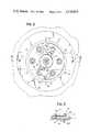
- FIG. 1is a side elevational view of the closed pumping system of the present invention with portions broken away for purposes of illustration.
- FIG. 2is an enlarged fragmentary sectional view taken as on line II--II of FIG. 1.
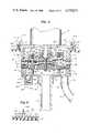
- FIG. 3is a fragmentary sectional view taken as on line III--III of FIG. 2.
- FIG. 4is a sectional view taken as on line IV--IV of FIG. 2.
- FIG. 5is a fragmentary sectional view taken as on line V--V of FIG. 4.
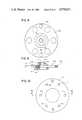
- FIG. 6is a side elevational view showing a portion of the detachable drive means of the present invention.
- FIG. 7is a sectional view taken as on the line VII--VII of FIG. 6.
- FIG. 8is a bottom view of that shown in FIG. 7 and taken as on line VIII--VIII of FIG. 6 with portions removed for purposes of clarity.
- FIG. 9is a side elevational view of a portion of that shown in FIG. 6 with portions thereof broken away for purposes of clarity.
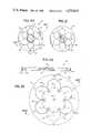
- FIG. 10is a top view of the sub-wobble plate.
- FIG. 11is a sectional view taken as on the line XI--XI of FIG. 10, and with a portion broken away for purposes of clarity.
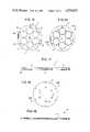
- FIG. 12is a top view of the upper section of the pump body of the present invention.
- FIG. 13is a bottom view of that shown in FIG. 12.
- FIG. 14is an enlarged sectional view taken as on the line XIV--XIV of FIG. 13.
- FIG. 15is a top view of the upper plate of the pump of the present invention.
- FIG. 16is a bottom view of that shown in FIG. 15.
- FIG. 17is an enlarged sectional view taken as on line XVII--XVII of FIG. 16.
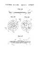
- FIG. 18is a top view of the diaphragm of the pump of the present invention.
- FIG. 19is an enlarged sectional view taken as on line XIX--XIX of FIG. 18.
- FIG. 20is a top view of the bottom plate of the pump of the present invention.
- FIG. 21is a bottom view of that shown in FIG. 20.
- FIG. 22is an enlarged sectional view taken as on the line XXII--XXII of FIG. 20.
- FIG. 23is a top view of a first gasket valve means of the present invention.
- FIG. 24is a sectional view taken as on line XXIV--XXIV of FIG. 23.
- FIG. 25is a top view of the lower plate of the pump of the present invention.
- FIG. 26is a bottom view of that shown in FIG. 25.
- FIG. 27is an enlarged sectional view taken as on the line XXVII--XXVII of FIG. 25.
- FIG. 28is a top view of the second gasket valve means of the present invention, with a broken line diagrammatic showing of the relationship of the valve holes to a valve flap.
- FIG. 29is a sectional view taken as on the line XXIX--XXIX of FIG. 28.
- FIG. 30is a top view of the lower section of the pump body of the present invention.
- FIG. 31is a bottom view of that shown in FIG. 30.
- FIG. 32is an enlarged sectional view taken as on the line XXXII--XXXII of FIG. 30.
- FIG. 33is an enlarged view of the piston means portion of that shown in FIG. 4.
- FIG. 34is a partly sectionalized view showing the operation of the pump means of the present invention.
- FIG. 35is a partly sectionalized view of the outlet means of the present invention.
- FIG. 36is an enlarged view of the lower end portion of the inlet pipe that is shown in FIG. 1.
- FIG. 37is a schematic view of the electrical system of the present invention.
- the pumping system 11 of the present inventionincludes, in general, a container 13 for holding the liquid chemicals L or the like, outlet means 15, dispensing means 17, pump means 19, drive means 21, and detachable means 23 for detachably coupling drive means 21 to the pump means 19.
- the container 13is enclosed by a wall 24 including cylindrical side wall 25, a bottom wall 26 integrally attached to the lower edge of cylindrical wall 25, and a top wall 27 integrally attached to the upper edge of cylindrical wall 23.
- Wall 24encloses and defines the interior 29 of the container 13 in which the liquid chemical L and the like is contained.
- the container 13is preferably formed of plastic or the like whereby it may be disposed of as by burning under certain EPA requirements.
- Top wall 27is provided with a first opening 31, preferably centrally thereof, and a second opening 33 spaced from opening 31.
- Pump means 19includes a pump body 35 preferably formed from a plastic that can be disposed of.
- Pump body 35is generally cylindrical and includes an upper section 37 and a lower section 39.
- An upper plate 41, an intermediate plate 43, and lower plate 45are sandwiched between upper section 37 and lower section 39.
- a flexible diaphragm 47is sandwiched between upper plate 41 and intermediate plate 43.
- a first gasket-valve 49is sandwiched between intermediate plate 43 and lower plate 45, and a second gasket-valve 51 is sandwiched between intermediate plate 43 and lower section 39.
- Lower section 39includes an annular bottom 57, an annular side wall 59 integrally formed at the outer edges of bottom 57 and upstanding therefrom, an annular inner wall 61 integrally formed with bottom 57 and upstanding therefrom at a place spaced inwardly from side wall 59 to establish with lower plate 45 an inlet chamber 63 inwardly of inner wall 61 and to establish a concentric outlet chamber 65 outwardly of inner wall 61.
- Lower section 39additionally includes a collar 67 integrally formed with bottom 57, depending centrally therefrom and establishing a socket 69 into which is fixedly mounted by suitable means an intake pipe 71 which is communicated with inlet chamber 63 at the upper end of pipe 71 and extends downwardly into the interior 29 of container 13 to a place adjacent but spaced from the bottom wall 26 to allow the liquid chemical L to flow into intake pipe 71 and into inlet chamber 63 when pump means 19 is operated, as will be better understood in the description to follow later in the specification.
- Lower section 39also includes an additional collar 73 integrally formed with bottom 57 and depending therefrom to establish a socket 75 which receives one end of a discharge pipe 77. The other end of pipe 77 remote from collar 73 is coupled to outlet means 15 (see FIG. 35).
- Upper plate 41(see FIGS. 15-17) includes a plurality of circular openings 79 therethrough, which preferably are spaced evenly around the plate and are preferably, though not necessarily, six in number, with the number depending upon the volume desired for the pump means 19. Centrally of the plate 41 is an opening 81 through which extends bolt means 83 for clampingly holding together central portions of plates 41, 43, 45, diaphragm 47 and first gasket-valve 49. A plurality of holes 85 are disposed around plate 41 to receive bolt means 55.
- Intermediate plate 43(see FIGS. 20-22) includes a plurality of circular openings 87 of a like number and size as circular openings 79 and are disposed in alignment therewith. Similarly, intermediate plate 43 has a plurality of holes 89 through which bolt means 55 passes. Centrally of plate 43 is a hole 91 through which bolt means 83 passes. In addition, centrally of intermediate plate 43 on the lower side thereof is provided an inverted dish shaped seat 93 for receiving the central portion of gasket-valve 49.
- Lower plate 45(see FIGS. 25-27) includes an inner group of inlet apertures 95 therethrough and an outer group of outlet apertures 97 therethrough. Apertures 95 are preferably grouped together in six groups of two each as best seen in FIGS. 25 and 26 with the groups being respectively in alignment with openings 79 and 87. In addition, holes 99 are provided around the periphery of plate 45 to receive the bolt means 55. A central hole 101 is provided through plate 45 to receive the bolt means 83. The central portion 103 of plate 45 is raised and dish shaped to correspond with seat 93 of plate 43 for clamping the central portion of the gasket-valve 49 between the seat 93 and the central portion 103 as best seen in FIG. 4. The lower surface of lower plate 45 protrudes downwardly as at 105 in dish shaped fashion to hold the gasket valve 51 against a correspondingly dish shaped upwardly facing seat 107 in lower section 39.
- Gasket valve 51(see FIGS. 28 and 29) has a plurality of cut out portions 109 to establish the plurality of arcuately shaped valve flaps 111 corresponding to the six groups of apertures 97.
- the valve flaps 111are positioned to underlie respectively the groups of apertures 97, as best seen in FIGS. 4 and 28.
- the valve flaps 111normally close the apertures 97 to prevent the flow upwardly through the apertures from outlet chamber 65 but permit flow downwardly through the apertures into outlet chamber 65.
- Gasket-valve 49(see FIGS. 23 and 24) includes a plurality of cut out portions 115 to provide a plurality of valve flaps 117 which normally respectively extend over apertures 95 to respectively block off the apertures 95 to prevent flow of the liquid chemical downwardly through the apertures but permit flow through apertures 95 from inlet chamber 63.
- the cut outs 115are arranged so that the gasket-valve 49 does not block the flow through the apertures 97.
- piston means 123there are a plurality of piston means 123 respectively provided to operate through the aligned circular openings 79, 87.
- piston means 123there are preferably six piston means 123 and the following description of one will suffice for all as they are substantially identical.
- Piston means 123includes a circular head portion 125, a centrally disposed stud portion 127 integrally formed with head portion 125 and upstanding therefrom. Stud 127 extends upwardly through one of a plurality of apertures 129, in diaphragm 47, with piston head 125 extending below diaphragm 47. Stud 127 is threaded on the exterior thereof as at 131. A washer 133 is mounted over stud 127 above diaphragm 47 and the portions of the diaphragm around the aperture 129 are clamped by means of a nut 135 above the washer 133 engaging threading 131 so that there is a fluid tight joint to prevent liquid flowing through aperture 129.
- a pump chamber 137is provided beneath each of the piston means 123 which extends downwardly to lower plate 45.
- the chamber 137is variable in size depending upon the position of the piston means 123. Thus, when a piston means 123 is in the upper position as shown by the one to the right in FIG. 4, the size or volume is at a maximum and when it is in a position shown to the left in FIG. 4, it is at a minimum.
- Each of the chambers 137is thus defined by portions of diaphragm 47, head portion 125, portions of intermediate plate 43 which define circular openings 87, and portions of lower plate 45.
- a bolt 139is threadedly engaged in a threaded socket 143 in the upper end of the stud 127.
- the head 145 of bolt 139is provided with a flange 147 fixed thereto, and an O-ring 149 is provided around the shaft of bolt 139 adjacent the flange 147.
- Each of piston means 123is loosely attached to a sub-wobble plate 151 with bolt 139 extending through one of a plurality of holes 153 in sub-wobble plate with O-ring 149 and flange 147 being above sub-wobble plate 151 and stud 127 being therebelow as best seen in FIG. 4.
- Upper section 37 of pump body 35is provided with a peripheral flange 155.
- Pump body 35is mounted in opening 31 of top wall 27 with the main portion of the pump body extending downwardly through the opening 31 and with flange 155 extending above portions of the top wall 27 adjacent opening 31, as best seen in FIG. 4.
- Flange 155is fixedly and sealably attached to top wall 27 by suitable well-known means, not shown, in a manner well-known to those skilled in the art.
- Threaded studs 157are fixedly attached to flange 155 by suitable means and upstand therefrom for purpose later to be described.
- Drive means 21includes actuating means 158 for actuating pump means 19 and includes motor means 159 for driving actuating means 158.
- Motor means 159is of any suitable construction such as an electric motor driven by a suitable power source as a battery 161.
- a suitable switch 162is provided for turning motor means off and on.
- Motor meansincludes a rotatable shaft 163.
- Actuating means 158includes a wobble plate means 165 mounted on shaft 163.
- Wobble plate means 165includes a hub 167 which has a cylindrical outer surface 169 which has its axis tilted relative to the axis of the central bore 171 of the hub 167.
- Hub 167is fixedly mounted on shaft 163 by suitable means and has an inner race 173 of ball bearing means 175 fixedly attached thereto.
- the outer race 177 of ball bearing means 175is fixedly attached to the plate per se 179 which is part of wobble plate means 165.
- Detachable means 181 for detachably coupling actuating means 158 to pump means 19includes catch means in the form of a pair of catches 183 having a head portion 185 and a threaded shank portion 187 attached thereto. Shank portion 187 is threadedly attached to sub-wobble plate 151 as by being threaded into threaded aperture 189. Catches 183 respectively extend through holes 184 provided in plate 179 with the head 185 extending above the plate 179 for engagement by a latch means 191 which is swingably mounted on a pivot screw 193.
- Each latch means 191has a notch 195 in the edge thereof so that the head portion 185 is engagable by latch means 191 with the shank portion 187 extending through the notch 195 to retain the wobble plate 179 in fixed engagement with sub-wobble plate 151 (see FIGS. 2 and 3).
- the latch means 191are swung away from catches 183 into the unlatched position shown in FIG. 7.
- Motor means 159is mounted on a cross member 197 by suitable means as screws 199.
- Cross member 197is removably mounted on pump body 35 by placing cross member 197 across flange 155 with studs 157 extending upwardly through apertures 201 in opposite ends of cross member 197. Then, wing nuts 203 are threadedly mounted on shank portions 157 to hold the cross member 197 in place.
- Dispensing means 17includes a suitable nozzle means 205 of well-known construction attached to the end of a hose 207 by suitable well-known means and at the other end the hose is attached to outlet means 15 by suitable means, which is preferably a quick disconnect means 209 of well-known construction actuated by the levers 211 to attach and detach the dispensing means 17 to the outlet means 15.
- the outlet means 15preferably includes a suitable male fitting 213 of a construction well-known to those skilled in the art which is adapted to mate with quick disconnect 209.
- Fitting 213is threadedly received in a collar 215 to which is fixedly attached the end of pipe 77 by suitable well-known means as a pipe section 217 screwed into the threaded interior of collar 15 and having ribs 216 to frictionally retain pipe 77.
- suitable well-known clampnot shown, if desired may be secured around pipe 77 to secure pipe 77 onto pipe section 217.
- Pump body 35is preferably provided with a dumping valve 219 which includes a ball 221 and spring 223 disposed in a short pipe section 225 extending from outlet chamber 65 to the interior of container 13.
- Spring 223normally holds ball 221 against seat 224 in a closed position.
- the lower end of pipe 71is preferably provided with a flexible skirt 227, which is held onto the lower end of pipe 71 by suitable means as a ring 229.
- the skirt 227is formed with accordianlike undulations 231 and extends below the lower end of pipe 71 into contact with bottom wall 26.
- a plurality of notches 233are provided in the lower edge of skirt 227 to permit the liquid chemicals to flow into pipe 71. It will be understood that the above-described construction of skirt 227 insures that the skirt is in contact with the bottom wall 26, even with variations in the depth of interior 29 of containers 13, so that substantially all of the liquid chemical can be dispensed from container 13.
- the user of the pumping system 11will probably own a drive means 21 and dispensing means 17 and will receive a container 13 which has the pump means 19 integrally attached thereto but without any drive means 21 or dispensing means 17.
- the usercan utilize his own drive means 21 and dispensing means 17 without having to buy the complete pumping system 11 each time he buys a container 13 full of liquid chemicals.
- the motor means 159is then turned on by closing the switch 162 which causes the wobble plate 179 to wobble and cause upward and downward movement of the piston means 123.
- This in turncauses the liquid chemical to be drawn up through the intake pipe 71 into the inlet chamber 63 due to the pumping action of the piston means 123.
- a piston means 123moves upwardly, it will cause a suction action to pull the liquid chemical through intake pipe 71, through apertures 95, whereupon it lifts valve flap 117 so that the liquid passes into chamber 137.
- This actionis shown in FIG. 34 where it will be seen that the piston means 123 to the left is in the beginning of its upward movement drawing liquid into chamber 137.
- the usermay then remove the drive means 21 and dispensing means 17. Then, the container 13 with the integral pump means 19 may be disposed of as by burning since all of the parts are plastic or otherwise disposable.
- system 11provides a closed system in that the opening 31 is at all times blocked off to prevent liquid chemicals from exiting therethrough.
- blocking meansis provided by diaphragm 47 to prevent contact of the chemicals by human hands during the entire operation of attaching and detaching drive means 21, dispensing of the liquid chemicals, disposing of the container 13, etc.
Landscapes
- Engineering & Computer Science (AREA)
- Mechanical Engineering (AREA)
- General Engineering & Computer Science (AREA)
- Reciprocating Pumps (AREA)
Abstract
Description
Claims (11)
Priority Applications (1)
| Application Number | Priority Date | Filing Date | Title |
|---|---|---|---|
| US06/526,906US4570833A (en) | 1983-08-26 | 1983-08-26 | Pumping system |
Applications Claiming Priority (1)
| Application Number | Priority Date | Filing Date | Title |
|---|---|---|---|
| US06/526,906US4570833A (en) | 1983-08-26 | 1983-08-26 | Pumping system |
Publications (1)
| Publication Number | Publication Date |
|---|---|
| US4570833Atrue US4570833A (en) | 1986-02-18 |
Family
ID=24099309
Family Applications (1)
| Application Number | Title | Priority Date | Filing Date |
|---|---|---|---|
| US06/526,906Expired - LifetimeUS4570833A (en) | 1983-08-26 | 1983-08-26 | Pumping system |
Country Status (1)
| Country | Link |
|---|---|
| US (1) | US4570833A (en) |
Cited By (28)
| Publication number | Priority date | Publication date | Assignee | Title |
|---|---|---|---|---|
| US4801249A (en)* | 1986-06-09 | 1989-01-31 | Ohken Seiko Co., Ltd. | Small-sized pump |
| US4804109A (en)* | 1987-12-14 | 1989-02-14 | Vanderjagt John A | Returnable container system |
| FR2672279A1 (en)* | 1991-02-05 | 1992-08-07 | Gruffy Georges | Apparatus for dispensing a liquid or pasty product and packaging (conditioning) of such a product for such an apparatus |
| US5150841A (en)* | 1989-09-11 | 1992-09-29 | Dowbrands Inc. | Liquid spray dispenser |
| US5199606A (en)* | 1991-08-22 | 1993-04-06 | The Mogul Corporation | Dispensing and measuring device having an internally extending outlet pipe and level sensor |
| US5305923A (en)* | 1990-06-06 | 1994-04-26 | The Coca-Cola Company | Postmix beverage dispensing system |
| US5366351A (en)* | 1993-07-29 | 1994-11-22 | Ingersoll-Dresser Pump Company | Pump with failure responsive discharge valve |
| US5435464A (en)* | 1994-05-17 | 1995-07-25 | Mobil Oil Corporation | System for the prevention of the jamming of pumps |
| US5494193A (en)* | 1990-06-06 | 1996-02-27 | The Coca-Cola Company | Postmix beverage dispensing system |
| US5494191A (en)* | 1994-05-02 | 1996-02-27 | Core Incorporated | Fluid containing and dispensing system |
| US5588811A (en)* | 1994-07-14 | 1996-12-31 | Price Manufacturing, Inc. | Air bed diaphragm pump |
| US6516976B2 (en) | 2000-12-19 | 2003-02-11 | Kimberly-Clark Worldwide, Inc. | Dosing pump for liquid dispensers |
| US6533145B2 (en) | 2000-12-19 | 2003-03-18 | Kimberly-Clark Worldwide, Inc. | Self-contained viscous liquid dispenser |
| US6540117B2 (en) | 2001-03-30 | 2003-04-01 | Kimberly-Clark Worldwide, Inc. | Dosing pump for liquid dispensers |
| US6981620B1 (en)* | 2004-05-06 | 2006-01-03 | Vicki Jo Buffin | Easer icer |
| US20070031268A1 (en)* | 2001-08-14 | 2007-02-08 | Carmeli Adahan | Compact vacuum pump |
| EP1840045A1 (en) | 2006-03-29 | 2007-10-03 | Flowserve Management Company | Low profile pump and lid assembly for a stackable container |
| JP2011069369A (en)* | 2009-09-24 | 2011-04-07 | Itt Manufacturing Enterprises Inc | Disposable pump head |
| US20130270303A1 (en)* | 2010-10-08 | 2013-10-17 | Charles A. Centofante | Dispensing liquids from a container coupled to an integrated pump cap |
| WO2016026373A1 (en)* | 2014-08-22 | 2016-02-25 | 柳践 | Power-driven fuel-adding oil tank cover and oil delivery method thereof |
| US20170043994A1 (en)* | 2015-08-13 | 2017-02-16 | David G. Kraenzle | Apparatus, systems, and methods relating to transfer of fluids to/from containers and/or storage/transport of fluids in containers |
| USD898868S1 (en) | 2018-09-12 | 2020-10-13 | 3M Innovative Properties Company | Liquid delivery system lid |
| US10974954B2 (en)* | 2017-04-18 | 2021-04-13 | Scheugenpflug Ag | Emptying device for viscous materials and method for same |
| USD918339S1 (en) | 2018-09-12 | 2021-05-04 | 3M Innovative Properties Company | Liquid delivery system cup |
| USD919045S1 (en) | 2018-09-12 | 2021-05-11 | 3M Innovative Properties Company | Liquid delivery system coupler |
| US11027960B2 (en) | 2015-08-13 | 2021-06-08 | David G. Kraenzle | Apparatus, systems, and methods relating to transfer of liquids to/from containers and/or storage of liquids in containers |
| US20210355934A1 (en)* | 2018-10-11 | 2021-11-18 | Psg Germany Gmbh | Diaphragm pump |
| US11466689B1 (en)* | 2022-06-01 | 2022-10-11 | Zhongshan Peili Technology Co., Ltd. | Fuel pump |
Citations (4)
| Publication number | Priority date | Publication date | Assignee | Title |
|---|---|---|---|---|
| US3055304A (en)* | 1959-02-11 | 1962-09-25 | Gen Motors Corp | Pump and control system therefor |
| US3227326A (en)* | 1962-10-09 | 1966-01-04 | Carl F Beamer | Material-handling apparatus |
| US4245760A (en)* | 1978-05-08 | 1981-01-20 | Terminator Products, Inc. | Container with built-in probe assembly and coupling head assembly therefor |
| US4396357A (en)* | 1981-04-06 | 1983-08-02 | Product Research And Development | Diaphragm pump with ball bearing drive |
- 1983
- 1983-08-26USUS06/526,906patent/US4570833A/ennot_activeExpired - Lifetime
Patent Citations (4)
| Publication number | Priority date | Publication date | Assignee | Title |
|---|---|---|---|---|
| US3055304A (en)* | 1959-02-11 | 1962-09-25 | Gen Motors Corp | Pump and control system therefor |
| US3227326A (en)* | 1962-10-09 | 1966-01-04 | Carl F Beamer | Material-handling apparatus |
| US4245760A (en)* | 1978-05-08 | 1981-01-20 | Terminator Products, Inc. | Container with built-in probe assembly and coupling head assembly therefor |
| US4396357A (en)* | 1981-04-06 | 1983-08-02 | Product Research And Development | Diaphragm pump with ball bearing drive |
Cited By (43)
| Publication number | Priority date | Publication date | Assignee | Title |
|---|---|---|---|---|
| US4801249A (en)* | 1986-06-09 | 1989-01-31 | Ohken Seiko Co., Ltd. | Small-sized pump |
| US4804109A (en)* | 1987-12-14 | 1989-02-14 | Vanderjagt John A | Returnable container system |
| US5150841A (en)* | 1989-09-11 | 1992-09-29 | Dowbrands Inc. | Liquid spray dispenser |
| US5305923A (en)* | 1990-06-06 | 1994-04-26 | The Coca-Cola Company | Postmix beverage dispensing system |
| US5494193A (en)* | 1990-06-06 | 1996-02-27 | The Coca-Cola Company | Postmix beverage dispensing system |
| FR2672279A1 (en)* | 1991-02-05 | 1992-08-07 | Gruffy Georges | Apparatus for dispensing a liquid or pasty product and packaging (conditioning) of such a product for such an apparatus |
| US5199606A (en)* | 1991-08-22 | 1993-04-06 | The Mogul Corporation | Dispensing and measuring device having an internally extending outlet pipe and level sensor |
| US5366351A (en)* | 1993-07-29 | 1994-11-22 | Ingersoll-Dresser Pump Company | Pump with failure responsive discharge valve |
| US5450987A (en)* | 1993-07-29 | 1995-09-19 | Ingersoll-Dresser Pump Company | Pumping system with failure responsive discharge valve |
| US5494191A (en)* | 1994-05-02 | 1996-02-27 | Core Incorporated | Fluid containing and dispensing system |
| US5435464A (en)* | 1994-05-17 | 1995-07-25 | Mobil Oil Corporation | System for the prevention of the jamming of pumps |
| US5588811A (en)* | 1994-07-14 | 1996-12-31 | Price Manufacturing, Inc. | Air bed diaphragm pump |
| US6516976B2 (en) | 2000-12-19 | 2003-02-11 | Kimberly-Clark Worldwide, Inc. | Dosing pump for liquid dispensers |
| US6729502B2 (en) | 2000-12-19 | 2004-05-04 | Kimberly-Clark Worldwide, Inc. | Self-contained viscous liquid dispenser |
| US6533145B2 (en) | 2000-12-19 | 2003-03-18 | Kimberly-Clark Worldwide, Inc. | Self-contained viscous liquid dispenser |
| US6543651B2 (en) | 2000-12-19 | 2003-04-08 | Kimberly-Clark Worldwide, Inc. | Self-contained viscous liquid dispenser |
| US6575334B2 (en) | 2000-12-19 | 2003-06-10 | Kimberly-Clark Worldwide, Inc. | Self-contained viscous liquid dispenser |
| US6575335B2 (en) | 2000-12-19 | 2003-06-10 | Kimberly-Clark Worldwide, Inc. | Self-contained viscous liquid dispenser |
| US6648179B2 (en) | 2000-12-19 | 2003-11-18 | Kimberly-Clark Worldwide, Inc. | Self-contained viscous liquid dispenser |
| US6540117B2 (en) | 2001-03-30 | 2003-04-01 | Kimberly-Clark Worldwide, Inc. | Dosing pump for liquid dispensers |
| US7758539B2 (en)* | 2001-08-14 | 2010-07-20 | Carmeli Adahan | Compact vacuum pump |
| US20070031268A1 (en)* | 2001-08-14 | 2007-02-08 | Carmeli Adahan | Compact vacuum pump |
| US20070166180A1 (en)* | 2001-08-14 | 2007-07-19 | Carmeli Adahan | Compact vacuum pump |
| US7918654B2 (en) | 2001-08-14 | 2011-04-05 | Carmeli Adahan | Compact vacuum pump |
| US20070269321A1 (en)* | 2001-08-14 | 2007-11-22 | Carmeli Adahan | Compact vacuum pump |
| US20070297924A1 (en)* | 2001-08-14 | 2007-12-27 | Carmeli Adahan | Compact vacuum pump |
| US20080056915A1 (en)* | 2001-08-14 | 2008-03-06 | Carmeli Adahan | Compact vacuum pump |
| US6981620B1 (en)* | 2004-05-06 | 2006-01-03 | Vicki Jo Buffin | Easer icer |
| EP1840045A1 (en) | 2006-03-29 | 2007-10-03 | Flowserve Management Company | Low profile pump and lid assembly for a stackable container |
| JP2011069369A (en)* | 2009-09-24 | 2011-04-07 | Itt Manufacturing Enterprises Inc | Disposable pump head |
| US20130270303A1 (en)* | 2010-10-08 | 2013-10-17 | Charles A. Centofante | Dispensing liquids from a container coupled to an integrated pump cap |
| WO2016026373A1 (en)* | 2014-08-22 | 2016-02-25 | 柳践 | Power-driven fuel-adding oil tank cover and oil delivery method thereof |
| US11027960B2 (en) | 2015-08-13 | 2021-06-08 | David G. Kraenzle | Apparatus, systems, and methods relating to transfer of liquids to/from containers and/or storage of liquids in containers |
| US20170043994A1 (en)* | 2015-08-13 | 2017-02-16 | David G. Kraenzle | Apparatus, systems, and methods relating to transfer of fluids to/from containers and/or storage/transport of fluids in containers |
| US10005654B2 (en)* | 2015-08-13 | 2018-06-26 | David G. Kraenzle | Apparatus, systems, and methods relating to transfer of fluids to/from containers and/or storage/transport of fluids in containers |
| US10974954B2 (en)* | 2017-04-18 | 2021-04-13 | Scheugenpflug Ag | Emptying device for viscous materials and method for same |
| USD898868S1 (en) | 2018-09-12 | 2020-10-13 | 3M Innovative Properties Company | Liquid delivery system lid |
| USD919045S1 (en) | 2018-09-12 | 2021-05-11 | 3M Innovative Properties Company | Liquid delivery system coupler |
| USD918339S1 (en) | 2018-09-12 | 2021-05-04 | 3M Innovative Properties Company | Liquid delivery system cup |
| US20210355934A1 (en)* | 2018-10-11 | 2021-11-18 | Psg Germany Gmbh | Diaphragm pump |
| US12116994B2 (en)* | 2018-10-11 | 2024-10-15 | Psg Germany Gmbh | Diaphragm pump |
| US11466689B1 (en)* | 2022-06-01 | 2022-10-11 | Zhongshan Peili Technology Co., Ltd. | Fuel pump |
| EP4286679A1 (en)* | 2022-06-01 | 2023-12-06 | Zhongshan Peili Technology Co., Ltd. | Modular fuel transfer pump flow passage structure and fuel transfer pump |
Similar Documents
| Publication | Publication Date | Title |
|---|---|---|
| US4570833A (en) | Pumping system | |
| US3746171A (en) | Filter assembly | |
| JP4570830B2 (en) | Reusable filter cartridge and pressure vessel | |
| US5376271A (en) | Liquid filtration unit | |
| US5474674A (en) | External filtration device particularly for aquariums and ornamental water tanks | |
| EP0489829B1 (en) | A valve arrangement | |
| US5258118A (en) | Reusable fluid filter | |
| JPS61283314A (en) | Filter apparatus | |
| US4253959A (en) | Liquid filter vessel | |
| US2731297A (en) | Hydraulically operated liquid sprayer | |
| US5151179A (en) | Faucet connected water filter | |
| US3470826A (en) | Jet pump and valve combination | |
| BRPI0505108B1 (en) | liquid filter in particular for the lubricating oil of an internal combustion machine and filter element for a liquid filter | |
| JPH02245206A (en) | Liquid filter | |
| US10059603B2 (en) | Water filtration apparatus with compostable filter | |
| US7585408B2 (en) | Liquid filter | |
| US4614481A (en) | Pump with replaceable cartridge | |
| US3199745A (en) | Portable pump assembly | |
| US20080168597A1 (en) | Portable Toilet | |
| US6644515B1 (en) | Filter-valve assembly | |
| US3206031A (en) | Liquid dispenser for the purification and filtration of water | |
| US5497813A (en) | Apparatus for opening sealed containers | |
| JPH06327909A (en) | Liquid capsule type filter device | |
| US4557669A (en) | Pumping apparatus | |
| JPH0688365A (en) | Joint for pressure type water washing stool |
Legal Events
| Date | Code | Title | Description |
|---|---|---|---|
| STCF | Information on status: patent grant | Free format text:PATENTED CASE | |
| REMI | Maintenance fee reminder mailed | ||
| FPAY | Fee payment | Year of fee payment:4 | |
| SULP | Surcharge for late payment | ||
| AS | Assignment | Owner name:INGERSOLL-RAND COMPANY, NEW JERSEY Free format text:ASSIGNMENT OF ASSIGNORS INTEREST.;ASSIGNOR:VANDERJAGT, JOHN A.;REEL/FRAME:005304/0038 Effective date:19900314 Owner name:INGERSOLL-RAND COMPANY, NEW JERSEY Free format text:ASSIGNMENT OF ASSIGNORS INTEREST.;ASSIGNOR:VANDERJAGT, JOHN A.;REEL/FRAME:005304/0043 Effective date:19900314 | |
| FEPP | Fee payment procedure | Free format text:PAYOR NUMBER ASSIGNED (ORIGINAL EVENT CODE: ASPN); ENTITY STATUS OF PATENT OWNER: LARGE ENTITY | |
| FEPP | Fee payment procedure | Free format text:PAT HLDR NO LONGER CLAIMS SMALL ENT STAT AS INDIV INVENTOR (ORIGINAL EVENT CODE: LSM1); ENTITY STATUS OF PATENT OWNER: LARGE ENTITY | |
| AS | Assignment | Owner name:INGERSOLL-DRESSER PUMP COMPANY, NEW JERSEY Free format text:CORRECTIVE ASSIGNMENT TO CORRECT ERRONEOUS PATENT NUMBER ASSIGNMENT PREVIOUSLY RECORDED AS REEL 6308 FRAMES 008;ASSIGNOR:INGERSOLL-RAND COMPANY;REEL/FRAME:006479/0898 Effective date:19920925 | |
| FPAY | Fee payment | Year of fee payment:8 | |
| FPAY | Fee payment | Year of fee payment:12 | |
| AS | Assignment | Owner name:BANK OF AMERICA, N.A., AS COLLATERAL AGENT, CALIFO Free format text:SECURITY AGREEMENT;ASSIGNOR:FLOWSERVE MANAGEMENT COMPANY;REEL/FRAME:011035/0494 Effective date:20000808 | |
| AS | Assignment | Owner name:FLOWSERVE MANAGEMENT COMPANY, TEXAS Free format text:ASSIGNMENT OF ASSIGNORS INTEREST;ASSIGNOR:INGERSOLL-DRESSER PUMP COMPANY;REEL/FRAME:011806/0040 Effective date:20010517 |