US4569674A - Continuous vacuum wound drainage system - Google Patents
Continuous vacuum wound drainage systemDownload PDFInfo
- Publication number
- US4569674A US4569674AUS06/404,791US40479182AUS4569674AUS 4569674 AUS4569674 AUS 4569674AUS 40479182 AUS40479182 AUS 40479182AUS 4569674 AUS4569674 AUS 4569674A
- Authority
- US
- United States
- Prior art keywords
- reservoir
- vacuum
- housing
- base unit
- bottle
- Prior art date
- Legal status (The legal status is an assumption and is not a legal conclusion. Google has not performed a legal analysis and makes no representation as to the accuracy of the status listed.)
- Expired - Lifetime
Links
- 206010052428WoundDiseases0.000claimsdescription70
- 208000027418Wounds and injuryDiseases0.000claimsdescription70
- 239000007788liquidSubstances0.000claimsdescription24
- 238000003780insertionMethods0.000claimsdescription12
- 230000037431insertionEffects0.000claimsdescription12
- 230000002209hydrophobic effectEffects0.000claimsdescription11
- 244000273618Sphenoclea zeylanicaSpecies0.000claimsdescription6
- 239000012528membraneSubstances0.000claimsdescription6
- 239000012530fluidSubstances0.000claimsdescription5
- 238000012544monitoring processMethods0.000claimsdescription4
- 230000000694effectsEffects0.000claimsdescription3
- 239000004816latexSubstances0.000claimsdescription3
- 229920000126latexPolymers0.000claimsdescription3
- 238000007789sealingMethods0.000claimsdescription3
- 238000012546transferMethods0.000claimsdescription2
- 239000007789gasSubstances0.000claims2
- 238000004891communicationMethods0.000claims1
- 238000007373indentationMethods0.000claims1
- 239000003990capacitorSubstances0.000description9
- 238000010586diagramMethods0.000description4
- 239000004020conductorSubstances0.000description3
- 238000000465mouldingMethods0.000description3
- 230000009977dual effectEffects0.000description2
- 239000000463materialSubstances0.000description2
- 238000012986modificationMethods0.000description2
- 230000004048modificationEffects0.000description2
- 210000003205muscleAnatomy0.000description2
- 238000011084recoveryMethods0.000description2
- 238000010992refluxMethods0.000description2
- 238000001356surgical procedureMethods0.000description2
- 210000001519tissueAnatomy0.000description2
- 235000014676Phragmites communisNutrition0.000description1
- 239000000853adhesiveSubstances0.000description1
- 238000004026adhesive bondingMethods0.000description1
- 230000001070adhesive effectEffects0.000description1
- 230000000903blocking effectEffects0.000description1
- OJIJEKBXJYRIBZ-UHFFFAOYSA-Ncadmium nickelChemical group[Ni].[Cd]OJIJEKBXJYRIBZ-UHFFFAOYSA-N0.000description1
- 238000004140cleaningMethods0.000description1
- 230000000295complement effectEffects0.000description1
- 238000011109contaminationMethods0.000description1
- 238000000151depositionMethods0.000description1
- 238000006073displacement reactionMethods0.000description1
- 238000007667floatingMethods0.000description1
- 230000009969flowable effectEffects0.000description1
- 230000035876healingEffects0.000description1
- 238000009434installationMethods0.000description1
- 238000002372labellingMethods0.000description1
- 239000011344liquid materialSubstances0.000description1
- 238000004519manufacturing processMethods0.000description1
- 239000002991molded plasticSubstances0.000description1
- 230000000474nursing effectEffects0.000description1
- 230000003287optical effectEffects0.000description1
- 230000010355oscillationEffects0.000description1
- 239000004033plasticSubstances0.000description1
- 229920003023plasticPolymers0.000description1
- 239000002985plastic filmSubstances0.000description1
- 229920006255plastic filmPolymers0.000description1
- 239000002984plastic foamSubstances0.000description1
- 239000011148porous materialSubstances0.000description1
- 230000008707rearrangementEffects0.000description1
- 238000012360testing methodMethods0.000description1
- 230000000007visual effectEffects0.000description1
- 239000002699waste materialSubstances0.000description1
Images


Classifications
- A—HUMAN NECESSITIES
- A61—MEDICAL OR VETERINARY SCIENCE; HYGIENE
- A61M—DEVICES FOR INTRODUCING MEDIA INTO, OR ONTO, THE BODY; DEVICES FOR TRANSDUCING BODY MEDIA OR FOR TAKING MEDIA FROM THE BODY; DEVICES FOR PRODUCING OR ENDING SLEEP OR STUPOR
- A61M27/00—Drainage appliance for wounds or the like, i.e. wound drains, implanted drains
- A—HUMAN NECESSITIES
- A61—MEDICAL OR VETERINARY SCIENCE; HYGIENE
- A61M—DEVICES FOR INTRODUCING MEDIA INTO, OR ONTO, THE BODY; DEVICES FOR TRANSDUCING BODY MEDIA OR FOR TAKING MEDIA FROM THE BODY; DEVICES FOR PRODUCING OR ENDING SLEEP OR STUPOR
- A61M1/00—Suction or pumping devices for medical purposes; Devices for carrying-off, for treatment of, or for carrying-over, body-liquids; Drainage systems
- A61M1/80—Suction pumps
- A61M1/802—Suction pumps by vacuum created above a liquid flowing from a closed container
- A—HUMAN NECESSITIES
- A61—MEDICAL OR VETERINARY SCIENCE; HYGIENE
- A61M—DEVICES FOR INTRODUCING MEDIA INTO, OR ONTO, THE BODY; DEVICES FOR TRANSDUCING BODY MEDIA OR FOR TAKING MEDIA FROM THE BODY; DEVICES FOR PRODUCING OR ENDING SLEEP OR STUPOR
- A61M1/00—Suction or pumping devices for medical purposes; Devices for carrying-off, for treatment of, or for carrying-over, body-liquids; Drainage systems
- A61M1/60—Containers for suction drainage, adapted to be used with an external suction source
- A—HUMAN NECESSITIES
- A61—MEDICAL OR VETERINARY SCIENCE; HYGIENE
- A61M—DEVICES FOR INTRODUCING MEDIA INTO, OR ONTO, THE BODY; DEVICES FOR TRANSDUCING BODY MEDIA OR FOR TAKING MEDIA FROM THE BODY; DEVICES FOR PRODUCING OR ENDING SLEEP OR STUPOR
- A61M2205/00—General characteristics of the apparatus
- A61M2205/82—Internal energy supply devices
- A61M2205/8206—Internal energy supply devices battery-operated
Definitions
- This inventionrelates to a vacuum drainage system for wounds, and more particularly to such system having a reservoir connectible to the wound for receiving drainage fluid therefrom and apparatus for applying a negative pressure to the reservoir.
- the drainage containeris provided with a wall or walls manually deflectable inward for reducing the effective volume within the container and resilient means for oppositely deflecting such wall or walls to expand the internal volume of the container and thereby establish a negative pressure therein for drawing liquid from the wound.
- these unitshave been made compact and light weight enough to be secured to and carried by an ambulatory patient, for example after surgery to continue drainage of the healing wound.
- Lloyd U.S. Pat. No. 3,572,340One example is disclosed by Lloyd U.S. Pat. No. 3,572,340.
- such devicestypically do not provide precise control of maximum negative pressure since the degree of inward deflection may vary widely among different users or may not be clearly or reliably related to developed maximum negative pressure.
- prior drainage devices of another kindmay more closely maintain negative pressure within a drain container in a relatively narrow negative pressure range and may be capable of continuous operation over a relatively long time without need to deform the container or otherwise manually reactivate the negative pressure source.
- One exampleis shown in Crowley U.S. Pat. No. 3,675,653.
- systems of this kindhave generally been relatively bulky and hence have confined the patient to close proximity to a stationary vacuum pump and control.
- a continuous vacuum drainage system for wound drainageincluding a drain reservoir, a base unit having means responsive to releasable attachment thereto of such a drain reservoir for evacuating such reservoir to a subatmospheric pressure in a predetermined range, and wherein the drain reservoir has means continuously operable before, during and after release from the base unit for uninterrupted suction draining of a wound.
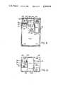
- FIG. 1is a front view of a continuous vacuum wound drainage system embodying the invention, with the reservoir installed in a position of use on the base unit.
- FIG. 2is a partially broken side view of the apparatus of FIG. 1.
- FIG. 3is a bottom view of the apparatus of FIG. 2.
- FIG. 3Ais a fragmentary sectional view substantially as taken on the line IIIA--IIIA of FIG. 8 hereafter described.
- FIG. 4is a top view of the reservoir of FIG. 1.
- FIG. 5is a diagrammatic cross-sectional view substantially taken on the line V--V of FIG. 1.
- FIG. 6is a fragmentary side view of the upper forward portion of the reservoir substantially taken on the line VI--VI of FIG. 1.
- FIG. 7is a fragmentary sectional view of the vacuum connection assembly substantially as taken on the line VII--VII of FIG. 4.
- FIG. 7Adiscloses a modification of the vacuum connection assembly boss portion of the receptacle of FIG. 7.
- FIG. 8is a central cross-sectional view substantially as taken on line VIII--VIII of FIG. 1.
- FIG. 9is a partially broken sectional view substantially taken on the line IX--IX of FIG. 8.
- FIG. 10is a partially broken top view substantially taken on the line X--X of FIG. 2.
- FIG. 11is a block diagram of the control circuitry of the system of FIG. 1.
- FIG. 11Ais a block diagram of the power supply portion of the control circuitry for applying DC operating potential to the FIG. 11 apparatus.
- FIG. 12is a circuit diagram corresponding in content to the block diagram of FIG. 11 and disclosing the control circuitry in more detail.
- FIGS. 1 and 2disclose a continuous vacuum drainage system 10 for draining of a closed wound.
- the system 10includes a portable drain reservoir 13 and a base unit 12 to which the reservoir is releasably securable for partial evacuation to a subatmospheric (negative) pressure.
- a wound drain tube 22is used to connect the reservoir 13 to a wound W to be drained.
- the reservoir 13is disconnectible from the base unit 12 without such disconnection impairing the negative pressure within the reservoir.
- the reservoir 13can be used for vacuum wound drainage both while connected with the base unit 12 as shown in FIGS. 1 and 2 as well as after disconnection from the base unit, thus permitting the reservoir to be carried by the patient or on a mobile patient support (not shown) to locations remote from the base unit 12.
- the base unit 12comprises a housing 201 (FIGS. 1, 2 and 3) which in the preferred embodiment housing 201 has a forwardly and downwardly facing recess 202 (FIGS. 2 and 3) into which the reservoir 13 is insertable.
- the housing 201is conveniently rectilinear, except for the recess 202, and comprises front and back walls 203 and 204, top and bottom walls 206 and 207 and side walls 208.
- the recess 202has forward and downward facing walls 210 and 211.
- the top and rear walls 206 and 204conveniently together form a cover 213 (FIGS. 2 and 8) removable from the remainder of the housing to allow access to the interior. Cover 213 is releasably fixed to the remainder of the housing 201 by any conventional means, such as screws, not shown.
- Housing 201is preferably of a molded plastics material.
- An attachment bracket 214(FIG. 2) is fixed to the housing 201, as by screws 215 for removably supporting the housing on a support indicated in broken lines at 216, for example a fixed support in a hospital or operating room, or a rail or other part on a semi-mobile or mobile patient carrier, such as a hospital bed, gurney, or wheelchair.
- Bracket 214preferably comprises a pair of downwardly opening hooks 217 spaced at opposite ends of and extending upward from a mounting plate 218 secured by the screws 215 to the upper edge of housing back 204 to pendantly support the housing 201.
- the drain reservoir 13comprises a hollow bottle 220 (FIGS. 1, 4 and 8) having a back wall 221 complimentary to the forwardly facing recess wall 210 and hence flat in the embodiment shown.
- the bottle 220is conveniently approximately rectilinear and is received in the housing recess 202 with its front wall 222 spaced forwardly from the front wall 203 of the housing, as seen in FIG. 2, to provide room for the wound drain tube 22 and means (hereinafter described) connecting same to the bottle.
- the reservoir 13may be manufactured in any convenient manner.
- the bottle 220may be assembled from a separate top 223 fixedly sealed to a cup-shaped bottom 224, as by the overlapped joint 226 (indicated only at the left in FIG. 7 but extending circumferentially around the top 223 and bottom 224) fixedly as by adhesive or heat.
- Insertion of the reservoir 13 into the recess 202 of housing 12interengages the two by means of a vacuum connection assembly 229 (FIG. 7) through which the base unit provides the reservoir with a negative pressure, and by means of mounting structure for supporting the reservoir on the housing.
- a vacuum connection assembly 229FIG. 7
- Such mounting structureincludes a single motion guide assembly 231 (FIGS. 3A and 8) for guiding the reservoir properly into position on the housing, and a latch assembly 233 (FIGS. 1 and 5) for releasably fixing the reservoir in supported relation on said housing.
- the vacuum connection assembly 229, guide assembly 231 and latch assembly 233are all arranged for straight line upward insertion of the reservoir 13 into the recess 202 of the base unit 12.
- the vacuum connection assembly 229(FIG. 7) includes a hollow cylindrical boss 236 extending upward from the right (FIGS. 1 and 4) rear corner portion of the bottle top 223.
- a pocket 237(FIGS. 3 and 7) opens downward through the downward facing wall 211 of the housing into recess 202 and has taper-ended vertical guide ribs 238 fixed therein to snugly guide the upper end of the boss 236 of the bottle upward against, or substantially against, the upper end 239 of the pocket 237, and such that the top 223 of the bottle lies just beneath the overhanging, downwardly facing wall 211 of the housing.
- the pocket upper end 239here defines a shelf which, conveniently, is formed as part of a shelf assembly 241 (FIGS. 9 and 10) preferably molded integrally with the front wall 203 of the housing 201, as seen in FIGS. 9 and 10.
- a commercially available, disklike, hydrophobic filter unit 243rests atop the shelf 239 and has an upwardly protruding hollow stem 244 connected through a vacuum hose 246 to a motor driven vacuum pump unit 247 (FIGS. 9 and 10) preferably fixed on a further portion of the shelf assembly 241 within the housing.
- the filter unit 243is releasably held on the shelf 239 by any convenient means, here by a pair of legs 248 fixedly depending from the removable housing top wall.
- the filter unit 243also has a depending hollow stem 245 (FIG. 7). Stem 245 extends downward through an opening in the housing shelf 239 and thence sealingly through an annular resilient membrane 251 (here of latex or the like) held in the stepped upper end of the boss 236 by a conventional resilient friction ring 252 to seal the vacuum connection from the interior of the hollow boss 236, through the filter unit 243 to the vacuum pump 247.
- annular resilient membrane 251here of latex or the like
- a one-way valve 254 in the hollow boss 236 beneath stem 245 in the preferred embodiment shownis of the commercially available reflux, or "duck-bill" type.
- the one-way valve 254is oriented for evacuation of gas upward from the reservoir by the vacuum pump unit 247 but closes upon shutting off or disconnection of the vacuum pump for preventing backflow of air or the like therethrough into the bottle 220.
- a conventional duck-bill valve 254has an upstanding tubular central portion, opposite sides of which are pre-biased to flatten and converge toward the top of the valve to form a slit normally resiliently closed to block downward flow therethrough but resiliently openable to allow upward flow therethrough.
- a perforated retainer 256is fixed, as by adhesive bonding, beneath the top 223 of the bottle to retain the valve 254, normally to allow upward gas flow from the bottle interior through the valve 254 to the vacuum pump, and also to provide a downward facing seat 257.
- a float valve 259comprises a floating body (for example of closed pore, rigid plastic foam) hinged by a flexible leaf 260 of plastic film on the underside of the bottle top 223, to lift up and seal against the perforated retainer 256 and prevent overflow should liquid in the bottle rise to near the top.
- the guide assembly 231(FIGS. 3A and 8) comprises an undercut slot 263 formed, as by molding, in the forwardly facing wall 210 of the housing recess 202.
- the slot 263is preferably centrally located on the forwardly facing wall 210 and extends vertically from top to bottom thereof.
- a T-cross-section railis fixed, preferably by molding, to the back wall 221 of the bottle 220 as seen in FIG. 4, and is snugly but upwardly slidably receivable in the undercut slot 263 of the housing to guide the bottle 220 upward into the housing recess 202 and guide the boss 236 upward into the pocket 237.
- the T-rail 265preferably extends vertically substantially the full height of the bottle 220 and is preferably centered laterally on the back wall 221 thereof.
- the T-rail 265 and the surfaces defining the undercut slot 263may be chamfered at their respective upper and lower ends to facilitate entry of the top of the T-rail into the bottom of the undercut slot.
- a power switch unit 116(FIG. 3A) here comprises individual on-off switches 116A and 116B actuable to a conductive state by insertion of the reservoir 13 into the base unit 12.
- switches 116A and 116Bare fixed on the interior side of the forwardly facing recess wall 210 near the top thereof and have respective actuators 267A and 267B extending through openings in the housing wall into the undercut slot 263 for displacement by the top of the T-rail 265 during the last of its rise along the undercut slot 263.
- Suitable seal meansmay be provided where the mechanical switch actuators 267A and 267B protrude through the housing wall into the undercut slot 263.
- switches of other typesmay be used, for example, proximity switches, such as magnetically operated reed switches actuated by magnetized means on the T-rail 265, or optical or other nonmechanically operated switches.
- proximity switchessuch as magnetically operated reed switches actuated by magnetized means on the T-rail 265, or optical or other nonmechanically operated switches.
- Use of a nonmechanically operated switch at 116A and 116Beliminates the need for any perforation through the wall of the housing and hence any need for a seal thereat.
- the latch assembly 233(FIGS. 1, 3 and 5) includes a manually releasable snap-type structure pendantly supporting the bottle 220 snugly beneath the downward facing wall 211 of the housing recess 202.
- the latch assembly 233here includes an upstanding deflectable member 271 generally of L-shaped cross section as seen in elevation in FIG. 5.
- the member 271has a resiliently rearwardly deflectable first leg 272 upstanding from and fixed (preferably by integral molding therewith) to the top 223 of bottle 220.
- the deflectable leg 272is thin from front to rear as seen in FIG. 5 and substantially wider from side to side as seen in FIG. 1, to permit rearward deflection of the top of the member 271 rearwardly.
- the top leg 273extends forwardly from the top of deflectable leg 272 and is considerably taller and wider than its front-to-rear thickness.
- the deflectable member 271is spaced along the top of the bottle from both the boss 236 and the axis of drain tube 22 as seen in FIG. 4.
- An opening 275opens through the downward facing wall 211 of the housing 201 near the housing front wall 203.
- the top portion of the opening 275opens forwardly through the housing front wall 203 to form a finger access port 276.
- the bottom of port 276is closed by a transversely extending portion of the housing front wall, namely a ledge 277 on the flat top of which the forward facing top leg 273 of the member 271 rests to latch the bottle 220 in pendantly supported relation on the housing 201. Inserting a human finger through the port 276 shifts top leg 273 rearwardly in the opening 275 and off the ledge 277, thereby unlatching the bottle 220 and allowing it to drop from the housing 221.
- portions of the reservoir 13 engaged by liquid drained from wound Wsame include a wound drain port 280 (FIGS. 1 and 8) at which the wound drain tube 22 is releasably connectible to the top of the bottle 220, and a bottle emptying port 281 at the bottom of the bottle for emptying of liquid collected from the wound.
- a wound drain port 280FIGS. 1 and 8
- a bottle emptying port 281at the bottom of the bottle for emptying of liquid collected from the wound.
- the wound drain port 280comprises an internally and externally stepped hollow boss 282 (FIG. 8) fixed, and preferably integrally molded, in upstanding relation on the front portion of the top 223 of bottle 220, ahead of the front wall 203 of the housing 201.
- the wound drainage tube 22terminates in a sleeve 283 for removable telescoping over the upstanding boss 282 on the bottle.
- the sleeve 282, near its upper end,has an annular groove for receiving an O-ring seal, or the like, at 285 for sealing against leakage of liquid from the wound between the sleeve and boss.
- the one-way valve 286permits in-flow of liquid from the wound through tube 22 and the central through-bore of hollow boss 282, but precludes reverse flow from the interior of bottle 220, to preclude contamination of the wound.
- a releasable latch 289is provided.
- the latch 289here is of bayonet type and comprises a pin 290 protruding radially from the boss 282 for entering an L-shaped slot 291 at the bottom of sleeve 283 (FIG. 2).
- Latchingis accomplished by downward movement of the tube 22 and sleeve 283 to enter the pin 290 in the vertical lower leg of the slot 291, whereafter rotation of the sleeve 283 and tube 22 locates the pin 290 at the blind end of the horizontal leg of the L-shaped slot 291 to axially fix the sleeve 283 and tube 22 to the bottle.
- the tube 22 and sleeve 283are releasable from the bottle by reversal of the rotation and axial latching movements above described.
- the emptying port 281comprises a short hollow boss 293, of wider diameter than bosses 236 and 282 above described and depending from the bottom of the bottle 220.
- a coaxial, downwardly tapering valve member 294(FIG. 8) is fixed by a diametrally extending crossbar 295, preferably integrally molded therewith and with the boss 293.
- the boss 293is preferably integrally molded with the bottle 220.
- the valve member 294is of lesser diameter than the interior bore of the boss 293 to provide therebetween a generally annular liquid out-flow space 296 spanned by the crossbar 295.
- a cup-shaped cap 297is upwardly threaded at 298 onto the depending boss 293, and has a central out-flow opening 299 complementary to the valve member 294.
- the valve member 294seals the central opening 299 of the cap to prevent out-flow of fluids from the bottom of the bottle.
- the valve member 294is loose in the central opening 299 in the cap and liquid can flow outward through the central opening 299 of the cap to drain the bottle 220.
- the cap 297may be entirely removable from the boss 293, as for cleaning.
- the boss 293, above the threads 298 therein,is here provided with an annular groove seating a suitable seal, such as an O-ring seal 300, for snugly and sealingly engaging a recess in the open upper end of the cap 297.
- the reservoir 13can be removed from the base unit, while still holding a negative pressure and being connected to the wound W on the patient, to travel with the patient.
- the reservoir 13includes an attachment unit 302 (FIGS. 1, 4 and 6) securable to the patient or to a mobile patient support such as a wheelchair.
- the attachment unit 302comprises a conventional large safety pin 303 having a fixed leg and a movable leg, the fixed leg 304 being removably fixed to the front upper edge portion of the bottle 220.
- the fixed leg 304is held in snap-fit relation in a lateral groove 306 in the front face of the boss 282 by a pair of upstanding fingers 307 preferably molded integrally with the top 223 of the bottle 220.
- the rear edges of the fingers 307define a plane substantially tangent to the front of the boss 282 and the fingers 307 are spaced laterally on opposite sides of the boss 282.
- the fingers 307hold the fixed leg of the pin securely in the groove 306 for pinning of the reservoir to the patient's clothing, blanket, or the like.
- the resilience of the wire of the fixed leg 304 of the pin and, if desired, some resilience in the fingers 307permits intended forceful dislodgment from, or installation on, the bottle 220 of the safety pin 303.
- the reservoir 13When the reservoir 13 is removed from the base unit 12, an existing negative pressure within the bottle 220 will be maintained by closure of the one-way valve 254 (FIG. 7) to continue drawing out liquids from the wound W through tube 22 into the bottle 220.
- the upper end thereofmay be formed with an outward facing annular groove 309 (FIG. 7A) for receiving, here by snap-fit connection, a removable cap 310.
- the fit between the internal annular lip 311 of the cap 310 and the groove 309 on boss 236establishes a secondary vacuum seal in case one-way valve 254 unexpectedly leaks and also positively prevents liquid leakage from the bottle if the latter overturns or is jarred while upside down.
- Control circuitry 16hereafter described with respect to FIGS. 11 and 12, is contained within the housing 201, and for the most part, on a printed circuit board 316 (FIGS. 8 and 9) spaced in substantially parallel relation between the forward facing wall 210 and back wall 204 in the lower part of the housing 201.
- the printed circuit board 316is fixed as by screws 317 to abutments 318 extending rearward from the forward facing wall 210 of the housing.
- the aforementioned shelf assembly 241carries additional components of the control circuitry 16, as hereafter further described.
- Such componentsinclude a potentiometer P1 (FIGS. 9 and 10), a battery pack 111 (FIGS. 8-10), and the aforementioned motor driven vacuum pump 247.
- the battery pack 111here is a commercial 5 volt dual nickel-cadmium unit having plug-type terminals (not shown) in the bottom thereof receivable in socket terminals (not shown) in a rearward slidable shelf 319 through which protrude battery output conductors 112-114.
- the top of the cover 213may include a door 213a (FIGS. 8 and 9) rearwardly slidable off the cover 213 for easier access to the potentiometer P1 and battery pack 111.
- the front wall 203 (FIG. 1) of the housingcarries visible indicators 65, 101, 102 and 103, hereafter described with respect to FIG. 11, and appropriate labeling.
- a multiple contact input jack 109(FIG. 2) is provided in one side 208 of the housing 201 for applying recharging current to the battery pack 111.
- Internal electrical connections within the housingare not shown in FIGS. 1-10 but are instead shown in the circuitry drawings at FIGS. 11, 11A and 12, to which attention is now directed.
- Operating electrical potential for the control circuitry 16 and the motor driven vacuum pump unit 247is preferably provided by a commercially available converter 106 (FIG. 11A), having internal transformer and rectifier circuitry, and arranged to plug into a commercial power line outlet (in the United States for example a 120 volt, 60 cycle AC outlet) and to supply to the plug (not shown) of a conventional jack unit two low voltage (here for example 5.7 volts) lines 106a and 106b referred to a reference, or ground, line 106c, for plugging into the socket 109 of the jack connection carried, as above discussed, on the side of the housing, to supply the two sections of the dual battery pack 111.
- a commercially available converter 106(FIG. 11A), having internal transformer and rectifier circuitry, and arranged to plug into a commercial power line outlet (in the United States for example a 120 volt, 60 cycle AC outlet) and to supply to the plug (not shown) of a conventional jack unit two low voltage (here for example 5.7
- the battery pack 111connects through a ground line 112 to the ground side of the control circuitry 16 (as indicated by the conventional ground symbols in FIG. 12).
- the two battery pack sectionsrespectively connect through the positive DC supply lines 113 and 114 to corresponding sections 116A and 116B of power switch 116 and (when the latter is conductive) to the motor feed conductor 53 at side "A" of the FIG. 11 power supply and to circuitry feed conductor 54, at side “B” of the DC power supply.
- DC operating potentialis applied to feed lines 53 and 54 only when the power switch 116 is rendered conductive by completion of insertion of the reservoir 13 into place on the base unit 12 discussed above with respect to FIGS. 3A and 8.
- DC operating potentialis removed from the lines 53 and 54 by removal of the reservoir from the housing.
- FIG. 11schematically discloses the vacuum path with the reservoir 13 installed on the base unit 12, namely with negative pressure applied to the wound drain tube 22 through bottle 220, hydrophobic filter 243 and vacuum line 246 by the motor driven vacuum pump 247, here shown as a vacuum pump head 31 driven by a permanent magnet pump motor 32.
- a conventional vacuum to electric transducer 35has a vacuum inlet connected at a branch of the vacuum line 246.
- Transducer 35has an effective range of, for example, 0 to -5 pounds per square inch (psi).
- the vacuum transducer 35has voltage output lines 36 and 37, the voltage level on one representing atmospheric pressure and the voltage level on the other representing pressure in the vacuum line 246, both voltage levels referred to circuit ground.
- a ratiometric amplifier/signal conditioner unit 41comprises a pair of input operational amplifiers 41a and 41b having noninverting inputs respectively driven by transducer output lines 37 and 36 and inverting inputs strapped together by a resistor R9 and to which are connected respective feedback resistors R8 and R10 from the respective outputs of the operational amplifiers 41a and 41b. Voltage outputs of the latter operational amplifiers are applied through respective resistors R11 and R12 to the inverting and noninverting inputs of a further operational amplifier 41c.
- Operational amplifier 41chas a feedback resistor R13 connected from its output to its inverting input and a bias resistor R14 connected from its noninverting input to ground. The operational amplifier 41c produces, across a grounded resistor R15, a voltage signal proportional to the pressure drop from atmospheric pressure to the negative pressure in vacuum line 246 and in bottle 220.
- This vacuum, or negative pressure, signalis applied through a line 42 to an adjustable window detector 43, and more particularly to the inverting input of an operational amplifier 43a thereof.
- the gain of operational amplifier 43ais controlled by connecting its noninverting input to an output feedback resistor R16 and, through a resistor R17, to a voltage divider comprised of a resistor R18, potentiometer P1 and resistor R19 connected in series across the circuitry DC supply, from line 54 to ground. Adjustment of the potentiometer P1 changes both the width of the vacuum range, or "window", applied by the base unit 12 to the reservoir 13, and the amount by which such window (mostly the maximum negative pressure end of such window) is offset below atmospheric pressure.
- the potentiometer P1 set at one extrememaintained the vacuum in the reservoir 13 between 1.5 and 4 negative psi and at its opposite extreme maintained the vacuum in the reservoir 13 at between 0.8 and 1.4 negative psi.
- the latter settingthus provides a relatively light vacuum which is permitted to fluctuate only over a relatively small range and is thus more suited for draining of a wound in relatively delicate tissue.
- the former settingprovides a greater vacuum and permits wider fluctuation in vacuum and is thus more suited for wounds for example in heavy muscle tissue, if higher drainage rates are needed or if thicker and less flowable drainage liquids are encountered.
- a motor drive control 48comprises a transistor Q2 connected at its base through a resistor R20 from the output of window detector 43.
- the collector-emitter path of transistor Q2connects in parallel with a series diode D2 and capacitor C7, the diode D2 being paralleled by resistor R21.
- a series pathleads from battery side "A", namely the DC positive line 53, through the input terminals of vacuum pump motor 32 (paralleled by an inverse oriented diode D1) through the collector and emitter of transistor Q2 to ground, such that a high or low voltage out of the window detector 43 respectively causes the transistor Q2 to conduct through (and hence energize) motor 32 or block and thereby turn off the motor 32.
- the diode D2, resistor R21, and capacitor C7minimize current to the transistor Q2 output by in effect shunting the oscillations of the back EMF of motor 32 through diode D1.
- a motor drive interrupt unit 46comprises a transistor Q1 connected between the base of transistor Q2 and ground and actuable to interrupt conduction of transistor Q2 through vacuum pump motor 32, upon application of a positive base potential to line 83 connected to the base of transistor Q1.
- the control circuitry 16includes several condition monitoring units each responsive to occurrence of undesired, or fault, conditions for placing a high potential on line 83 and thereby disabling the vacuum pump motor 32.
- the control circuit 16includes a low battery detector unit 51 comprising sections 51a and 51b respectively responsive to DC voltage lines 53 and 54.
- the detector sections 51a and 51brespectively include operational amplifiers 51c and 51d. It will be understood that all the operational amplifiers in FIG. 12 are conventionally supplied with DC operating potential by connections not shown to the positive DC circuitry feed line 54 and the ground line 112 of the battery pack.
- the noninverting input of operational amplifier 51cmonitors the voltage of DC supply line 53 by connection intermediate the ends of a voltage divider comprising resistors R54 and R55 connected between line 53 and ground.
- the noninverting terminal of operational amplifier 51dmonitors the DC voltage line 54 by connection intermediate the ends of a voltage divider comprising resistors R45 and R46 connected between line 54 and ground.
- the inverting inputs of operational amplifiers 51c and 51dare supplied a reference potential defined by the constant forward voltage drop across a diode D15 connected in series with a current limiting resistor R47 running from DC voltage supply line 54 to ground. If the voltage applied to the noninverting inputs of operational amplifier 51c and 51d is less than the voltage drop across diode D15, due to the voltage on line 53 and 54 being at some higher though still inadequate level, the output of the corresponding operational amplifier 51c and 51d will be low.
- a transistor Q3connects in series with a current limiting resistor R50 from positive line 54 to ground and a bias resistor R52 connects its base to ground.
- a further transistor Q4connects in series with a resistor R51 from positive line 54 to ground and a bias resistor R56 connects its base to ground.
- the bases of transistor Q3 and Q4connect through respective resistors R49 and R53 and a common series resistor R48 to the output of operational amplifier 51d.
- the resulting high positive collector voltagespass, respectively, through a diode D17 and line 83 to turn on the motor drive interrupt transistor Q1 and thus disable the vacuum pump motor 32, and through a low battery signal line 84 to change to a fault state one flip-flop 81c of a fault condition memory 81.
- a clamping diode D16connects the junction point of above-mentioned resistors R48, R49 and R53 to the output of operational amplifier 51c.
- inadequate DC motor voltage on line 53acts through the diode D16 to again turn off both transistors Q3 and Q4 and apply high collector potential to their respective fault lines 83 and 84 to again turn off vacuum pump motor 32 and the change flip-flop 81c to a fault state.
- a voltage high, or fault signal,is thus applied to both lines 83 and 84 if either of the circuit and motor supply voltages on lines 54 and 53 are insufficient.
- the circuitry supply voltage 54is zero or near zero, in other words so low that an adequate positive fault potential cannot be established on lines 83 and 84, the output of the window detector 43 will necessarily be too low to turn on motor drive control transistor Q2, such that the vacuum pump will not operate even if the motor supply voltage 53 is adequate.
- the high fault voltages on lines 83 and 84will thus be understood to occur when the voltages on supply lines 53 and 54 are above zero but below the desired minimum operating potential, so as to insure disabling of the vacuum pump before dropping battery voltage can introduce error into the operation of the control circuit 16 or appreciably slow the vacuum pump motor 32.
- the control circuitry 16includes further monitoring units 62 and 61 for indicating respectively that the pump motor 32 has run continuously for too long a time (characterized as a "high flow” condition) and for indicating that the pump motor 32 has run for an abnormally short period of time (characterized as a "no flow” condition).
- the high flow fault conditionexists when the pump motor 32 runs for an excessive time without achieving the maximum negative pressure in the bottle 220 set by the window detector 43. Such may be caused by, for example, a break in the drain tube 22 or dislodgment of the remote end of the drain tube 22 from the wound, to in effect vent the bottle 220 to the atmosphere.
- Monitoring units 62 and 61include corresponding timing means, here programmable counters 62a and 61a having respective reset inputs R connected through corresponding resistors R22 and R26 and lines 71 and 72 respectively to the collector of motor drive control transistor Q2 and to the output of adjustable window detector 43.
- the vacuum pump motor 32promptly establishes maximum desired negative pressure in the bottle 220, the window detector 43 shuts off transistor Q2 and motor 32, and the line 71 goes high to reset the counter 62a prior to completion of its count.
- the window detector 43turns on transistor Q2 and motor 32, and the line 72 goes high to reset low flow counter 61a prior to completion of its count.
- a conventional clock source 64provides clock pulses at 4-second intervals on a clock line 66 and then, by means of corresponding resistor voltage dividers R24, R25 and R28, R29, to the respective clock inputs of high flow counter 62a and low flow counter 61a to advance such counters at the clock rate when the respective reset inputs R thereof are low as above described.
- the counters 61a and 62aare conventionally presettable as to the count level at which they will provide an output (here a high) on their respective output terminals Q13 and Q7 and hence on their respective output lines 76 and 77.
- Such an end of count, or high, signal on either line 76 or 77is applied to the clock input of a corresponding RS flip-flop 81b or 81a (of the RS flip-flop unit 81) which switches the respective Q output high indicating a respective no flow or high flow fault condition has occurred.
- Each of the flip-flops 81a, 81b and 81cthus acts as a memory device for maintaining its corresponding Q output line 87a, 87b or 87c high regardless of any subsequent change in the potential on its corresponding clock input line 77, 76 or 84.
- no flow and low battery indicators 101, 102 and 103are driven by the Q output lines 87a, 87b and 87c respectively when high, namely when a high flow, no flow or low battery fault condition exists. More particularly, each indicator 101, 102 and 103 connects in series from the circuit positive DC supply 54 through a common resistor R40 to the collector-emitter circuit of a corresponding transistor 97a, 97b and 97c actuable at its base by a high DC voltage through corresponding current limiting resistors R37, R38 and R39 from the output of a corresponding AND gate 89a, 89b and 89c.
- the AND gates 89have respective first inputs connected to the flip-flop Q output lines 87a, 87b and 87c.
- the second inputs of the AND gates 89commonly connect to the clock output line 66 from the 4-second clock 64 above described.
- the clock 64has a relatively low duty cycle, or conductive time (for example 30%) to reduce the load on the battery pack 111.
- indicators 101, 102 and 103are preferably light emitting diodes (LEDs).
- an on/off indicator 65(preferably an LED) is driven through a resistor R32 from the clock output line 66 to flash in the 4-second, 30% duty cycle sequence above discussed.
- the timing of the clock 64is controlled by conventional timing circuitry here included in the external connection of resistors R33 and R34, diodes D5 and D6 and capacitor C4 as shown in FIG. 12. If desired, a different clock pulse rate and a different duty cycle may be selected.
- a diode D9connects through aforementioned resistor R43 to the base of motor drive interrupt transistor Q1 and provides, at its anode, a test point, to which application of a positive potential will cause the motor drive interrupt transistor Q1 to disable the vacuum pump motor 32.
- power up reset connectionsare provided for the counters and flip-flops. More particularly, a series capacitor C1 and resistor R23 connects between circuitry positive supply 54 and ground with the high flow counter 62a having its reset input connected intermediate such capacitor and resistor, such that a rise from zero to normal operating potential of the line 54, by turning on the power switch 116 (FIG. 11) applies a positive pulse through the capacitor C1 to the reset terminal R which resets the counter to zero.
- Series capacitor C2 and resistor R27provide a similar power up reset for no flow counter 61a. Similar series capacitor C5 and resistor R35 and similar series capacitor C6 and resistor R36 provide for power up reset of the flip-flops 89, thus restoring the Q output lines thereof to their normal low condition.
- the float valve assembly 256-260 of FIG. 7may be replaced by a hydrophobic filter unit 320 in which a modified retainer 256a supports a conventional hydrophobic filter element 321 at the bottom thereof by a fixed annular shelf 322 for permitting gas flow but blocking liquid flow through its internal passage 323 between the one-way valve 254 and the interior of the bottle 220.
- Unit 320blocks liquid from leaving the bottle even if the latter is tilted or inverted or agitated, as well as when the bottle is full of liquid.
- the cap 310is largely redundant if the unit 320 is used, except perhaps to keep the top of the boss 236 and membrane 251 clean.
- the reservoir 13is preferably of transparent or translucent plastic material.
- the interior liquid levelcan be seen and measured on a volume scale (FIG. 1) on the side of the bottle.
- a visual determination of whether the bottle interior is at a negative pressurecan be made by observing the shape of a resilient member communicating with the interior of the bottle.
- the profile of the duckbill valve 254flattens when the bottle interior is at a negative pressure.
Landscapes
- Health & Medical Sciences (AREA)
- Heart & Thoracic Surgery (AREA)
- Hematology (AREA)
- Engineering & Computer Science (AREA)
- Anesthesiology (AREA)
- Biomedical Technology (AREA)
- Life Sciences & Earth Sciences (AREA)
- Animal Behavior & Ethology (AREA)
- General Health & Medical Sciences (AREA)
- Public Health (AREA)
- Veterinary Medicine (AREA)
- Vascular Medicine (AREA)
- Otolaryngology (AREA)
- External Artificial Organs (AREA)
Abstract
Description
Claims (32)
Priority Applications (4)
| Application Number | Priority Date | Filing Date | Title |
|---|---|---|---|
| US06/404,791US4569674A (en) | 1982-08-03 | 1982-08-03 | Continuous vacuum wound drainage system |
| CA000432585ACA1196828A (en) | 1982-08-03 | 1983-07-18 | Continuous vacuum wound drainage system |
| EP83304434AEP0100672A3 (en) | 1982-08-03 | 1983-08-01 | Vacuum drainage system for wounds |
| JP58142402AJPS5944265A (en) | 1982-08-03 | 1983-08-03 | Vacuum type continuously liquid absorbing apparatus |
Applications Claiming Priority (1)
| Application Number | Priority Date | Filing Date | Title |
|---|---|---|---|
| US06/404,791US4569674A (en) | 1982-08-03 | 1982-08-03 | Continuous vacuum wound drainage system |
Publications (1)
| Publication Number | Publication Date |
|---|---|
| US4569674Atrue US4569674A (en) | 1986-02-11 |
Family
ID=23601053
Family Applications (1)
| Application Number | Title | Priority Date | Filing Date |
|---|---|---|---|
| US06/404,791Expired - LifetimeUS4569674A (en) | 1982-08-03 | 1982-08-03 | Continuous vacuum wound drainage system |
Country Status (4)
| Country | Link |
|---|---|
| US (1) | US4569674A (en) |
| EP (1) | EP0100672A3 (en) |
| JP (1) | JPS5944265A (en) |
| CA (1) | CA1196828A (en) |
Cited By (186)
| Publication number | Priority date | Publication date | Assignee | Title |
|---|---|---|---|---|
| US4744785A (en)* | 1984-10-02 | 1988-05-17 | C. R. Bard, Inc. | Autotransfusion system |
| US4798583A (en)* | 1984-11-16 | 1989-01-17 | Walter Beck | Method and apparatus for aspirating secreted fluids from a wound |
| US4826494A (en)* | 1984-11-09 | 1989-05-02 | Stryker Corporation | Vacuum wound drainage system |
| DE3829578A1 (en)* | 1988-01-07 | 1989-07-20 | Bioresearch Inc | DRAINAGE DEVICE WITH DETACHABLE COLLECTION CHAMBER |
| US4930997A (en)* | 1987-08-19 | 1990-06-05 | Bennett Alan N | Portable medical suction device |
| EP0384585A1 (en)* | 1989-02-02 | 1990-08-29 | Stryker Corporation | Blood conservation system |
| US5041096A (en)* | 1989-10-27 | 1991-08-20 | Nestle, S.A. | Fluid handling method and system and fluid interface apparatus usable therewith |
| US5067950A (en)* | 1990-07-30 | 1991-11-26 | Johnson & Johnson Medical, Inc. | Wound drainage tube/reservoir connector |
| DE4102419A1 (en)* | 1991-01-28 | 1992-08-06 | Medinorm Ag | Vacuum suction bottle for surgical use - has distributor head with element for connecting it to suction pipe |
| US5156602A (en)* | 1990-09-05 | 1992-10-20 | Stryker Corporation | Hydrophobic filter protector for wound drainage system |
| US5336190A (en)* | 1993-08-12 | 1994-08-09 | Fred Erlich | Medical cassette for ambulatory medical infusion pumps with access port for reservoir bags and method of resupplying bags in said cassette |
| US5397222A (en)* | 1993-11-01 | 1995-03-14 | Moss; Richard | Reusable medical cassette for ambulatory medical infusion pumps |
| US5425173A (en)* | 1993-10-12 | 1995-06-20 | Fredrick Kamienny | Method of resupplying new replacement tubing in a medical cassette for ambulatory medical infusion pumps |
| US5588958A (en)* | 1994-09-21 | 1996-12-31 | C. R. Bard, Inc. | Closed wound orthopaedic drainage and autotransfusion system |
| US5634893A (en)* | 1995-04-24 | 1997-06-03 | Haemonetics Corporation | Autotransfusion apparatus |
| US5645540A (en)* | 1994-10-11 | 1997-07-08 | Stryker Corporation | Blood conservation system |
| EP0669463A3 (en)* | 1994-02-28 | 1997-09-10 | Carmeli Adahan | Fluid pump and suction pump assembly including same. |
| US5741238A (en)* | 1995-03-02 | 1998-04-21 | Steris Corporation | Medical and biological fluid collection and disposal system |
| US5746721A (en)* | 1995-02-15 | 1998-05-05 | C.R. Bard, Inc. | Pulsed lavage pump with integral power source and variable flow control |
| US5772409A (en)* | 1993-11-22 | 1998-06-30 | Sims Deltec, Inc. | Drug infusion device with pressure plate |
| US5792108A (en)* | 1995-10-23 | 1998-08-11 | C. R. Bard, Inc. | Self-priming pulsed lavage pump |
| US6261276B1 (en) | 1995-03-13 | 2001-07-17 | I.S.I. International, Inc. | Apparatus for draining surgical wounds |
| US20010029956A1 (en)* | 1991-11-14 | 2001-10-18 | Argenta Louis C. | Wound treatment employing reduced pressure |
| US6458109B1 (en) | 1998-08-07 | 2002-10-01 | Hill-Rom Services, Inc. | Wound treatment apparatus |
| US20020161346A1 (en)* | 2000-11-29 | 2002-10-31 | Lockwood Jeffrey S. | Vacuum therapy and cleansing dressing for wounds |
| US20020183702A1 (en)* | 1999-11-29 | 2002-12-05 | Henley Alan Wayne | Wound treatment apparatus |
| US20030014022A1 (en)* | 2001-07-12 | 2003-01-16 | Lockwood Jeffrey S. | Control of vacuum level rate of change |
| US20030093041A1 (en)* | 2001-10-11 | 2003-05-15 | Risk James R. | Waste container for negative pressure therapy |
| US20030208149A1 (en)* | 2000-05-22 | 2003-11-06 | Coffey Arthur C. | Combination sis and vacuum bandage and method |
| WO2003094996A1 (en)* | 2002-05-09 | 2003-11-20 | Spiration, Inc. | Automated provision of information related to air evacuation from a chest cavity |
| US20030225347A1 (en)* | 2002-06-03 | 2003-12-04 | Argenta Louis C. | Directed tissue growth employing reduced pressure |
| US6685681B2 (en) | 2000-11-29 | 2004-02-03 | Hill-Rom Services, Inc. | Vacuum therapy and cleansing dressing for wounds |
| US20040039391A1 (en)* | 2002-08-23 | 2004-02-26 | Argenta Louis C. | Bone treatment employing reduced pressure |
| WO2004018020A1 (en) | 2002-08-21 | 2004-03-04 | Hill-Rom Services, Inc. | Wound packing for preventing wound closure |
| US20040122434A1 (en)* | 2002-08-23 | 2004-06-24 | Argenta Louis C. | Bone treatment employing reduced pressure |
| US20040221431A1 (en)* | 2000-09-05 | 2004-11-11 | Wittmann Dietmar H. | Prosthesis and method for lowering abdominal pressure |
| US20040243105A1 (en)* | 2001-06-06 | 2004-12-02 | Swan Julian Francis Ralph | Autologous blood recovery apparatus |
| US20040249353A1 (en)* | 1999-11-29 | 2004-12-09 | Risks James R. | Wound treatment apparatus |
| US20050004534A1 (en)* | 2001-12-26 | 2005-01-06 | Lockwood Jeffery S | Vented vacuum bandage and method |
| US20050010153A1 (en)* | 2001-12-26 | 2005-01-13 | Lockwood Jeffrey S | Vaccum bandage packing |
| NL1024315C2 (en)* | 2003-09-17 | 2005-03-18 | Broockeville Corp N V | Wound drainage device has gas compartment, provided in housing, is equipped with pressure side communicating with gas transformer via connecting passage and vacuum side connected to vacuum chamber |
| US20050070858A1 (en)* | 2002-04-10 | 2005-03-31 | Lockwood Jeffrey S | Access openings in vacuum bandage |
| US20050085795A1 (en)* | 2002-02-28 | 2005-04-21 | Lockwood Jeffrey S. | External catheter access to vacuum bandage |
| US20050090787A1 (en)* | 1999-11-29 | 2005-04-28 | Risk James R.Jr. | Wound treatment apparatus |
| WO2005025666A3 (en)* | 2003-09-17 | 2005-09-29 | Broockeville Corp N V | Wound drainage device |
| US20050267439A1 (en)* | 2004-05-25 | 2005-12-01 | Sherwood Services, Ag. | Flow control apparatus |
| US20050273066A1 (en)* | 2001-09-05 | 2005-12-08 | Dietmar Wittmann | Method for creating a temporary hypobaric wound space in an intentionally left open surgical wound to diagose substrate losses and prevent exogenous contamination with microorganisms |
| US20060074382A1 (en)* | 2002-02-21 | 2006-04-06 | Gonzalez Hugo X | Device and method for intra-bronchial provision of a therapeutic agent |
| US20070027414A1 (en)* | 2005-07-28 | 2007-02-01 | Integra Lifesciences Corporation | Laminar construction negative pressure wound dressing including bioabsorbable material |
| US20070032762A1 (en)* | 2005-08-08 | 2007-02-08 | Vogel Richard C | Wound irrigation device |
| US20070032763A1 (en)* | 2005-08-08 | 2007-02-08 | Vogel Richard C | Wound irrigation device pressure monitoring and control system |
| US20080004549A1 (en)* | 2006-06-12 | 2008-01-03 | Anderson Paul J | Negative pressure wound treatment device, and methods |
| US20080071235A1 (en)* | 2006-09-19 | 2008-03-20 | Locke Christopher B | System and method for determining a fill status of a canister of fluid in a reduced pressure treatment system |
| US20080091174A1 (en)* | 2003-11-20 | 2008-04-17 | The Henry M. Jackson Foundation For The Advancement Of Military Medcine, Inc. | Portable Hand Pump For Evacuation Of Fluids |
| US20080119866A1 (en)* | 2002-03-20 | 2008-05-22 | Alferness Clifton A | Removable anchored lung volume reduction devices and methods |
| US20080200857A1 (en)* | 2007-02-20 | 2008-08-21 | Lawhorn Thomas P | System and method for distinguishing leaks from a disengaged canister condition in a reduced pressure treatment system |
| US20080208171A1 (en)* | 2007-02-23 | 2008-08-28 | Argenta Louis C | Device and method for removing edema |
| US20080208147A1 (en)* | 2007-01-10 | 2008-08-28 | Argenta Louis C | Apparatus and method for wound treatment employing periodic sub-atmospheric pressure |
| US20080234641A1 (en)* | 2007-02-09 | 2008-09-25 | Christopher Brian Locke | System and method for managing reduced pressure at a tissue site |
| WO2008118398A1 (en)* | 2007-03-23 | 2008-10-02 | Allegiance Corporation | Fluid collection and disposal system and relatted methods |
| WO2009004368A1 (en) | 2007-07-02 | 2009-01-08 | Smith & Nephew Plc | Modular wound treatment apparatus with releasable clip connection |
| US20090012482A1 (en)* | 2007-03-14 | 2009-01-08 | Pinto Moshe | Devices and methods for application of reduced pressure therapy |
| US20090099530A1 (en)* | 2007-10-12 | 2009-04-16 | Martin Neal Adams | Valve loader method, system, and apparatus |
| US20090187259A1 (en)* | 2007-10-10 | 2009-07-23 | Argenta Louis C | Devices and methods for treating spinal cord tissue |
| DE102008011389A1 (en)* | 2008-02-27 | 2009-09-03 | Asskea Gmbh | Medical suction apparatus for removing secretions from respiratory passage of laryngectomy or tracheotomy patients, has filter compartment closed opposite to apparatus interior and accessible without contact on interior |
| US20090227968A1 (en)* | 2008-03-07 | 2009-09-10 | Tyco Healthcare Group Lp | Wound dressing port and associated wound dressing |
| US20090292263A1 (en)* | 2008-05-21 | 2009-11-26 | Tyco Healthcare Group, Lp | Wound therapy system with portable container apparatus |
| US20090292262A1 (en)* | 2007-10-12 | 2009-11-26 | Martin Neal Adams | Valve loader method, system, and apparatus |
| JP2010504113A (en)* | 2006-09-19 | 2010-02-12 | ケーシーアイ ライセンシング インコーポレイテッド | Vacuum treatment system with blockage removal and dual zone pressure protection capability |
| US7723560B2 (en) | 2001-12-26 | 2010-05-25 | Lockwood Jeffrey S | Wound vacuum therapy dressing kit |
| US20100137775A1 (en)* | 2008-11-25 | 2010-06-03 | Spiracur Inc. | Device for delivery of reduced pressure to body surfaces |
| US20100174250A1 (en)* | 2009-01-07 | 2010-07-08 | Spiracur Inc. | Reduced pressure therapy of the sacral region |
| US20100187065A1 (en)* | 2007-07-02 | 2010-07-29 | Andrew Pidgeon | Carrying Bag |
| US20100198175A1 (en)* | 2009-02-05 | 2010-08-05 | German Rosero | Portable drainage system with incorporated suction |
| US20100198174A1 (en)* | 2008-02-14 | 2010-08-05 | Spiracur, Inc. | Devices and methods for treatment of damaged tissue |
| US20100211713A1 (en)* | 2009-02-17 | 2010-08-19 | Tyco Healthcare Group Lp | Portable and programmable medical device |
| US20100228205A1 (en)* | 2009-03-04 | 2010-09-09 | Spiracur Inc. | Devices and methods to apply alternating level of reduced pressure to tissue |
| US20100244780A1 (en)* | 2007-07-02 | 2010-09-30 | Jake Turner | Battery Recharging |
| US20100256714A1 (en)* | 2003-04-08 | 2010-10-07 | Springmeyer Steven C | Bronchoscopic lung volume reduction method |
| US20100262071A1 (en)* | 2006-03-31 | 2010-10-14 | James Kutsko | Articulable anchor |
| US20100286639A1 (en)* | 2007-12-31 | 2010-11-11 | Scholz Matthew T | Medical dressing with edge port and methods of use |
| US20100318052A1 (en)* | 2009-06-16 | 2010-12-16 | 3M Innovative Properties Company | Conformable medical dressing with self supporting substrate |
| US20110009849A1 (en)* | 2005-09-26 | 2011-01-13 | C.R. Bard, Inc. | Catheter connection systems |
| US20110015585A1 (en)* | 2009-07-14 | 2011-01-20 | Pal Svedman | Method and device for providing intermittent negative pressure wound healing |
| US20110015589A1 (en)* | 2009-07-14 | 2011-01-20 | Pal Svedman | Disposable therapeutic device |
| US20110015593A1 (en)* | 2009-07-14 | 2011-01-20 | Pal Svedman | Pump leak monitor for negative pressure wound therapy |
| US20110015590A1 (en)* | 2009-07-14 | 2011-01-20 | Pal Svedman | Disposable therapeutic device |
| US20110015619A1 (en)* | 2009-07-16 | 2011-01-20 | Pal Svedman | Wound dressings for negative pressure therapy in deep wounds and method of using |
| US20110022013A1 (en)* | 2001-08-24 | 2011-01-27 | Boynton Thomas A | Negative pressure assisted tissue treatment system |
| US20110040288A1 (en)* | 2009-08-12 | 2011-02-17 | Axel Eckstein | Device suitable for carrying on the body of a user to generate vacuum for medical applications |
| US20110040268A1 (en)* | 2009-08-12 | 2011-02-17 | ATMOS Medizin Technik GmbH & Co. KG | Device suitable for carrying on the body of a user to generate vacuum for medical applications |
| US20110054632A1 (en)* | 2001-09-11 | 2011-03-03 | Spiration, Inc. | Removable lung reduction devices, systems, and methods |
| US7931651B2 (en) | 2006-11-17 | 2011-04-26 | Wake Lake University Health Sciences | External fixation assembly and method of use |
| US20110112492A1 (en)* | 2008-04-04 | 2011-05-12 | Vivek Bharti | Wound dressing with micropump |
| US20110112490A1 (en)* | 2009-07-14 | 2011-05-12 | Vogel David C | Releasably Sealable Wound Dressing for NPWT |
| US20110112495A1 (en)* | 2009-10-29 | 2011-05-12 | Pal Svedman | Adhesive Flange Attachment Reinforcer for Suction Port |
| US20110112574A1 (en)* | 2009-09-11 | 2011-05-12 | Svedman Pal Paul | Device for manual traction wound closure |
| US20110118680A1 (en)* | 2009-07-15 | 2011-05-19 | Cardinal Health, Inc. | Fluid collection and disposal system and related methods |
| US20110168857A1 (en)* | 2010-01-08 | 2011-07-14 | Pal Svedman | Adapter for portable negative pressure wound therapy device |
| US20110178482A1 (en)* | 2007-03-23 | 2011-07-21 | Cardinal Health, Inc. | Fluid collection and disposal system and related methods |
| US20110203581A1 (en)* | 2001-10-25 | 2011-08-25 | Spiration, Inc. | Apparatus and method for deployment of a bronchial obstruction device |
| US8025173B2 (en) | 2006-09-07 | 2011-09-27 | Allegiance Corporation | Collapsible canister liner for medical fluid collection |
| US8267960B2 (en) | 2008-01-09 | 2012-09-18 | Wake Forest University Health Sciences | Device and method for treating central nervous system pathology |
| US20120289915A1 (en)* | 2005-07-14 | 2012-11-15 | Boehringer Laboratories, L.P. | System for treating a wound with suction and method of detecting a loss of suction |
| US8337475B2 (en) | 2004-10-12 | 2012-12-25 | C. R. Bard, Inc. | Corporeal drainage system |
| US8366691B2 (en) | 2008-08-08 | 2013-02-05 | Kci Licensing, Inc | Reduced-pressure treatment systems with reservoir control |
| EP1905465B2 (en)† | 2006-09-28 | 2013-11-27 | Smith & Nephew, Inc. | Portable wound therapy system |
| US8728046B2 (en) | 2010-08-10 | 2014-05-20 | Spiracur Inc. | Controlled negative pressure apparatus and alarm mechanism |
| US20140163493A1 (en)* | 2006-10-13 | 2014-06-12 | Bluesky Medical Group Inc. | Control circuit and method for negative pressure wound treatment apparatus |
| US8753322B2 (en) | 2010-08-10 | 2014-06-17 | Spiracur Inc. | Controlled negative pressure apparatus and alarm mechanism |
| US8795241B2 (en) | 2011-05-13 | 2014-08-05 | Spiration, Inc. | Deployment catheter |
| US8801685B2 (en) | 2009-12-22 | 2014-08-12 | Smith & Nephew, Inc. | Apparatuses and methods for negative pressure wound therapy |
| US8834451B2 (en) | 2002-10-28 | 2014-09-16 | Smith & Nephew Plc | In-situ wound cleansing apparatus |
| US8882678B2 (en) | 2009-03-13 | 2014-11-11 | Atrium Medical Corporation | Pleural drainage system and method of use |
| US20140343639A1 (en)* | 2013-05-20 | 2014-11-20 | Stryker Corporation | Thermal Control System |
| US8974527B2 (en) | 2003-08-08 | 2015-03-10 | Spiration, Inc. | Bronchoscopic repair of air leaks in a lung |
| US8998866B2 (en) | 2010-07-02 | 2015-04-07 | Smith & Nephew Plc | Provision of wound filler |
| US9050398B2 (en) | 2010-12-22 | 2015-06-09 | Smith & Nephew, Inc. | Apparatuses and methods for negative pressure wound therapy |
| WO2015148636A1 (en) | 2014-03-28 | 2015-10-01 | 3M Innovative Properties Company | Article and method for negative pressure wound therapy |
| US9198801B2 (en) | 2004-04-05 | 2015-12-01 | Bluesky Medical Group, Inc. | Flexible reduced pressure treatment appliance |
| US9289193B2 (en) | 2008-07-18 | 2016-03-22 | Wake Forest University Health Sciences | Apparatus and method for cardiac tissue modulation by topical application of vacuum to minimize cell death and damage |
| WO2016118660A1 (en)* | 2015-01-20 | 2016-07-28 | Spectrum Spine Ip Holdings, Llc | Surgical drain system and method of use |
| USD764047S1 (en) | 2014-05-28 | 2016-08-16 | Smith & Nephew, Inc. | Therapy unit assembly |
| USD764048S1 (en) | 2014-05-28 | 2016-08-16 | Smith & Nephew, Inc. | Device for applying negative pressure to a wound |
| USD764654S1 (en) | 2014-03-13 | 2016-08-23 | Smith & Nephew, Inc. | Canister for collecting wound exudate |
| USD764653S1 (en) | 2014-05-28 | 2016-08-23 | Smith & Nephew, Inc. | Canister for collecting wound exudate |
| USD765830S1 (en) | 2014-06-02 | 2016-09-06 | Smith & Nephew, Inc. | Therapy unit assembly |
| USD770173S1 (en) | 2014-06-02 | 2016-11-01 | Smith & Nephew, Inc. | Bag |
| US20170258972A1 (en)* | 2008-03-12 | 2017-09-14 | Bluesky Medical Group Inc. | Negative pressure dressing and method of using same |
| USD804014S1 (en) | 2010-12-22 | 2017-11-28 | Smith & Nephew, Inc. | Suction adapter |
| US10058642B2 (en) | 2004-04-05 | 2018-08-28 | Bluesky Medical Group Incorporated | Reduced pressure treatment system |
| WO2018162613A1 (en)* | 2017-03-08 | 2018-09-13 | Smith & Nephew Plc | Negative pressure wound therapy device control in presence of fault condition |
| US10207035B2 (en) | 2004-05-21 | 2019-02-19 | Smith & Nephew, Inc. | Flexible reduced pressure treatment appliance |
| US10232095B2 (en) | 2006-09-19 | 2019-03-19 | Kci Licensing, Inc. | System and method for locating fluid leaks at a drape of a reduced pressure delivery system |
| US10253792B2 (en) | 2013-01-25 | 2019-04-09 | Skyline Medical, Inc. | Fluid waste collection and disposal system and method |
| US10406036B2 (en) | 2009-06-18 | 2019-09-10 | Smith & Nephew, Inc. | Apparatus for vacuum bridging and/or exudate collection |
| US10537657B2 (en) | 2010-11-25 | 2020-01-21 | Smith & Nephew Plc | Composition I-II and products and uses thereof |
| CN110772674A (en)* | 2019-11-06 | 2020-02-11 | 常州市第一人民医院 | Thin catheter closed drainage thoracic fluid device |
| US10660994B2 (en) | 2012-03-12 | 2020-05-26 | Smith & Nephew Plc | Reduced pressure apparatus and methods |
| USRE48117E1 (en) | 2010-05-07 | 2020-07-28 | Smith & Nephew, Inc. | Apparatuses and methods for negative pressure wound therapy |
| US10737000B2 (en) | 2008-08-21 | 2020-08-11 | Smith & Nephew, Inc. | Sensor with electrical contact protection for use in fluid collection canister and negative pressure wound therapy systems including same |
| US10744242B2 (en) | 2006-05-11 | 2020-08-18 | Smith & Nephew, Inc. | Device and method for wound therapy |
| US10744041B2 (en) | 2007-11-21 | 2020-08-18 | Smith & Nephew Plc | Wound dressing |
| US10744239B2 (en) | 2014-07-31 | 2020-08-18 | Smith & Nephew, Inc. | Leak detection in negative pressure wound therapy system |
| USD898925S1 (en) | 2018-09-13 | 2020-10-13 | Smith & Nephew Plc | Medical dressing |
| US10835414B2 (en) | 2011-01-20 | 2020-11-17 | Scott Stephan | Therapeutic treatment pad |
| US10898388B2 (en) | 2015-04-27 | 2021-01-26 | Smith & Nephew Plc | Reduced pressure apparatuses and methods |
| US10912869B2 (en) | 2008-05-21 | 2021-02-09 | Smith & Nephew, Inc. | Wound therapy system with related methods therefor |
| US11007082B2 (en) | 2014-07-23 | 2021-05-18 | Innovative Therapies Inc. | Foam laminate dressing |
| US11096831B2 (en) | 2016-05-03 | 2021-08-24 | Smith & Nephew Plc | Negative pressure wound therapy device activation and control |
| US11110010B2 (en) | 2007-11-21 | 2021-09-07 | Smith & Nephew Plc | Wound dressing |
| US11116669B2 (en) | 2016-08-25 | 2021-09-14 | Smith & Nephew Plc | Absorbent negative pressure wound therapy dressing |
| US11116885B2 (en) | 2008-01-08 | 2021-09-14 | Smith & Nephew, Inc. | Sustained variable negative pressure wound treatment and method of controlling same |
| US11141520B2 (en) | 2008-02-27 | 2021-10-12 | Smith & Nephew Plc | Fluid collection |
| US11160915B2 (en) | 2017-05-09 | 2021-11-02 | Smith & Nephew Plc | Redundant controls for negative pressure wound therapy systems |
| US11173240B2 (en) | 2016-05-03 | 2021-11-16 | Smith & Nephew Plc | Optimizing power transfer to negative pressure sources in negative pressure therapy systems |
| US11285047B2 (en) | 2016-04-26 | 2022-03-29 | Smith & Nephew Plc | Wound dressings and methods of use with integrated negative pressure source having a fluid ingress inhibition component |
| US11305047B2 (en) | 2016-05-03 | 2022-04-19 | Smith & Nephew Plc | Systems and methods for driving negative pressure sources in negative pressure therapy systems |
| CN114533977A (en)* | 2022-02-21 | 2022-05-27 | 杭州整形医院有限公司 | Portable vacuum pump negative pressure scar therapeutic device |
| US11344318B2 (en) | 2016-07-18 | 2022-05-31 | Merit Medical Systems, Inc. | Inflatable radial artery compression device |
| US11376356B2 (en) | 2002-09-03 | 2022-07-05 | Smith & Nephew, Inc. | Reduced pressure treatment system |
| US11471571B2 (en) | 2017-04-19 | 2022-10-18 | Smith & Nephew, Inc. | Negative pressure wound therapy canisters |
| US11497653B2 (en) | 2017-11-01 | 2022-11-15 | Smith & Nephew Plc | Negative pressure wound treatment apparatuses and methods with integrated electronics |
| US20230001069A1 (en)* | 2016-05-24 | 2023-01-05 | Somavac Medical Solutions, Inc. | Portable device with disposable reservoir for collection of internal fluid after surgery from a plurality of sites simultaneously |
| US11554203B2 (en) | 2017-11-01 | 2023-01-17 | Smith & Nephew Plc | Negative pressure wound treatment apparatuses and methods with integrated electronics |
| US11564847B2 (en) | 2016-09-30 | 2023-01-31 | Smith & Nephew Plc | Negative pressure wound treatment apparatuses and methods with integrated electronics |
| US11564845B2 (en) | 2017-09-13 | 2023-01-31 | Smith & Nephew Plc | Negative pressure wound treatment apparatuses and methods with integrated electronics |
| US11638666B2 (en) | 2011-11-25 | 2023-05-02 | Smith & Nephew Plc | Composition, apparatus, kit and method and uses thereof |
| US11701265B2 (en) | 2017-09-13 | 2023-07-18 | Smith & Nephew Plc | Negative pressure wound treatment apparatuses and methods with integrated electronics |
| US11707370B2 (en) | 2017-03-15 | 2023-07-25 | Merit Medical Systems, Inc. | Stents and related methods |
| US11707564B2 (en) | 2017-11-01 | 2023-07-25 | Smith & Nephew Plc | Safe operation of integrated negative pressure wound treatment apparatuses |
| US11723809B2 (en) | 2016-03-07 | 2023-08-15 | Smith & Nephew Plc | Wound treatment apparatuses and methods with negative pressure source integrated into wound dressing |
| US11819386B2 (en) | 2018-07-12 | 2023-11-21 | T.J.Smith And Nephew, Limited | Apparatuses and methods for negative pressure wound therapy |
| US11857746B2 (en) | 2003-10-28 | 2024-01-02 | Smith & Nephew Plc | Wound cleansing apparatus in-situ |
| US11931226B2 (en) | 2013-03-15 | 2024-03-19 | Smith & Nephew Plc | Wound dressing sealant and use thereof |
| US11938231B2 (en) | 2010-11-25 | 2024-03-26 | Smith & Nephew Plc | Compositions I-I and products and uses thereof |
| US11992601B2 (en) | 2009-06-01 | 2024-05-28 | Smith & Nephew, Inc. | System for providing continual drainage in negative pressure wound therapy |
| US12005181B2 (en) | 2016-12-12 | 2024-06-11 | Smith & Nephew Plc | Pressure wound therapy status indication via external device |
| US12005182B2 (en) | 2019-05-31 | 2024-06-11 | T.J.Smith And Nephew, Limited | Systems and methods for extending operational time of negative pressure wound treatment apparatuses |
| US12016993B2 (en) | 2020-01-15 | 2024-06-25 | T.J.Smith And Nephew, Limited | Fluidic connectors for negative pressure wound therapy |
| US12083263B2 (en) | 2019-03-20 | 2024-09-10 | Smith & Nephew Plc | Negative pressure wound treatment apparatuses and methods with integrated electronics |
| US12133789B2 (en) | 2014-07-31 | 2024-11-05 | Smith & Nephew, Inc. | Reduced pressure therapy apparatus construction and control |
| US12274634B2 (en) | 2016-09-29 | 2025-04-15 | Merit Medical Systems, Inc. | Pliant members for receiving and aiding in the deployment of vascular prostheses |
| US12280203B2 (en) | 2019-10-03 | 2025-04-22 | T.J.Smith And Nephew, Limited | Apparatuses and methods for negative pressure wound therapy |
| US12350129B2 (en) | 2013-03-15 | 2025-07-08 | Smith & Nephew Plc | Wound dressing sealant and use thereof |
| US12426864B2 (en) | 2021-06-18 | 2025-09-30 | Merit Medical Systems, Inc. | Hemostasis devices and methods of use |
Families Citing this family (7)
| Publication number | Priority date | Publication date | Assignee | Title |
|---|---|---|---|---|
| DE3441893A1 (en)* | 1984-11-16 | 1986-05-28 | Walter Küsnacht Beck | METHOD AND DEVICE FOR SUCTIONING SECRETARY LIQUID FROM A Wound |
| WO1994021312A2 (en)* | 1993-03-23 | 1994-09-29 | Life Support Products, Inc. | Portable medical vacuum aspiration device |
| GB9717623D0 (en)* | 1997-08-21 | 1997-10-22 | Rocket Medical Plc | Container |
| DE10311255A1 (en) | 2002-09-18 | 2004-04-01 | T.E.M.! Technologische Entwicklungen Und Management Gmbh | Air conditioner especially useful in motor vehicles has air-contacting surfaces coated with a catalyst that initiates and/or accelerates chemical reactions of oxidizable or organic materials in the presence of reducible gases |
| JP4822930B2 (en)* | 2006-02-14 | 2011-11-24 | 保宏 藤田 | Telescopic fishing balance and fishing device equipped with the same |
| EP2015796B1 (en) | 2006-05-09 | 2009-10-21 | Medela Holding AG | portable suction pump for body liquids |
| DE102011011831A1 (en) | 2011-02-10 | 2012-08-16 | Paul Hartmann Ag | Apparatus for providing negative pressure for medical applications |
Citations (15)
| Publication number | Priority date | Publication date | Assignee | Title |
|---|---|---|---|---|
| US3363626A (en)* | 1966-03-17 | 1968-01-16 | J A Deknatel Inc | Underwater drainage apparatus |
| US3545440A (en)* | 1968-07-09 | 1970-12-08 | Deknatel Inc | Single chamber underwater drainage apparatus |
| US3572340A (en)* | 1968-01-11 | 1971-03-23 | Kendall & Co | Suction drainage device |
| US3675653A (en)* | 1969-08-15 | 1972-07-11 | Air Shields | Wound drainage equipment |
| US3993062A (en)* | 1975-11-03 | 1976-11-23 | Baxter Laboratories, Inc. | Hydrophobic valve |
| US4178932A (en)* | 1977-09-06 | 1979-12-18 | Ryder International Corporation | Vacuum curettage device with vacuum indicator |
| US4184510A (en)* | 1977-03-15 | 1980-01-22 | Fibra-Sonics, Inc. | Valued device for controlling vacuum in surgery |
| US4256109A (en)* | 1978-07-10 | 1981-03-17 | Nichols Robert L | Shut off valve for medical suction apparatus |
| GB2058227A (en)* | 1979-07-19 | 1981-04-08 | Matburn Holdings Ltd | Bung assemblies for use with vacuum apparatus |
| US4261360A (en)* | 1979-11-05 | 1981-04-14 | Urethral Devices Research, Inc. | Transurethral irrigation pressure controller |
| US4296748A (en)* | 1979-06-27 | 1981-10-27 | Bioresearch Inc. | Underwater drainage apparatus with separable suction control chamber |
| US4306558A (en)* | 1980-02-08 | 1981-12-22 | Bioresearch Inc. | Portable liquid collection device |
| US4345342A (en)* | 1980-03-14 | 1982-08-24 | Kimura Bed Mfg. Company Limited | Vacuum suction type urinating aid |
| US4392858A (en)* | 1981-07-16 | 1983-07-12 | Sherwood Medical Company | Wound drainage device |
| US4395258A (en)* | 1980-11-03 | 1983-07-26 | Cooper Medical Devices | Linear intra-ocular suction device |
Family Cites Families (2)
| Publication number | Priority date | Publication date | Assignee | Title |
|---|---|---|---|---|
| JPS532286B2 (en)* | 1973-06-04 | 1978-01-26 | ||
| JPS5514467Y2 (en)* | 1975-10-16 | 1980-04-02 |
- 1982
- 1982-08-03USUS06/404,791patent/US4569674A/ennot_activeExpired - Lifetime
- 1983
- 1983-07-18CACA000432585Apatent/CA1196828A/ennot_activeExpired
- 1983-08-01EPEP83304434Apatent/EP0100672A3/ennot_activeWithdrawn
- 1983-08-03JPJP58142402Apatent/JPS5944265A/enactiveGranted
Patent Citations (15)
| Publication number | Priority date | Publication date | Assignee | Title |
|---|---|---|---|---|
| US3363626A (en)* | 1966-03-17 | 1968-01-16 | J A Deknatel Inc | Underwater drainage apparatus |
| US3572340A (en)* | 1968-01-11 | 1971-03-23 | Kendall & Co | Suction drainage device |
| US3545440A (en)* | 1968-07-09 | 1970-12-08 | Deknatel Inc | Single chamber underwater drainage apparatus |
| US3675653A (en)* | 1969-08-15 | 1972-07-11 | Air Shields | Wound drainage equipment |
| US3993062A (en)* | 1975-11-03 | 1976-11-23 | Baxter Laboratories, Inc. | Hydrophobic valve |
| US4184510A (en)* | 1977-03-15 | 1980-01-22 | Fibra-Sonics, Inc. | Valued device for controlling vacuum in surgery |
| US4178932A (en)* | 1977-09-06 | 1979-12-18 | Ryder International Corporation | Vacuum curettage device with vacuum indicator |
| US4256109A (en)* | 1978-07-10 | 1981-03-17 | Nichols Robert L | Shut off valve for medical suction apparatus |
| US4296748A (en)* | 1979-06-27 | 1981-10-27 | Bioresearch Inc. | Underwater drainage apparatus with separable suction control chamber |
| GB2058227A (en)* | 1979-07-19 | 1981-04-08 | Matburn Holdings Ltd | Bung assemblies for use with vacuum apparatus |
| US4261360A (en)* | 1979-11-05 | 1981-04-14 | Urethral Devices Research, Inc. | Transurethral irrigation pressure controller |
| US4306558A (en)* | 1980-02-08 | 1981-12-22 | Bioresearch Inc. | Portable liquid collection device |
| US4345342A (en)* | 1980-03-14 | 1982-08-24 | Kimura Bed Mfg. Company Limited | Vacuum suction type urinating aid |
| US4395258A (en)* | 1980-11-03 | 1983-07-26 | Cooper Medical Devices | Linear intra-ocular suction device |
| US4392858A (en)* | 1981-07-16 | 1983-07-12 | Sherwood Medical Company | Wound drainage device |
Non-Patent Citations (1)
| Title |
|---|
| WO80/02706 PCT Goldberg et al. 12/80.* |
Cited By (441)
| Publication number | Priority date | Publication date | Assignee | Title |
|---|---|---|---|---|
| US4744785A (en)* | 1984-10-02 | 1988-05-17 | C. R. Bard, Inc. | Autotransfusion system |
| US4826494A (en)* | 1984-11-09 | 1989-05-02 | Stryker Corporation | Vacuum wound drainage system |
| US4798583A (en)* | 1984-11-16 | 1989-01-17 | Walter Beck | Method and apparatus for aspirating secreted fluids from a wound |
| US4930997A (en)* | 1987-08-19 | 1990-06-05 | Bennett Alan N | Portable medical suction device |
| DE3829578A1 (en)* | 1988-01-07 | 1989-07-20 | Bioresearch Inc | DRAINAGE DEVICE WITH DETACHABLE COLLECTION CHAMBER |
| US4883476A (en)* | 1988-01-07 | 1989-11-28 | Bioresearch, Inc. | Drainage device with disposable collection chamber |
| EP0384585A1 (en)* | 1989-02-02 | 1990-08-29 | Stryker Corporation | Blood conservation system |
| US4994022A (en)* | 1989-02-02 | 1991-02-19 | Stryker Corporation | Blood conservation system |
| US5041096A (en)* | 1989-10-27 | 1991-08-20 | Nestle, S.A. | Fluid handling method and system and fluid interface apparatus usable therewith |
| US5067950A (en)* | 1990-07-30 | 1991-11-26 | Johnson & Johnson Medical, Inc. | Wound drainage tube/reservoir connector |
| US5156602A (en)* | 1990-09-05 | 1992-10-20 | Stryker Corporation | Hydrophobic filter protector for wound drainage system |
| DE4102419A1 (en)* | 1991-01-28 | 1992-08-06 | Medinorm Ag | Vacuum suction bottle for surgical use - has distributor head with element for connecting it to suction pipe |
| US20010029956A1 (en)* | 1991-11-14 | 2001-10-18 | Argenta Louis C. | Wound treatment employing reduced pressure |
| US7198046B1 (en) | 1991-11-14 | 2007-04-03 | Wake Forest University Health Sciences | Wound treatment employing reduced pressure |
| US7216651B2 (en) | 1991-11-14 | 2007-05-15 | Wake Forest University Health Sciences | Wound treatment employing reduced pressure |
| US5336190A (en)* | 1993-08-12 | 1994-08-09 | Fred Erlich | Medical cassette for ambulatory medical infusion pumps with access port for reservoir bags and method of resupplying bags in said cassette |
| US5425173A (en)* | 1993-10-12 | 1995-06-20 | Fredrick Kamienny | Method of resupplying new replacement tubing in a medical cassette for ambulatory medical infusion pumps |
| US5397222A (en)* | 1993-11-01 | 1995-03-14 | Moss; Richard | Reusable medical cassette for ambulatory medical infusion pumps |
| US5772409A (en)* | 1993-11-22 | 1998-06-30 | Sims Deltec, Inc. | Drug infusion device with pressure plate |
| EP0669463A3 (en)* | 1994-02-28 | 1997-09-10 | Carmeli Adahan | Fluid pump and suction pump assembly including same. |
| US5588958A (en)* | 1994-09-21 | 1996-12-31 | C. R. Bard, Inc. | Closed wound orthopaedic drainage and autotransfusion system |
| US5645540A (en)* | 1994-10-11 | 1997-07-08 | Stryker Corporation | Blood conservation system |
| US5830198A (en)* | 1994-10-11 | 1998-11-03 | Stryker Corporation | Blood conservation system |
| US5746721A (en)* | 1995-02-15 | 1998-05-05 | C.R. Bard, Inc. | Pulsed lavage pump with integral power source and variable flow control |
| US6059754A (en)* | 1995-02-15 | 2000-05-09 | C. R. Bard, Inc. | Pulsed lavage pump with integral power source and variable flow control |
| US5741238A (en)* | 1995-03-02 | 1998-04-21 | Steris Corporation | Medical and biological fluid collection and disposal system |
| US6261276B1 (en) | 1995-03-13 | 2001-07-17 | I.S.I. International, Inc. | Apparatus for draining surgical wounds |
| US5634893A (en)* | 1995-04-24 | 1997-06-03 | Haemonetics Corporation | Autotransfusion apparatus |
| US5792108A (en)* | 1995-10-23 | 1998-08-11 | C. R. Bard, Inc. | Self-priming pulsed lavage pump |
| US7276051B1 (en) | 1998-08-07 | 2007-10-02 | Hill-Rom Services, Inc. | Wound treatment apparatus |
| US6458109B1 (en) | 1998-08-07 | 2002-10-01 | Hill-Rom Services, Inc. | Wound treatment apparatus |
| US7794438B2 (en) | 1998-08-07 | 2010-09-14 | Alan Wayne Henley | Wound treatment apparatus |
| US20100312202A1 (en)* | 1998-08-07 | 2010-12-09 | Alan Wayne Henley | Wound Treatment Apparatus |
| US8540687B2 (en) | 1998-08-07 | 2013-09-24 | Kci Licensing, Inc. | Wound treatment apparatus |
| US20050090787A1 (en)* | 1999-11-29 | 2005-04-28 | Risk James R.Jr. | Wound treatment apparatus |
| US20070005028A1 (en)* | 1999-11-29 | 2007-01-04 | Risk James R Jr | Wound treatment apparatus |
| US7763000B2 (en) | 1999-11-29 | 2010-07-27 | Risk Jr James R | Wound treatment apparatus having a display |
| US20040249353A1 (en)* | 1999-11-29 | 2004-12-09 | Risks James R. | Wound treatment apparatus |
| US7678090B2 (en) | 1999-11-29 | 2010-03-16 | Risk Jr James R | Wound treatment apparatus |
| US20020183702A1 (en)* | 1999-11-29 | 2002-12-05 | Henley Alan Wayne | Wound treatment apparatus |
| US6755807B2 (en) | 1999-11-29 | 2004-06-29 | Hill-Rom Services, Inc. | Wound treatment apparatus |
| US6800074B2 (en) | 1999-11-29 | 2004-10-05 | Hill-Rom Services, Inc. | Wound treatment apparatus |
| US8021348B2 (en) | 1999-11-29 | 2011-09-20 | Kci Medical Resources | Wound treatment apparatus |
| US20030208149A1 (en)* | 2000-05-22 | 2003-11-06 | Coffey Arthur C. | Combination sis and vacuum bandage and method |
| US7910791B2 (en) | 2000-05-22 | 2011-03-22 | Coffey Arthur C | Combination SIS and vacuum bandage and method |
| US8747887B2 (en) | 2000-05-22 | 2014-06-10 | Kci Medical Resources | Combination SIS and vacuum bandage and method |
| US20060029650A1 (en)* | 2000-05-22 | 2006-02-09 | Coffey Arthur C | Combination SIS and vacuum bandage and method |
| US20100256674A1 (en)* | 2000-09-05 | 2010-10-07 | Wittmann Dietmar H | Prosthesis and method for lowering abdominal pressure |
| US8128655B2 (en) | 2000-09-05 | 2012-03-06 | Wittmann Dietmar H | Method for creating a temporary hypobaric wound space in an intentionally left open surgical wound to diagnose substrate losses and prevent exogenous contamination with microorganisms |
| US20040221431A1 (en)* | 2000-09-05 | 2004-11-11 | Wittmann Dietmar H. | Prosthesis and method for lowering abdominal pressure |
| US8469996B2 (en) | 2000-09-05 | 2013-06-25 | Dietmar H. Wittmann | Prosthesis and method for lowering abdominal pressure |
| US7662169B2 (en) | 2000-09-05 | 2010-02-16 | Wittmann Dietmar H | Prosthesis and method for lowering abdominal pressure |
| US20100114160A1 (en)* | 2000-09-05 | 2010-05-06 | Wittmann Dietmar H | Method for creating a temporary hypobaric wound space in an intentionally left open surgical wound to diagose substrate losses and prevent exogenous contaimation with microorganisms |
| US20050131327A1 (en)* | 2000-11-29 | 2005-06-16 | Lockwood Jeffrey S. | Vacuum therapy and cleansing dressing for wounds |
| US6685681B2 (en) | 2000-11-29 | 2004-02-03 | Hill-Rom Services, Inc. | Vacuum therapy and cleansing dressing for wounds |
| US8246592B2 (en) | 2000-11-29 | 2012-08-21 | Kci Medical Resources | Vacuum therapy and cleansing dressing for wounds |
| US20020161346A1 (en)* | 2000-11-29 | 2002-10-31 | Lockwood Jeffrey S. | Vacuum therapy and cleansing dressing for wounds |
| EP2801388A1 (en) | 2000-11-29 | 2014-11-12 | KCI Medical Resources | Vacuum therapy and cleansing dressing for wounds |
| US7988680B2 (en) | 2000-11-29 | 2011-08-02 | Kci Medical Resources | Vacuum therapy and cleansing dressing for wounds |
| US7867206B2 (en) | 2000-11-29 | 2011-01-11 | Kci Licensing, Inc. | Vacuum therapy and cleansing dressing for wounds |
| US20100106117A1 (en)* | 2000-11-29 | 2010-04-29 | Kci Medical Resources | Vacuum therapy and cleansing dressing for wounds |
| US6752794B2 (en) | 2000-11-29 | 2004-06-22 | Hill-Rom Services, Inc. | Vacuum therapy and cleansing dressing for wounds |
| US10357404B2 (en) | 2000-11-29 | 2019-07-23 | Kci Medical Resources Unlimited Company | Vacuum therapy and cleansing dressing for wounds |
| US6855135B2 (en) | 2000-11-29 | 2005-02-15 | Hill-Rom Services, Inc. | Vacuum therapy and cleansing dressing for wounds |
| US20040243105A1 (en)* | 2001-06-06 | 2004-12-02 | Swan Julian Francis Ralph | Autologous blood recovery apparatus |
| EP2204213A1 (en) | 2001-07-12 | 2010-07-07 | KCI Medical Resources | Control of vacuum level rate of change |
| US20030014022A1 (en)* | 2001-07-12 | 2003-01-16 | Lockwood Jeffrey S. | Control of vacuum level rate of change |
| US7022113B2 (en) | 2001-07-12 | 2006-04-04 | Hill-Rom Services, Inc. | Control of vacuum level rate of change |
| EP1418973B2 (en)† | 2001-08-24 | 2017-03-15 | KCI Licensing, Inc. | Vacuum assisted tissue treatment system |
| US20110022013A1 (en)* | 2001-08-24 | 2011-01-27 | Boynton Thomas A | Negative pressure assisted tissue treatment system |
| US7658749B2 (en) | 2001-09-05 | 2010-02-09 | Wittmann Dietmar H | Method for creating a temporary hypobaric wound space in an intentionally left open surgical wound to diagnose substrate losses and prevent exogenous contamination with microorganisms |
| US20050273066A1 (en)* | 2001-09-05 | 2005-12-08 | Dietmar Wittmann | Method for creating a temporary hypobaric wound space in an intentionally left open surgical wound to diagose substrate losses and prevent exogenous contamination with microorganisms |
| US8974484B2 (en) | 2001-09-11 | 2015-03-10 | Spiration, Inc. | Removable lung reduction devices, systems, and methods |
| US8414655B2 (en) | 2001-09-11 | 2013-04-09 | Spiration, Inc. | Removable lung reduction devices, systems, and methods |
| US20110054632A1 (en)* | 2001-09-11 | 2011-03-03 | Spiration, Inc. | Removable lung reduction devices, systems, and methods |
| US20030093041A1 (en)* | 2001-10-11 | 2003-05-15 | Risk James R. | Waste container for negative pressure therapy |
| US20060015087A1 (en)* | 2001-10-11 | 2006-01-19 | Risk James R Jr | Waste container for negative pressure therapy |
| US7927318B2 (en) | 2001-10-11 | 2011-04-19 | Risk Jr James Robert | Waste container for negative pressure therapy |
| US20110203581A1 (en)* | 2001-10-25 | 2011-08-25 | Spiration, Inc. | Apparatus and method for deployment of a bronchial obstruction device |
| US8986336B2 (en) | 2001-10-25 | 2015-03-24 | Spiration, Inc. | Apparatus and method for deployment of a bronchial obstruction device |
| US7195624B2 (en) | 2001-12-26 | 2007-03-27 | Hill-Rom Services, Inc. | Vented vacuum bandage with irrigation for wound healing and method |
| US20050004534A1 (en)* | 2001-12-26 | 2005-01-06 | Lockwood Jeffery S | Vented vacuum bandage and method |
| US7723560B2 (en) | 2001-12-26 | 2010-05-25 | Lockwood Jeffrey S | Wound vacuum therapy dressing kit |
| US7896864B2 (en) | 2001-12-26 | 2011-03-01 | Lockwood Jeffrey S | Vented vacuum bandage with irrigation for wound healing and method |
| US8350116B2 (en) | 2001-12-26 | 2013-01-08 | Kci Medical Resources | Vacuum bandage packing |
| EP2623138A2 (en) | 2001-12-26 | 2013-08-07 | KCI Medical Resources | Vented vacuum bandage with irrigation for wound healing and method |
| US20050010153A1 (en)* | 2001-12-26 | 2005-01-13 | Lockwood Jeffrey S | Vaccum bandage packing |
| US7534927B2 (en) | 2001-12-26 | 2009-05-19 | Hill-Rom Services, Inc. | Vacuum bandage packing |
| US7942931B2 (en) | 2002-02-21 | 2011-05-17 | Spiration, Inc. | Device and method for intra-bronchial provision of a therapeutic agent |
| US20060074382A1 (en)* | 2002-02-21 | 2006-04-06 | Gonzalez Hugo X | Device and method for intra-bronchial provision of a therapeutic agent |
| US7338482B2 (en) | 2002-02-28 | 2008-03-04 | Hill-Rom Services, Inc. | External catheter access to vacuum bandage |
| US20050085795A1 (en)* | 2002-02-28 | 2005-04-21 | Lockwood Jeffrey S. | External catheter access to vacuum bandage |
| US8021385B2 (en) | 2002-03-20 | 2011-09-20 | Spiration, Inc. | Removable anchored lung volume reduction devices and methods |
| US20080119866A1 (en)* | 2002-03-20 | 2008-05-22 | Alferness Clifton A | Removable anchored lung volume reduction devices and methods |
| US8926647B2 (en) | 2002-03-20 | 2015-01-06 | Spiration, Inc. | Removable anchored lung volume reduction devices and methods |
| US8177805B2 (en) | 2002-03-20 | 2012-05-15 | Spiration, Inc. | Removable anchored lung volume reduction devices and methods |
| EP3424472A1 (en) | 2002-04-10 | 2019-01-09 | KCI Medical Resources | Access openings in vacuum bandage |
| US8168848B2 (en) | 2002-04-10 | 2012-05-01 | KCI Medical Resources, Inc. | Access openings in vacuum bandage |
| US20050070858A1 (en)* | 2002-04-10 | 2005-03-31 | Lockwood Jeffrey S | Access openings in vacuum bandage |
| WO2003094996A1 (en)* | 2002-05-09 | 2003-11-20 | Spiration, Inc. | Automated provision of information related to air evacuation from a chest cavity |
| US7798974B2 (en) | 2002-05-09 | 2010-09-21 | Spiration, Inc. | Automated provision of information related to air evacuation from a chest cavity |
| US7207946B2 (en) | 2002-05-09 | 2007-04-24 | Spiration, Inc. | Automated provision of information related to air evacuation from a chest cavity |
| US20070250022A1 (en)* | 2002-05-09 | 2007-10-25 | Sirokman William A | Automated provision of information related to air evacuation from a chest cavity |
| US20030225347A1 (en)* | 2002-06-03 | 2003-12-04 | Argenta Louis C. | Directed tissue growth employing reduced pressure |
| WO2004018020A1 (en) | 2002-08-21 | 2004-03-04 | Hill-Rom Services, Inc. | Wound packing for preventing wound closure |
| US20060041247A1 (en)* | 2002-08-21 | 2006-02-23 | Robert Petrosenko | Wound packing for preventing wound closure |
| EP3181178A1 (en) | 2002-08-21 | 2017-06-21 | KCI Medical Resources | Wound packing for preventing wound closure |
| US7896856B2 (en) | 2002-08-21 | 2011-03-01 | Robert Petrosenko | Wound packing for preventing wound closure |
| EP2545946A2 (en) | 2002-08-21 | 2013-01-16 | KCI Medical Resources | Wound packing for preventing wound closure |
| US20040039391A1 (en)* | 2002-08-23 | 2004-02-26 | Argenta Louis C. | Bone treatment employing reduced pressure |
| US20040122434A1 (en)* | 2002-08-23 | 2004-06-24 | Argenta Louis C. | Bone treatment employing reduced pressure |
| US11376356B2 (en) | 2002-09-03 | 2022-07-05 | Smith & Nephew, Inc. | Reduced pressure treatment system |
| US8834451B2 (en) | 2002-10-28 | 2014-09-16 | Smith & Nephew Plc | In-situ wound cleansing apparatus |
| US10278869B2 (en) | 2002-10-28 | 2019-05-07 | Smith & Nephew Plc | Apparatus for aspirating, irrigating and cleansing wounds |
| US9844474B2 (en) | 2002-10-28 | 2017-12-19 | Smith & Nephew Plc | Apparatus for aspirating, irrigating and cleansing wounds |
| US9844473B2 (en) | 2002-10-28 | 2017-12-19 | Smith & Nephew Plc | Apparatus for aspirating, irrigating and cleansing wounds |
| US9205001B2 (en) | 2002-10-28 | 2015-12-08 | Smith & Nephew Plc | Apparatus for aspirating, irrigating and cleansing wounds |
| US10842678B2 (en) | 2002-10-28 | 2020-11-24 | Smith & Nephew Plc | Apparatus for aspirating, irrigating and cleansing wounds |
| US9387126B2 (en) | 2002-10-28 | 2016-07-12 | Smith & Nephew Plc | Apparatus for aspirating, irrigating and cleansing wounds |
| US8079368B2 (en) | 2003-04-08 | 2011-12-20 | Spiration, Inc. | Bronchoscopic lung volume reduction method |
| US8667973B2 (en) | 2003-04-08 | 2014-03-11 | Spiration, Inc. | Bronchoscopic lung volume reduction method |
| US20100256714A1 (en)* | 2003-04-08 | 2010-10-07 | Springmeyer Steven C | Bronchoscopic lung volume reduction method |
| US8974527B2 (en) | 2003-08-08 | 2015-03-10 | Spiration, Inc. | Bronchoscopic repair of air leaks in a lung |
| US9622752B2 (en) | 2003-08-08 | 2017-04-18 | Spiration, Inc. | Bronchoscopic repair of air leaks in a lung |
| US20060271018A1 (en)* | 2003-09-17 | 2006-11-30 | Jacob Korf | Wound drainage device |
| WO2005025666A3 (en)* | 2003-09-17 | 2005-09-29 | Broockeville Corp N V | Wound drainage device |
| NL1024315C2 (en)* | 2003-09-17 | 2005-03-18 | Broockeville Corp N V | Wound drainage device has gas compartment, provided in housing, is equipped with pressure side communicating with gas transformer via connecting passage and vacuum side connected to vacuum chamber |
| US11857746B2 (en) | 2003-10-28 | 2024-01-02 | Smith & Nephew Plc | Wound cleansing apparatus in-situ |
| US10213532B2 (en) | 2003-11-20 | 2019-02-26 | The Henry M. Jackson Foundation For The Advancement Of Military Medicine, Inc. | Portable hand pump for evacuation of fluids |
| US20080091174A1 (en)* | 2003-11-20 | 2008-04-17 | The Henry M. Jackson Foundation For The Advancement Of Military Medcine, Inc. | Portable Hand Pump For Evacuation Of Fluids |
| US9907887B2 (en) | 2003-11-20 | 2018-03-06 | The Henry M. Jackson Foundation For The Advancement Of Military Medicine, Inc. | Portable hand pump for evacuation of fluids |
| US9393353B2 (en) | 2003-11-20 | 2016-07-19 | The Henry M. Jackson Foundation For The Advancement Of Military Medicine, Inc. | Portable hand pump for evacuation of fluids |
| US8636721B2 (en) | 2003-11-20 | 2014-01-28 | Henry M. Jackson Foundation For The Advancement Of Military Medicine, Inc. | Portable hand pump for evacuation of fluids |
| US9198801B2 (en) | 2004-04-05 | 2015-12-01 | Bluesky Medical Group, Inc. | Flexible reduced pressure treatment appliance |
| US11730874B2 (en) | 2004-04-05 | 2023-08-22 | Smith & Nephew, Inc. | Reduced pressure treatment appliance |
| US10058642B2 (en) | 2004-04-05 | 2018-08-28 | Bluesky Medical Group Incorporated | Reduced pressure treatment system |
| US10105471B2 (en) | 2004-04-05 | 2018-10-23 | Smith & Nephew, Inc. | Reduced pressure treatment system |
| US10350339B2 (en) | 2004-04-05 | 2019-07-16 | Smith & Nephew, Inc. | Flexible reduced pressure treatment appliance |
| US10842919B2 (en) | 2004-04-05 | 2020-11-24 | Smith & Nephew, Inc. | Reduced pressure treatment system |
| US10363346B2 (en) | 2004-04-05 | 2019-07-30 | Smith & Nephew, Inc. | Flexible reduced pressure treatment appliance |
| US10207035B2 (en) | 2004-05-21 | 2019-02-19 | Smith & Nephew, Inc. | Flexible reduced pressure treatment appliance |
| US7608059B2 (en) | 2004-05-25 | 2009-10-27 | Covidien Ag | Flow control apparatus |
| US20050267439A1 (en)* | 2004-05-25 | 2005-12-01 | Sherwood Services, Ag. | Flow control apparatus |
| US9295764B2 (en) | 2004-10-12 | 2016-03-29 | C. R. Bard, Inc. | Corporeal drainage system |
| US9913935B2 (en) | 2004-10-12 | 2018-03-13 | C. R. Bard, Inc. | Corporeal drainage system |
| US10946123B2 (en) | 2004-10-12 | 2021-03-16 | Merit Medical Systems, Inc. | Corporeal drainage system |
| US8337475B2 (en) | 2004-10-12 | 2012-12-25 | C. R. Bard, Inc. | Corporeal drainage system |
| US8771259B2 (en)* | 2005-07-14 | 2014-07-08 | Boehringer Technologies, L.P. | System for treating a wound with suction and method of detecting a loss of suction |
| US20140336602A1 (en)* | 2005-07-14 | 2014-11-13 | Boehringer Laboratories, Inc. | System for treating a wound with suction and method of detecting a loss of suction |
| US9585990B2 (en)* | 2005-07-14 | 2017-03-07 | Paul Hartmann Ag | System for treating a wound with suction and method of detecting a loss of suction |
| US20120289915A1 (en)* | 2005-07-14 | 2012-11-15 | Boehringer Laboratories, L.P. | System for treating a wound with suction and method of detecting a loss of suction |
| US20070027414A1 (en)* | 2005-07-28 | 2007-02-01 | Integra Lifesciences Corporation | Laminar construction negative pressure wound dressing including bioabsorbable material |
| US20070299411A1 (en)* | 2005-08-08 | 2007-12-27 | Vogel Richard C | Wound Irrigation Device |
| US20100106112A1 (en)* | 2005-08-08 | 2010-04-29 | Vogel Richard C | Wound irrigation device |
| US7608066B2 (en) | 2005-08-08 | 2009-10-27 | Innovative Therapies, Inc. | Wound irrigation device pressure monitoring and control system |
| US7837673B2 (en) | 2005-08-08 | 2010-11-23 | Innovative Therapies, Inc. | Wound irrigation device |
| US20090069761A1 (en)* | 2005-08-08 | 2009-03-12 | Vogel Richard C | Wound irrigation device pressure monitoring and control system |
| US8142405B2 (en) | 2005-08-08 | 2012-03-27 | Vogel Richard C | Wound irrigation device pressure monitoring and control system |
| US20070032762A1 (en)* | 2005-08-08 | 2007-02-08 | Vogel Richard C | Wound irrigation device |
| US20070032763A1 (en)* | 2005-08-08 | 2007-02-08 | Vogel Richard C | Wound irrigation device pressure monitoring and control system |
| US20070299412A1 (en)* | 2005-08-08 | 2007-12-27 | Vogel Richard C | Wound Irrigation Device |
| US20110009849A1 (en)* | 2005-09-26 | 2011-01-13 | C.R. Bard, Inc. | Catheter connection systems |
| US8235971B2 (en) | 2005-09-26 | 2012-08-07 | C. R. Bard, Inc. | Catheter connection systems |
| US8177772B2 (en) | 2005-09-26 | 2012-05-15 | C. R. Bard, Inc. | Catheter connection systems |
| US9198669B2 (en) | 2006-03-31 | 2015-12-01 | Spiration, Inc. | Articulable anchor |
| US8647392B2 (en) | 2006-03-31 | 2014-02-11 | Spiration, Inc. | Articulable anchor |
| US20100262071A1 (en)* | 2006-03-31 | 2010-10-14 | James Kutsko | Articulable anchor |
| US8454708B2 (en) | 2006-03-31 | 2013-06-04 | Spiration, Inc. | Articulable anchor |
| US12128169B2 (en) | 2006-05-11 | 2024-10-29 | Smith & Nephew, Inc. | Device and method for wound therapy |
| US11813394B2 (en) | 2006-05-11 | 2023-11-14 | Smith & Nephew, Inc. | Device and method for wound therapy |
| US11517656B2 (en) | 2006-05-11 | 2022-12-06 | Smith & Nephew, Inc. | Device and method for wound therapy |
| US10744242B2 (en) | 2006-05-11 | 2020-08-18 | Smith & Nephew, Inc. | Device and method for wound therapy |
| US12151059B2 (en) | 2006-06-12 | 2024-11-26 | Wound Care Technologies, Inc. | Negative pressure wound treatment device, and methods |
| US8025650B2 (en) | 2006-06-12 | 2011-09-27 | Wound Care Technologies, Inc. | Negative pressure wound treatment device, and methods |
| US20080004549A1 (en)* | 2006-06-12 | 2008-01-03 | Anderson Paul J | Negative pressure wound treatment device, and methods |
| US9839727B2 (en) | 2006-06-12 | 2017-12-12 | Wound Care Technologies, Inc. | Negative pressure wound treatment device, and methods |
| US8992492B2 (en) | 2006-06-12 | 2015-03-31 | Wound Care Technologies, Inc. | Negative pressure wound treatment device, and methods |
| US9770540B2 (en) | 2006-09-07 | 2017-09-26 | Allegiance Corporation | Collapsible canister liner for medical fluid collection |
| US8025173B2 (en) | 2006-09-07 | 2011-09-27 | Allegiance Corporation | Collapsible canister liner for medical fluid collection |
| US8328776B2 (en) | 2006-09-19 | 2012-12-11 | Kci Licensing, Inc. | Reduced pressure treatment system having blockage clearing and dual-zone pressure protection capabilities |
| JP2010504113A (en)* | 2006-09-19 | 2010-02-12 | ケーシーアイ ライセンシング インコーポレイテッド | Vacuum treatment system with blockage removal and dual zone pressure protection capability |
| US10806835B2 (en) | 2006-09-19 | 2020-10-20 | Kci Licensing, Inc. | Reduced pressure treatment system having blockage clearing and dual-zone pressure protection capabilities |
| US20080071235A1 (en)* | 2006-09-19 | 2008-03-20 | Locke Christopher B | System and method for determining a fill status of a canister of fluid in a reduced pressure treatment system |
| US20100268179A1 (en)* | 2006-09-19 | 2010-10-21 | Kelch Randall P | Reduced pressure treatment system having blockage clearing and dual-zone pressure protection capabilities |
| US10232095B2 (en) | 2006-09-19 | 2019-03-19 | Kci Licensing, Inc. | System and method for locating fluid leaks at a drape of a reduced pressure delivery system |
| CN101511277B (en)* | 2006-09-19 | 2013-05-22 | 凯希特许有限公司 | Reduced Pressure Therapy System with Obstruction Clearance and Dual Zone Pressure Protection Capabilities |
| US10765592B2 (en) | 2006-09-19 | 2020-09-08 | Kci Licensing, Inc. | System and method for determining a fill status of a canister of fluid in a reduced pressure treatment system |
| US8366690B2 (en) | 2006-09-19 | 2013-02-05 | Kci Licensing, Inc. | System and method for determining a fill status of a canister of fluid in a reduced pressure treatment system |
| US11229732B2 (en) | 2006-09-19 | 2022-01-25 | Kci Licensing, Inc. | System and method for locating fluid leaks at a drape of a reduced pressure delivery system |
| AU2007297579B2 (en)* | 2006-09-19 | 2013-02-14 | Solventum Intellectual Properties Company | Reduced pressure treatment system having blockage clearing and dual-zone pressure protection capabilities |
| US9227000B2 (en) | 2006-09-28 | 2016-01-05 | Smith & Nephew, Inc. | Portable wound therapy system |
| EP1905465B2 (en)† | 2006-09-28 | 2013-11-27 | Smith & Nephew, Inc. | Portable wound therapy system |
| US10130526B2 (en) | 2006-09-28 | 2018-11-20 | Smith & Nephew, Inc. | Portable wound therapy system |
| US11141325B2 (en) | 2006-09-28 | 2021-10-12 | Smith & Nephew, Inc. | Portable wound therapy system |
| US12115302B2 (en) | 2006-09-28 | 2024-10-15 | Smith & Nephew, Inc. | Portable wound therapy system |
| US9642955B2 (en) | 2006-09-28 | 2017-05-09 | Smith & Nephew, Inc. | Portable wound therapy system |
| US11850348B2 (en) | 2006-10-13 | 2023-12-26 | Smith & Nephew, Inc. | Control circuit and method for negative pressure wound treatment apparatus |
| US9636440B2 (en)* | 2006-10-13 | 2017-05-02 | Bluesky Medical Group Inc. | Control circuit and method for negative pressure wound treatment apparatus |
| US20140163493A1 (en)* | 2006-10-13 | 2014-06-12 | Bluesky Medical Group Inc. | Control circuit and method for negative pressure wound treatment apparatus |
| US10709826B2 (en) | 2006-10-13 | 2020-07-14 | Smith & Nephew, Inc. | Control circuit and method for negative pressure wound treatment apparatus |
| US7931651B2 (en) | 2006-11-17 | 2011-04-26 | Wake Lake University Health Sciences | External fixation assembly and method of use |
| US8454603B2 (en) | 2006-11-17 | 2013-06-04 | Wake Forest University Health Sciences | External fixation assembly and method of use |
| US9050136B2 (en) | 2006-11-17 | 2015-06-09 | Wake Forest University Health Sciences | External fixation assembly and method of use |
| US8377016B2 (en) | 2007-01-10 | 2013-02-19 | Wake Forest University Health Sciences | Apparatus and method for wound treatment employing periodic sub-atmospheric pressure |
| US20080208147A1 (en)* | 2007-01-10 | 2008-08-28 | Argenta Louis C | Apparatus and method for wound treatment employing periodic sub-atmospheric pressure |
| US9737455B2 (en) | 2007-01-10 | 2017-08-22 | Wake Forest Univeristy Health Sciences | Apparatus and method for wound treatment employing periodic sub-atmospheric pressure |
| US20080234641A1 (en)* | 2007-02-09 | 2008-09-25 | Christopher Brian Locke | System and method for managing reduced pressure at a tissue site |
| US8409170B2 (en) | 2007-02-09 | 2013-04-02 | Kci Licensing, Inc. | System and method for managing reduced pressure at a tissue site |
| US20080200857A1 (en)* | 2007-02-20 | 2008-08-21 | Lawhorn Thomas P | System and method for distinguishing leaks from a disengaged canister condition in a reduced pressure treatment system |
| US8827967B2 (en) | 2007-02-20 | 2014-09-09 | Kci Licensing, Inc. | System and method for distinguishing leaks from a disengaged canister condition in a reduced pressure treatment system |
| US7927319B2 (en) | 2007-02-20 | 2011-04-19 | Kci Licensing, Inc. | System and method for distinguishing leaks from a disengaged canister condition in a reduced pressure treatment system |
| US20080208171A1 (en)* | 2007-02-23 | 2008-08-28 | Argenta Louis C | Device and method for removing edema |
| US8529532B2 (en) | 2007-03-14 | 2013-09-10 | The Board Of Trustees Of The Leland Stanford Junior University | Reduced pressure therapy devices |
| US10335521B2 (en) | 2007-03-14 | 2019-07-02 | The Board Of Trustees Of The Leland Stanford Junior University | Reduced pressure therapy devices |
| US20090012482A1 (en)* | 2007-03-14 | 2009-01-08 | Pinto Moshe | Devices and methods for application of reduced pressure therapy |
| US10117977B2 (en) | 2007-03-14 | 2018-11-06 | The Board Of Trustees Of The Leland Stanford Junior University | Devices and methods for application of reduced pressure therapy |
| US9889239B2 (en) | 2007-03-23 | 2018-02-13 | Allegiance Corporation | Fluid collection and disposal system and related methods |
| US9604778B2 (en) | 2007-03-23 | 2017-03-28 | Allegiance Corporation | Fluid collection and disposal system having interchangeable collection and other features and methods relating thereto |
| US10252856B2 (en) | 2007-03-23 | 2019-04-09 | Allegiance Corporation | Fluid collection and disposal system having interchangeable collection and other features and methods relating thereof |
| US20090012485A1 (en)* | 2007-03-23 | 2009-01-08 | Michaels Thomas L | Fluid collection and disposal system having interchangeable collection and other features and methods relating thereto |
| US20110178482A1 (en)* | 2007-03-23 | 2011-07-21 | Cardinal Health, Inc. | Fluid collection and disposal system and related methods |
| WO2008118398A1 (en)* | 2007-03-23 | 2008-10-02 | Allegiance Corporation | Fluid collection and disposal system and relatted methods |
| US8500706B2 (en) | 2007-03-23 | 2013-08-06 | Allegiance Corporation | Fluid collection and disposal system having interchangeable collection and other features and methods relating thereto |
| US8240470B2 (en) | 2007-07-02 | 2012-08-14 | Smith & Nephew Plc | Carrying bag |
| US20100244780A1 (en)* | 2007-07-02 | 2010-09-30 | Jake Turner | Battery Recharging |
| US9320838B2 (en) | 2007-07-02 | 2016-04-26 | Smith & Nephew Plc | Modular wound treatment apparatus with releasable clip connection |
| US9572409B2 (en) | 2007-07-02 | 2017-02-21 | Smith & Nephew Plc | Carrying bag |
| US10188479B2 (en) | 2007-07-02 | 2019-01-29 | Smith & Nephew Plc | Carrying bag |
| AU2008272679B2 (en)* | 2007-07-02 | 2014-05-01 | Smith & Nephew Plc | Modular wound treatment apparatus with releasable clip connection |
| US8413812B2 (en) | 2007-07-02 | 2013-04-09 | Smith & Nephew Plc | Carrying bag |
| WO2009004368A1 (en) | 2007-07-02 | 2009-01-08 | Smith & Nephew Plc | Modular wound treatment apparatus with releasable clip connection |
| US8622981B2 (en) | 2007-07-02 | 2014-01-07 | Smith & Nephew Plc | Modular wound treatment apparatus with releasable clip connection |
| US20100185164A1 (en)* | 2007-07-02 | 2010-07-22 | Edward Hartwell | Modular wound treatment apparatus with releasable clip connection |
| US20100187065A1 (en)* | 2007-07-02 | 2010-07-29 | Andrew Pidgeon | Carrying Bag |
| US8834520B2 (en) | 2007-10-10 | 2014-09-16 | Wake Forest University | Devices and methods for treating spinal cord tissue |
| US20090187259A1 (en)* | 2007-10-10 | 2009-07-23 | Argenta Louis C | Devices and methods for treating spinal cord tissue |
| US9326873B2 (en) | 2007-10-12 | 2016-05-03 | Spiration, Inc. | Valve loader method, system, and apparatus |
| US20090292262A1 (en)* | 2007-10-12 | 2009-11-26 | Martin Neal Adams | Valve loader method, system, and apparatus |
| US20090099530A1 (en)* | 2007-10-12 | 2009-04-16 | Martin Neal Adams | Valve loader method, system, and apparatus |
| US8043301B2 (en) | 2007-10-12 | 2011-10-25 | Spiration, Inc. | Valve loader method, system, and apparatus |
| US8136230B2 (en) | 2007-10-12 | 2012-03-20 | Spiration, Inc. | Valve loader method, system, and apparatus |
| US11351064B2 (en) | 2007-11-21 | 2022-06-07 | Smith & Nephew Plc | Wound dressing |
| US12290627B2 (en) | 2007-11-21 | 2025-05-06 | Smith & Nephew Plc | Wound dressing |
| US11364151B2 (en) | 2007-11-21 | 2022-06-21 | Smith & Nephew Plc | Wound dressing |
| US11179276B2 (en) | 2007-11-21 | 2021-11-23 | Smith & Nephew Plc | Wound dressing |
| US11129751B2 (en) | 2007-11-21 | 2021-09-28 | Smith & Nephew Plc | Wound dressing |
| US11110010B2 (en) | 2007-11-21 | 2021-09-07 | Smith & Nephew Plc | Wound dressing |
| US10744041B2 (en) | 2007-11-21 | 2020-08-18 | Smith & Nephew Plc | Wound dressing |
| US8372051B2 (en) | 2007-12-31 | 2013-02-12 | 3M Innovative Properties Company | Medical dressing with edge port and methods of use |
| US20100286639A1 (en)* | 2007-12-31 | 2010-11-11 | Scholz Matthew T | Medical dressing with edge port and methods of use |
| US11395872B2 (en) | 2008-01-08 | 2022-07-26 | Smith & Nephew, Inc. | Sustained variable negative pressure wound treatment and method of controlling same |
| US11116885B2 (en) | 2008-01-08 | 2021-09-14 | Smith & Nephew, Inc. | Sustained variable negative pressure wound treatment and method of controlling same |
| US8764794B2 (en) | 2008-01-09 | 2014-07-01 | Wake Forest University Health Sciences | Device and method for treating central nervous system pathology |
| US8267960B2 (en) | 2008-01-09 | 2012-09-18 | Wake Forest University Health Sciences | Device and method for treating central nervous system pathology |
| US8337474B2 (en) | 2008-02-14 | 2012-12-25 | Spiracur Inc. | Devices and methods for treatment of damaged tissue |
| US20110130691A1 (en)* | 2008-02-14 | 2011-06-02 | Dean Hu | Devices and methods for treatment of damaged tissue |
| US20100198174A1 (en)* | 2008-02-14 | 2010-08-05 | Spiracur, Inc. | Devices and methods for treatment of damaged tissue |
| US8926575B2 (en) | 2008-02-14 | 2015-01-06 | Spiracur Inc. | Devices and methods for treatment of damaged tissue |
| US9283307B2 (en) | 2008-02-14 | 2016-03-15 | Kci Licensing, Inc. | Devices and methods for treatment of damaged tissue |
| US8961481B2 (en) | 2008-02-14 | 2015-02-24 | Spiracur Inc. | Devices and methods for treatment of damaged tissue |
| DE102008011389A1 (en)* | 2008-02-27 | 2009-09-03 | Asskea Gmbh | Medical suction apparatus for removing secretions from respiratory passage of laryngectomy or tracheotomy patients, has filter compartment closed opposite to apparatus interior and accessible without contact on interior |
| US12201764B2 (en) | 2008-02-27 | 2025-01-21 | Smith & Nephew Plc | Fluid collection |
| US11141520B2 (en) | 2008-02-27 | 2021-10-12 | Smith & Nephew Plc | Fluid collection |
| US9033942B2 (en) | 2008-03-07 | 2015-05-19 | Smith & Nephew, Inc. | Wound dressing port and associated wound dressing |
| US20090227968A1 (en)* | 2008-03-07 | 2009-09-10 | Tyco Healthcare Group Lp | Wound dressing port and associated wound dressing |
| US9956329B2 (en) | 2008-03-07 | 2018-05-01 | Smith & Nephew, Inc. | Wound dressing port and associated wound dressing |
| US11058807B2 (en)* | 2008-03-12 | 2021-07-13 | Smith & Nephew, Inc. | Negative pressure dressing and method of using same |
| US20170258972A1 (en)* | 2008-03-12 | 2017-09-14 | Bluesky Medical Group Inc. | Negative pressure dressing and method of using same |
| US11744741B2 (en) | 2008-03-12 | 2023-09-05 | Smith & Nephew, Inc. | Negative pressure dressing and method of using same |
| US20110112492A1 (en)* | 2008-04-04 | 2011-05-12 | Vivek Bharti | Wound dressing with micropump |
| US10653823B2 (en) | 2008-04-04 | 2020-05-19 | 3M Innovative Properties Company | Wound dressing with micropump |
| US9375521B2 (en) | 2008-05-21 | 2016-06-28 | Smith & Nephew, Inc. | Wound therapy system and related methods therefor |
| US20090292263A1 (en)* | 2008-05-21 | 2009-11-26 | Tyco Healthcare Group, Lp | Wound therapy system with portable container apparatus |
| US10912869B2 (en) | 2008-05-21 | 2021-02-09 | Smith & Nephew, Inc. | Wound therapy system with related methods therefor |
| US8414519B2 (en) | 2008-05-21 | 2013-04-09 | Covidien Lp | Wound therapy system with portable container apparatus |
| US10967106B2 (en) | 2008-05-21 | 2021-04-06 | Smith & Nephew, Inc. | Wound therapy system and related methods therefor |
| US8834452B2 (en) | 2008-05-21 | 2014-09-16 | Smith & Nephew, Inc. | Wound therapy system and related methods therefor |
| US9974890B2 (en) | 2008-05-21 | 2018-05-22 | Smith & Nephew, Inc. | Wound therapy system and related methods therefor |
| US10076318B2 (en) | 2008-07-18 | 2018-09-18 | Wake Forest University Health Sciences | Apparatus and method for cardiac tissue modulation by topical application of vacuum to minimize cell death and damage |
| US9289193B2 (en) | 2008-07-18 | 2016-03-22 | Wake Forest University Health Sciences | Apparatus and method for cardiac tissue modulation by topical application of vacuum to minimize cell death and damage |
| EP2346545B1 (en) | 2008-08-08 | 2015-10-07 | KCI Licensing, Inc. | Reduced-pressure treatment systems with reservoir control |
| US8366691B2 (en) | 2008-08-08 | 2013-02-05 | Kci Licensing, Inc | Reduced-pressure treatment systems with reservoir control |
| EP2992912B1 (en) | 2008-08-08 | 2017-11-22 | KCI Licensing, Inc. | Reduced-pressure treatment systems with reservoir control |
| US10737000B2 (en) | 2008-08-21 | 2020-08-11 | Smith & Nephew, Inc. | Sensor with electrical contact protection for use in fluid collection canister and negative pressure wound therapy systems including same |
| US20100160901A1 (en)* | 2008-11-25 | 2010-06-24 | Dean Hu | Device for delivery of reduced pressure to body surfaces |
| US20110137270A1 (en)* | 2008-11-25 | 2011-06-09 | Dean Hu | Pressure indicator |
| US20100137775A1 (en)* | 2008-11-25 | 2010-06-03 | Spiracur Inc. | Device for delivery of reduced pressure to body surfaces |
| US10182947B2 (en) | 2008-11-25 | 2019-01-22 | Kci Licensing, Inc. | Pressure indicator |
| US9259358B2 (en) | 2009-01-07 | 2016-02-16 | Kci Licensing, Inc. | Reduced pressure therapy of the sacral region |
| US20100174250A1 (en)* | 2009-01-07 | 2010-07-08 | Spiracur Inc. | Reduced pressure therapy of the sacral region |
| US8361043B2 (en) | 2009-01-07 | 2013-01-29 | Spiracur Inc. | Reduced pressure therapy of the sacral region |
| US20100198175A1 (en)* | 2009-02-05 | 2010-08-05 | German Rosero | Portable drainage system with incorporated suction |
| US8051236B2 (en) | 2009-02-17 | 2011-11-01 | Tyco Healthcare Group Lp | Portable and magnetically programmable medical device system |
| US7873772B2 (en) | 2009-02-17 | 2011-01-18 | Tyco Healthcare Group Lp | Portable and programmable medical device |
| US8055830B2 (en) | 2009-02-17 | 2011-11-08 | Tyco Healthcare Group Lp | Portable and light programmable medical device system |
| US20110022762A1 (en)* | 2009-02-17 | 2011-01-27 | Tyco Healthcare Group Lp | Portable and magnetically programmable medical device system |
| US20110022763A1 (en)* | 2009-02-17 | 2011-01-27 | Tyco Healthcare Group Lp | Portable and light programmable medical device system |
| US20100211713A1 (en)* | 2009-02-17 | 2010-08-19 | Tyco Healthcare Group Lp | Portable and programmable medical device |
| US8728045B2 (en) | 2009-03-04 | 2014-05-20 | Spiracur Inc. | Devices and methods to apply alternating level of reduced pressure to tissue |
| US20100228205A1 (en)* | 2009-03-04 | 2010-09-09 | Spiracur Inc. | Devices and methods to apply alternating level of reduced pressure to tissue |
| US8882678B2 (en) | 2009-03-13 | 2014-11-11 | Atrium Medical Corporation | Pleural drainage system and method of use |
| US9814807B2 (en) | 2009-03-13 | 2017-11-14 | Atrium Medical Corporation | Chest drainage systems and methods |
| US9314599B2 (en) | 2009-03-13 | 2016-04-19 | Atrium Medical Corporation | Pleural drainage system and method of use |
| US10933175B2 (en) | 2009-03-13 | 2021-03-02 | Atrium Medical Corporation | Chest drainage systems and methods |
| US8992493B2 (en) | 2009-03-13 | 2015-03-31 | Atrium Medical Corporation | Chest drainage systems and methods |
| US11896755B2 (en) | 2009-03-13 | 2024-02-13 | Atrium Medical Corporation | Chest drainage systems and methods |
| US11992601B2 (en) | 2009-06-01 | 2024-05-28 | Smith & Nephew, Inc. | System for providing continual drainage in negative pressure wound therapy |
| US9168180B2 (en) | 2009-06-16 | 2015-10-27 | 3M Innovative Properties Company | Conformable medical dressing with self supporting substrate |
| US10369058B2 (en) | 2009-06-16 | 2019-08-06 | 3M Innovative Properties Company | Conformable medical dressing with self supporting substrate |
| US20100318052A1 (en)* | 2009-06-16 | 2010-12-16 | 3M Innovative Properties Company | Conformable medical dressing with self supporting substrate |
| EP3050545A1 (en) | 2009-06-16 | 2016-08-03 | 3M Innovative Properties Company | Comformable medical dressing with self supporting substrate |
| EP3586805A1 (en) | 2009-06-16 | 2020-01-01 | 3M Innovative Properties Co. | Conformable medical dressing with self supporting substrate |
| US10406036B2 (en) | 2009-06-18 | 2019-09-10 | Smith & Nephew, Inc. | Apparatus for vacuum bridging and/or exudate collection |
| US20110015590A1 (en)* | 2009-07-14 | 2011-01-20 | Pal Svedman | Disposable therapeutic device |
| US20110015589A1 (en)* | 2009-07-14 | 2011-01-20 | Pal Svedman | Disposable therapeutic device |
| US8444613B2 (en) | 2009-07-14 | 2013-05-21 | Richard Vogel | Pump leak monitor for negative pressure wound therapy |
| US20110015585A1 (en)* | 2009-07-14 | 2011-01-20 | Pal Svedman | Method and device for providing intermittent negative pressure wound healing |
| US20110015592A1 (en)* | 2009-07-14 | 2011-01-20 | Pal Svedman | Diffuser disk for negative pressure wound therapy |
| US20110112494A1 (en)* | 2009-07-14 | 2011-05-12 | Pal Svedman | Method and device for providing intermittent negative pressure wound healing |
| US20110015593A1 (en)* | 2009-07-14 | 2011-01-20 | Pal Svedman | Pump leak monitor for negative pressure wound therapy |
| US20110112490A1 (en)* | 2009-07-14 | 2011-05-12 | Vogel David C | Releasably Sealable Wound Dressing for NPWT |
| US8460256B2 (en) | 2009-07-15 | 2013-06-11 | Allegiance Corporation | Collapsible fluid collection and disposal system and related methods |
| US20110118680A1 (en)* | 2009-07-15 | 2011-05-19 | Cardinal Health, Inc. | Fluid collection and disposal system and related methods |
| US20110015619A1 (en)* | 2009-07-16 | 2011-01-20 | Pal Svedman | Wound dressings for negative pressure therapy in deep wounds and method of using |
| US8668677B2 (en)* | 2009-08-12 | 2014-03-11 | Paul Hartmann Ag | Device suitable for carrying on the body of a user to generate vacuum for medical applications |
| US20110040268A1 (en)* | 2009-08-12 | 2011-02-17 | ATMOS Medizin Technik GmbH & Co. KG | Device suitable for carrying on the body of a user to generate vacuum for medical applications |
| US8657806B2 (en)* | 2009-08-12 | 2014-02-25 | Paul Hartmann Ag | Device suitable for carrying on the body of a user to generate vacuum for medical applications |
| US20110040288A1 (en)* | 2009-08-12 | 2011-02-17 | Axel Eckstein | Device suitable for carrying on the body of a user to generate vacuum for medical applications |
| US20110112574A1 (en)* | 2009-09-11 | 2011-05-12 | Svedman Pal Paul | Device for manual traction wound closure |
| US20110112495A1 (en)* | 2009-10-29 | 2011-05-12 | Pal Svedman | Adhesive Flange Attachment Reinforcer for Suction Port |
| US8801685B2 (en) | 2009-12-22 | 2014-08-12 | Smith & Nephew, Inc. | Apparatuses and methods for negative pressure wound therapy |
| US9974695B2 (en) | 2009-12-22 | 2018-05-22 | Smith & Nephew, Inc. | Apparatuses and methods for negative pressure wound therapy |
| US11058588B2 (en) | 2009-12-22 | 2021-07-13 | Smith & Nephew, Inc. | Apparatuses and methods for negative pressure wound therapy |
| US9642750B2 (en) | 2009-12-22 | 2017-05-09 | Smith & Nephew, Inc. | Apparatuses and methods for negative pressure wound therapy |
| US9327065B2 (en) | 2009-12-22 | 2016-05-03 | Smith & Nephew, Inc. | Apparatuses and methods for negative pressure wound therapy |
| US9999547B2 (en) | 2009-12-22 | 2018-06-19 | Smith & Nephew, Inc. | Apparatuses and methods for negative pressure wound therapy |
| US12082996B2 (en) | 2009-12-22 | 2024-09-10 | Smith & Nephew, Inc. | Apparatuses and methods for negative pressure wound therapy |
| US10406037B2 (en) | 2009-12-22 | 2019-09-10 | Smith & Nephew, Inc. | Apparatuses and methods for negative pressure wound therapy |
| US20110168857A1 (en)* | 2010-01-08 | 2011-07-14 | Pal Svedman | Adapter for portable negative pressure wound therapy device |
| US8066243B2 (en) | 2010-01-08 | 2011-11-29 | Richard C. Vogel | Adapter for portable negative pressure wound therapy device |
| USRE48117E1 (en) | 2010-05-07 | 2020-07-28 | Smith & Nephew, Inc. | Apparatuses and methods for negative pressure wound therapy |
| US8998866B2 (en) | 2010-07-02 | 2015-04-07 | Smith & Nephew Plc | Provision of wound filler |
| US9801761B2 (en) | 2010-07-02 | 2017-10-31 | Smith & Nephew Plc | Provision of wound filler |
| US8858516B2 (en) | 2010-08-10 | 2014-10-14 | Spiracur Inc. | Controlled negative pressure apparatus and absorbency mechanism |
| US8795246B2 (en) | 2010-08-10 | 2014-08-05 | Spiracur Inc. | Alarm system |
| US8753322B2 (en) | 2010-08-10 | 2014-06-17 | Spiracur Inc. | Controlled negative pressure apparatus and alarm mechanism |
| US8728046B2 (en) | 2010-08-10 | 2014-05-20 | Spiracur Inc. | Controlled negative pressure apparatus and alarm mechanism |
| US9579430B2 (en) | 2010-08-10 | 2017-02-28 | Kci Licensing, Inc. | Controlled negative pressure apparatus and alarm mechanism |
| US9943629B2 (en) | 2010-08-10 | 2018-04-17 | Kci Licensing, Inc. | Alarm system |
| US11938231B2 (en) | 2010-11-25 | 2024-03-26 | Smith & Nephew Plc | Compositions I-I and products and uses thereof |
| US11730876B2 (en) | 2010-11-25 | 2023-08-22 | Smith & Nephew Plc | Composition I-II and products and uses thereof |
| US10537657B2 (en) | 2010-11-25 | 2020-01-21 | Smith & Nephew Plc | Composition I-II and products and uses thereof |
| US9050398B2 (en) | 2010-12-22 | 2015-06-09 | Smith & Nephew, Inc. | Apparatuses and methods for negative pressure wound therapy |
| US9956389B2 (en) | 2010-12-22 | 2018-05-01 | Smith & Nephew, Inc. | Apparatuses and methods for negative pressure wound therapy |
| USD804014S1 (en) | 2010-12-22 | 2017-11-28 | Smith & Nephew, Inc. | Suction adapter |
| US11247034B2 (en) | 2010-12-22 | 2022-02-15 | Smith & Nephew, Inc. | Apparatuses and methods for negative pressure wound therapy |
| US10835414B2 (en) | 2011-01-20 | 2020-11-17 | Scott Stephan | Therapeutic treatment pad |
| US8795241B2 (en) | 2011-05-13 | 2014-08-05 | Spiration, Inc. | Deployment catheter |
| US11638666B2 (en) | 2011-11-25 | 2023-05-02 | Smith & Nephew Plc | Composition, apparatus, kit and method and uses thereof |
| US11903798B2 (en) | 2012-03-12 | 2024-02-20 | Smith & Nephew Plc | Reduced pressure apparatus and methods |
| US12186163B2 (en) | 2012-03-12 | 2025-01-07 | Smith & Nephew Plc | Reduced pressure apparatus and methods |
| US10660994B2 (en) | 2012-03-12 | 2020-05-26 | Smith & Nephew Plc | Reduced pressure apparatus and methods |
| US11129931B2 (en) | 2012-03-12 | 2021-09-28 | Smith & Nephew Plc | Reduced pressure apparatus and methods |
| US10954975B2 (en) | 2013-01-25 | 2021-03-23 | Skyline Medical, Inc. | Fluid waste collection and disposal system and method |
| US10253792B2 (en) | 2013-01-25 | 2019-04-09 | Skyline Medical, Inc. | Fluid waste collection and disposal system and method |
| US11931226B2 (en) | 2013-03-15 | 2024-03-19 | Smith & Nephew Plc | Wound dressing sealant and use thereof |
| US12350129B2 (en) | 2013-03-15 | 2025-07-08 | Smith & Nephew Plc | Wound dressing sealant and use thereof |
| US11992432B2 (en)* | 2013-05-20 | 2024-05-28 | Stryker Corporation | Thermal control system |
| US10390992B2 (en)* | 2013-05-20 | 2019-08-27 | Stryker Corporation | Thermal control system |
| US20140343639A1 (en)* | 2013-05-20 | 2014-11-20 | Stryker Corporation | Thermal Control System |
| US20200261261A1 (en)* | 2013-05-20 | 2020-08-20 | Stryker Corporation | Thermal control system |
| USD802744S1 (en) | 2014-03-13 | 2017-11-14 | Smith & Nephew Inc. | Canister for collecting wound exudate |
| USD764654S1 (en) | 2014-03-13 | 2016-08-23 | Smith & Nephew, Inc. | Canister for collecting wound exudate |
| WO2015148636A1 (en) | 2014-03-28 | 2015-10-01 | 3M Innovative Properties Company | Article and method for negative pressure wound therapy |
| US10813793B2 (en) | 2014-03-28 | 2020-10-27 | 3M Innovative Properties Company | Article and method for negative pressure wound therapy |
| USD815726S1 (en) | 2014-05-28 | 2018-04-17 | Smith & Nephew, Inc. | Therapy unit assembly |
| USD764653S1 (en) | 2014-05-28 | 2016-08-23 | Smith & Nephew, Inc. | Canister for collecting wound exudate |
| USD815727S1 (en) | 2014-05-28 | 2018-04-17 | Smith & Nephew, Inc. | Device for applying negative pressure to a wound |
| USD891607S1 (en) | 2014-05-28 | 2020-07-28 | Smith & Nephew, Inc. | Device for applying negative pressure to a wound |
| USD764047S1 (en) | 2014-05-28 | 2016-08-16 | Smith & Nephew, Inc. | Therapy unit assembly |
| USD870265S1 (en) | 2014-05-28 | 2019-12-17 | Smith & Nephew, Inc. | Canister for collecting wound exudate |
| USD764048S1 (en) | 2014-05-28 | 2016-08-16 | Smith & Nephew, Inc. | Device for applying negative pressure to a wound |
| USD813374S1 (en) | 2014-05-28 | 2018-03-20 | Smith & Nephew, Inc. | Canister for collecting wound exudate |
| USD853716S1 (en) | 2014-06-02 | 2019-07-16 | Smith & Nephew, Inc. | Bag |
| USD765830S1 (en) | 2014-06-02 | 2016-09-06 | Smith & Nephew, Inc. | Therapy unit assembly |
| USD814016S1 (en) | 2014-06-02 | 2018-03-27 | Smith & Nephew Inc. | Therapy unit assembly |
| USD770173S1 (en) | 2014-06-02 | 2016-11-01 | Smith & Nephew, Inc. | Bag |
| US11007082B2 (en) | 2014-07-23 | 2021-05-18 | Innovative Therapies Inc. | Foam laminate dressing |
| US12133789B2 (en) | 2014-07-31 | 2024-11-05 | Smith & Nephew, Inc. | Reduced pressure therapy apparatus construction and control |
| US12115298B2 (en) | 2014-07-31 | 2024-10-15 | Smith & Nephew, Inc. | Wound pressure determination for reduced pressure wound therapy |
| US10744239B2 (en) | 2014-07-31 | 2020-08-18 | Smith & Nephew, Inc. | Leak detection in negative pressure wound therapy system |
| US12016990B2 (en)* | 2015-01-20 | 2024-06-25 | Spectrum Spine Ip Holdings, Llc | Surgical drain system and method of use |
| US11141512B2 (en) | 2015-01-20 | 2021-10-12 | Spectrum Spine Ip Holdings, Llc | Surgical drain system and method of use |
| KR20170134326A (en) | 2015-01-20 | 2017-12-06 | 스펙트럼 스파인 아이피 홀딩스, 엘엘씨 | Surgical drainage system and method of use |
| US20210393867A1 (en)* | 2015-01-20 | 2021-12-23 | Spectrum Spine Ip Holdings, Llc | Surgical drain system and method of use |
| WO2016118660A1 (en)* | 2015-01-20 | 2016-07-28 | Spectrum Spine Ip Holdings, Llc | Surgical drain system and method of use |
| US10898388B2 (en) | 2015-04-27 | 2021-01-26 | Smith & Nephew Plc | Reduced pressure apparatuses and methods |
| US12059325B2 (en) | 2015-04-27 | 2024-08-13 | Smith & Nephew Plc | Reduced pressure apparatuses and methods |
| US12396895B2 (en) | 2016-03-07 | 2025-08-26 | Smith & Nephew Plc | Wound treatment apparatuses and methods with negative pressure source integrated into wound dressing |
| US11723809B2 (en) | 2016-03-07 | 2023-08-15 | Smith & Nephew Plc | Wound treatment apparatuses and methods with negative pressure source integrated into wound dressing |
| US12121420B2 (en) | 2016-04-26 | 2024-10-22 | Smith & Nephew Plc | Wound dressings and methods of use with integrated negative pressure source having a fluid ingress inhibition component |
| US11285047B2 (en) | 2016-04-26 | 2022-03-29 | Smith & Nephew Plc | Wound dressings and methods of use with integrated negative pressure source having a fluid ingress inhibition component |
| US11896465B2 (en) | 2016-05-03 | 2024-02-13 | Smith & Nephew Plc | Negative pressure wound therapy device activation and control |
| US12268577B2 (en) | 2016-05-03 | 2025-04-08 | Smith & Nephew Plc | Optimizing power transfer to negative pressure sources in negative pressure therapy systems |
| US11173240B2 (en) | 2016-05-03 | 2021-11-16 | Smith & Nephew Plc | Optimizing power transfer to negative pressure sources in negative pressure therapy systems |
| US11096831B2 (en) | 2016-05-03 | 2021-08-24 | Smith & Nephew Plc | Negative pressure wound therapy device activation and control |
| US11305047B2 (en) | 2016-05-03 | 2022-04-19 | Smith & Nephew Plc | Systems and methods for driving negative pressure sources in negative pressure therapy systems |
| US20230001069A1 (en)* | 2016-05-24 | 2023-01-05 | Somavac Medical Solutions, Inc. | Portable device with disposable reservoir for collection of internal fluid after surgery from a plurality of sites simultaneously |
| US12151057B2 (en)* | 2016-05-24 | 2024-11-26 | Somavac Medical Solutions, Inc. | Portable device with disposable reservoir for collection of internal fluid after surgery from a plurality of sites simultaneously |
| US11344318B2 (en) | 2016-07-18 | 2022-05-31 | Merit Medical Systems, Inc. | Inflatable radial artery compression device |
| US11116669B2 (en) | 2016-08-25 | 2021-09-14 | Smith & Nephew Plc | Absorbent negative pressure wound therapy dressing |
| US11648152B2 (en) | 2016-08-25 | 2023-05-16 | Smith & Nephew Plc | Absorbent negative pressure wound therapy dressing |
| US12274634B2 (en) | 2016-09-29 | 2025-04-15 | Merit Medical Systems, Inc. | Pliant members for receiving and aiding in the deployment of vascular prostheses |
| US12127919B2 (en) | 2016-09-30 | 2024-10-29 | Smith & Nephew Plc | Negative pressure wound treatment apparatuses and methods with integrated electronics |
| US11564847B2 (en) | 2016-09-30 | 2023-01-31 | Smith & Nephew Plc | Negative pressure wound treatment apparatuses and methods with integrated electronics |
| US12005181B2 (en) | 2016-12-12 | 2024-06-11 | Smith & Nephew Plc | Pressure wound therapy status indication via external device |
| WO2018162613A1 (en)* | 2017-03-08 | 2018-09-13 | Smith & Nephew Plc | Negative pressure wound therapy device control in presence of fault condition |
| US11123471B2 (en) | 2017-03-08 | 2021-09-21 | Smith & Nephew Plc | Negative pressure wound therapy device control in presence of fault condition |
| US11707370B2 (en) | 2017-03-15 | 2023-07-25 | Merit Medical Systems, Inc. | Stents and related methods |
| US11471571B2 (en) | 2017-04-19 | 2022-10-18 | Smith & Nephew, Inc. | Negative pressure wound therapy canisters |
| US11160915B2 (en) | 2017-05-09 | 2021-11-02 | Smith & Nephew Plc | Redundant controls for negative pressure wound therapy systems |
| US11701265B2 (en) | 2017-09-13 | 2023-07-18 | Smith & Nephew Plc | Negative pressure wound treatment apparatuses and methods with integrated electronics |
| US12097097B2 (en) | 2017-09-13 | 2024-09-24 | Smith & Nephew Plc | Negative pressure wound treatment apparatuses and methods with integrated electronics |
| US11564845B2 (en) | 2017-09-13 | 2023-01-31 | Smith & Nephew Plc | Negative pressure wound treatment apparatuses and methods with integrated electronics |
| US11554203B2 (en) | 2017-11-01 | 2023-01-17 | Smith & Nephew Plc | Negative pressure wound treatment apparatuses and methods with integrated electronics |
| US12324729B2 (en) | 2017-11-01 | 2025-06-10 | Smith & Nephew Plc | Negative pressure wound treatment apparatuses and methods with integrated electronics |
| US11992392B2 (en) | 2017-11-01 | 2024-05-28 | Smith & Nephew Plc | Negative pressure wound treatment apparatuses and methods with integrated electronics |
| US11497653B2 (en) | 2017-11-01 | 2022-11-15 | Smith & Nephew Plc | Negative pressure wound treatment apparatuses and methods with integrated electronics |
| US12128170B2 (en) | 2017-11-01 | 2024-10-29 | Smith & Nephew Plc | Negative pressure wound treatment apparatuses and methods with integrated electronics |
| US11707564B2 (en) | 2017-11-01 | 2023-07-25 | Smith & Nephew Plc | Safe operation of integrated negative pressure wound treatment apparatuses |
| US12226290B2 (en) | 2018-07-12 | 2025-02-18 | T.J.Smith And Nephew, Limited | Apparatuses and methods for negative pressure wound therapy |
| US11819386B2 (en) | 2018-07-12 | 2023-11-21 | T.J.Smith And Nephew, Limited | Apparatuses and methods for negative pressure wound therapy |
| USD999914S1 (en) | 2018-09-13 | 2023-09-26 | Smith & Nephew Plc | Medical dressing |
| USD898925S1 (en) | 2018-09-13 | 2020-10-13 | Smith & Nephew Plc | Medical dressing |
| US12083263B2 (en) | 2019-03-20 | 2024-09-10 | Smith & Nephew Plc | Negative pressure wound treatment apparatuses and methods with integrated electronics |
| US12005182B2 (en) | 2019-05-31 | 2024-06-11 | T.J.Smith And Nephew, Limited | Systems and methods for extending operational time of negative pressure wound treatment apparatuses |
| US12280203B2 (en) | 2019-10-03 | 2025-04-22 | T.J.Smith And Nephew, Limited | Apparatuses and methods for negative pressure wound therapy |
| CN110772674A (en)* | 2019-11-06 | 2020-02-11 | 常州市第一人民医院 | Thin catheter closed drainage thoracic fluid device |
| US12016993B2 (en) | 2020-01-15 | 2024-06-25 | T.J.Smith And Nephew, Limited | Fluidic connectors for negative pressure wound therapy |
| US12426864B2 (en) | 2021-06-18 | 2025-09-30 | Merit Medical Systems, Inc. | Hemostasis devices and methods of use |
| CN114533977A (en)* | 2022-02-21 | 2022-05-27 | 杭州整形医院有限公司 | Portable vacuum pump negative pressure scar therapeutic device |
Also Published As
| Publication number | Publication date |
|---|---|
| JPS5944265A (en) | 1984-03-12 |
| CA1196828A (en) | 1985-11-19 |
| EP0100672A2 (en) | 1984-02-15 |
| JPH0411222B2 (en) | 1992-02-27 |
| EP0100672A3 (en) | 1985-05-02 |
Similar Documents
| Publication | Publication Date | Title |
|---|---|---|
| US4569674A (en) | Continuous vacuum wound drainage system | |
| US4004590A (en) | Medical/surgical suction equipment | |
| US4135515A (en) | Medical/surgical suction equipment | |
| US6824533B2 (en) | Wound treatment apparatus | |
| US3719197A (en) | Aseptic suction drainage system and valve therefor | |
| US6673036B1 (en) | Pumping breast milk | |
| US7763000B2 (en) | Wound treatment apparatus having a display | |
| US5466229A (en) | Fluid collection system | |
| EP2650028B1 (en) | Wound treatment apparatus | |
| CA2390131C (en) | Wound treatment apparatus | |
| US5634893A (en) | Autotransfusion apparatus | |
| US4828546A (en) | Bulb evacuator for closed wound suction | |
| US5876387A (en) | Device for the closure of wounds and suctioning of secretions therefrom | |
| US3537109A (en) | Hanger structure for medical liquid collection container | |
| US3963027A (en) | Medical/surgical suction equipment | |
| US20020111592A1 (en) | Medical suction system | |
| EP0256060A1 (en) | Suction system for wound and gastro-intestinal drainage | |
| US3955572A (en) | Disposable cap and float assembly | |
| JP6529771B2 (en) | Medical suction machine | |
| US6712799B2 (en) | Disposable water seal for thoracic regulators | |
| US3084690A (en) | Surgical drainage appliance | |
| CN210170533U (en) | Drainage device for emergency department | |
| US20050197640A1 (en) | Portable battery operated aspirator | |
| EP0786979A1 (en) | Fluid collection system |
Legal Events
| Date | Code | Title | Description |
|---|---|---|---|
| AS | Assignment | Owner name:STRYKER CORPORATION; 420 EAST ALCOTT ST., A CORP Free format text:ASSIGNMENT OF ASSIGNORS INTEREST.;ASSIGNORS:PHILLIPS, EARL G.;INSALACO, ROBERT W.;BOOTH, WILLIAM M. III;REEL/FRAME:004030/0835 Effective date:19820802 | |
| STCF | Information on status: patent grant | Free format text:PATENTED CASE | |
| CC | Certificate of correction | ||
| FEPP | Fee payment procedure | Free format text:PAYOR NUMBER ASSIGNED (ORIGINAL EVENT CODE: ASPN); ENTITY STATUS OF PATENT OWNER: LARGE ENTITY | |
| FPAY | Fee payment | Year of fee payment:4 | |
| FPAY | Fee payment | Year of fee payment:8 | |
| FPAY | Fee payment | Year of fee payment:12 | |
| AS | Assignment | Owner name:BANK OF AMERICA NATIONAL TRUST AND SAVINGS ASSOCIA Free format text:SECURITY INTEREST;ASSIGNORS:STRYKER CORPORATION;STRYKER FAR EAST, INC.;STRYKER INTERNATIONAL INC.;AND OTHERS;REEL/FRAME:009817/0001 Effective date:19981204 Owner name:BANK OF AMERICA NATIONAL TRUST AND SAVINGS ASSOCIA Free format text:SECURITY AGREEMENT;ASSIGNORS:STRYKER CORPORATION;STRYKER FAR EAST, INC.;REEL/FRAME:014137/0212 Effective date:19981204 | |
| AS | Assignment | Owner name:STRYKER CORPORATION, MICHIGAN Free format text:RELEASE OF SECURITY INTEREST;ASSIGNOR:BANK OF AMERICA, N.A. (F/K/A BANK OF AMERICA NATIONAL TRUST AND SAVINGS ASSOCIATION);REEL/FRAME:012539/0557 Effective date:20020124 Owner name:STRYKER FAR EAST, INC., MICHIGAN Free format text:RELEASE OF SECURITY INTEREST;ASSIGNOR:BANK OF AMERICA, N.A. (F/K/A BANK OF AMERICA NATIONAL TRUST AND SAVINGS ASSOCIATION);REEL/FRAME:012539/0557 Effective date:20020124 Owner name:STRYKER INTERNATIONAL, INC., MICHIGAN Free format text:RELEASE OF SECURITY INTEREST;ASSIGNOR:BANK OF AMERICA, N.A. (F/K/A BANK OF AMERICA NATIONAL TRUST AND SAVINGS ASSOCIATION);REEL/FRAME:012539/0557 Effective date:20020124 Owner name:HOWMEDICA OSTEONICS CORPORATION, MICHIGAN Free format text:RELEASE OF SECURITY INTEREST;ASSIGNOR:BANK OF AMERICA, N.A. (F/K/A BANK OF AMERICA NATIONAL TRUST AND SAVINGS ASSOCIATION);REEL/FRAME:012539/0557 Effective date:20020124 Owner name:PHYSIOTHERAPY ASSOCIATES, INC., MICHIGAN Free format text:RELEASE OF SECURITY INTEREST;ASSIGNOR:BANK OF AMERICA, N.A. (F/K/A BANK OF AMERICA NATIONAL TRUST AND SAVINGS ASSOCIATION);REEL/FRAME:012539/0557 Effective date:20020124 Owner name:STRYKER PUERTO RICO INC., MICHIGAN Free format text:RELEASE OF SECURITY INTEREST;ASSIGNOR:BANK OF AMERICA, N.A. (F/K/A BANK OF AMERICA NATIONAL TRUST AND SAVINGS ASSOCIATION);REEL/FRAME:012539/0557 Effective date:20020124 Owner name:STRYKER SALES CORPORATION, MICHIGAN Free format text:RELEASE OF SECURITY INTEREST;ASSIGNOR:BANK OF AMERICA, N.A. (F/K/A BANK OF AMERICA NATIONAL TRUST AND SAVINGS ASSOCIATION);REEL/FRAME:012539/0557 Effective date:20020124 Owner name:STRYKER TECHNOLOGIES CORPORATION, MICHIGAN Free format text:RELEASE OF SECURITY INTEREST;ASSIGNOR:BANK OF AMERICA, N.A. (F/K/A BANK OF AMERICA NATIONAL TRUST AND SAVINGS ASSOCIATION);REEL/FRAME:012539/0557 Effective date:20020124 Owner name:STRYKER FOREIGN HOLDCO, INC., MICHIGAN Free format text:RELEASE OF SECURITY INTEREST;ASSIGNOR:BANK OF AMERICA, N.A. (F/K/A BANK OF AMERICA NATIONAL TRUST AND SAVINGS ASSOCIATION);REEL/FRAME:012539/0557 Effective date:20020124 Owner name:SMD CORPORATION, MICHIGAN Free format text:RELEASE OF SECURITY INTEREST;ASSIGNOR:BANK OF AMERICA, N.A. (F/K/A BANK OF AMERICA NATIONAL TRUST AND SAVINGS ASSOCIATION);REEL/FRAME:012539/0557 Effective date:20020124 Owner name:HOWMEDICAL LEIBINGER, INC., MICHIGAN Free format text:RELEASE OF SECURITY INTEREST;ASSIGNOR:BANK OF AMERICA, N.A. (F/K/A BANK OF AMERICA NATIONAL TRUST AND SAVINGS ASSOCIATION);REEL/FRAME:012539/0557 Effective date:20020124 |