US4569670A - Variable pulley accessory drive - Google Patents
Variable pulley accessory driveDownload PDFInfo
- Publication number
- US4569670A US4569670AUS06/615,630US61563084AUS4569670AUS 4569670 AUS4569670 AUS 4569670AUS 61563084 AUS61563084 AUS 61563084AUS 4569670 AUS4569670 AUS 4569670A
- Authority
- US
- United States
- Prior art keywords
- pulley
- drive
- flange
- engine
- flanges
- Prior art date
- Legal status (The legal status is an assumption and is not a legal conclusion. Google has not performed a legal analysis and makes no representation as to the accuracy of the status listed.)
- Expired - Fee Related
Links
Images


Classifications
- F—MECHANICAL ENGINEERING; LIGHTING; HEATING; WEAPONS; BLASTING
- F16—ENGINEERING ELEMENTS AND UNITS; GENERAL MEASURES FOR PRODUCING AND MAINTAINING EFFECTIVE FUNCTIONING OF MACHINES OR INSTALLATIONS; THERMAL INSULATION IN GENERAL
- F16H—GEARING
- F16H61/00—Control functions within control units of change-speed- or reversing-gearings for conveying rotary motion ; Control of exclusively fluid gearing, friction gearing, gearings with endless flexible members or other particular types of gearing
- F16H61/66—Control functions within control units of change-speed- or reversing-gearings for conveying rotary motion ; Control of exclusively fluid gearing, friction gearing, gearings with endless flexible members or other particular types of gearing specially adapted for continuously variable gearings
- F16H61/662—Control functions within control units of change-speed- or reversing-gearings for conveying rotary motion ; Control of exclusively fluid gearing, friction gearing, gearings with endless flexible members or other particular types of gearing specially adapted for continuously variable gearings with endless flexible members
- F16H61/66231—Control functions within control units of change-speed- or reversing-gearings for conveying rotary motion ; Control of exclusively fluid gearing, friction gearing, gearings with endless flexible members or other particular types of gearing specially adapted for continuously variable gearings with endless flexible members controlling shifting exclusively as a function of speed
- F16H61/6624—Control functions within control units of change-speed- or reversing-gearings for conveying rotary motion ; Control of exclusively fluid gearing, friction gearing, gearings with endless flexible members or other particular types of gearing specially adapted for continuously variable gearings with endless flexible members controlling shifting exclusively as a function of speed using only hydraulical and mechanical sensing or control means
- F—MECHANICAL ENGINEERING; LIGHTING; HEATING; WEAPONS; BLASTING
- F02—COMBUSTION ENGINES; HOT-GAS OR COMBUSTION-PRODUCT ENGINE PLANTS
- F02B—INTERNAL-COMBUSTION PISTON ENGINES; COMBUSTION ENGINES IN GENERAL
- F02B67/00—Engines characterised by the arrangement of auxiliary apparatus not being otherwise provided for, e.g. the apparatus having different functions; Driving auxiliary apparatus from engines, not otherwise provided for
- F02B67/04—Engines characterised by the arrangement of auxiliary apparatus not being otherwise provided for, e.g. the apparatus having different functions; Driving auxiliary apparatus from engines, not otherwise provided for of mechanically-driven auxiliary apparatus
- F02B67/06—Engines characterised by the arrangement of auxiliary apparatus not being otherwise provided for, e.g. the apparatus having different functions; Driving auxiliary apparatus from engines, not otherwise provided for of mechanically-driven auxiliary apparatus driven by means of chains, belts, or like endless members
- F—MECHANICAL ENGINEERING; LIGHTING; HEATING; WEAPONS; BLASTING
- F02—COMBUSTION ENGINES; HOT-GAS OR COMBUSTION-PRODUCT ENGINE PLANTS
- F02B—INTERNAL-COMBUSTION PISTON ENGINES; COMBUSTION ENGINES IN GENERAL
- F02B2275/00—Other engines, components or details, not provided for in other groups of this subclass
- F02B2275/06—Endless member is a belt
Definitions
- Modern vehicle engineshave been called upon to supply energy for an increasing number of accessories, some of which are for passenger comfort and convenience, and some of which are for vehicle operation and safety, as for example, air conditioning, alternators, engine fans, power steering pumps and power brake devices.
- each accessoryis energized from a component which has an optimum rotational speed; ideally, each component should be driven at that optimum speed. This is not practical because of the relatively high costs of such drives, and the amount of space which would be necessary for such drives.
- an accessory drive systemis constructed to drive accessories at speeds which are directly proportional to either engine speed or vehicle ground speed, the accessories must be constructed to withstand maximum running speeds and, in all probability, the accessories will not be operated at their optimum conditions.
- Woolard's pulley arrangementutilizes centrifugal force to vary the drive ratio between the pulleys of the pulley arrangement.
- the centrifugal force acting on a plurality of weightscauses a pulley flange to move axially relative to the other flange of the pulley.
- the upper limit of the ratio changeis determined by the limit of movement of the weights.
- the drive and driven pulleysrotate at a fixed ratio at relatively low motor speeds up to a predetermined speed at which time the weights attached to the spring of the driven pulley begin to move outwardly. As they move, there is a change in axial spacing between the pulley flanges of each pulley.
- the drive pulleycontinues to rotate at the same speed as the drive shaft while the driven pulley (to which the accessory power supply is attached) rotates at a substantially uniform speed. This condition prevails until the drive shaft speed becomes very high at which time the weights have reached their outermost limit and the spring has "bottomed out". Thereafter the speed of the driven pulley increases with further increases in the drive shaft speed but at a reduced lower ratio as compared to the first drive ratio.
- the drive arrangementcomprises a variable "V-belt transmission" which provides a speed-up at low rotational speeds of the crankshaft and which automatically reduces the speed-up ratio with increasing rotational speeds of the crankshaft by means of a piston which is associated with the driving pulley of the transmission and which displaces the movable pulley member against spring action.
- the pistonis acted upon directly by unmodulated lubricating oil pressure from the internal combustion engine oil pump together with the pressure developed by the oil contained in a large diameter driving pulley cylinder as it is rotated at crankshaft speeds. Accessory speeds are increased at idle but the large diameter piston forces available at speeds above idle quickly changes the belt ratio, and prevents efficient use of the transmission.
- the accessory drive of this inventionis an improvement over the accessory drive shown in U.S. Pat. No. 3,893,343, and uses a piston associated with the driving pulley of a variable pulley transmission to displace or move the movable pulley flange against spring action.
- the drive ratios between the driven pulley (and thus the accessory power supplies) and the drive pulleyare similar to those described with respect to the Woolard patent, U.S. Pat. No. 4,100,818.
- the drive of this inventionuses an hydraulic governor to modulate the engine oil pressure.
- This control or modulation arrangementis superior to the patented device because it permits controlled changes in pulley speed ratios and, also, prevents premature shifts into underdrive, i.e., a condition when the drive pulley flanges are spaced apart and the driven pulley flanges are together.
- the opposite of that ratiois desired when the engine is idling at relatively low engine speeds.
- the performance of the governoris not seriously influenced by variations in oil temperature, oil viscosity, oil pump pressure and wear; oil pump pressure rises rapidly with engine speed almost to the regulated maximum pressure at idle speed, so that the range of ratio control in the patented arrangement is severely limited even at idle speeds.
- Many operational optionsare available by changing the weight/spring assembly forming a part thereof.
- the drive arrangement of this inventioncan utilize a one way clutch between the driven shaft and the accessory pulley(s) which allows the accessories to freewheel during upshifts, thus reducing the load on the belt of the drive and consequently conserving energy.
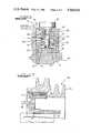
- FIG. 1is a partial longitudinal cross-sectional view through an accessory drive arrangement constructed accordingly to this invention
- FIG. 2is an enlarged cross-sectional view of an hydraulic governor illustrated generally in FIG. 1;
- FIG. 3is a partial cross-sectional illustration showing a one-way clutch bearing between the driven shaft and the accessory pulley;
- FIG. 4is a graph illustrating the idealized relational of accessory speed, oil pump pressure and governor pressure to engine speed.
- FIG. 5is a chart illustrating the idealized ratio relationship between the pulleys of the pulley transmission at selected engine speed.
- the accessory drive system 10 of this inventionis of the variable pulley type as illustrated in FIG. 1 and comprises a drive pulley 12 and a driven pulley 14 drivingly interconnected by a power transmission belt 16.
- Drive pulley 12comprises an axially movable flange 18 and an axially fixed flange 20, the fixed flange 20 having a rearwardly extending flanged, cylindrical part 22 connected to a generally cylindrical flange member 24 by a plurality of machine screws 26 and bolted by machine bolt 28 to the crankshaft 30 driven by an engine (FIG. 1).
- the axially movable flange 18has a hub 32 slidably received on a flanged stub shaft 34 to which a spider 36 is attached by a machine screw 38.
- a Belleville spring 40connected to tangs 37 of the spider 36 and the outside of the flange 18, biases the flange 18 toward the flange 20.
- a piston 42 in a cavity 44 formed by the cylindrical part 22 and the flange member 24has a plurality of relatively long, forwardly extending, cylindrical spacers 46 connected to hub 32 by bolts 47, each spacer 46 being slidably received in suitable openings 48, 50 in the stub shaft 34 and axially fixed flange 20, respectively.
- the spacers 46 and their relation to the pulley flangesinsures concurrent rotation of the axially movable flange 18 with the flange 20.
- a flexible diaphragm 52is sealed between the parts 22 and 24 and is attached to the piston 42.
- the diaphragmdivides the cavity 44 into a pressure space 44A and a vented space 44B.
- the space 44Bis vented to the atmosphere by a vent opening 54 in the part 22.
- a counterbalanced, two stage hydraulic governor 56(FIG. 2) is connected to the crankshaft 30 and controls the flow of modulated engine crankcase oil through passage 90 and opening 92 into the pressure space 44A.
- the hydraulic governor 56comprises a housing or body 58 with a radial bore 60 intersected by ports 62, 64 and 66.
- a generally cylindrical valve spool 68is slidably received in bore 60 and has an encircling groove 70 between a first land 72 of a first diameter and a second land 74 of a second and smaller diameter. The difference between the two valve spool diameters provides differential area 75, the function of which will be later described.
- the valve spool 68also has a pocket 76 to receive a coil spring 78 surrounding a radial, cylindrical stem 80 carrying at one end a washer 82 to constrain the spring 78, and a flyweight 84 at the other and radially outwardly end.
- Port 62is connected to passageway 86 which in turn is connected to passageway 88 in the crankshaft 30. Passageway 88 is connected to the engine oil pump of FIG. 1 for the flow of engine crankcase oil to the port 62.
- Port 64is connected to an axially oriented passage 90 and opening 92 in flange member 24. Port 64, passage 90 and opening 92 permit the flow of modulated crankcase oil to pressure chamber 44A when ports 64 and 62 are connected by means of groove 70, thus moving pulley flange 18 axially relative to pulley flange 20.
- Port 66is connected to passageway 94 in housing 58 and to passageway 96 in the crankshaft 30 to permit the return flow of oil to the crankcase when the groove 70 of the valve spool 68 bridges the ports 66 and 64.
- the driven pulley 14(FIG. 1) comprises an axially fixed flange 98 and an axially movable flange 100, the former being connected to a stub shaft 102 carrying a multiple groove pulley 104 journalled in spaced bearings 106, 108 in a support 110 fixed to the vehicle (not shown).
- a machine screw 112 and washer 114position the pulley 104 and splined stub shaft 102 with respect to the support 110.
- the axially movable flange 100is connected to a hub 116 axially slidable on stub shaft 102.
- a Belleville spring 118which may have the same or a different spring rate than spring 40, is connected at its central portion to tangs 103 of the pulley 104 and at its outer rim to the rim of the pulley flange 100.
- the spring 118biases the axially movable flange 100 toward the axially fixed flange 98, and the multiple groove pulley 104 is the driving pulley for the accessories (not shown).
- the cooling fan 120 for the engineis connected to the axially fixed pulley 98.
- a two piece multiple pulley system 134can be substituted for the pulley 104 in the FIG. 1 embodiment.
- the pulley system 134comprises a hub member 136, which encircles and is connected to the stub shaft 102 (a portion of which is shown in broken lines), having tangs 138 for engaging the Belleville spring 118.
- the system 134also comprises a multiple pulley 140 which encircles hub member 136.
- a one way clutch/bearing 142 of conventional constructionis located between hub member 136 and pulley 140 and permits pulley 140 to freewheel during upshifts.
- FIGS. 1, 2, 4 and 5the pressure of the oil from the pump (pump pressure) is regulated to provide uniform pressure over the engine operating speed range in a conventional manner by using a pressure regulator valve in the system.
- pump pressurerises at a rapid rate as engine speed increases to slightly above idle speed (in the example illustrated) after which it becomes substantially uniform for engine speeds above idle speed.
- the point at which the pump pressure levels offis determined by the pressure regulator valve, pump displacement and the lubricating load.
- the rotational speed of the accessory pulley 104rises sharply to a top speed which occurs at about engine idle speed and then it levels off and remains fairly constant between idle and 3000 rpm. The accessory speed then rises at a rate less sharp above 3000 rpm.
- Oil pressure operating on the differential area 75 (FIG. 2) of the valve spool 68balances the forces of the governor weight 84 and associated components for each speed of rotation of the crankshaft 30.
- the initial rapid pressure riseis the result of rapid changes in the length of spring 78 which permits the weight 84 to move out quickly to a larger spinning radius. This action increases the rate of pressure rise shown in the first stage "governor" pressure curve of FIG. 4.
- the spring 78has bottomed, so that the spring 78 no longer has an effect on the governor pressure variation.
- the rate of governor pressure risedecreases in the second curve segment because the weight 84 and associated components rotate at a more or less fixed radius and thus no longer move out rapidly relative to the spool valve control overlapping ports.
- the relative drive ratios of the pulleysis correlated to the engine speeds in FIG. 5.
- the maximum underdrive ratiooccurs at about an engine speed of 3000 rpm, and is the same for engine speeds above 3000 rpm because of the limits imposed by the pulley designs.
- Pulley ratio changesare controlled gradually by the governor between overdrive and underdrive.
Landscapes
- Engineering & Computer Science (AREA)
- General Engineering & Computer Science (AREA)
- Mechanical Engineering (AREA)
- Chemical & Material Sciences (AREA)
- Combustion & Propulsion (AREA)
- Transmissions By Endless Flexible Members (AREA)
Abstract
Description
Claims (5)
Priority Applications (1)
| Application Number | Priority Date | Filing Date | Title |
|---|---|---|---|
| US06/615,630US4569670A (en) | 1984-05-31 | 1984-05-31 | Variable pulley accessory drive |
Applications Claiming Priority (1)
| Application Number | Priority Date | Filing Date | Title |
|---|---|---|---|
| US06/615,630US4569670A (en) | 1984-05-31 | 1984-05-31 | Variable pulley accessory drive |
Publications (1)
| Publication Number | Publication Date |
|---|---|
| US4569670Atrue US4569670A (en) | 1986-02-11 |
Family
ID=24466208
Family Applications (1)
| Application Number | Title | Priority Date | Filing Date |
|---|---|---|---|
| US06/615,630Expired - Fee RelatedUS4569670A (en) | 1984-05-31 | 1984-05-31 | Variable pulley accessory drive |
Country Status (1)
| Country | Link |
|---|---|
| US (1) | US4569670A (en) |
Cited By (41)
| Publication number | Priority date | Publication date | Assignee | Title |
|---|---|---|---|---|
| GB2220038A (en)* | 1988-06-28 | 1989-12-28 | Christopher David Whelan | A constant speed drive for electrical generators |
| US5201687A (en)* | 1989-11-21 | 1993-04-13 | Luk Lamellen Und Kupplungsbau Gmbh | Continuously variable transmission with hydraulically adjustable sheaves |
| EP0517185A3 (en)* | 1991-06-05 | 1993-07-28 | Tesma International Inc | Serpentine drive with coil spring one-way clutch alternator connection |
| ES2110335A1 (en)* | 1993-03-30 | 1998-02-01 | Sipra Patent Beteiligung | Draw-off device with adjustable tension for circular knitting machine |
| US20090069150A1 (en)* | 2007-09-10 | 2009-03-12 | Tao Zhixin | Dual-cylinder gasoline engine with a centrifugal clutch |
| US20150226323A1 (en)* | 2006-06-26 | 2015-08-13 | Fallbrook Intellectual Property Company Llc | Continuously variable transmission |
| US9574642B2 (en) | 2008-10-14 | 2017-02-21 | Fallbrook Intellectual Property Company Llc | Continuously variable transmission |
| US9574643B2 (en) | 2007-04-24 | 2017-02-21 | Fallbrook Intellectual Property Company Llc | Electric traction drives |
| US9618100B2 (en) | 2008-05-07 | 2017-04-11 | Fallbrook Intellectual Property Company Llc | Assemblies and methods for clamping force generation |
| US9677650B2 (en) | 2013-04-19 | 2017-06-13 | Fallbrook Intellectual Property Company Llc | Continuously variable transmission |
| US9676391B2 (en) | 2007-02-01 | 2017-06-13 | Fallbrook Intellectual Property Company Llc | Systems and methods for control of transmission and/or prime mover |
| US9683638B2 (en) | 2005-12-30 | 2017-06-20 | Fallbrook Intellectual Property Company Llc | Continuously variable gear transmission |
| US9683640B2 (en) | 2008-06-06 | 2017-06-20 | Fallbrook Intellectual Property Company Llc | Infinitely variable transmissions, continuously variable transmissions, methods, assemblies, subassemblies, and components therefor |
| US9709138B2 (en) | 2005-11-22 | 2017-07-18 | Fallbrook Intellectual Property Company Llc | Continuously variable transmission |
| US9739375B2 (en) | 2007-12-21 | 2017-08-22 | Fallbrook Intellectual Property Company Llc | Automatic transmissions and methods therefor |
| US9850993B2 (en) | 2008-02-29 | 2017-12-26 | Fallbrook Intellectual Property Company Llc | Continuously and/or infinitely variable transmissions and methods therefor |
| US9869388B2 (en) | 2007-07-05 | 2018-01-16 | Fallbrook Intellectual Property Company Llc | Continuously variable transmission |
| US9878717B2 (en) | 2008-08-05 | 2018-01-30 | Fallbrook Intellectual Property Company Llc | Systems and methods for control of transmission and/or prime mover |
| US9903450B2 (en) | 2008-08-26 | 2018-02-27 | Fallbrook Intellectual Property Company Llc | Continuously variable transmission |
| US9920823B2 (en) | 2009-04-16 | 2018-03-20 | Fallbrook Intellectual Property Company Llc | Continuously variable transmission |
| US9945456B2 (en) | 2007-06-11 | 2018-04-17 | Fallbrook Intellectual Property Company Llc | Continuously variable transmission |
| US9950608B2 (en) | 2005-10-28 | 2018-04-24 | Fallbrook Intellectual Property Company Llc | Electromotive drives |
| US10036453B2 (en) | 2004-10-05 | 2018-07-31 | Fallbrook Intellectual Property Company Llc | Continuously variable transmission |
| US10047861B2 (en) | 2016-01-15 | 2018-08-14 | Fallbrook Intellectual Property Company Llc | Systems and methods for controlling rollback in continuously variable transmissions |
| US10054201B2 (en)* | 2015-03-12 | 2018-08-21 | GM Global Technology Operations LLC | Variable speed accessory drive |
| US10066712B2 (en) | 2010-03-03 | 2018-09-04 | Fallbrook Intellectual Property Company Llc | Infinitely variable transmissions, continuously variable transmissions, methods, assemblies, subassemblies, and components therefor |
| US10066713B2 (en) | 2008-06-23 | 2018-09-04 | Fallbrook Intellectual Property Company Llc | Continuously variable transmission |
| US10094453B2 (en) | 2007-02-16 | 2018-10-09 | Fallbrook Intellectual Property Company Llc | Infinitely variable transmissions, continuously variable transmissions, methods, assemblies, subassemblies, and components therefor |
| US10100927B2 (en) | 2007-11-16 | 2018-10-16 | Fallbrook Intellectual Property Company Llc | Controller for variable transmission |
| US10197147B2 (en) | 2010-11-10 | 2019-02-05 | Fallbrook Intellectual Property Company Llc | Continuously variable transmission |
| US10208840B2 (en) | 2005-12-09 | 2019-02-19 | Fallbrook Intellectual Property Company Llc | Continuously variable transmission |
| US10260607B2 (en) | 2007-02-12 | 2019-04-16 | Fallbrook Intellectual Property Company Llc | Continuously variable transmissions and methods therefor |
| US10400872B2 (en) | 2015-03-31 | 2019-09-03 | Fallbrook Intellectual Property Company Llc | Balanced split sun assemblies with integrated differential mechanisms, and variators and drive trains including balanced split sun assemblies |
| US10428915B2 (en) | 2012-01-23 | 2019-10-01 | Fallbrook Intellectual Property Company Llc | Infinitely variable transmissions, continuously variable transmissions, methods, assemblies, subassemblies, and components therefor |
| US10428939B2 (en) | 2003-02-28 | 2019-10-01 | Fallbrook Intellectual Property Company Llc | Continuously variable transmission |
| US10458526B2 (en) | 2016-03-18 | 2019-10-29 | Fallbrook Intellectual Property Company Llc | Continuously variable transmissions, systems and methods |
| US10473195B2 (en)* | 2017-06-06 | 2019-11-12 | GM Global Technology Operations LLC | Continuously-variable transmission |
| US11174922B2 (en) | 2019-02-26 | 2021-11-16 | Fallbrook Intellectual Property Company Llc | Reversible variable drives and systems and methods for control in forward and reverse directions |
| US11215268B2 (en) | 2018-11-06 | 2022-01-04 | Fallbrook Intellectual Property Company Llc | Continuously variable transmissions, synchronous shifting, twin countershafts and methods for control of same |
| US11667351B2 (en) | 2016-05-11 | 2023-06-06 | Fallbrook Intellectual Property Company Llc | Systems and methods for automatic configuration and automatic calibration of continuously variable transmissions and bicycles having continuously variable transmission |
| US12442434B2 (en) | 2024-06-04 | 2025-10-14 | Enviolo B.V. | Reversible variable drives and systems and methods for control in forward and reverse directions |
Citations (10)
| Publication number | Priority date | Publication date | Assignee | Title |
|---|---|---|---|---|
| US2909071A (en)* | 1956-05-23 | 1959-10-20 | Chrysler Corp | Variable speed accessory drive |
| US3403567A (en)* | 1964-08-26 | 1968-10-01 | Cazeneuve Sa | V-belt speed-changing mechanisms operated by liquid under pressure |
| US3893343A (en)* | 1972-11-21 | 1975-07-08 | Daimler Benz Ag | Controllable aggregate-drive for internal combustion engines |
| US3906808A (en)* | 1972-12-13 | 1975-09-23 | Daimler Benz Ag | Controllable aggregate-drive for internal combustion engines, especially for motor vehicle internal combustion engines |
| US4100818A (en)* | 1976-09-13 | 1978-07-18 | Borg-Warner Corporation | Drive system |
| US4228691A (en)* | 1977-03-01 | 1980-10-21 | Borg-Warner Corporation | Variable pulley transmission |
| US4229988A (en)* | 1977-10-06 | 1980-10-28 | P.I.V. Antrieb Reimers Kommanditgesellschaft | Continuously variable cone pulley belt-drive gearing |
| US4345664A (en)* | 1979-05-23 | 1982-08-24 | Honda Giken Kogyo Kabushiki Kaisha | Power transmission for two-wheeled vehicle |
| US4384862A (en)* | 1979-07-02 | 1983-05-24 | Aisin Seiki Kabushiki Kaisha | Centrifugal operating device |
| US4410312A (en)* | 1978-08-21 | 1983-10-18 | Thirion De Briel Jacques | Speed change device |
- 1984
- 1984-05-31USUS06/615,630patent/US4569670A/ennot_activeExpired - Fee Related
Patent Citations (10)
| Publication number | Priority date | Publication date | Assignee | Title |
|---|---|---|---|---|
| US2909071A (en)* | 1956-05-23 | 1959-10-20 | Chrysler Corp | Variable speed accessory drive |
| US3403567A (en)* | 1964-08-26 | 1968-10-01 | Cazeneuve Sa | V-belt speed-changing mechanisms operated by liquid under pressure |
| US3893343A (en)* | 1972-11-21 | 1975-07-08 | Daimler Benz Ag | Controllable aggregate-drive for internal combustion engines |
| US3906808A (en)* | 1972-12-13 | 1975-09-23 | Daimler Benz Ag | Controllable aggregate-drive for internal combustion engines, especially for motor vehicle internal combustion engines |
| US4100818A (en)* | 1976-09-13 | 1978-07-18 | Borg-Warner Corporation | Drive system |
| US4228691A (en)* | 1977-03-01 | 1980-10-21 | Borg-Warner Corporation | Variable pulley transmission |
| US4229988A (en)* | 1977-10-06 | 1980-10-28 | P.I.V. Antrieb Reimers Kommanditgesellschaft | Continuously variable cone pulley belt-drive gearing |
| US4410312A (en)* | 1978-08-21 | 1983-10-18 | Thirion De Briel Jacques | Speed change device |
| US4345664A (en)* | 1979-05-23 | 1982-08-24 | Honda Giken Kogyo Kabushiki Kaisha | Power transmission for two-wheeled vehicle |
| US4384862A (en)* | 1979-07-02 | 1983-05-24 | Aisin Seiki Kabushiki Kaisha | Centrifugal operating device |
Cited By (63)
| Publication number | Priority date | Publication date | Assignee | Title |
|---|---|---|---|---|
| GB2220038A (en)* | 1988-06-28 | 1989-12-28 | Christopher David Whelan | A constant speed drive for electrical generators |
| US5201687A (en)* | 1989-11-21 | 1993-04-13 | Luk Lamellen Und Kupplungsbau Gmbh | Continuously variable transmission with hydraulically adjustable sheaves |
| EP0517185A3 (en)* | 1991-06-05 | 1993-07-28 | Tesma International Inc | Serpentine drive with coil spring one-way clutch alternator connection |
| ES2110335A1 (en)* | 1993-03-30 | 1998-02-01 | Sipra Patent Beteiligung | Draw-off device with adjustable tension for circular knitting machine |
| US10428939B2 (en) | 2003-02-28 | 2019-10-01 | Fallbrook Intellectual Property Company Llc | Continuously variable transmission |
| US10036453B2 (en) | 2004-10-05 | 2018-07-31 | Fallbrook Intellectual Property Company Llc | Continuously variable transmission |
| US9950608B2 (en) | 2005-10-28 | 2018-04-24 | Fallbrook Intellectual Property Company Llc | Electromotive drives |
| US9709138B2 (en) | 2005-11-22 | 2017-07-18 | Fallbrook Intellectual Property Company Llc | Continuously variable transmission |
| US10711869B2 (en) | 2005-11-22 | 2020-07-14 | Fallbrook Intellectual Property Company Llc | Continuously variable transmission |
| US11454303B2 (en) | 2005-12-09 | 2022-09-27 | Fallbrook Intellectual Property Company Llc | Continuously variable transmission |
| US10208840B2 (en) | 2005-12-09 | 2019-02-19 | Fallbrook Intellectual Property Company Llc | Continuously variable transmission |
| US11598397B2 (en) | 2005-12-30 | 2023-03-07 | Fallbrook Intellectual Property Company Llc | Continuously variable gear transmission |
| US9683638B2 (en) | 2005-12-30 | 2017-06-20 | Fallbrook Intellectual Property Company Llc | Continuously variable gear transmission |
| US20150226323A1 (en)* | 2006-06-26 | 2015-08-13 | Fallbrook Intellectual Property Company Llc | Continuously variable transmission |
| US9726282B2 (en)* | 2006-06-26 | 2017-08-08 | Fallbrook Intellectual Property Company Llc | Continuously variable transmission |
| US9676391B2 (en) | 2007-02-01 | 2017-06-13 | Fallbrook Intellectual Property Company Llc | Systems and methods for control of transmission and/or prime mover |
| US10703372B2 (en) | 2007-02-01 | 2020-07-07 | Fallbrook Intellectual Property Company Llc | Systems and methods for control of transmission and/or prime mover |
| US9878719B2 (en) | 2007-02-01 | 2018-01-30 | Fallbrook Intellectual Property Company Llc | Systems and methods for control of transmission and/or prime mover |
| US10260607B2 (en) | 2007-02-12 | 2019-04-16 | Fallbrook Intellectual Property Company Llc | Continuously variable transmissions and methods therefor |
| US10094453B2 (en) | 2007-02-16 | 2018-10-09 | Fallbrook Intellectual Property Company Llc | Infinitely variable transmissions, continuously variable transmissions, methods, assemblies, subassemblies, and components therefor |
| US9574643B2 (en) | 2007-04-24 | 2017-02-21 | Fallbrook Intellectual Property Company Llc | Electric traction drives |
| US10056811B2 (en) | 2007-04-24 | 2018-08-21 | Fallbrook Intellectual Property Company Llc | Electric traction drives |
| US9945456B2 (en) | 2007-06-11 | 2018-04-17 | Fallbrook Intellectual Property Company Llc | Continuously variable transmission |
| US10260629B2 (en) | 2007-07-05 | 2019-04-16 | Fallbrook Intellectual Property Company Llc | Continuously variable transmission |
| US9869388B2 (en) | 2007-07-05 | 2018-01-16 | Fallbrook Intellectual Property Company Llc | Continuously variable transmission |
| US20090069150A1 (en)* | 2007-09-10 | 2009-03-12 | Tao Zhixin | Dual-cylinder gasoline engine with a centrifugal clutch |
| US11125329B2 (en) | 2007-11-16 | 2021-09-21 | Fallbrook Intellectual Property Company Llc | Controller for variable transmission |
| US10100927B2 (en) | 2007-11-16 | 2018-10-16 | Fallbrook Intellectual Property Company Llc | Controller for variable transmission |
| US9739375B2 (en) | 2007-12-21 | 2017-08-22 | Fallbrook Intellectual Property Company Llc | Automatic transmissions and methods therefor |
| US10704687B2 (en) | 2007-12-21 | 2020-07-07 | Fallbrook Intellectual Property Company Llc | Automatic transmissions and methods therefor |
| US9850993B2 (en) | 2008-02-29 | 2017-12-26 | Fallbrook Intellectual Property Company Llc | Continuously and/or infinitely variable transmissions and methods therefor |
| US9618100B2 (en) | 2008-05-07 | 2017-04-11 | Fallbrook Intellectual Property Company Llc | Assemblies and methods for clamping force generation |
| US9683640B2 (en) | 2008-06-06 | 2017-06-20 | Fallbrook Intellectual Property Company Llc | Infinitely variable transmissions, continuously variable transmissions, methods, assemblies, subassemblies, and components therefor |
| US10634224B2 (en) | 2008-06-06 | 2020-04-28 | Fallbrook Intellectual Property Company Llc | Infinitely variable transmissions, continuously variable transmissions, methods, assemblies, subassemblies, and components therefor |
| US10066713B2 (en) | 2008-06-23 | 2018-09-04 | Fallbrook Intellectual Property Company Llc | Continuously variable transmission |
| US9878717B2 (en) | 2008-08-05 | 2018-01-30 | Fallbrook Intellectual Property Company Llc | Systems and methods for control of transmission and/or prime mover |
| US9903450B2 (en) | 2008-08-26 | 2018-02-27 | Fallbrook Intellectual Property Company Llc | Continuously variable transmission |
| US10704657B2 (en) | 2008-08-26 | 2020-07-07 | Fallbrook Intellectual Property Company Llc | Continuously variable transmission |
| US10253880B2 (en) | 2008-10-14 | 2019-04-09 | Fallbrook Intellectual Property Company Llc | Continuously variable transmission |
| US9574642B2 (en) | 2008-10-14 | 2017-02-21 | Fallbrook Intellectual Property Company Llc | Continuously variable transmission |
| US9920823B2 (en) | 2009-04-16 | 2018-03-20 | Fallbrook Intellectual Property Company Llc | Continuously variable transmission |
| US10746270B2 (en) | 2009-04-16 | 2020-08-18 | Fallbrook Intellectual Property Company Llc | Continuously variable transmission |
| US10066712B2 (en) | 2010-03-03 | 2018-09-04 | Fallbrook Intellectual Property Company Llc | Infinitely variable transmissions, continuously variable transmissions, methods, assemblies, subassemblies, and components therefor |
| US10197147B2 (en) | 2010-11-10 | 2019-02-05 | Fallbrook Intellectual Property Company Llc | Continuously variable transmission |
| US10428915B2 (en) | 2012-01-23 | 2019-10-01 | Fallbrook Intellectual Property Company Llc | Infinitely variable transmissions, continuously variable transmissions, methods, assemblies, subassemblies, and components therefor |
| US10323732B2 (en) | 2013-04-19 | 2019-06-18 | Fallbrook Intellectual Property Company Llc | Continuously variable transmission |
| US9677650B2 (en) | 2013-04-19 | 2017-06-13 | Fallbrook Intellectual Property Company Llc | Continuously variable transmission |
| US10054201B2 (en)* | 2015-03-12 | 2018-08-21 | GM Global Technology Operations LLC | Variable speed accessory drive |
| US10400872B2 (en) | 2015-03-31 | 2019-09-03 | Fallbrook Intellectual Property Company Llc | Balanced split sun assemblies with integrated differential mechanisms, and variators and drive trains including balanced split sun assemblies |
| US10047861B2 (en) | 2016-01-15 | 2018-08-14 | Fallbrook Intellectual Property Company Llc | Systems and methods for controlling rollback in continuously variable transmissions |
| US11306818B2 (en) | 2016-01-15 | 2022-04-19 | Fallbrook Intellectual Property Company Llc | Systems and methods for controlling rollback in continuously variable transmissions |
| US10920882B2 (en) | 2016-01-15 | 2021-02-16 | Fallbrook Intellectual Property Company Llc | Systems and methods for controlling rollback in continuously variable transmissions |
| US10458526B2 (en) | 2016-03-18 | 2019-10-29 | Fallbrook Intellectual Property Company Llc | Continuously variable transmissions, systems and methods |
| US11667351B2 (en) | 2016-05-11 | 2023-06-06 | Fallbrook Intellectual Property Company Llc | Systems and methods for automatic configuration and automatic calibration of continuously variable transmissions and bicycles having continuously variable transmission |
| US12145690B2 (en) | 2016-05-11 | 2024-11-19 | Enviolo B.V. | Systems and methods for automatic configuration and automatic calibration of continuously variable transmissions and bicycles having continuously variable transmissions |
| US10473195B2 (en)* | 2017-06-06 | 2019-11-12 | GM Global Technology Operations LLC | Continuously-variable transmission |
| US11215268B2 (en) | 2018-11-06 | 2022-01-04 | Fallbrook Intellectual Property Company Llc | Continuously variable transmissions, synchronous shifting, twin countershafts and methods for control of same |
| US11624432B2 (en) | 2018-11-06 | 2023-04-11 | Fallbrook Intellectual Property Company Llc | Continuously variable transmissions, synchronous shifting, twin countershafts and methods for control of same |
| US12173778B2 (en) | 2018-11-06 | 2024-12-24 | Enviolo B.V. | Continuously variable transmissions, synchronous shifting, twin countershafts and methods for control of same |
| US11530739B2 (en) | 2019-02-26 | 2022-12-20 | Fallbrook Intellectual Property Company Llc | Reversible variable drives and systems and methods for control in forward and reverse directions |
| US11174922B2 (en) | 2019-02-26 | 2021-11-16 | Fallbrook Intellectual Property Company Llc | Reversible variable drives and systems and methods for control in forward and reverse directions |
| US12000458B2 (en) | 2019-02-26 | 2024-06-04 | Fallbrook Intellectual Property Company Llc | Reversible variable drives and systems and methods for control in forward and reverse directions |
| US12442434B2 (en) | 2024-06-04 | 2025-10-14 | Enviolo B.V. | Reversible variable drives and systems and methods for control in forward and reverse directions |
Similar Documents
| Publication | Publication Date | Title |
|---|---|---|
| US4569670A (en) | Variable pulley accessory drive | |
| US5201687A (en) | Continuously variable transmission with hydraulically adjustable sheaves | |
| US4391156A (en) | Electric motor drive with infinitely variable speed transmission | |
| US5667448A (en) | Power train | |
| KR100254928B1 (en) | Clutch assembly for an automatic mechanical transmission | |
| US4018316A (en) | Engine and transmission power train | |
| US4655043A (en) | Turbocharger | |
| GB2043807A (en) | Variable pulley transmission | |
| CA2110506A1 (en) | Self-energized controllable belt tensioner | |
| US5256109A (en) | Drive device | |
| US4216678A (en) | Drive system | |
| US5484344A (en) | Stepless automatic variable transmission | |
| US4023425A (en) | Centrifugal fluid expansible pulley with manifold vacuum control means | |
| US2922314A (en) | Automatic planetary transmission and control therefor | |
| US5234376A (en) | Spiral spring of a torsional damper | |
| US4557705A (en) | Variable ratio drive | |
| US3157066A (en) | Variable speed accessory drive | |
| US5538110A (en) | Valving for vane damper | |
| US2986955A (en) | Fluid mechanical coupling | |
| US5226514A (en) | Mounting for rotating spiral spring | |
| US5360090A (en) | Valving for vane damper | |
| US4541513A (en) | Fluid power transmission | |
| US4632233A (en) | Torque converter equipped with lockup control unit | |
| US4485903A (en) | Centrifugal actuated friction clutch with a hydraulic apply piston | |
| US3033334A (en) | Bleed controlled fluid-mechanical coupling |
Legal Events
| Date | Code | Title | Description |
|---|---|---|---|
| AS | Assignment | Owner name:BORG-WARNER CORPORATION, 200 S. MICHIGAN AVE., CHI Free format text:ASSIGNMENT OF ASSIGNORS INTEREST.;ASSIGNOR:MC INTOSH, ARTHUR M.;REEL/FRAME:004308/0191 Effective date:19840521 | |
| FPAY | Fee payment | Year of fee payment:4 | |
| AS | Assignment | Owner name:BORG-WARNER CORPORATION, A DE CORP. Free format text:ASSIGNMENT OF ASSIGNORS INTEREST. EFFECTIVE AS OF DEC. 31, 1987;ASSIGNOR:BORG-WARNER AUTOMOTIVE, INC., A DE CORP.;REEL/FRAME:005287/0001 Effective date:19881122 | |
| AS | Assignment | Owner name:BORG-WARNER AUTOMOTIVE, INC. A CORP. OF DELAWARE, Free format text:ASSIGNMENT OF ASSIGNORS INTEREST.;ASSIGNOR:BORG-WARNER CORPORATION A CORP. OF DELAWARE;REEL/FRAME:006024/0061 Effective date:19920210 | |
| REMI | Maintenance fee reminder mailed | ||
| REMI | Maintenance fee reminder mailed | ||
| LAPS | Lapse for failure to pay maintenance fees | ||
| FP | Lapsed due to failure to pay maintenance fee | Effective date:19940213 | |
| STCH | Information on status: patent discontinuation | Free format text:PATENT EXPIRED DUE TO NONPAYMENT OF MAINTENANCE FEES UNDER 37 CFR 1.362 |