US4568243A - Vibration isolating seal for mounting fans and blowers - Google Patents
Vibration isolating seal for mounting fans and blowersDownload PDFInfo
- Publication number
- US4568243A US4568243AUS06/612,152US61215284AUS4568243AUS 4568243 AUS4568243 AUS 4568243AUS 61215284 AUS61215284 AUS 61215284AUS 4568243 AUS4568243 AUS 4568243A
- Authority
- US
- United States
- Prior art keywords
- frame
- frames
- fan
- disposed
- securable
- Prior art date
- Legal status (The legal status is an assumption and is not a legal conclusion. Google has not performed a legal analysis and makes no representation as to the accuracy of the status listed.)
- Expired - Lifetime
Links
- 239000012528membraneSubstances0.000claimsabstractdescription28
- 238000007789sealingMethods0.000claimsabstractdescription16
- 229920001971elastomerPolymers0.000claimsabstractdescription9
- 239000000806elastomerSubstances0.000claimsabstractdescription8
- 235000012459muffinsNutrition0.000claimsdescription6
- 230000003068static effectEffects0.000claimsdescription3
- 239000000463materialSubstances0.000description5
- 238000004519manufacturing processMethods0.000description4
- 229920000642polymerPolymers0.000description3
- 230000000694effectsEffects0.000description2
- 238000002955isolationMethods0.000description2
- 239000004033plasticSubstances0.000description2
- 238000005728strengtheningMethods0.000description2
- 239000000853adhesiveSubstances0.000description1
- 230000001070adhesive effectEffects0.000description1
- 230000005540biological transmissionEffects0.000description1
- 230000006835compressionEffects0.000description1
- 238000007906compressionMethods0.000description1
- 238000001816coolingMethods0.000description1
- 238000013016dampingMethods0.000description1
- 230000005284excitationEffects0.000description1
- 239000006260foamSubstances0.000description1
- -1for exampleSubstances0.000description1
- 239000002184metalSubstances0.000description1
- 239000002905metal composite materialSubstances0.000description1
- 238000000034methodMethods0.000description1
- 230000002093peripheral effectEffects0.000description1
- 231100000614poisonToxicity0.000description1
- 230000005855radiationEffects0.000description1
- 239000000126substanceSubstances0.000description1
- 229920001169thermoplasticPolymers0.000description1
- 239000004416thermosoftening plasticSubstances0.000description1
- 230000007704transitionEffects0.000description1
Images

Classifications
- F—MECHANICAL ENGINEERING; LIGHTING; HEATING; WEAPONS; BLASTING
- F04—POSITIVE - DISPLACEMENT MACHINES FOR LIQUIDS; PUMPS FOR LIQUIDS OR ELASTIC FLUIDS
- F04D—NON-POSITIVE-DISPLACEMENT PUMPS
- F04D29/00—Details, component parts, or accessories
- F04D29/66—Combating cavitation, whirls, noise, vibration or the like; Balancing
- F04D29/661—Combating cavitation, whirls, noise, vibration or the like; Balancing especially adapted for elastic fluid pumps
- F04D29/668—Combating cavitation, whirls, noise, vibration or the like; Balancing especially adapted for elastic fluid pumps damping or preventing mechanical vibrations
- F—MECHANICAL ENGINEERING; LIGHTING; HEATING; WEAPONS; BLASTING
- F04—POSITIVE - DISPLACEMENT MACHINES FOR LIQUIDS; PUMPS FOR LIQUIDS OR ELASTIC FLUIDS
- F04D—NON-POSITIVE-DISPLACEMENT PUMPS
- F04D29/00—Details, component parts, or accessories
- F04D29/02—Selection of particular materials
- F04D29/023—Selection of particular materials especially adapted for elastic fluid pumps
- F—MECHANICAL ENGINEERING; LIGHTING; HEATING; WEAPONS; BLASTING
- F04—POSITIVE - DISPLACEMENT MACHINES FOR LIQUIDS; PUMPS FOR LIQUIDS OR ELASTIC FLUIDS
- F04D—NON-POSITIVE-DISPLACEMENT PUMPS
- F04D29/00—Details, component parts, or accessories
- F04D29/60—Mounting; Assembling; Disassembling
- F04D29/64—Mounting; Assembling; Disassembling of axial pumps
- F04D29/644—Mounting; Assembling; Disassembling of axial pumps especially adapted for elastic fluid pumps
- F04D29/646—Mounting or removal of fans
- F—MECHANICAL ENGINEERING; LIGHTING; HEATING; WEAPONS; BLASTING
- F24—HEATING; RANGES; VENTILATING
- F24F—AIR-CONDITIONING; AIR-HUMIDIFICATION; VENTILATION; USE OF AIR CURRENTS FOR SCREENING
- F24F7/00—Ventilation
- F24F7/007—Ventilation with forced flow
- F24F7/013—Ventilation with forced flow using wall or window fans, displacing air through the wall or window
- F—MECHANICAL ENGINEERING; LIGHTING; HEATING; WEAPONS; BLASTING
- F05—INDEXING SCHEMES RELATING TO ENGINES OR PUMPS IN VARIOUS SUBCLASSES OF CLASSES F01-F04
- F05D—INDEXING SCHEME FOR ASPECTS RELATING TO NON-POSITIVE-DISPLACEMENT MACHINES OR ENGINES, GAS-TURBINES OR JET-PROPULSION PLANTS
- F05D2260/00—Function
- F05D2260/96—Preventing, counteracting or reducing vibration or noise
- F—MECHANICAL ENGINEERING; LIGHTING; HEATING; WEAPONS; BLASTING
- F05—INDEXING SCHEMES RELATING TO ENGINES OR PUMPS IN VARIOUS SUBCLASSES OF CLASSES F01-F04
- F05D—INDEXING SCHEME FOR ASPECTS RELATING TO NON-POSITIVE-DISPLACEMENT MACHINES OR ENGINES, GAS-TURBINES OR JET-PROPULSION PLANTS
- F05D2300/00—Materials; Properties thereof
- F05D2300/10—Metals, alloys or intermetallic compounds
- F05D2300/17—Alloys
- F05D2300/171—Steel alloys
Definitions
- This inventionrelates to fans and blowers, and more particularly to a vibration-isolating and sealing device for mounting same to, for example, metallic cabinets and enclosures housing operating electronic devices.
- heat sinkssuch as heat-conductive fins
- the electronic equipmentis typically packaged in a cabinet or enclosure which protects the devices but frequently provides minimal room within for convection cooling.
- the cabinetsare provided with fans which are, all too often, fastened directly to the cabinets, an arrangement known as "hard mounting”.
- the fansare generally known as "muffin fans” and typically comprise a propeller rotatably mounted within a frame on a hub containing the prime mover. In the four corners of the frame are disposed holes for receiving bolts which secure the fan to a panel of the cabinet.
- Hard-mountingcan result in the vibrational excitation of the cabinet at the one-per-revolution and blade-pass frequencies, and their respective harmonics, of the fan during operation as well as the power line frequency and its harmonics.
- This structure-borne component of noisecan be most undesirable for particular locations, such as when the electronic cabinets are within an office, and especially when several such fans are operating.
- annular foam insertTo fill the gap an annular foam insert has been used as a seal to channel the moving air and prevent its escape through the gap. This arrangement can be cumbersome and expensive, both in manufacture, repair and assembly.
- an object of the present inventionis to provide a vibration-isolating and mounting arrangement for fans and blowers.
- Another object of the present inventionis to provide a seal disposable between a device such as a fan or blower and a surface on which the device is mounted.
- a further object of the inventionis to provide a vibration-isolating and sealing means for mounting fans, blowers and the like and preventing the transmission of structure-borne noise.
- a still further object of the inventionis to provide a vibration-isolating and sealing means having a reduced profile or stand-off height.
- Yet another object of the present inventionis to provide a vibration-isolating and sealing means which is of simple design and can be economically manufactured and assembled.
- a vibration-isolating and sealing meansfor mounting a fan having a propeller, said means comprising an outer, substantially-square frame; an inner, substantially square frame disposed coaxially and radially within the outer frame; a generally "S" shaped flexural membrane disposed between and connecting said inner to said outer frame; said membrane being made of elastomer and said inner and outer frames being made of a plastic or elastomer material; means for flush mounting the fan on the inner frame, means for flush mounting the outer frame on a support surface, and wherein the inner frame has a central bore configured to channel air to the propeller of the fan.
- the vibration-isolating sealis made integrally with the housing of the fan.
- the mount, or mount and housing unitcan be manufactured, for example, by the process described in the Patent Application Ser. No. 198,792, now U.S. Pat. No. 4,385,025, filed on Oct. 20, 1980 and commonly assigned.
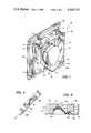
- FIG. 1is a perspective view of a fan including a fan housing incorporating a vibration-isolating seal made in accordance with the present invention
- FIG. 2is a top plan view of a vibration-isolating and sealing mount constructed in accordance with an embodiment of the invention
- FIG. 3is a side view in elevation of the vibration-isolating and sealing mount shown in FIG. 2;
- FIG. 4is a bottom plan view of the vibration-isolating and sealing mount shown in FIG. 2;
- FIG. 5is a sectional view taken along line V--V of FIG. 2;
- FIG. 6is a sectional view taken along line VI--VI of FIG. 4.
- a fan 10is shown as comprising a housing 12, a hub 14 fixedly connected to the housing by ribs 16, and a propeller 18, a term used in its broadest sense to include impellers, comprising an annular portion 20, and a plurality of circumferentially-spaced blades 22 radiating from and connected to the annular portion, said annular portion being rotatably mounted on said hub.
- hub 14includes therein a prime mover (not shown) such as a small electrical motor energized through leads 24.
- the fan housing 12includes a first flange element 26, a second flange element 28 in spaced parallel relation to the first flange element, and a cylindrical body 30 therebetween.
- the flange elements 26 and 28have central openings 27 and 29, respectively.
- the cylindrical body 30has a central circular opening 32 extending axially therethrough and in axial alignment with and of a diameter approximately equal to the openings 27 and 29. Opening 32 is further sized so as to have an axial extent greater than that of the blades 22 and a diameter sufficient to permit the unemcumbered rotation of the propeller 18. Preferably the diameter of the opening 32 is minimized and yet is sufficient to permit a clearance fit of the propeller 18 therein. Thus the opening 32 effectively channels air pushed or drawn by the propeller 18.
- the annular portion 20, for example,is disposed concentrically about the hub 14 over a portion of its axial extent, and the ribs 16 are peripherally-spaced and connected to the remaining axial extent of the hub proximate its planar end 34 closest to the first flange element 26.
- the flange elements 26 and 28are of a square geometry, extending radially beyond the body 30 at their corners, designated 40 and 42 respectively.
- Each of the corners 40 and corners 42can be provided with one of the axially-directed holes 44 and 46, respectively sized to accommodate therethrough bolts 45.
- the outer diameter of the body 30is equal to the length of a side of the square-shaped flange elements. Thus the overall size of the housing 12 as just described is minimized.
- FIG. 1Also illustrated in FIG. 1 is a device 50, made in accordance with the invention, which acts as a vibration-isolating seal, shroud and mount.
- the housing 12is fastened to the device 50 by bolts 45.
- other means for fasteningsuch as adhesive or tongue-and-slot are within the purview of the invention.
- the housingcan be integrally formed with the device 50. This shall be more fully described following the detailed description of device 50 below.
- FIGS. 2, 3, 4 and 5illustrate the device 50, which comprises an outer, substantially square frame 52; an inner, substantially square frame 54 disposed coaxially and radially within the outer frame; and a generally "S" shaped flexural membrane 56 disposed between and connecting said inner to said outer frame, and for example, structurally bonded therebetween.
- the shape of the membrane 56provides improved bond strength to the outer and inner frames 52 and 54, respectively, by increasing bond area. Further, the shape is dictated by operational requirements, namely, the shown configuration achieves approximately equal translational and coaxial stiffness and lower radial stiffness than a flat element would and thereby provides stable low-stiffness support of the fan 10 (FIG. 1).
- the membrane 56is made of elastomer and said inner and outer frames 52 and 54 are made of a substantially rigid or non-extensible material, for example, metal, polymer (plastic), an elastomer material more rigid (higher shear and Young's moduli) than said membrane material or a polymer metal composite.
- the membrane 56both supports the static and dynamic loads and provides a path-break for structure-borne noise and vibration.
- elastomeris used herein in its broader meaning to include various elastic substances which are rubber or rubber-like.
- the flexural membranefor example, has a static shear modulus in the range of 100 pounds per square inch and a Young's modulus for compression in the range of three times the shear modulus; hence the magnitude of Posion's ratio is 0.5.
- the membrane 56can be termed "visco-elastic", i.e., it has a broad yield range on its associated stress/strain curve and a "memory” so that it returns to its original shape after removal of applied forces. Its viscous nature provides its inherent hysteretic properties which result in dynamic energy loss or vibrational damping.
- the inner and outer frames 52 and 54 respectively,should be made substantially rigid though sufficiently deformable to achieve "sealing" between the outer frame 52 and a support surface (not shown) and the inner frame 54 and the fan 10 (FIG. 1) despite surface irregularities.
- the outer frame 52comprises four elongate elements 60, 61, 62, 63 of equal length, each one connected orthogonally at its ends to another of the elements so as to form a square.
- the elements 60, 61, 62, 63are molded integrally.
- the corners 64, 65, 66 and 67 between abutting ends of the elements 60-63, respectively,are each provided with bulbous projections 68, 69, 70, 71, respectively, extending radially outward.
- Axially directed holes 72, 73, 74, 75extend through the projections 68-71, respectively, and are sized and spaced to receive bolts or screws (not shown) therethrough, which fasten the device 50 to a support surface, for example, a panel of an electrical equipment cabinet (not shown).
- a strengthening flat 80is disposed about the periphery of the outer frame 52.
- the cross-sectional shape of elements 60-63can be gleaned from FIG. 6 which is a representative example. This figure is a sectional view taken along line VI--VI of FIG. 4 which is the bottom plan view.
- the element 62is shown in cross-section as having a planar bottom surface 82 with two orthogonally depending side walls 90 and 91.
- a surface 92 of element 62is not planar and does not extend axially to surface 84 except for a short transition piece 94 which connects the element 62 to the strengthening rib 80 which is disposed perpendicular thereto.
- the surface 92is curvaceous, having a generally "S" shaped silhouette for reasons hereinafter provided.
- the inner frame 54as shown in FIGS. 2 and 4 comprises four integrally-molded elongate elements 100, 101, 102, 103 of equal length, each one connected orthogonally at its ends to another of the elements so as to form a square. Corners 105, 106, 107, 108 between abutting ends of elements 100-103 are each provided with holes 110, 111, 112, 113 and crescent flats 115, 116, 117, 118, respectively. Holes 110-113 are sized and spaced to receive therethrough bolts 45 which fasten the fan 10 to the device 50. For example, the holes 110-113 can be threaded so as to receive the bolts 45 in threaded engagement.
- crescent flat 118, corner 108 and hole 113are shown in FIG. 5.
- the cross-sectional shape of elements 100-103can be gleaned from FIG. 6.
- the element 101is shown in cross-section as having a planar surface 119 substantially coplanar with surface 82, two depending side walls 120 and 122, and a surface 123 substantially coplanar with surface 84.
- the overall cross-sectional configurationis boot-like, with the radial extent or thickness of planar surface 123 being less than that of surface 119.
- Side wall 120is disposed perpendicularly to both surfaces 123 and 119.
- Side wall 122has a portion 125 which is parallel to side wall 120 and proximate to surface 119, and an arcuate portion 127 disposed between the portion 125 and surface 123.
- the crescent flats 115-118are planar elements having an axial extent less than the elements 100-103, and a radial extent from the corners 105-108 inward a distance sufficient to provide a substantially circular opening 120 (albeit with flattened sides 121, 122, 123, 124 though such are not necessary).
- the diameter of the circular opening 120should be approximately equal to the diameter of opening 32 in cylindrical body 30 of the fan housing 12 (FIG. 1).
- the openings 120, 27, 29 and 32act as cylindrical guides or shrouds which direct the air flow to or away from the propeller 18 (FIG. 1). This effectively reduces turbulent air flow and the resultant noise, and loss of efficiency of the fan 10 (FIG.
- the inventioncan be practiced with a variety of commercially available fans and blowers.
- the axial thickness and width of the membrane 56 (FIG. 5) and the shear and Young's moduli of elasticity characterizing the elastomer from which it is madecan be selected and designed in manufacture so that the device 50 (FIG. 1) can support the required weight while achieving the desired vibrational isolation at the particular band-pass frequencies.
- the followingis an example of performance and design for a typical application of the invention.
- a muffin fan of three inch diameter having seven blades and a weight of 0.86 lbs.may operate at speeds of 3,000 RPM (50 HZ).
- the device 50 constructed in accordance with the inventioncan be 4.6 inches square and 0.27 inches thick, with a natural frequency of 18 hertz, peak transmissibility of six to eight and an isolation efficiency (analyticly determined) of approximately 73% at 50 Hertz disturbance and approximately 99% at 350 Hz disturbance.
- housing 12 and mount 50are shown in FIG. 1 as separately formed elements joined by bolts 45, it should be understood that the invention also contemplates their manufacture as an integral, one-piece unit, and thus not require bolts 45. Such a vibration isolating and sealing housing would effect economies in manufacture and assembly.
- the device 50can be provided with two or more openings 120 so as to serve as a vibration isolating and sealing mount for two or more fans simultaneously.
- the device 50can be reconfigured into a circular or triangular form instead of the square as illustrated, if the application permits.
Landscapes
- Engineering & Computer Science (AREA)
- Mechanical Engineering (AREA)
- General Engineering & Computer Science (AREA)
- Chemical & Material Sciences (AREA)
- Combustion & Propulsion (AREA)
- Structures Of Non-Positive Displacement Pumps (AREA)
Abstract
Description
Claims (19)
Priority Applications (1)
| Application Number | Priority Date | Filing Date | Title |
|---|---|---|---|
| US06/612,152US4568243A (en) | 1981-10-08 | 1984-05-21 | Vibration isolating seal for mounting fans and blowers |
Applications Claiming Priority (2)
| Application Number | Priority Date | Filing Date | Title |
|---|---|---|---|
| US30974781A | 1981-10-08 | 1981-10-08 | |
| US06/612,152US4568243A (en) | 1981-10-08 | 1984-05-21 | Vibration isolating seal for mounting fans and blowers |
Related Parent Applications (1)
| Application Number | Title | Priority Date | Filing Date |
|---|---|---|---|
| US30974781AContinuation | 1981-10-08 | 1981-10-08 |
Publications (1)
| Publication Number | Publication Date |
|---|---|
| US4568243Atrue US4568243A (en) | 1986-02-04 |
Family
ID=26976981
Family Applications (1)
| Application Number | Title | Priority Date | Filing Date |
|---|---|---|---|
| US06/612,152Expired - LifetimeUS4568243A (en) | 1981-10-08 | 1984-05-21 | Vibration isolating seal for mounting fans and blowers |
Country Status (1)
| Country | Link |
|---|---|
| US (1) | US4568243A (en) |
Cited By (145)
| Publication number | Priority date | Publication date | Assignee | Title |
|---|---|---|---|---|
| US4655099A (en)* | 1985-02-26 | 1987-04-07 | Tri-Tech, Incorporated | Noiseless stepper motor |
| US4710096A (en)* | 1985-01-23 | 1987-12-01 | Rittal-Werk Rudolf Loh Gmbh & Co Kg | Fan mounting |
| USD297761S (en) | 1986-05-06 | 1988-09-20 | Manabu Shiraki | Axial fan |
| US4819503A (en)* | 1987-12-22 | 1989-04-11 | Unites States Of America As Represented By The Secretay Of The Navy | Low frequency structureborne vibration isolation mount |
| US4908929A (en)* | 1987-12-22 | 1990-03-20 | The United States Of America As Represented By The Secretary Of The Navy | Fabrication of low frequency structureborne vibration isolation mount |
| US5174318A (en)* | 1991-05-20 | 1992-12-29 | Whirlpool Corporation | Motor mount for domestic dishwasher |
| US5186605A (en)* | 1991-06-27 | 1993-02-16 | Compaq Computer Corporation | Computer cooling fan vibration isolation apparatus |
| US5208730A (en)* | 1991-06-27 | 1993-05-04 | Compaq Computer Corporation | Computer cooling fan vibration isolation apparatus |
| US5316423A (en)* | 1992-12-11 | 1994-05-31 | Kin Daniel C C | Acoustic isolation fastener and method for attachment |
| US5470363A (en)* | 1995-01-13 | 1995-11-28 | Envirco Corporation | Air blower and filter assemblies |
| US5906475A (en)* | 1997-11-12 | 1999-05-25 | Alcatel Usa Sourcing, L.P. | Housing for a fan |
| US6000919A (en)* | 1999-02-17 | 1999-12-14 | Hsieh; Hsin-Mao | Fan with reduced thickness |
| USD424186S (en) | 1999-06-28 | 2000-05-02 | Cooling device | |
| US6135875A (en)* | 1999-06-29 | 2000-10-24 | Emc Corporation | Electrical cabinet |
| US6193478B1 (en)* | 1998-09-23 | 2001-02-27 | Delta Electronics, Inc. | Construction of a fan |
| US6238181B1 (en)* | 1999-10-05 | 2001-05-29 | Andy Chen | Heat dissipating device for portable apparatus |
| US6254343B1 (en)* | 1999-12-06 | 2001-07-03 | Motorola, Inc. | Low-noise cooling fan for electronic components and method of making the same |
| CN1079506C (en)* | 1995-06-06 | 2002-02-20 | 松下精工株式会社 | Scavenge fan for window |
| US6351380B1 (en)* | 1999-11-12 | 2002-02-26 | Dell Products, L.P. | Cooling fan mounting arrangement |
| WO2002076787A3 (en)* | 2001-03-22 | 2003-06-05 | Infocus Corp | Projector housing with integral fan shroud |
| US20030156385A1 (en)* | 2002-02-15 | 2003-08-21 | Microsoft Corporation | Controlling thermal, acoustic, and/or electromagnetic properties of a computing device |
| US20030231956A1 (en)* | 2002-06-14 | 2003-12-18 | San-Yuan Lin | Illuminant Electric fan |
| US20040010351A1 (en)* | 2002-07-12 | 2004-01-15 | Ahmed Mohiuddin | Method and system for information handling system component mounting with vibration dampening |
| US6761343B2 (en) | 2001-06-13 | 2004-07-13 | York International Corp. | Single-piece motor mount |
| US20040173657A1 (en)* | 2002-09-12 | 2004-09-09 | Turk Robert L. | Fan motor suspension mount for a combustion-powered tool |
| US20040264129A1 (en)* | 2003-06-27 | 2004-12-30 | Lehman Bret W. | Vibration isolation of computing device heat sink fans from attached fan shrouds and heat sinks |
| US20050069407A1 (en)* | 2003-07-15 | 2005-03-31 | Ebm-Papst St. Georgen Gmbh & Co. Kg | Fan mounting means and method of making the same |
| US6894897B1 (en) | 2003-12-12 | 2005-05-17 | Lockheed Martin Corporation | Structure-borne noise isolation technique and apparatus for fans and blowers |
| US20050173997A1 (en)* | 2002-04-19 | 2005-08-11 | Schmid Alexandre C. | Mounting arrangement for a refrigerator fan |
| US20050207117A1 (en)* | 2002-05-21 | 2005-09-22 | Dell Products L.P. | Method and system for vibration dampening |
| US20050271515A1 (en)* | 2003-07-15 | 2005-12-08 | Ebm-Papst St George Gmbh & Co. Kg | Mini fan to be fixed in a recess of a wall |
| US20060002071A1 (en)* | 2004-07-05 | 2006-01-05 | Benq Corporation | Electronic apparatus having a vibration absorber |
| US20060039109A1 (en)* | 2004-08-18 | 2006-02-23 | Inventec Corporation | Miniaturized fan module |
| US20060133035A1 (en)* | 2004-12-17 | 2006-06-22 | Hon Hai Precision Industry Co., Ltd. | Cooling fan mounting arrangement with vibration isolation member |
| US20060250771A1 (en)* | 2005-05-06 | 2006-11-09 | Heine Optotechnik Gmbh & Co., Kg | Illuminating apparatus |
| US20070020120A1 (en)* | 2005-07-07 | 2007-01-25 | Oh Pil-Yong | Fan assembly to dampen fan vibration |
| US20070121290A1 (en)* | 2005-11-30 | 2007-05-31 | Datavan International Corp. | Detachable fan assembly |
| US20070154300A1 (en)* | 2005-12-30 | 2007-07-05 | Chien-Fa Liang | Fan vibration absorber device |
| US20070237602A1 (en)* | 2006-04-06 | 2007-10-11 | Foxconn Technology Co., Ltd. | Fan fastener for fastening a fan to a heat sink and method of using the same |
| US20070240869A1 (en)* | 2006-04-14 | 2007-10-18 | Fujitsu Limited | Electronic apparatus and cooling component |
| US20080179452A1 (en)* | 2007-01-25 | 2008-07-31 | Kinkopf Joseph W | Air Vehicle Propulsion System on Gimbaled Truss |
| US20080180911A1 (en)* | 2007-01-25 | 2008-07-31 | Sony Corporation | Fan motor apparatus and electronic apparatus |
| US20080259562A1 (en)* | 2007-04-23 | 2008-10-23 | Super Micro Computer, Inc. | Computer housing shock absorber device for a vibration source frame |
| US20090012003A1 (en)* | 1998-03-17 | 2009-01-08 | Genentech, Inc. | Polypeptides homologous to vegf and bmp1 |
| EP2060379A1 (en)* | 2007-11-16 | 2009-05-20 | Behr France Rouffach SAS | Vibration isolating support |
| EP2083176A1 (en) | 2008-01-25 | 2009-07-29 | EMB-Papst St. Georgen GmbH & Co. KG | Ventilation unit with an axial ventilator |
| US20090263242A1 (en)* | 2008-04-21 | 2009-10-22 | Wolfgang Arno Winkler | Fan arrangement |
| US20100074747A1 (en)* | 2008-09-22 | 2010-03-25 | Chien-Chun Yu | Mini axial fan with an improved core shaft structure |
| CN101061768B (en)* | 2004-11-16 | 2010-06-23 | 惠普开发有限公司 | Ventilated chassis and blade chassis for electronic devices |
| US20100225012A1 (en)* | 2009-03-04 | 2010-09-09 | Dyson Technology Limited | Humidifying apparatus |
| US20100226801A1 (en)* | 2009-03-04 | 2010-09-09 | Dyson Technology Limited | Fan assembly |
| US20100226749A1 (en)* | 2009-03-04 | 2010-09-09 | Dyson Technology Limited | Fan assembly |
| US20100226753A1 (en)* | 2009-03-04 | 2010-09-09 | Dyson Technology Limited | Fan assembly |
| US20100226769A1 (en)* | 2009-03-04 | 2010-09-09 | Dyson Technology Limited | Fan assembly |
| US20100226758A1 (en)* | 2009-03-04 | 2010-09-09 | Dyson Technology Limited | Fan assembly |
| US20100226763A1 (en)* | 2009-03-04 | 2010-09-09 | Dyson Technology Limited | Fan assembly |
| US20100226751A1 (en)* | 2009-03-04 | 2010-09-09 | Dyson Technology Limited | Fan assembly |
| US20100226764A1 (en)* | 2009-03-04 | 2010-09-09 | Dyson Technology Limited | Fan |
| US20100226797A1 (en)* | 2009-03-04 | 2010-09-09 | Dyson Technology Limited | Fan assembly |
| US20100226752A1 (en)* | 2009-03-04 | 2010-09-09 | Dyson Technology Limited | Fan assembly |
| US20100226754A1 (en)* | 2009-03-04 | 2010-09-09 | Dyson Technology Limited | Fan assembly |
| US7861708B1 (en)* | 2006-02-03 | 2011-01-04 | Fasco Industries, Inc. | Draft inducer blower mounting feature which reduces overall system vibration |
| US20110058935A1 (en)* | 2007-09-04 | 2011-03-10 | Dyson Technology Limited | Fan |
| US20110110805A1 (en)* | 2009-11-06 | 2011-05-12 | Dyson Technology Limited | Fan |
| US20110135882A1 (en)* | 2009-09-14 | 2011-06-09 | Stanley Joel A | System for Mounting Objects to Polymeric Membranes |
| US20110138602A1 (en)* | 2009-09-14 | 2011-06-16 | Stanley Joel A | System for Mounting Objects to Polymeric Membranes |
| US20110164959A1 (en)* | 2008-09-23 | 2011-07-07 | Dyson Technology Limited | Fan |
| US20110204195A1 (en)* | 2009-09-14 | 2011-08-25 | Stanley Joel A | System for Mounting Objects to Polymeric Membranes |
| US20110223014A1 (en)* | 2009-03-04 | 2011-09-15 | Dyson Technology Limited | Fan assembly |
| US20110236229A1 (en)* | 2010-03-23 | 2011-09-29 | Dyson Technology Limited | Accessory for a fan |
| US20120057959A1 (en)* | 2010-09-07 | 2012-03-08 | Dyson Technology Limited | Fan |
| EP1596072A3 (en)* | 2004-05-09 | 2012-04-25 | Rami Ben-Maimon | Vacuum pump vibration isolator |
| US20120195738A1 (en)* | 2011-01-28 | 2012-08-02 | Hon Hai Precision Industry Co., Ltd. | Shockproof fan apparatus |
| WO2012112637A1 (en)* | 2011-02-15 | 2012-08-23 | Stanley Joel A | System for mounting objects to polymeric membranes |
| US8348597B2 (en) | 2009-03-04 | 2013-01-08 | Dyson Technology Limited | Fan assembly |
| US8366403B2 (en) | 2010-08-06 | 2013-02-05 | Dyson Technology Limited | Fan assembly |
| TWI395876B (en)* | 2009-10-20 | 2013-05-11 | Yen Sun Technology Corp | Can absorb the vibration of the fan |
| GB2498344A (en)* | 2012-01-10 | 2013-07-17 | Greenwood Air Man Ltd | Fan mounting system |
| US8623158B2 (en) | 2009-09-14 | 2014-01-07 | Joel A. Stanley | System for mounting objects to polymeric membranes |
| US8734094B2 (en) | 2010-08-06 | 2014-05-27 | Dyson Technology Limited | Fan assembly |
| WO2014101936A1 (en)* | 2012-12-24 | 2014-07-03 | Arcelik Anonim Sirketi | Evaporator fan case fixing system for a refrigerator |
| US8873940B2 (en) | 2010-08-06 | 2014-10-28 | Dyson Technology Limited | Fan assembly |
| US8882451B2 (en) | 2010-03-23 | 2014-11-11 | Dyson Technology Limited | Fan |
| US8967980B2 (en) | 2010-10-18 | 2015-03-03 | Dyson Technology Limited | Fan assembly |
| US8967979B2 (en) | 2010-10-18 | 2015-03-03 | Dyson Technology Limited | Fan assembly |
| US9011116B2 (en) | 2010-05-27 | 2015-04-21 | Dyson Technology Limited | Device for blowing air by means of a nozzle assembly |
| USD728092S1 (en) | 2013-08-01 | 2015-04-28 | Dyson Technology Limited | Fan |
| USD728769S1 (en) | 2013-08-01 | 2015-05-05 | Dyson Technology Limited | Fan |
| USD728770S1 (en) | 2013-08-01 | 2015-05-05 | Dyson Technology Limited | Fan |
| USD729376S1 (en) | 2013-03-07 | 2015-05-12 | Dyson Technology Limited | Fan |
| USD729375S1 (en) | 2013-03-07 | 2015-05-12 | Dyson Technology Limited | Fan |
| USD729373S1 (en) | 2013-03-07 | 2015-05-12 | Dyson Technology Limited | Fan |
| USD729372S1 (en) | 2013-03-07 | 2015-05-12 | Dyson Technology Limited | Fan |
| USD729374S1 (en) | 2013-03-07 | 2015-05-12 | Dyson Technology Limited | Fan |
| USD729925S1 (en) | 2013-03-07 | 2015-05-19 | Dyson Technology Limited | Fan |
| US20150176189A1 (en)* | 2013-12-23 | 2015-06-25 | Dongbu Daewoo Electronics Corporation | Mounting unit for wall-mounted washing machine |
| US9121545B2 (en) | 2009-09-14 | 2015-09-01 | Bwdt, Llc | System for mounting objects to polymeric membranes |
| US9127855B2 (en) | 2011-07-27 | 2015-09-08 | Dyson Technology Limited | Fan assembly |
| US9151299B2 (en) | 2012-02-06 | 2015-10-06 | Dyson Technology Limited | Fan |
| US9175479B2 (en) | 2009-09-14 | 2015-11-03 | Bwdt, Llc | System for mounting objects to polymeric membranes |
| EP2822626A4 (en)* | 2012-03-06 | 2015-11-11 | Resmed Motor Technologies Inc | FLOW GENERATOR |
| USD746425S1 (en) | 2013-01-18 | 2015-12-29 | Dyson Technology Limited | Humidifier |
| USD746966S1 (en) | 2013-01-18 | 2016-01-05 | Dyson Technology Limited | Humidifier |
| USD747450S1 (en) | 2013-01-18 | 2016-01-12 | Dyson Technology Limited | Humidifier |
| US9249809B2 (en) | 2012-02-06 | 2016-02-02 | Dyson Technology Limited | Fan |
| USD749231S1 (en) | 2013-01-18 | 2016-02-09 | Dyson Technology Limited | Humidifier |
| US9283573B2 (en) | 2012-02-06 | 2016-03-15 | Dyson Technology Limited | Fan assembly |
| US9328739B2 (en) | 2012-01-19 | 2016-05-03 | Dyson Technology Limited | Fan |
| US9366449B2 (en) | 2012-03-06 | 2016-06-14 | Dyson Technology Limited | Humidifying apparatus |
| US9399872B2 (en) | 2009-09-14 | 2016-07-26 | Bwdt, Llc | System for mounting objects to polymeric membranes |
| US9410711B2 (en) | 2013-09-26 | 2016-08-09 | Dyson Technology Limited | Fan assembly |
| US9458853B2 (en) | 2011-07-27 | 2016-10-04 | Dyson Technology Limited | Fan assembly |
| US9513028B2 (en) | 2009-03-04 | 2016-12-06 | Dyson Technology Limited | Fan assembly |
| US9568021B2 (en) | 2012-05-16 | 2017-02-14 | Dyson Technology Limited | Fan |
| US9568006B2 (en) | 2012-05-16 | 2017-02-14 | Dyson Technology Limited | Fan |
| US9599356B2 (en) | 2014-07-29 | 2017-03-21 | Dyson Technology Limited | Humidifying apparatus |
| CN106762844A (en)* | 2015-11-24 | 2017-05-31 | 全亿大科技(佛山)有限公司 | Fan frame and the radiator fan with the fan frame |
| US9732763B2 (en) | 2012-07-11 | 2017-08-15 | Dyson Technology Limited | Fan assembly |
| US9745996B2 (en) | 2010-12-02 | 2017-08-29 | Dyson Technology Limited | Fan |
| US9745981B2 (en) | 2011-11-11 | 2017-08-29 | Dyson Technology Limited | Fan assembly |
| US9752789B2 (en) | 2012-03-06 | 2017-09-05 | Dyson Technology Limited | Humidifying apparatus |
| US9797414B2 (en) | 2013-07-09 | 2017-10-24 | Dyson Technology Limited | Fan assembly |
| US9797612B2 (en) | 2013-01-29 | 2017-10-24 | Dyson Technology Limited | Fan assembly |
| US9797613B2 (en) | 2012-03-06 | 2017-10-24 | Dyson Technology Limited | Humidifying apparatus |
| US9816531B2 (en) | 2008-10-25 | 2017-11-14 | Dyson Technology Limited | Fan utilizing coanda surface |
| US9822778B2 (en) | 2012-04-19 | 2017-11-21 | Dyson Technology Limited | Fan assembly |
| US9903602B2 (en) | 2014-07-29 | 2018-02-27 | Dyson Technology Limited | Humidifying apparatus |
| US9927136B2 (en) | 2012-03-06 | 2018-03-27 | Dyson Technology Limited | Fan assembly |
| US9926804B2 (en) | 2010-11-02 | 2018-03-27 | Dyson Technology Limited | Fan assembly |
| US9982677B2 (en) | 2014-07-29 | 2018-05-29 | Dyson Technology Limited | Fan assembly |
| US10094392B2 (en) | 2011-11-24 | 2018-10-09 | Dyson Technology Limited | Fan assembly |
| US10100836B2 (en) | 2010-10-13 | 2018-10-16 | Dyson Technology Limited | Fan assembly |
| US10145583B2 (en) | 2012-04-04 | 2018-12-04 | Dyson Technology Limited | Heating apparatus |
| US10408478B2 (en) | 2012-03-06 | 2019-09-10 | Dyson Technology Limited | Humidifying apparatus |
| US10428837B2 (en) | 2012-05-16 | 2019-10-01 | Dyson Technology Limited | Fan |
| US10465928B2 (en) | 2012-03-06 | 2019-11-05 | Dyson Technology Limited | Humidifying apparatus |
| US10612565B2 (en) | 2013-01-29 | 2020-04-07 | Dyson Technology Limited | Fan assembly |
| USD894367S1 (en)* | 2017-12-13 | 2020-08-25 | Ebm-Papst Mulfingen Gmbh & Co. Kg | Vent frame |
| US20200325913A1 (en)* | 2019-04-10 | 2020-10-15 | Haier Us Appliance Solutions, Inc. | Vibration isolating mounting of fan |
| US10914316B1 (en)* | 2011-08-23 | 2021-02-09 | Climatecraft, Inc. | Plenum fan |
| US10967712B2 (en)* | 2016-02-04 | 2021-04-06 | Kabushiki Kaisha Toyota Jidoshokki | Register panel mounting structure |
| US20220003246A1 (en)* | 2020-07-02 | 2022-01-06 | Dell Products, Lp | Information handling system with a vibration damping and air flow recirculation seal |
| US11537716B1 (en) | 2018-11-13 | 2022-12-27 | F5, Inc. | Methods for detecting changes to a firmware and devices thereof |
| US20230368763A1 (en)* | 2022-05-13 | 2023-11-16 | Martin Gossner | Anti-Vibration Fan Mounting Gasket |
| USD1009246S1 (en)* | 2019-05-29 | 2023-12-26 | Nidec Servo Corporation | Fan case |
Citations (15)
| Publication number | Priority date | Publication date | Assignee | Title |
|---|---|---|---|---|
| GB522231A (en)* | 1938-12-10 | 1940-06-12 | Mykas Adamcikas | Improvements relating to the mounting of screw fans |
| GB674280A (en)* | 1949-05-27 | 1952-06-18 | Ag Fuer Technische Studien | Device for sealing a space under super-atmospheric pressure situated between two coaxially arranged hollow machine parts |
| US2650021A (en)* | 1948-03-03 | 1953-08-25 | Wayne J Morrill | Housing for fan support |
| US2936141A (en)* | 1957-09-23 | 1960-05-10 | Illinois Tool Works | Resilient mount |
| GB883686A (en)* | 1958-04-01 | 1961-12-06 | Electrolux Ltd | Improvements in or relating to vacuum cleaners |
| GB897978A (en)* | 1957-11-13 | 1962-06-06 | Weatherfoil Heating Systems Lt | Improvements in or relating to heating and air conditioning apparatus |
| GB898002A (en)* | 1958-03-12 | 1962-06-06 | Silavent Ltd | Improvements relating to extraction fans |
| US3144859A (en)* | 1962-02-15 | 1964-08-18 | Young Radiator Co | Fan-shroud structure and mounting |
| US3161388A (en)* | 1962-02-28 | 1964-12-15 | Colchester Woods | Fan mountings |
| US3244105A (en)* | 1963-03-26 | 1966-04-05 | Gen Motors Corp | Pump for a domestic appliance |
| US3310698A (en)* | 1964-02-11 | 1967-03-21 | Imc Magnetics Corp | Machine frame for an electric motor |
| US3976393A (en)* | 1975-08-27 | 1976-08-24 | Candaian Hurricane Equipment Ltd | Portable fan housing |
| US4116171A (en)* | 1975-11-11 | 1978-09-26 | Motoren-Und Turbinen-Union Friedrichshafen Gmbh | Cooling device for an internal combustion engine |
| US4120271A (en)* | 1975-09-09 | 1978-10-17 | Motoren- Und Turbinen-Union Friedrichshafen Gmbh | Ventilating arrangement for an engine compartment |
| US4213426A (en)* | 1978-11-09 | 1980-07-22 | General Motors Corporation | Shrouding for engine mounted cooling fan |
- 1984
- 1984-05-21USUS06/612,152patent/US4568243A/ennot_activeExpired - Lifetime
Patent Citations (15)
| Publication number | Priority date | Publication date | Assignee | Title |
|---|---|---|---|---|
| GB522231A (en)* | 1938-12-10 | 1940-06-12 | Mykas Adamcikas | Improvements relating to the mounting of screw fans |
| US2650021A (en)* | 1948-03-03 | 1953-08-25 | Wayne J Morrill | Housing for fan support |
| GB674280A (en)* | 1949-05-27 | 1952-06-18 | Ag Fuer Technische Studien | Device for sealing a space under super-atmospheric pressure situated between two coaxially arranged hollow machine parts |
| US2936141A (en)* | 1957-09-23 | 1960-05-10 | Illinois Tool Works | Resilient mount |
| GB897978A (en)* | 1957-11-13 | 1962-06-06 | Weatherfoil Heating Systems Lt | Improvements in or relating to heating and air conditioning apparatus |
| GB898002A (en)* | 1958-03-12 | 1962-06-06 | Silavent Ltd | Improvements relating to extraction fans |
| GB883686A (en)* | 1958-04-01 | 1961-12-06 | Electrolux Ltd | Improvements in or relating to vacuum cleaners |
| US3144859A (en)* | 1962-02-15 | 1964-08-18 | Young Radiator Co | Fan-shroud structure and mounting |
| US3161388A (en)* | 1962-02-28 | 1964-12-15 | Colchester Woods | Fan mountings |
| US3244105A (en)* | 1963-03-26 | 1966-04-05 | Gen Motors Corp | Pump for a domestic appliance |
| US3310698A (en)* | 1964-02-11 | 1967-03-21 | Imc Magnetics Corp | Machine frame for an electric motor |
| US3976393A (en)* | 1975-08-27 | 1976-08-24 | Candaian Hurricane Equipment Ltd | Portable fan housing |
| US4120271A (en)* | 1975-09-09 | 1978-10-17 | Motoren- Und Turbinen-Union Friedrichshafen Gmbh | Ventilating arrangement for an engine compartment |
| US4116171A (en)* | 1975-11-11 | 1978-09-26 | Motoren-Und Turbinen-Union Friedrichshafen Gmbh | Cooling device for an internal combustion engine |
| US4213426A (en)* | 1978-11-09 | 1980-07-22 | General Motors Corporation | Shrouding for engine mounted cooling fan |
Non-Patent Citations (1)
| Title |
|---|
| Application Selection Guide, Barry Noise and Vibration Control, 1977.* |
Cited By (225)
| Publication number | Priority date | Publication date | Assignee | Title |
|---|---|---|---|---|
| US4710096A (en)* | 1985-01-23 | 1987-12-01 | Rittal-Werk Rudolf Loh Gmbh & Co Kg | Fan mounting |
| US4655099A (en)* | 1985-02-26 | 1987-04-07 | Tri-Tech, Incorporated | Noiseless stepper motor |
| USD297761S (en) | 1986-05-06 | 1988-09-20 | Manabu Shiraki | Axial fan |
| US4819503A (en)* | 1987-12-22 | 1989-04-11 | Unites States Of America As Represented By The Secretay Of The Navy | Low frequency structureborne vibration isolation mount |
| US4908929A (en)* | 1987-12-22 | 1990-03-20 | The United States Of America As Represented By The Secretary Of The Navy | Fabrication of low frequency structureborne vibration isolation mount |
| US5174318A (en)* | 1991-05-20 | 1992-12-29 | Whirlpool Corporation | Motor mount for domestic dishwasher |
| US5186605A (en)* | 1991-06-27 | 1993-02-16 | Compaq Computer Corporation | Computer cooling fan vibration isolation apparatus |
| US5208730A (en)* | 1991-06-27 | 1993-05-04 | Compaq Computer Corporation | Computer cooling fan vibration isolation apparatus |
| US5316423A (en)* | 1992-12-11 | 1994-05-31 | Kin Daniel C C | Acoustic isolation fastener and method for attachment |
| US5470363A (en)* | 1995-01-13 | 1995-11-28 | Envirco Corporation | Air blower and filter assemblies |
| CN1079506C (en)* | 1995-06-06 | 2002-02-20 | 松下精工株式会社 | Scavenge fan for window |
| US5906475A (en)* | 1997-11-12 | 1999-05-25 | Alcatel Usa Sourcing, L.P. | Housing for a fan |
| US20090012003A1 (en)* | 1998-03-17 | 2009-01-08 | Genentech, Inc. | Polypeptides homologous to vegf and bmp1 |
| US20090264370A9 (en)* | 1998-03-17 | 2009-10-22 | Genentech, Inc. | Polypeptides homologous to vegf and bmp1 |
| US6193478B1 (en)* | 1998-09-23 | 2001-02-27 | Delta Electronics, Inc. | Construction of a fan |
| US6000919A (en)* | 1999-02-17 | 1999-12-14 | Hsieh; Hsin-Mao | Fan with reduced thickness |
| USD424186S (en) | 1999-06-28 | 2000-05-02 | Cooling device | |
| US6135875A (en)* | 1999-06-29 | 2000-10-24 | Emc Corporation | Electrical cabinet |
| US6238181B1 (en)* | 1999-10-05 | 2001-05-29 | Andy Chen | Heat dissipating device for portable apparatus |
| US6351380B1 (en)* | 1999-11-12 | 2002-02-26 | Dell Products, L.P. | Cooling fan mounting arrangement |
| US6254343B1 (en)* | 1999-12-06 | 2001-07-03 | Motorola, Inc. | Low-noise cooling fan for electronic components and method of making the same |
| WO2002076787A3 (en)* | 2001-03-22 | 2003-06-05 | Infocus Corp | Projector housing with integral fan shroud |
| US6761343B2 (en) | 2001-06-13 | 2004-07-13 | York International Corp. | Single-piece motor mount |
| US20040197208A1 (en)* | 2001-06-13 | 2004-10-07 | York International Corporation | Blower assembly for a furnace |
| US7513754B2 (en) | 2001-06-13 | 2009-04-07 | York International Corporation | Sheet metal support for a furnace blower |
| US20030156385A1 (en)* | 2002-02-15 | 2003-08-21 | Microsoft Corporation | Controlling thermal, acoustic, and/or electromagnetic properties of a computing device |
| US6914779B2 (en)* | 2002-02-15 | 2005-07-05 | Microsoft Corporation | Controlling thermal, acoustic, and/or electromagnetic properties of a computing device |
| US7317267B2 (en)* | 2002-04-19 | 2008-01-08 | Multibras S.A. Electrodomesticos | Mounting arrangement for a refrigerator fan |
| US20050173997A1 (en)* | 2002-04-19 | 2005-08-11 | Schmid Alexandre C. | Mounting arrangement for a refrigerator fan |
| US7134203B2 (en)* | 2002-05-21 | 2006-11-14 | Dell Products L.P. | Method and system for vibration dampening |
| US20050207117A1 (en)* | 2002-05-21 | 2005-09-22 | Dell Products L.P. | Method and system for vibration dampening |
| US20030231956A1 (en)* | 2002-06-14 | 2003-12-18 | San-Yuan Lin | Illuminant Electric fan |
| US20040010351A1 (en)* | 2002-07-12 | 2004-01-15 | Ahmed Mohiuddin | Method and system for information handling system component mounting with vibration dampening |
| US20040173657A1 (en)* | 2002-09-12 | 2004-09-09 | Turk Robert L. | Fan motor suspension mount for a combustion-powered tool |
| US7118018B2 (en)* | 2002-09-12 | 2006-10-10 | Illinois Tool Works Inc. | Fan motor suspension mount for a combustion-powered tool |
| US7568602B2 (en)* | 2002-09-12 | 2009-08-04 | Illinois Tool Works Inc. | Fan motor suspension mount for a combustion-powered tool |
| US20060289596A1 (en)* | 2002-09-12 | 2006-12-28 | Turk Robert L | Fan motor suspension mount for a combustion-powered tool |
| US20040264129A1 (en)* | 2003-06-27 | 2004-12-30 | Lehman Bret W. | Vibration isolation of computing device heat sink fans from attached fan shrouds and heat sinks |
| US6924980B2 (en)* | 2003-06-27 | 2005-08-02 | International Business Machines Corporation | Vibration isolation of computing device heat sink fans from attached fan shrouds and heat sinks |
| US20050271515A1 (en)* | 2003-07-15 | 2005-12-08 | Ebm-Papst St George Gmbh & Co. Kg | Mini fan to be fixed in a recess of a wall |
| US20050069407A1 (en)* | 2003-07-15 | 2005-03-31 | Ebm-Papst St. Georgen Gmbh & Co. Kg | Fan mounting means and method of making the same |
| US7186075B2 (en)* | 2003-07-15 | 2007-03-06 | Ebm-Papst St. Georgen Gmbh & Co., Kg | Mini fan to be fixed in a recess of a wall |
| US7189053B2 (en) | 2003-07-15 | 2007-03-13 | Ebm-Papst St. Georgen Gmbh & Co. Kg | Fan mounting means and method of making the same |
| EP1498613A3 (en)* | 2003-07-15 | 2008-03-12 | Papst-Motoren GmbH & Co. KG | Fan assembly and its fabrication method |
| US6894897B1 (en) | 2003-12-12 | 2005-05-17 | Lockheed Martin Corporation | Structure-borne noise isolation technique and apparatus for fans and blowers |
| EP1596072A3 (en)* | 2004-05-09 | 2012-04-25 | Rami Ben-Maimon | Vacuum pump vibration isolator |
| US7312991B2 (en)* | 2004-07-05 | 2007-12-25 | Benq Corporation | Electronic apparatus having a vibration absorber |
| US20060002071A1 (en)* | 2004-07-05 | 2006-01-05 | Benq Corporation | Electronic apparatus having a vibration absorber |
| US20060039109A1 (en)* | 2004-08-18 | 2006-02-23 | Inventec Corporation | Miniaturized fan module |
| US7224584B2 (en)* | 2004-08-18 | 2007-05-29 | Inventec Corporation | Miniaturized fan module |
| CN101061768B (en)* | 2004-11-16 | 2010-06-23 | 惠普开发有限公司 | Ventilated chassis and blade chassis for electronic devices |
| US7255529B2 (en) | 2004-12-17 | 2007-08-14 | Fu Zhun Precision Industry (Shenzhen) Co., Ltd. | Cooling fan mounting arrangement with vibration isolation member |
| US20060133035A1 (en)* | 2004-12-17 | 2006-06-22 | Hon Hai Precision Industry Co., Ltd. | Cooling fan mounting arrangement with vibration isolation member |
| US20060250771A1 (en)* | 2005-05-06 | 2006-11-09 | Heine Optotechnik Gmbh & Co., Kg | Illuminating apparatus |
| US20070020120A1 (en)* | 2005-07-07 | 2007-01-25 | Oh Pil-Yong | Fan assembly to dampen fan vibration |
| US7637717B2 (en)* | 2005-07-07 | 2009-12-29 | Samsung Electronics Co., Ltd | Fan assembly to dampen fan vibration |
| US20070121290A1 (en)* | 2005-11-30 | 2007-05-31 | Datavan International Corp. | Detachable fan assembly |
| US20070154300A1 (en)* | 2005-12-30 | 2007-07-05 | Chien-Fa Liang | Fan vibration absorber device |
| US7861708B1 (en)* | 2006-02-03 | 2011-01-04 | Fasco Industries, Inc. | Draft inducer blower mounting feature which reduces overall system vibration |
| US20070237602A1 (en)* | 2006-04-06 | 2007-10-11 | Foxconn Technology Co., Ltd. | Fan fastener for fastening a fan to a heat sink and method of using the same |
| US7537429B2 (en)* | 2006-04-06 | 2009-05-26 | Fu Zhun Precision Industry (Shen Zhen) Co., Ltd. | Fan fastener for fastening a fan to a heat sink and method of using the same |
| US20070240869A1 (en)* | 2006-04-14 | 2007-10-18 | Fujitsu Limited | Electronic apparatus and cooling component |
| US7663877B2 (en)* | 2006-04-14 | 2010-02-16 | Fujitsu Limited | Electronic apparatus and cooling component |
| US7874515B2 (en)* | 2007-01-25 | 2011-01-25 | Lockheed-Martin Corporation | Air vehicle propulsion system on gimbaled truss |
| US7885065B2 (en) | 2007-01-25 | 2011-02-08 | Sony Corporation | Fan motor apparatus and electronic apparatus |
| US20080179452A1 (en)* | 2007-01-25 | 2008-07-31 | Kinkopf Joseph W | Air Vehicle Propulsion System on Gimbaled Truss |
| US20080180911A1 (en)* | 2007-01-25 | 2008-07-31 | Sony Corporation | Fan motor apparatus and electronic apparatus |
| US20080259562A1 (en)* | 2007-04-23 | 2008-10-23 | Super Micro Computer, Inc. | Computer housing shock absorber device for a vibration source frame |
| US7545641B2 (en)* | 2007-04-23 | 2009-06-09 | Super Micro Computer Inc. | Computer housing shock absorber device for a vibration source frame |
| US8403650B2 (en) | 2007-09-04 | 2013-03-26 | Dyson Technology Limited | Fan |
| US20110058935A1 (en)* | 2007-09-04 | 2011-03-10 | Dyson Technology Limited | Fan |
| US9249810B2 (en) | 2007-09-04 | 2016-02-02 | Dyson Technology Limited | Fan |
| US8764412B2 (en) | 2007-09-04 | 2014-07-01 | Dyson Technology Limited | Fan |
| EP2060379A1 (en)* | 2007-11-16 | 2009-05-20 | Behr France Rouffach SAS | Vibration isolating support |
| EP2083176A1 (en) | 2008-01-25 | 2009-07-29 | EMB-Papst St. Georgen GmbH & Co. KG | Ventilation unit with an axial ventilator |
| US8371830B2 (en) | 2008-04-21 | 2013-02-12 | Ebm-Papst St. Georgen Gmbh & Co. Kg | Fan arrangement |
| US20090263242A1 (en)* | 2008-04-21 | 2009-10-22 | Wolfgang Arno Winkler | Fan arrangement |
| US20100074747A1 (en)* | 2008-09-22 | 2010-03-25 | Chien-Chun Yu | Mini axial fan with an improved core shaft structure |
| US8348629B2 (en) | 2008-09-23 | 2013-01-08 | Dyston Technology Limited | Fan |
| US20110164959A1 (en)* | 2008-09-23 | 2011-07-07 | Dyson Technology Limited | Fan |
| US9816531B2 (en) | 2008-10-25 | 2017-11-14 | Dyson Technology Limited | Fan utilizing coanda surface |
| US10145388B2 (en) | 2008-10-25 | 2018-12-04 | Dyson Technology Limited | Fan with a filter |
| US8469655B2 (en) | 2009-03-04 | 2013-06-25 | Dyson Technology Limited | Fan assembly |
| US8708650B2 (en) | 2009-03-04 | 2014-04-29 | Dyson Technology Limited | Fan assembly |
| US20100226752A1 (en)* | 2009-03-04 | 2010-09-09 | Dyson Technology Limited | Fan assembly |
| US10221860B2 (en) | 2009-03-04 | 2019-03-05 | Dyson Technology Limited | Fan assembly |
| US20100225012A1 (en)* | 2009-03-04 | 2010-09-09 | Dyson Technology Limited | Humidifying apparatus |
| US10006657B2 (en) | 2009-03-04 | 2018-06-26 | Dyson Technology Limited | Fan assembly |
| US20100226797A1 (en)* | 2009-03-04 | 2010-09-09 | Dyson Technology Limited | Fan assembly |
| US20100226801A1 (en)* | 2009-03-04 | 2010-09-09 | Dyson Technology Limited | Fan assembly |
| US20110223014A1 (en)* | 2009-03-04 | 2011-09-15 | Dyson Technology Limited | Fan assembly |
| US9599368B2 (en) | 2009-03-04 | 2017-03-21 | Dyson Technology Limited | Nozzle for bladeless fan assembly with heater |
| US9513028B2 (en) | 2009-03-04 | 2016-12-06 | Dyson Technology Limited | Fan assembly |
| US20100226749A1 (en)* | 2009-03-04 | 2010-09-09 | Dyson Technology Limited | Fan assembly |
| US20100226764A1 (en)* | 2009-03-04 | 2010-09-09 | Dyson Technology Limited | Fan |
| US8197226B2 (en) | 2009-03-04 | 2012-06-12 | Dyson Technology Limited | Fan assembly |
| US9127689B2 (en) | 2009-03-04 | 2015-09-08 | Dyson Technology Limited | Fan assembly |
| US8246317B2 (en) | 2009-03-04 | 2012-08-21 | Dyson Technology Limited | Fan assembly |
| US20100226754A1 (en)* | 2009-03-04 | 2010-09-09 | Dyson Technology Limited | Fan assembly |
| US8308432B2 (en) | 2009-03-04 | 2012-11-13 | Dyson Technology Limited | Fan assembly |
| US8348597B2 (en) | 2009-03-04 | 2013-01-08 | Dyson Technology Limited | Fan assembly |
| US8348596B2 (en) | 2009-03-04 | 2013-01-08 | Dyson Technology Limited | Fan assembly |
| US20100226751A1 (en)* | 2009-03-04 | 2010-09-09 | Dyson Technology Limited | Fan assembly |
| US8356804B2 (en) | 2009-03-04 | 2013-01-22 | Dyson Technology Limited | Humidifying apparatus |
| US8932028B2 (en) | 2009-03-04 | 2015-01-13 | Dyson Technology Limited | Fan assembly |
| US20100226763A1 (en)* | 2009-03-04 | 2010-09-09 | Dyson Technology Limited | Fan assembly |
| US20100226758A1 (en)* | 2009-03-04 | 2010-09-09 | Dyson Technology Limited | Fan assembly |
| US8403640B2 (en) | 2009-03-04 | 2013-03-26 | Dyson Technology Limited | Fan assembly |
| US8408869B2 (en) | 2009-03-04 | 2013-04-02 | Dyson Technology Limited | Fan assembly |
| US8430624B2 (en) | 2009-03-04 | 2013-04-30 | Dyson Technology Limited | Fan assembly |
| US8783663B2 (en) | 2009-03-04 | 2014-07-22 | Dyson Technology Limited | Humidifying apparatus |
| US8784071B2 (en) | 2009-03-04 | 2014-07-22 | Dyson Technology Limited | Fan assembly |
| US8469660B2 (en) | 2009-03-04 | 2013-06-25 | Dyson Technology Limited | Fan assembly |
| US20100226769A1 (en)* | 2009-03-04 | 2010-09-09 | Dyson Technology Limited | Fan assembly |
| US8469658B2 (en) | 2009-03-04 | 2013-06-25 | Dyson Technology Limited | Fan |
| US8784049B2 (en) | 2009-03-04 | 2014-07-22 | Dyson Technology Limited | Fan |
| US20100226753A1 (en)* | 2009-03-04 | 2010-09-09 | Dyson Technology Limited | Fan assembly |
| US8529203B2 (en) | 2009-03-04 | 2013-09-10 | Dyson Technology Limited | Fan assembly |
| US8721286B2 (en) | 2009-03-04 | 2014-05-13 | Dyson Technology Limited | Fan assembly |
| US8613601B2 (en) | 2009-03-04 | 2013-12-24 | Dyson Technology Limited | Fan assembly |
| US8714937B2 (en) | 2009-03-04 | 2014-05-06 | Dyson Technology Limited | Fan assembly |
| US8684687B2 (en) | 2009-03-04 | 2014-04-01 | Dyson Technology Limited | Fan assembly |
| US9121545B2 (en) | 2009-09-14 | 2015-09-01 | Bwdt, Llc | System for mounting objects to polymeric membranes |
| US20110135882A1 (en)* | 2009-09-14 | 2011-06-09 | Stanley Joel A | System for Mounting Objects to Polymeric Membranes |
| US8608884B2 (en) | 2009-09-14 | 2013-12-17 | Joel A. Stanley | Method and system for mounting objects to polymeric membranes |
| US9175479B2 (en) | 2009-09-14 | 2015-11-03 | Bwdt, Llc | System for mounting objects to polymeric membranes |
| US8499524B2 (en) | 2009-09-14 | 2013-08-06 | Joel A. Stanley | System for mounting objects to polymeric membranes |
| US9121180B2 (en) | 2009-09-14 | 2015-09-01 | Bwdt, Llc | System for mounting objects to polymeric membranes |
| US9399872B2 (en) | 2009-09-14 | 2016-07-26 | Bwdt, Llc | System for mounting objects to polymeric membranes |
| US20110204195A1 (en)* | 2009-09-14 | 2011-08-25 | Stanley Joel A | System for Mounting Objects to Polymeric Membranes |
| US20110138602A1 (en)* | 2009-09-14 | 2011-06-16 | Stanley Joel A | System for Mounting Objects to Polymeric Membranes |
| US8623158B2 (en) | 2009-09-14 | 2014-01-07 | Joel A. Stanley | System for mounting objects to polymeric membranes |
| US9175706B2 (en) | 2009-09-14 | 2015-11-03 | Bwdt, Llc | System for mounting objects to polymeric membranes |
| TWI395876B (en)* | 2009-10-20 | 2013-05-11 | Yen Sun Technology Corp | Can absorb the vibration of the fan |
| US9004878B2 (en) | 2009-11-06 | 2015-04-14 | Dyson Technology Limited | Fan having a magnetically attached remote control |
| US8454322B2 (en) | 2009-11-06 | 2013-06-04 | Dyson Technology Limited | Fan having a magnetically attached remote control |
| US20110110805A1 (en)* | 2009-11-06 | 2011-05-12 | Dyson Technology Limited | Fan |
| US8770946B2 (en) | 2010-03-23 | 2014-07-08 | Dyson Technology Limited | Accessory for a fan |
| US8882451B2 (en) | 2010-03-23 | 2014-11-11 | Dyson Technology Limited | Fan |
| US20110236229A1 (en)* | 2010-03-23 | 2011-09-29 | Dyson Technology Limited | Accessory for a fan |
| US9011116B2 (en) | 2010-05-27 | 2015-04-21 | Dyson Technology Limited | Device for blowing air by means of a nozzle assembly |
| US8366403B2 (en) | 2010-08-06 | 2013-02-05 | Dyson Technology Limited | Fan assembly |
| US8734094B2 (en) | 2010-08-06 | 2014-05-27 | Dyson Technology Limited | Fan assembly |
| US8873940B2 (en) | 2010-08-06 | 2014-10-28 | Dyson Technology Limited | Fan assembly |
| US10344773B2 (en) | 2010-08-06 | 2019-07-09 | Dyson Technology Limited | Fan assembly |
| US9745988B2 (en) | 2010-09-07 | 2017-08-29 | Dyson Technology Limited | Fan |
| US20120057959A1 (en)* | 2010-09-07 | 2012-03-08 | Dyson Technology Limited | Fan |
| US8894354B2 (en)* | 2010-09-07 | 2014-11-25 | Dyson Technology Limited | Fan |
| WO2012032320A1 (en)* | 2010-09-07 | 2012-03-15 | Dyson Technology Limited | A fan |
| US10100836B2 (en) | 2010-10-13 | 2018-10-16 | Dyson Technology Limited | Fan assembly |
| US8967979B2 (en) | 2010-10-18 | 2015-03-03 | Dyson Technology Limited | Fan assembly |
| US8967980B2 (en) | 2010-10-18 | 2015-03-03 | Dyson Technology Limited | Fan assembly |
| US9926804B2 (en) | 2010-11-02 | 2018-03-27 | Dyson Technology Limited | Fan assembly |
| US9745996B2 (en) | 2010-12-02 | 2017-08-29 | Dyson Technology Limited | Fan |
| US20120195738A1 (en)* | 2011-01-28 | 2012-08-02 | Hon Hai Precision Industry Co., Ltd. | Shockproof fan apparatus |
| WO2012112637A1 (en)* | 2011-02-15 | 2012-08-23 | Stanley Joel A | System for mounting objects to polymeric membranes |
| US10094581B2 (en) | 2011-07-27 | 2018-10-09 | Dyson Technology Limited | Fan assembly |
| US9335064B2 (en) | 2011-07-27 | 2016-05-10 | Dyson Technology Limited | Fan assembly |
| US9127855B2 (en) | 2011-07-27 | 2015-09-08 | Dyson Technology Limited | Fan assembly |
| US9458853B2 (en) | 2011-07-27 | 2016-10-04 | Dyson Technology Limited | Fan assembly |
| US9291361B2 (en) | 2011-07-27 | 2016-03-22 | Dyson Technology Limited | Fan assembly |
| US11346365B2 (en) | 2011-08-23 | 2022-05-31 | Climatecraft, Inc. | Plenum fan |
| US10914316B1 (en)* | 2011-08-23 | 2021-02-09 | Climatecraft, Inc. | Plenum fan |
| US9745981B2 (en) | 2011-11-11 | 2017-08-29 | Dyson Technology Limited | Fan assembly |
| US10094392B2 (en) | 2011-11-24 | 2018-10-09 | Dyson Technology Limited | Fan assembly |
| GB2498344B (en)* | 2012-01-10 | 2018-06-06 | Greenwood Air Man Limited | Fan mounting system |
| EP2802824A1 (en)* | 2012-01-10 | 2014-11-19 | Greenwood Air Management Limited | Fan mounting system |
| GB2498344A (en)* | 2012-01-10 | 2013-07-17 | Greenwood Air Man Ltd | Fan mounting system |
| US9328739B2 (en) | 2012-01-19 | 2016-05-03 | Dyson Technology Limited | Fan |
| US9249809B2 (en) | 2012-02-06 | 2016-02-02 | Dyson Technology Limited | Fan |
| US9283573B2 (en) | 2012-02-06 | 2016-03-15 | Dyson Technology Limited | Fan assembly |
| US9151299B2 (en) | 2012-02-06 | 2015-10-06 | Dyson Technology Limited | Fan |
| US12161803B2 (en) | 2012-03-06 | 2024-12-10 | Resmed Motor Technologies Inc. | Flow generator |
| US10465928B2 (en) | 2012-03-06 | 2019-11-05 | Dyson Technology Limited | Humidifying apparatus |
| US10563875B2 (en) | 2012-03-06 | 2020-02-18 | Dyson Technology Limited | Humidifying apparatus |
| US9366449B2 (en) | 2012-03-06 | 2016-06-14 | Dyson Technology Limited | Humidifying apparatus |
| US10092716B2 (en) | 2012-03-06 | 2018-10-09 | Resmed Motor Technologies Inc. | Flow generator |
| EP2822626A4 (en)* | 2012-03-06 | 2015-11-11 | Resmed Motor Technologies Inc | FLOW GENERATOR |
| US9927136B2 (en) | 2012-03-06 | 2018-03-27 | Dyson Technology Limited | Fan assembly |
| US10408478B2 (en) | 2012-03-06 | 2019-09-10 | Dyson Technology Limited | Humidifying apparatus |
| US9797613B2 (en) | 2012-03-06 | 2017-10-24 | Dyson Technology Limited | Humidifying apparatus |
| US9752789B2 (en) | 2012-03-06 | 2017-09-05 | Dyson Technology Limited | Humidifying apparatus |
| US10145583B2 (en) | 2012-04-04 | 2018-12-04 | Dyson Technology Limited | Heating apparatus |
| US9822778B2 (en) | 2012-04-19 | 2017-11-21 | Dyson Technology Limited | Fan assembly |
| US10309420B2 (en) | 2012-05-16 | 2019-06-04 | Dyson Technology Limited | Fan |
| US9568021B2 (en) | 2012-05-16 | 2017-02-14 | Dyson Technology Limited | Fan |
| US9568006B2 (en) | 2012-05-16 | 2017-02-14 | Dyson Technology Limited | Fan |
| US10428837B2 (en) | 2012-05-16 | 2019-10-01 | Dyson Technology Limited | Fan |
| US9732763B2 (en) | 2012-07-11 | 2017-08-15 | Dyson Technology Limited | Fan assembly |
| US9938989B2 (en) | 2012-12-24 | 2018-04-10 | Arcelik Anonim Sirketi | Evaporating fan case fixing system for a refrigerator |
| WO2014101936A1 (en)* | 2012-12-24 | 2014-07-03 | Arcelik Anonim Sirketi | Evaporator fan case fixing system for a refrigerator |
| CN105051472B (en)* | 2012-12-24 | 2017-03-08 | 阿塞里克股份有限公司 | Evaporator Fan Box Fixing System for Freezers |
| USD746425S1 (en) | 2013-01-18 | 2015-12-29 | Dyson Technology Limited | Humidifier |
| USD746966S1 (en) | 2013-01-18 | 2016-01-05 | Dyson Technology Limited | Humidifier |
| USD747450S1 (en) | 2013-01-18 | 2016-01-12 | Dyson Technology Limited | Humidifier |
| USD749231S1 (en) | 2013-01-18 | 2016-02-09 | Dyson Technology Limited | Humidifier |
| US10612565B2 (en) | 2013-01-29 | 2020-04-07 | Dyson Technology Limited | Fan assembly |
| US9797612B2 (en) | 2013-01-29 | 2017-10-24 | Dyson Technology Limited | Fan assembly |
| USD729374S1 (en) | 2013-03-07 | 2015-05-12 | Dyson Technology Limited | Fan |
| USD729375S1 (en) | 2013-03-07 | 2015-05-12 | Dyson Technology Limited | Fan |
| USD729925S1 (en) | 2013-03-07 | 2015-05-19 | Dyson Technology Limited | Fan |
| USD729373S1 (en) | 2013-03-07 | 2015-05-12 | Dyson Technology Limited | Fan |
| USD729372S1 (en) | 2013-03-07 | 2015-05-12 | Dyson Technology Limited | Fan |
| USD729376S1 (en) | 2013-03-07 | 2015-05-12 | Dyson Technology Limited | Fan |
| US9797414B2 (en) | 2013-07-09 | 2017-10-24 | Dyson Technology Limited | Fan assembly |
| USD728769S1 (en) | 2013-08-01 | 2015-05-05 | Dyson Technology Limited | Fan |
| USD728092S1 (en) | 2013-08-01 | 2015-04-28 | Dyson Technology Limited | Fan |
| USD728770S1 (en) | 2013-08-01 | 2015-05-05 | Dyson Technology Limited | Fan |
| US9410711B2 (en) | 2013-09-26 | 2016-08-09 | Dyson Technology Limited | Fan assembly |
| US20150176189A1 (en)* | 2013-12-23 | 2015-06-25 | Dongbu Daewoo Electronics Corporation | Mounting unit for wall-mounted washing machine |
| US9187859B2 (en)* | 2013-12-23 | 2015-11-17 | Dongbu Daewoo Electronics Corporation | Mounting unit for wall-mounted washing machine |
| US9982677B2 (en) | 2014-07-29 | 2018-05-29 | Dyson Technology Limited | Fan assembly |
| US9599356B2 (en) | 2014-07-29 | 2017-03-21 | Dyson Technology Limited | Humidifying apparatus |
| US9903602B2 (en) | 2014-07-29 | 2018-02-27 | Dyson Technology Limited | Humidifying apparatus |
| CN106762844B (en)* | 2015-11-24 | 2020-05-26 | 全亿大科技(佛山)有限公司 | Fan frame and heat radiation fan with same |
| CN106762844A (en)* | 2015-11-24 | 2017-05-31 | 全亿大科技(佛山)有限公司 | Fan frame and the radiator fan with the fan frame |
| US10967712B2 (en)* | 2016-02-04 | 2021-04-06 | Kabushiki Kaisha Toyota Jidoshokki | Register panel mounting structure |
| USD894367S1 (en)* | 2017-12-13 | 2020-08-25 | Ebm-Papst Mulfingen Gmbh & Co. Kg | Vent frame |
| US11537716B1 (en) | 2018-11-13 | 2022-12-27 | F5, Inc. | Methods for detecting changes to a firmware and devices thereof |
| US10837461B2 (en)* | 2019-04-10 | 2020-11-17 | Haier Us Appliance Solutions, Inc. | Vibration isolating mounting of fan |
| US20200325913A1 (en)* | 2019-04-10 | 2020-10-15 | Haier Us Appliance Solutions, Inc. | Vibration isolating mounting of fan |
| USD1009246S1 (en)* | 2019-05-29 | 2023-12-26 | Nidec Servo Corporation | Fan case |
| US20220003246A1 (en)* | 2020-07-02 | 2022-01-06 | Dell Products, Lp | Information handling system with a vibration damping and air flow recirculation seal |
| US11510343B2 (en)* | 2020-07-02 | 2022-11-22 | Dell Products L.P. | Information handling system with a vibration damping and air flow recirculation seal |
| US20230368763A1 (en)* | 2022-05-13 | 2023-11-16 | Martin Gossner | Anti-Vibration Fan Mounting Gasket |
Similar Documents
| Publication | Publication Date | Title |
|---|---|---|
| US4568243A (en) | Vibration isolating seal for mounting fans and blowers | |
| GB2107787A (en) | Vibration-isolating seal for mounting fans and blowers | |
| US5316423A (en) | Acoustic isolation fastener and method for attachment | |
| US5354182A (en) | Unitary electric-motor/hydraulic-pump assembly with noise reduction features | |
| US4807718A (en) | Acoustic noise control for fans | |
| US4850799A (en) | Rubber flywheel for ceiling fans | |
| US5969941A (en) | Device for mounting fan in a portable computer | |
| US4007388A (en) | Dynamoelectric machine load package having an acoustically isolated enclosure | |
| US3407882A (en) | Resilient fan hub | |
| CN220769741U (en) | Blower fan | |
| CN112361457B (en) | Air conditioner indoor unit and air conditioner | |
| CN219062031U (en) | Volute structure and range hood | |
| US20140134009A1 (en) | Tunable vibration and acoustic noise suppression in an air-mover assembly | |
| CN218376799U (en) | High-efficient radiating oil-free air compressor | |
| JPH0437280Y2 (en) | ||
| EP4119799A1 (en) | Fan assembly and inverter | |
| CN223241972U (en) | Pipeline fixing shock-absorbing structure and compressor | |
| CN213185085U (en) | Shockproof and moistureproof power distribution cabinet | |
| EP4202231A1 (en) | Shock absorbing fan casing | |
| KR200181707Y1 (en) | single body-type air conditioner | |
| CN219754901U (en) | Fan vibration reduction structure and projector | |
| CN221222967U (en) | Indoor unit of air conditioner | |
| CN214625978U (en) | Safe switch board | |
| CN219070021U (en) | Food processor host and food processor | |
| CN215186240U (en) | Shock-absorbing structure, outdoor unit and air conditioner |
Legal Events
| Date | Code | Title | Description |
|---|---|---|---|
| STCF | Information on status: patent grant | Free format text:PATENTED CASE | |
| AS | Assignment | Owner name:STATE STREET BANK AND TRUST COMPANY Free format text:SECURITY INTEREST;ASSIGNOR:BARRY WRIGHT CORPORATION;REEL/FRAME:004923/0769 Effective date:19880509 Owner name:BANK OF NOVA SCOTIA, THE Free format text:SECURITY INTEREST;ASSIGNOR:BARRY WRIGHT CORPORATION;REEL/FRAME:004923/0769 Effective date:19880509 Owner name:FIRST NATIONAL BANK OF BOSTON, THE Free format text:SECURITY INTEREST;ASSIGNOR:BARRY WRIGHT CORPORATION;REEL/FRAME:004923/0769 Effective date:19880509 Owner name:BAYBANK MIDDLESEX Free format text:SECURITY INTEREST;ASSIGNOR:BARRY WRIGHT CORPORATION;REEL/FRAME:004923/0769 Effective date:19880509 | |
| FEPP | Fee payment procedure | Free format text:PAYOR NUMBER ASSIGNED (ORIGINAL EVENT CODE: ASPN); ENTITY STATUS OF PATENT OWNER: LARGE ENTITY | |
| AS | Assignment | Owner name:BARRY WRIGHT CORPORATION, A CORP. OF MA., MASSACHU Free format text:RELEASED BY SECURED PARTY;ASSIGNOR:NATIONAL BANK OF BOSTON, THE;REEL/FRAME:005128/0441 Effective date:19890526 | |
| FPAY | Fee payment | Year of fee payment:4 | |
| FPAY | Fee payment | Year of fee payment:8 | |
| FPAY | Fee payment | Year of fee payment:12 |