US4565915A - Travelling wire EDM apparatus provided with a wire support arm passed through the wall of a machining fluid tank - Google Patents
Travelling wire EDM apparatus provided with a wire support arm passed through the wall of a machining fluid tankDownload PDFInfo
- Publication number
- US4565915A US4565915AUS06/631,449US63144984AUS4565915AUS 4565915 AUS4565915 AUS 4565915AUS 63144984 AUS63144984 AUS 63144984AUS 4565915 AUS4565915 AUS 4565915A
- Authority
- US
- United States
- Prior art keywords
- plate
- tank
- guide arms
- machining fluid
- panels
- Prior art date
- Legal status (The legal status is an assumption and is not a legal conclusion. Google has not performed a legal analysis and makes no representation as to the accuracy of the status listed.)
- Expired - Lifetime
Links
Images

Classifications
- B—PERFORMING OPERATIONS; TRANSPORTING
- B23—MACHINE TOOLS; METAL-WORKING NOT OTHERWISE PROVIDED FOR
- B23H—WORKING OF METAL BY THE ACTION OF A HIGH CONCENTRATION OF ELECTRIC CURRENT ON A WORKPIECE USING AN ELECTRODE WHICH TAKES THE PLACE OF A TOOL; SUCH WORKING COMBINED WITH OTHER FORMS OF WORKING OF METAL
- B23H7/00—Processes or apparatus applicable to both electrical discharge machining and electrochemical machining
- B23H7/02—Wire-cutting
- B—PERFORMING OPERATIONS; TRANSPORTING
- B23—MACHINE TOOLS; METAL-WORKING NOT OTHERWISE PROVIDED FOR
- B23H—WORKING OF METAL BY THE ACTION OF A HIGH CONCENTRATION OF ELECTRIC CURRENT ON A WORKPIECE USING AN ELECTRODE WHICH TAKES THE PLACE OF A TOOL; SUCH WORKING COMBINED WITH OTHER FORMS OF WORKING OF METAL
- B23H11/00—Auxiliary apparatus or details, not otherwise provided for
Definitions
- the present inventionrelates to an EDM apparatus for effecting a cut by electrical discharges on an electrode workpiece by means of an electrode wire stretched and travelling between two guiding arms attached to the apparatus frame, the latter comprising a tank filled with a machining fluid and in which is mounted the electrode workpiece, means being provided for relatively displacing, in two directions, the tank and the two guiding arms, the tank being provided on at least one of its sidewalls with an opening through which one of the guide arms projects, and an arrangement preventing the machining fluid from leaking through the opening.
- travelling wire EDM apparatuswith a seal taking the form of a boot disposed between the tank wall and the electrode wire guiding arm projecting through an opening in the wall, for the purpose of preventing leakage of the machining fluid.
- bootsare used in apparatus wherein the tank only recovers the machining fluid which is supplied to the machining zone. Boots are not practical in apparatus wherein the tank is filled with the machining fluid, in view of the fact that the boots are subjected to the pressure of the fluid filling the tank, which is applied against the tank walls.
- the present inventionremedies the inconveniences of the prior art and is characterized by providing a plate which is mounted slidable along one of the directions of relative motion of the electrode workpiece and electrode wire, parallely to the tank wall and covering the opening through the wall, at least one of the guiding arms projecting through the plate such as to allow the relative displacement along the other of the directions, at least one seal being disposed between the plate and the tank wall and at least another seal being disposed between the plate and the arm.
- the wall of the machining fluid tankis made of two parallel panels between which slides the plate through which project one of the guiding arms, a flexible seal being disposed between each of the faces of the plate and the corresponding panel, and at least one circular seal providing a leakproof connection between the guiding arm and the plate.
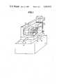
- FIG. 1is a schematic perspective view of a travelling wire EDM apparatus according to the invention
- FIG. 2is a section through the rear wall of the machining fluid tank thereof.
- FIG. 3is a section along line 3--3 of FIG. 2.
- the travelling wire EDM apparatus of the inventioncomprises a base 1 having an upright member 2 provided with a pair of electrode wire guiding arms 3 and 4.
- An electrode wire 5is supplied from a spool 6 and, after passage over rollers 7 and 8, the electrode wire 5 is wound around a receiving spool 9.
- An electrode workpiece 10is attached to supports 11 and 12 mounted in the interior of the tank 13 which is filled with a machining fluid.
- the tank 13is formed integral on the top of a cross-slide table 18 enabling the electrode workpiece 10 to be displaced relative to the wire 5 along two orthogonal directions arbitrarily represented by arrows 16 and 17.
- the cross-slide table 18is driven by a pair of servo motors 14 and 15 under the control of a numerical control unit, not shown.
- the rear wall of the tank 13is formed of two panels 19 and 20 disposed parallel to each other and provided with an opening 21 through which project the lower guiding arm 4.
- a pair of flexible seals, 27 and 28 respectively,are affixed to both faces of the plate 23 such as to form a dam in the space between each face of the plate 23 and the corresponding surfaces of the panels 19 and 20.
- the plate 23is further provided with a pair of support prongs 32 and 33, FIG. 3, in sliding engagement with the bottom 34 of the tank 13 and three guiding and spacer members 35 maintaining the plate 23 in spaced relationship relative to the panels 19 and 20.
- the tank 13is provided below the plate 23 and the panel 20 with a gutter 36 for catching any fluid leaking through the annular seals 25 and 26 and the flexible seals 27 and 28.
- a return line 37returns the machining fluid that may leak past the sealing structure 22 into the gutter 36 to the interior of the tank 13 by means of a pump, not shown.
- both wire guiding armscould be provided with a sealing joint through the machining fluid tank in structure wherein the wire is travelling horizontally within the machining fluid tank.
Landscapes
- Engineering & Computer Science (AREA)
- Mechanical Engineering (AREA)
- Chemical & Material Sciences (AREA)
- Chemical Kinetics & Catalysis (AREA)
- Electrochemistry (AREA)
- Electrical Discharge Machining, Electrochemical Machining, And Combined Machining (AREA)
Abstract
Description
Claims (5)
Applications Claiming Priority (2)
| Application Number | Priority Date | Filing Date | Title |
|---|---|---|---|
| CH4112/83ACH654777A5 (en) | 1983-07-27 | 1983-07-27 | MACHINE FOR CUTTING BY ELECTRO-EROSION. |
| CH4112/83 | 1983-07-27 |
Publications (1)
| Publication Number | Publication Date |
|---|---|
| US4565915Atrue US4565915A (en) | 1986-01-21 |
Family
ID=4270033
Family Applications (1)
| Application Number | Title | Priority Date | Filing Date |
|---|---|---|---|
| US06/631,449Expired - LifetimeUS4565915A (en) | 1983-07-27 | 1984-07-16 | Travelling wire EDM apparatus provided with a wire support arm passed through the wall of a machining fluid tank |
Country Status (5)
| Country | Link |
|---|---|
| US (1) | US4565915A (en) |
| EP (1) | EP0133160B1 (en) |
| JP (1) | JPS6052223A (en) |
| CH (1) | CH654777A5 (en) |
| DE (1) | DE3463463D1 (en) |
Cited By (25)
| Publication number | Priority date | Publication date | Assignee | Title |
|---|---|---|---|---|
| US4647747A (en)* | 1984-02-29 | 1987-03-03 | Brother Kogyo Kabushiki Kaisha | Arm extending through a work pan of a wire EDM permitting improved arm movement |
| US4675825A (en)* | 1984-10-30 | 1987-06-23 | Dementhon Daniel F | Computer-controlled peripheral shaping system |
| DE3632347A1 (en)* | 1986-09-24 | 1988-03-31 | Schiess Ag Geschaeftsbereich S | MACHINE TOOL, ESPECIALLY SPARK EDM MACHINE |
| US4808787A (en)* | 1986-11-17 | 1989-02-28 | Institute Of Technology Precision Electrical Discharge Works | Wire-cut electrical discharge machining equipment |
| US4808786A (en)* | 1986-10-07 | 1989-02-28 | Mitsubishi Denki Kabushiki Kaisha | Wire electrode type electric discharge machining device with preventable application of external force to its lower arm |
| US4918279A (en)* | 1987-08-28 | 1990-04-17 | Charmilles Technologies, S.A. | EDM cutting machine including device for preventing transmission of sealing plate movement to guide head arm |
| DE3934638A1 (en)* | 1988-10-17 | 1990-04-26 | Mitsubishi Electric Corp | SEAL ASSEMBLY FOR USE IN AN ELECTRIC EDM MACHINING DEVICE WITH A WIRE ELECTRODE |
| EP0410493A1 (en)* | 1989-07-28 | 1991-01-30 | Charmilles Technologies S.A. | Wire-cut spark erosion machine with a fixed machining table |
| US4992640A (en)* | 1989-01-27 | 1991-02-12 | Mitsubishi Denki Kabushiki Kaisha | Wire electric discharge machining apparatus |
| DE4019662A1 (en)* | 1990-06-20 | 1992-01-09 | Agie Ag Ind Elektronik | MACHINE FOR SPARK-EDM CUTTING WITH A GUIDE ARM THROUGH THE BACK OF THE WORKING LIQUID CONTAINER |
| US5196666A (en)* | 1990-10-03 | 1993-03-23 | Sodick Co., Ltd. | Arm sealing device for an edm machine |
| US5374795A (en)* | 1992-01-18 | 1994-12-20 | Fanuc | Wire cut electric discharge machine |
| US5401931A (en)* | 1992-08-13 | 1995-03-28 | Sodick Co., Ltd. | Wire-cut electroerosion apparatus |
| US5607269A (en)* | 1995-11-21 | 1997-03-04 | Osteotech, Inc. | Bone milling apparatus |
| US5780801A (en)* | 1996-05-06 | 1998-07-14 | Ona Electro-Erosion, S.A. | Semi-watertight structure for sealing plate of an immersion wire electric discharge machine |
| US6073935A (en)* | 1998-03-17 | 2000-06-13 | Ona Electro-Erosion, S.A. | Leaktight seal device for lower arm of a spark erosion machine or electrical discharge machining (EDM) device |
| ES2155319A1 (en)* | 1998-02-11 | 2001-05-01 | Ona Electro Erosion | Arm seal for wire electric discharge machining apparatus |
| US6429395B1 (en)* | 2000-01-13 | 2002-08-06 | Yu-Hwa Wei | Leakproof device of wire cut machine |
| US6524037B2 (en)* | 1999-12-13 | 2003-02-25 | Renault Automation Comau | Protection device for the driving and guiding means of a mobile element of a machine tool against projections of cuttings |
| US6583376B2 (en)* | 2000-03-30 | 2003-06-24 | Brother Kogyo Kabushiki Kaisha | Sealing apparatus used in a wire cut electric discharge machine |
| US6651987B1 (en) | 1999-10-12 | 2003-11-25 | Sodick Co., Ltd. | Seal for preventing leakage of fluid from opening formed in side wall of work tank of wire cut electric discharge machine |
| US20060237915A1 (en)* | 2005-04-25 | 2006-10-26 | Fanuc Ltd | Seal structure for a wire-cut electric discharge machine |
| US20090010731A1 (en)* | 2007-06-30 | 2009-01-08 | Trumpf Werkzeugmaschinen Gmbh + Co. Kg | Workpiece part discharge system |
| US20090194511A1 (en)* | 2008-02-01 | 2009-08-06 | Industrial Technology Research Institute | Wire electrical discharge machining |
| US20130043218A1 (en)* | 2011-08-19 | 2013-02-21 | Apple Inc. | Multi-wire cutting for efficient magnet machining |
Families Citing this family (6)
| Publication number | Priority date | Publication date | Assignee | Title |
|---|---|---|---|---|
| JP2637453B2 (en)* | 1988-02-10 | 1997-08-06 | 株式会社アマダ | Wire cut electric discharge machine |
| US5017408A (en)* | 1990-08-08 | 1991-05-21 | Eastman Kodak Company | Curtain coating start/finish method and apparatus |
| JPH0796167B2 (en)* | 1990-10-20 | 1995-10-18 | 株式会社牧野フライス製作所 | Sealing device for wire electric discharge machine |
| DE69129124T2 (en)* | 1990-10-26 | 1998-08-27 | Sodick Co Ltd | Spark erosive wire cutting device |
| CN103752968B (en)* | 2014-01-27 | 2016-04-06 | 东莞台一盈拓科技股份有限公司 | A kind of oil groove hermatic door panel assembly for large-scale spark-erosion machine tool |
| CN112809113A (en)* | 2021-01-04 | 2021-05-18 | 张晓民 | Mounting method of acoustic emission sensor |
Citations (11)
| Publication number | Priority date | Publication date | Assignee | Title |
|---|---|---|---|---|
| US2182246A (en)* | 1938-03-29 | 1939-12-05 | Tanner E Boyer | Packing gland mounting |
| US2969248A (en)* | 1957-04-19 | 1961-01-24 | Nat Gypsum Co | Shaft seal |
| US3039779A (en)* | 1959-04-30 | 1962-06-19 | Union Carbide Corp | Shaft seal |
| US3179423A (en)* | 1962-10-26 | 1965-04-20 | Ite Circuit Breaker Ltd | Gas seal for oil circuit breakers |
| US4123645A (en)* | 1976-02-25 | 1978-10-31 | Fujitsu Fanuc Limited | Numerically controlled wire-cutting electric discharge machine |
| JPS55108734A (en)* | 1979-02-14 | 1980-08-21 | Toshiba Corp | Movable table device |
| US4229010A (en)* | 1978-12-20 | 1980-10-21 | Bellofram Corporation | Self-aligning shaft seal |
| US4270775A (en)* | 1977-09-21 | 1981-06-02 | A/S Akers Mek. Versted | Device for sealing the place of penetration of a pipeline in the wall of a submerged structure |
| US4337385A (en)* | 1977-05-11 | 1982-06-29 | Uti Corporation | Orbital tool support system for EDM machines and other machine tools |
| US4460816A (en)* | 1982-07-06 | 1984-07-17 | Ateliers Des Charmilles, S.A. | Apparatus for orienting the wire electrode support and guide member and the machining fluid nozzle of a travelling wire EDM apparatus |
| US4485288A (en)* | 1982-01-04 | 1984-11-27 | Erowa Ag | Wire guiding device for electroerosion finishing machines |
Family Cites Families (1)
| Publication number | Priority date | Publication date | Assignee | Title |
|---|---|---|---|---|
| CH333268A (en)* | 1955-10-05 | 1958-10-15 | F Maschbau Ag | Device on machine tools for processing workpieces in a liquid bath, in particular for removing electrically conductive materials by spark erosion |
- 1983
- 1983-07-27CHCH4112/83Apatent/CH654777A5/ennot_activeIP Right Cessation
- 1984
- 1984-07-02EPEP84810329Apatent/EP0133160B1/ennot_activeExpired
- 1984-07-02DEDE8484810329Tpatent/DE3463463D1/ennot_activeExpired
- 1984-07-16USUS06/631,449patent/US4565915A/ennot_activeExpired - Lifetime
- 1984-07-26JPJP59156475Apatent/JPS6052223A/enactiveGranted
Patent Citations (11)
| Publication number | Priority date | Publication date | Assignee | Title |
|---|---|---|---|---|
| US2182246A (en)* | 1938-03-29 | 1939-12-05 | Tanner E Boyer | Packing gland mounting |
| US2969248A (en)* | 1957-04-19 | 1961-01-24 | Nat Gypsum Co | Shaft seal |
| US3039779A (en)* | 1959-04-30 | 1962-06-19 | Union Carbide Corp | Shaft seal |
| US3179423A (en)* | 1962-10-26 | 1965-04-20 | Ite Circuit Breaker Ltd | Gas seal for oil circuit breakers |
| US4123645A (en)* | 1976-02-25 | 1978-10-31 | Fujitsu Fanuc Limited | Numerically controlled wire-cutting electric discharge machine |
| US4337385A (en)* | 1977-05-11 | 1982-06-29 | Uti Corporation | Orbital tool support system for EDM machines and other machine tools |
| US4270775A (en)* | 1977-09-21 | 1981-06-02 | A/S Akers Mek. Versted | Device for sealing the place of penetration of a pipeline in the wall of a submerged structure |
| US4229010A (en)* | 1978-12-20 | 1980-10-21 | Bellofram Corporation | Self-aligning shaft seal |
| JPS55108734A (en)* | 1979-02-14 | 1980-08-21 | Toshiba Corp | Movable table device |
| US4485288A (en)* | 1982-01-04 | 1984-11-27 | Erowa Ag | Wire guiding device for electroerosion finishing machines |
| US4460816A (en)* | 1982-07-06 | 1984-07-17 | Ateliers Des Charmilles, S.A. | Apparatus for orienting the wire electrode support and guide member and the machining fluid nozzle of a travelling wire EDM apparatus |
Cited By (34)
| Publication number | Priority date | Publication date | Assignee | Title |
|---|---|---|---|---|
| US4647747A (en)* | 1984-02-29 | 1987-03-03 | Brother Kogyo Kabushiki Kaisha | Arm extending through a work pan of a wire EDM permitting improved arm movement |
| US4675825A (en)* | 1984-10-30 | 1987-06-23 | Dementhon Daniel F | Computer-controlled peripheral shaping system |
| DE3632347A1 (en)* | 1986-09-24 | 1988-03-31 | Schiess Ag Geschaeftsbereich S | MACHINE TOOL, ESPECIALLY SPARK EDM MACHINE |
| US4808786A (en)* | 1986-10-07 | 1989-02-28 | Mitsubishi Denki Kabushiki Kaisha | Wire electrode type electric discharge machining device with preventable application of external force to its lower arm |
| US4808787A (en)* | 1986-11-17 | 1989-02-28 | Institute Of Technology Precision Electrical Discharge Works | Wire-cut electrical discharge machining equipment |
| US4918279A (en)* | 1987-08-28 | 1990-04-17 | Charmilles Technologies, S.A. | EDM cutting machine including device for preventing transmission of sealing plate movement to guide head arm |
| US5028757A (en)* | 1988-10-17 | 1991-07-02 | Mitsubishi Denki K.K. | Sealing structure for use in wire cut electric discharge machining apparatus |
| DE3934638A1 (en)* | 1988-10-17 | 1990-04-26 | Mitsubishi Electric Corp | SEAL ASSEMBLY FOR USE IN AN ELECTRIC EDM MACHINING DEVICE WITH A WIRE ELECTRODE |
| DE3934638C3 (en)* | 1988-10-17 | 1998-11-12 | Mitsubishi Electric Corp | Sealing arrangement for use in a spark erosion machining device with a wire electrode |
| US4992640A (en)* | 1989-01-27 | 1991-02-12 | Mitsubishi Denki Kabushiki Kaisha | Wire electric discharge machining apparatus |
| DE3925009A1 (en)* | 1989-07-28 | 1991-01-31 | Schiess Ag Geschaeftsbereich S | WIRE CUTTING SPARK EDM MACHINE WITH FIXED MACHINE TABLE |
| EP0410493A1 (en)* | 1989-07-28 | 1991-01-30 | Charmilles Technologies S.A. | Wire-cut spark erosion machine with a fixed machining table |
| DE4019662A1 (en)* | 1990-06-20 | 1992-01-09 | Agie Ag Ind Elektronik | MACHINE FOR SPARK-EDM CUTTING WITH A GUIDE ARM THROUGH THE BACK OF THE WORKING LIQUID CONTAINER |
| US5111016A (en)* | 1990-06-20 | 1992-05-05 | Agie Ag Fur Industrielle Elektronik | Machine for spark erosion cutting with a guide-arm crossing the back wall of the working liquid container |
| US5196666A (en)* | 1990-10-03 | 1993-03-23 | Sodick Co., Ltd. | Arm sealing device for an edm machine |
| US5374795A (en)* | 1992-01-18 | 1994-12-20 | Fanuc | Wire cut electric discharge machine |
| US5401931A (en)* | 1992-08-13 | 1995-03-28 | Sodick Co., Ltd. | Wire-cut electroerosion apparatus |
| US5607269A (en)* | 1995-11-21 | 1997-03-04 | Osteotech, Inc. | Bone milling apparatus |
| US5780801A (en)* | 1996-05-06 | 1998-07-14 | Ona Electro-Erosion, S.A. | Semi-watertight structure for sealing plate of an immersion wire electric discharge machine |
| DE19629298C2 (en)* | 1996-05-06 | 2001-12-20 | Ona Electro Erosion | Sealed bushing for electrical erosion machines |
| ES2155319A1 (en)* | 1998-02-11 | 2001-05-01 | Ona Electro Erosion | Arm seal for wire electric discharge machining apparatus |
| US6073935A (en)* | 1998-03-17 | 2000-06-13 | Ona Electro-Erosion, S.A. | Leaktight seal device for lower arm of a spark erosion machine or electrical discharge machining (EDM) device |
| US6651987B1 (en) | 1999-10-12 | 2003-11-25 | Sodick Co., Ltd. | Seal for preventing leakage of fluid from opening formed in side wall of work tank of wire cut electric discharge machine |
| US6524037B2 (en)* | 1999-12-13 | 2003-02-25 | Renault Automation Comau | Protection device for the driving and guiding means of a mobile element of a machine tool against projections of cuttings |
| US6429395B1 (en)* | 2000-01-13 | 2002-08-06 | Yu-Hwa Wei | Leakproof device of wire cut machine |
| US6583376B2 (en)* | 2000-03-30 | 2003-06-24 | Brother Kogyo Kabushiki Kaisha | Sealing apparatus used in a wire cut electric discharge machine |
| US20060237915A1 (en)* | 2005-04-25 | 2006-10-26 | Fanuc Ltd | Seal structure for a wire-cut electric discharge machine |
| CN100429029C (en)* | 2005-04-25 | 2008-10-29 | 发那科株式会社 | Sealing Structure of Wire Cutting Machine |
| US7687739B2 (en)* | 2005-04-25 | 2010-03-30 | Fanuc Ltd | Seal structure for a wire-cut electric discharge machine |
| US20090010731A1 (en)* | 2007-06-30 | 2009-01-08 | Trumpf Werkzeugmaschinen Gmbh + Co. Kg | Workpiece part discharge system |
| US8618433B2 (en)* | 2007-06-30 | 2013-12-31 | Trumpf Werkzeugmaschinen Gmbh + Co. Kg | Workpiece part discharge system |
| US20090194511A1 (en)* | 2008-02-01 | 2009-08-06 | Industrial Technology Research Institute | Wire electrical discharge machining |
| US7973260B2 (en)* | 2008-02-01 | 2011-07-05 | Industrial Technology Research Institute | Wire electrical discharge machining |
| US20130043218A1 (en)* | 2011-08-19 | 2013-02-21 | Apple Inc. | Multi-wire cutting for efficient magnet machining |
Also Published As
| Publication number | Publication date |
|---|---|
| JPS6052223A (en) | 1985-03-25 |
| EP0133160A3 (en) | 1985-03-13 |
| CH654777A5 (en) | 1986-03-14 |
| JPH0341288B2 (en) | 1991-06-21 |
| EP0133160A2 (en) | 1985-02-13 |
| EP0133160B1 (en) | 1987-05-06 |
| DE3463463D1 (en) | 1987-06-11 |
Similar Documents
| Publication | Publication Date | Title |
|---|---|---|
| US4565915A (en) | Travelling wire EDM apparatus provided with a wire support arm passed through the wall of a machining fluid tank | |
| KR890003483A (en) | Cutting machine by electric discharge machining | |
| SE7903818L (en) | MACHINE FOR RESISTANCE ROOM WELDING | |
| IT8467670A1 (en) | System for the help of an operator in spreading flexible material such as fabric on the table of an automatic cutting machine. | |
| DE69115520D1 (en) | Working fluid circuit with line pressure control for the active suspension system of a vehicle | |
| JPS60186319A (en) | Wire-cut electrical discharge machine | |
| EP0779124B1 (en) | Wire electric discharge machine | |
| KR0163439B1 (en) | A machine for spark erosion cutting with a guide arm crossing the back wall of the working liquid container | |
| PH16482A (en) | Seal system for a turbomachine employing working fluid in its liquid phase as the sealing fluid | |
| EP0610974B1 (en) | A wire-cut electroerosion apparatus | |
| EP0186793B2 (en) | Electroerosion machine with a fixed machining table and collapsible working tank | |
| US6651987B1 (en) | Seal for preventing leakage of fluid from opening formed in side wall of work tank of wire cut electric discharge machine | |
| JPH04304927A (en) | Wire electric discharge machine | |
| US5401931A (en) | Wire-cut electroerosion apparatus | |
| US3508986A (en) | Method of sonically welded channel plates | |
| IT1084749B (en) | PROCEDURE AND DEVICE FOR FINDING AND FOLLOWING THE AUTOMATIC WELDING CORD IN NON-DESTRUCTIVE CONTROL WITH ULTRASONIC WELDED TUBES | |
| JP3319923B2 (en) | General-purpose cleaning equipment for air conditioners | |
| JPH0796167B2 (en) | Sealing device for wire electric discharge machine | |
| JP2651746B2 (en) | Immersion processing wire cut electric discharge machine | |
| CN214640594U (en) | Cutting device is used in gate valve production | |
| JPH0735709Y2 (en) | Wire electric discharge machine | |
| JP2650755B2 (en) | Wire cut electric discharge machine | |
| JP2555357B2 (en) | Wire lower support device in wire electric discharge machine | |
| JPH071241A (en) | Electric discharge machine | |
| CN217750084U (en) | Fire-fighting pipeline tee joint welding positioning device |
Legal Events
| Date | Code | Title | Description |
|---|---|---|---|
| AS | Assignment | Owner name:CHARMILLES TECHNOLOGIES SA., 109 RUE DE LYON, 1211 Free format text:ASSIGNMENT OF ASSIGNORS INTEREST.;ASSIGNOR:GIRARDIN, ROGER;REEL/FRAME:004287/0733 Effective date:19840607 Owner name:CHARMILLES TECHNOLOGIES SA., SWITZERLAND Free format text:ASSIGNMENT OF ASSIGNORS INTEREST;ASSIGNOR:GIRARDIN, ROGER;REEL/FRAME:004287/0733 Effective date:19840607 | |
| STCF | Information on status: patent grant | Free format text:PATENTED CASE | |
| FPAY | Fee payment | Year of fee payment:4 | |
| FEPP | Fee payment procedure | Free format text:PAYOR NUMBER ASSIGNED (ORIGINAL EVENT CODE: ASPN); ENTITY STATUS OF PATENT OWNER: LARGE ENTITY | |
| REFU | Refund | Free format text:REFUND OF EXCESS PAYMENTS PROCESSED (ORIGINAL EVENT CODE: R169); ENTITY STATUS OF PATENT OWNER: LARGE ENTITY | |
| FPAY | Fee payment | Year of fee payment:8 | |
| FEPP | Fee payment procedure | Free format text:PAYOR NUMBER ASSIGNED (ORIGINAL EVENT CODE: ASPN); ENTITY STATUS OF PATENT OWNER: LARGE ENTITY Free format text:PAYER NUMBER DE-ASSIGNED (ORIGINAL EVENT CODE: RMPN); ENTITY STATUS OF PATENT OWNER: LARGE ENTITY | |
| FPAY | Fee payment | Year of fee payment:12 |