US4565910A - Switch apparatus responsive to distortion - Google Patents
Switch apparatus responsive to distortionDownload PDFInfo
- Publication number
- US4565910A US4565910AUS06/673,118US67311884AUS4565910AUS 4565910 AUS4565910 AUS 4565910AUS 67311884 AUS67311884 AUS 67311884AUS 4565910 AUS4565910 AUS 4565910A
- Authority
- US
- United States
- Prior art keywords
- base member
- conductive
- cover members
- patient
- cutout
- Prior art date
- Legal status (The legal status is an assumption and is not a legal conclusion. Google has not performed a legal analysis and makes no representation as to the accuracy of the status listed.)
- Expired - Lifetime
Links
- 239000000463materialSubstances0.000claimsabstractdescription17
- 239000004020conductorSubstances0.000claimsabstractdescription15
- 238000005452bendingMethods0.000claimsabstractdescription3
- 239000003973paintSubstances0.000claimsdescription3
- 229920003023plasticPolymers0.000abstractdescription15
- 239000004033plasticSubstances0.000abstractdescription15
- 230000000474nursing effectEffects0.000abstractdescription3
- 238000010276constructionMethods0.000description6
- 239000000853adhesiveSubstances0.000description4
- 230000001070adhesive effectEffects0.000description4
- 239000006260foamSubstances0.000description3
- 239000011888foilSubstances0.000description3
- 229920001903high density polyethylenePolymers0.000description3
- 239000004700high-density polyethyleneSubstances0.000description3
- 238000004519manufacturing processMethods0.000description3
- 238000005096rolling processMethods0.000description3
- 238000007789sealingMethods0.000description3
- 229910052751metalInorganic materials0.000description2
- 239000002184metalSubstances0.000description2
- 238000012544monitoring processMethods0.000description2
- 230000002093peripheral effectEffects0.000description2
- 238000005507sprayingMethods0.000description2
- ATJFFYVFTNAWJD-UHFFFAOYSA-NTinChemical compound[Sn]ATJFFYVFTNAWJD-UHFFFAOYSA-N0.000description1
- 208000027418Wounds and injuryDiseases0.000description1
- 229910052782aluminiumInorganic materials0.000description1
- XAGFODPZIPBFFR-UHFFFAOYSA-NaluminiumChemical compound[Al]XAGFODPZIPBFFR-UHFFFAOYSA-N0.000description1
- 210000000988bone and boneAnatomy0.000description1
- 230000006378damageEffects0.000description1
- 239000003814drugSubstances0.000description1
- 229940079593drugDrugs0.000description1
- 230000000694effectsEffects0.000description1
- 208000014674injuryDiseases0.000description1
- 238000012806monitoring deviceMethods0.000description1
- 239000012811non-conductive materialSubstances0.000description1
- 238000002360preparation methodMethods0.000description1
Images

Classifications
- G—PHYSICS
- G08—SIGNALLING
- G08B—SIGNALLING OR CALLING SYSTEMS; ORDER TELEGRAPHS; ALARM SYSTEMS
- G08B21/00—Alarms responsive to a single specified undesired or abnormal condition and not otherwise provided for
- G08B21/18—Status alarms
- G08B21/22—Status alarms responsive to presence or absence of persons
Definitions
- the present inventionprovides an improved switch apparatus for this purpose and particularly one which is economical to construct, easy to use, and is more dependable than previously known types of switching devices.
- the switch apparatusincludes an elongated, thin, generally rectangular base member of insulating flexible material such as high-density polyethylene foam.
- the base portionis preferably about 1/16 inch thick and 31/2 to 5 inches wide and about 25 to 40 inches long.
- Formed in the base memberis a generally rectangular cut out opening which is preferably about 13/4 to 21/4 inches wide and of a length of about 11/2 to 2 inches less than the length of the base member.
- first and second generally rectangular, thin, electrically conductive memberthere is secured on opposite faces of the base member a first and second generally rectangular, thin, electrically conductive member.
- the electrically conductive membersmay be such as foil or foil backed with plastic, or metallized plastic material. These are secured to the base member such as by adhesive.
- the base memberthereby supports the conductive elements normally spaced apart from each other about 1/16 of an inch.
- a cable having two conductorsis provided, a conductor being connected to each of the conductive members.
- plastic cover membersOver this assembly is positioned plastic cover members which are slightly longer and wider than the base member and the conductive elements so that the cover members may be sealed along the peripheral edges, thereby completely sealing the apparatus.
- the conductive elementsare bonded to the cover members and are held in spaced apart relationship at the opening formed in the base member as long as the apparatus is not subject to weight or distortion. It can be positioned under a patient and, more particularly, under sheets, bedding or the like positioned on top of a mattress.
- the deviceneed not come into contact with the patient. When the device is placed on a bed which receives a patient, the weight of the patient will distort the apparatus, causing the conductive elements to contact each other. As long as the patient remains in the bed, the weight of the patient will cause a closed signal to be provided which, when connected to proper electrical circuits, provides an indication of the presence of a patient in the bed. When the patient evacuates the bed, the normal rigidity of the device is sufficient to cause the conductive elements to separate from each other, providing an open circuit which can be employed to indicate the absence of the patient from the bed.
- conductive surfacesare formed directly on the cover members. More particularly, a conductive surface is formed on the bottom surface of the upper cover member and another conductive layer is formed on the top surface of the lower cover member.
- These conductive layersmay be applied in a variety of ways including rolling or spraying conductive ink, paint or other material directly on the plastic cover members. Depending upon the type of material used, the conductive layers may be sprayed onto the cover members using one, two or more passes depending upon the nature of the material and the thickness of the conductive layer which is required to insure full and complete conductivity of the entire strip.
- the conductive materialis sometimes referred to as a conductive flexible ink or paint and the expression "painted on” includes rolling, spraying or any other means of applying a non-rigid material to the cover sheets to attain a flexible conductive layer.
- the cable conductorsare connected to the conductive layers.
- the second embodimentfunctions as does the first embodiment and is different substantially only in the use of conductive layers of material rather than separate conductive elements.
- the switchfunctions to provide a closed circuit when it is bent or distorted in any way. Bending may be an arcuate bend as when it is more or less uniformly curved by the weight of the patient in a bed or the switch may function to close when it is twisted or otherwise distorted.
- the switchdoes not require direct pressure to deform one of the cover members with its conductive layer to contact the conductive layer of the other cover member; that is, the switch functions by deformation rather than depending upon directly applied pressure.
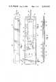
- FIG. 1is a top plan view of a switch for monitoring patient presence in a hospital bed.
- FIG. 2is a fragmentary plan view of the switch broken away, to show the internal construction.
- FIG. 3is a cross-sectional view taken along the line 3--3 of FIG. 2 showing more details of the construction of the apparatus.
- FIG. 4is a top plan view of an improved embodiment of the invention.
- FIG. 5is a fragmentary plan view improved embodiment, enlarged, which shows more details of the switch construction.
- FIG. 6is a cross-sectional view taken along the lines 6--6 of FIG. 5 showing additional details of the construction of the switch.
- the apparatus for monitoring patient presence in a hospital bedis indicated generally by the numeral 10. It includes a base member 12 which is formed of non-electrically conductive, flexible, thin material.
- An ideal material for use in practicing the inventionis high-density polyethylene foam.
- the base member 12is of generally rectangular configuration having opposed sides 14 and 16 and ends 18 and 20.
- Formed in the base memberis a cutout opening 22 which is generally rectangular and of dimensions about 11/2 to 21/2 inches less in width and length than the base member itself. In the typical embodiment of the invention the base member length, from end 18 to end 20, is about 25 to 40 inches long.
- the width from sides 14 to 16is preferably about 33/4 to 5 inches.
- the thickness of the base memberis preferably about 1/16 inch.
- the opening 22is preferably about 13/4 to 21/4 inches wide and about 221/2 to 381/2 inches long, depending on the width and length of the base member.
- the base member 12can be described as generally rectangular, and the opening cutout 22 can likewise be described as generally rectangular. However, both may have curved corners if desired.
- the conductive members 28 and 34are preferably of thin metal, such as tin foil, aluminum foil or the like, or of metal surfaces bonded to a plastic backing core, or are of metalized plastic. The dimensions of the conductive members 28 and 34 are substantially equal to or slightly less than that of the base member 12.
- the base member opening 22causes the conductive members 28 and 34 to be supported in spaced-apart relationship.
- a top plastic cover member 36has one surface 38 in engagement with of the first conductive member 28.
- a bottom cover member 40engages the second surface 42 of the second conductive member 34.
- the cover members 36 and 40are slightly larger in both length and width than that of base member 12 so that they provide an overlapping peripheral edge 44 around the entire apparatus.
- the end 18 of base member 12has a notch 28 formed in it which receives the end portion of a cable 48.
- the notchmay extend at an angle to the end 18 of the base member 50 so that the conductor emerges at or near edge 14 or 16.
- the cablehas a first current carrying conductor 50 which is positioned to contact the first conductive member 28.
- a second conductor 52contacts the second conductive element 34. This may be achieved by merely exposing the conductive portions 50 and 52 of the cable 48 to contact the surfaces of the conductive members as the conductive members are secured to the base member.
- the apparatusis constructed in this manner. First, the base member 12 is provided with the dimensions as previously set out and with the notch 46 formed in it. An adhesive is applied to the top and bottom surfaces of the base member. Next, the cable 48 is positioned with the end in notch 46 and with conductors 50 and 52 exposed on opposed surfaces of the base member. The conductive members 28 and 34 are then positioned on the base member. The conductive members 28 and 34 thereby engage the conductors 50 and 52 respectively. Next, the cover members 36 and 40 are positioned over the conductive members with adhesive therebetween. The assembly is then pressed securely together by means of a press or rollers to bond the portions to each other. The edge 44 is sealed around the complete assembly. The switch is then completed.
- the switchcan be expeditiously assembled. This is important in that the device can be considered a throw-away item, that is, it can be limited in usage to one patient. Others may elect to sanitize the device for reuse, which can be easily accomplished since it is hermetically sealed and only the exterior surfaces of the cover are exposed.
- the construction of the devicemeans that when no pressure or distorton takes place it is self-rigid so that no contact is provided between the conductive members 28 and 34. However, with the weight of a patient on the device, distortion is sufficient to cause the conductive members 28 and 34 to contact at one place or another, or at a plurality of places along the length of the device, providing a closed circuit.
- FIGS. 4, 5 and 6an alternate embodiment of the invention is shown which is considered to be an improvement over the embodiment of FIGS. 1, 2 and 3 in that the cost of manufacture is reduced and the accuracy and dependability of the switch is advanced.
- the letter 10arefers to the alternate embodiment and as seen in FIG. 1 the external appearance, ignoring the dotted lines indicating internal arrangements, of the alternate embodiment is the same as that of the first described embodiment.
- a base member 12which is formed of non-electrically conductive, flexible, thin material, such as high-density polyethylene foam.
- the base 12is of generally rectangular configuration and has opposed sides 14 and 16 and ends 18 and 20.
- a cutout opening 22is formed in a base member and has dimensions as described with reference to the first embodiment.
- Base member 12has a top surface 24 and a bottom surface 30. Encompassing the base member is a first nonconductive, thin generally rectangular upper cover member 36 and a similar lower cover member 40.
- Upper cover member 36has a bottom surface 36A and a top surface 36B which forms the top exterior surface of the switch.
- lower cover member 40has a top surface 40A and a bottom surface 40B, the bottom surface forming the exterior bottom of the switch.
- a first electrically conductive layer 54Formed on the bottom surface 36A of top cover 36 is a first electrically conductive layer 54 and in like manner formed on the top surface 40A of the lower cover 40 is a conductive layer 56.
- the conductive layers 54 and 56run the full length of the upper and lower covers 36 and 40.
- the width of the conductive layers 54 and 56is preferably about that of cutout 22 in the base portion 12. As shown in FIGS. 5 and 6 the width of the conductive layers is somewhat less than that of the cutout 22 although the width could be greater than the width of the cutout.
- the conductive layers 54 and 56are formed of conductive ink which may be applied by rolling the ink onto the upper and lower plastic covers 36 and 40 or the ink may be sprayed onto the material which is used to form the covers. If sprayed, more than one layer of conductive ink may be sprayed on. Since the conductive layer may be sprayed, rolled or brushed on it may be generally described as being "painted" onto one surface of each of the upper and lower cover members.
- the switchincludes a cable 48 with conductors 50 and 52 which are secured to the conductive layers 54 and 56, respectively.
- the switchis completed by sealing the edges of the cover members beyond the periphery of the base member 12. These may be sealed or bonded such as by the use of adhesives or by heat sealing.
- a conductive layermay be applied the full length of an elongated strip of plastic material and the strip then cut in lengths to form the upper cover 36 and lower cover 40.
- some meansmust be provided to prevent the conductive layers from contacting each other at the ends 58 and 60 of the switch. This can be accomplished by inserting small pieces 62 and 64 of thin, non-conductive material between the upper and lower covers 36 and 40 before the edges are sealed or bonded to each other.
- These thin, non-conductive pieces 62 and 64may be of plastic material which is heat fused or chemically bonded to the cover portions 36 and 40.
- FIGS. 4, 5, and 6employs the "painted on" conductive layers 36 and 40 in place of conductive members 28 and 34 of the first embodiment and otherwise the switch functions in the same way as in the first described embodiment.
- the weight of a patient lying or sitting on the bedwill distort the switch and thereby cause the conductive layers 36 and 40 to contact each other. This is so whether or not the patient's weight is directly on the switch or not.
- the switchwill be distorted so as to provide a closed electrical circuit.
- the decrease in the distortion of the switchwill cause the switch to open and such change in circuitry can be employed to provide a signal that the patient is about to or has exited from the bed.
Landscapes
- Business, Economics & Management (AREA)
- Emergency Management (AREA)
- Physics & Mathematics (AREA)
- General Physics & Mathematics (AREA)
- Push-Button Switches (AREA)
- Measuring And Recording Apparatus For Diagnosis (AREA)
Abstract
Description
Claims (3)
Priority Applications (1)
| Application Number | Priority Date | Filing Date | Title |
|---|---|---|---|
| US06/673,118US4565910A (en) | 1982-09-30 | 1984-11-19 | Switch apparatus responsive to distortion |
Applications Claiming Priority (2)
| Application Number | Priority Date | Filing Date | Title |
|---|---|---|---|
| US06/429,047US4484043A (en) | 1982-09-30 | 1982-09-30 | Switch apparatus responsive to pressure or distortion |
| US06/673,118US4565910A (en) | 1982-09-30 | 1984-11-19 | Switch apparatus responsive to distortion |
Related Parent Applications (1)
| Application Number | Title | Priority Date | Filing Date |
|---|---|---|---|
| US06/429,047Continuation-In-PartUS4484043A (en) | 1982-09-30 | 1982-09-30 | Switch apparatus responsive to pressure or distortion |
Publications (1)
| Publication Number | Publication Date |
|---|---|
| US4565910Atrue US4565910A (en) | 1986-01-21 |
Family
ID=27028011
Family Applications (1)
| Application Number | Title | Priority Date | Filing Date |
|---|---|---|---|
| US06/673,118Expired - LifetimeUS4565910A (en) | 1982-09-30 | 1984-11-19 | Switch apparatus responsive to distortion |
Country Status (1)
| Country | Link |
|---|---|
| US (1) | US4565910A (en) |
Cited By (60)
| Publication number | Priority date | Publication date | Assignee | Title |
|---|---|---|---|---|
| US4845323A (en)* | 1987-08-28 | 1989-07-04 | Tactilitics, Inc. | Flexible tactile switch |
| US4947298A (en)* | 1989-08-21 | 1990-08-07 | Stephen John L | Bed lighting apparatus |
| US5068504A (en)* | 1989-03-15 | 1991-11-26 | Rogers John E | Seat cushions and body supports, and fitting instruments for the same |
| US5148911A (en)* | 1991-10-31 | 1992-09-22 | Miller Edge, Inc. | Sensing edge switch |
| US5353012A (en)* | 1992-05-14 | 1994-10-04 | Bartronix, Inc. | Bed position and activity sensing apparatus |
| US5471198A (en)* | 1994-11-22 | 1995-11-28 | Newham; Paul | Device for monitoring the presence of a person using a reflective energy beam |
| US5554835A (en)* | 1994-07-27 | 1996-09-10 | Bed-Check Corporation | Traversing conductor pressure sensitive switch |
| US5600108A (en)* | 1994-08-29 | 1997-02-04 | Bed-Check Corporation | Docking module enclosure including connectors and power switching |
| US5633627A (en)* | 1994-09-23 | 1997-05-27 | Bed-Check Corporation | Hard-wired monitoring system for hospital bed or short term care patients |
| WO1997020294A1 (en)* | 1994-11-22 | 1997-06-05 | Paul Newham | Device for monitoring the presence of a person using a reflective energy beam |
| US5640145A (en)* | 1994-10-11 | 1997-06-17 | Bed-Check Corporation | Remote controlled system for monitoring the occupancy of an infant bearing device |
| US5647265A (en)* | 1993-06-30 | 1997-07-15 | The United States Of America As Represented By The Secretary Of The Navy | Tool and system for machining a round strand |
| US5654694A (en)* | 1994-09-23 | 1997-08-05 | Bed-Check Corporation | Mobile battery powered patient bed and chair occupancy monitoring system |
| WO1998010391A1 (en)* | 1996-09-04 | 1998-03-12 | Paul Newham | Device for monitoring the presence of a person using proximity induced dielectric shift sensing |
| WO1998018318A1 (en)* | 1996-10-29 | 1998-05-07 | Rentokil Initial U.K. Limited | Rodent detection apparatus |
| US5945914A (en)* | 1998-06-11 | 1999-08-31 | Bed-Check Corporation | Toilet seat occupancy monitoring apparatus |
| WO1999044180A1 (en)* | 1998-02-26 | 1999-09-02 | Bed-Check Corporation | Microprocessor based bed patient monitor |
| US6078261A (en)* | 1998-11-10 | 2000-06-20 | Alert Systems, Inc. | System for monitoring a bed patient |
| US6165142A (en)* | 1998-09-21 | 2000-12-26 | Roho, Inc. | Biomedical apparatus |
| US6180893B1 (en) | 1999-03-03 | 2001-01-30 | Peter Salgo | Patient weighing apparatus |
| US6204767B1 (en) | 1999-06-04 | 2001-03-20 | Donald A. Edwards | Chair monitor |
| US6307168B1 (en) | 1999-03-23 | 2001-10-23 | Paul Newham | Linear spaced dielectric dot separator pressure sensing array incorporating strain release stabilized releasable electric snap stud connectors |
| US6307476B1 (en) | 1999-04-02 | 2001-10-23 | Bed-Check Corporation | Smart binary switch for use with an electronic patient monitor |
| US6417777B2 (en) | 2000-02-23 | 2002-07-09 | Bed-Check Corporation | Pressure sensitive mat with breathing tube apparatus |
| US6545236B2 (en) | 2001-02-07 | 2003-04-08 | Lear Corporation | Vehicle interior component having a flexible cover with integrated circuitry |
| US6611783B2 (en) | 2000-01-07 | 2003-08-26 | Nocwatch, Inc. | Attitude indicator and activity monitoring device |
| US20030197614A1 (en)* | 2002-04-18 | 2003-10-23 | Bed-Check Corporation | Apparatus for lighting a patient monitor front panel |
| US6696653B1 (en) | 2001-06-07 | 2004-02-24 | Bed-Check Corporation | Binary switch apparatus and method for manufacturing same |
| US20040046668A1 (en)* | 2000-06-09 | 2004-03-11 | Bed-Check Corporation | Apparatus and method for reducing the risk of decubitus ulcers |
| US6778090B2 (en) | 1996-09-04 | 2004-08-17 | Paul Newham | Modular system for monitoring the presence of a person using a variety of sensing devices |
| US6784797B2 (en) | 1998-02-26 | 2004-08-31 | Bed-Check Corporation | Microprocessor based bed patient monitor |
| US6788206B1 (en) | 2002-09-05 | 2004-09-07 | Donald A. Edwards | Patient monitoring system |
| US6791460B2 (en) | 1999-03-05 | 2004-09-14 | Hill-Rom Services, Inc. | Patient position detection apparatus for a bed |
| US20040183681A1 (en)* | 2003-03-18 | 2004-09-23 | Bed-Check Corporation | Power latch for use with an electronic patient monitor |
| US6858811B2 (en)* | 2001-06-07 | 2005-02-22 | Bed-Check Corporation | Binary switch apparatus and method for manufacturing same |
| US20050046575A1 (en)* | 2003-08-20 | 2005-03-03 | Bed-Check Corporation | Method and apparatus for alarm volume control using pulse width modulation |
| US20050082466A1 (en)* | 2003-10-17 | 2005-04-21 | Bed-Check Corporation | Displacement sensor apparatus |
| US20050083207A1 (en)* | 2003-10-17 | 2005-04-21 | Bed-Check Corporation | Method and apparatus for monitoring a restraint device |
| US20050172398A1 (en)* | 2004-02-11 | 2005-08-11 | Bed-Check Corporation | Feedback control system to reduce the risk of pressure sores |
| US20060028350A1 (en)* | 2004-08-09 | 2006-02-09 | Bhai Aziz A | Apparatus and method for monitoring a patient in a hospital bed |
| US20070040692A1 (en)* | 2005-08-19 | 2007-02-22 | Bed-Check Corporation | Method and apparatus for temporarily disabling a patient monitor |
| US7378975B1 (en) | 2000-06-09 | 2008-05-27 | Bed-Check Corporation | Method and apparatus for mitigating the risk of pressure sores |
| US20100039269A1 (en)* | 2008-08-13 | 2010-02-18 | Paul Newham | Modular Systems for Monitoring the Presence of a Person Using a Variety of Sensing Devices |
| US20100057543A1 (en)* | 2005-05-19 | 2010-03-04 | Barton Dring | System and methods for monitoring caregiver performance |
| US20100073168A1 (en)* | 2008-09-19 | 2010-03-25 | Tallent Dan R | System and Method for Reporting Status of a Bed |
| US20100245090A1 (en)* | 2004-05-19 | 2010-09-30 | Bed-Check Corporation | Patient thermal monitoring system |
| US7821415B1 (en) | 2008-04-04 | 2010-10-26 | Kimberlin Denver K | Pneumatically operated patient bed monitor |
| US7834768B2 (en) | 1999-03-05 | 2010-11-16 | Hill-Rom Services, Inc. | Obstruction detection apparatus for a bed |
| US20110061164A1 (en)* | 2009-09-11 | 2011-03-17 | Genaro David M | Bed Exit Alarm |
| US8344860B2 (en) | 2004-08-02 | 2013-01-01 | Hill-Rom Services, Inc. | Patient support apparatus alert system |
| US8432287B2 (en) | 2010-07-30 | 2013-04-30 | Hill-Rom Services, Inc. | Apparatus for controlling room lighting in response to bed exit |
| US8464380B2 (en) | 2005-07-08 | 2013-06-18 | Hill-Rom Services, Inc. | Patient support apparatus having alert light |
| US8717181B2 (en) | 2010-07-29 | 2014-05-06 | Hill-Rom Services, Inc. | Bed exit alert silence with automatic re-enable |
| US20160063846A1 (en)* | 2014-08-27 | 2016-03-03 | Umano Medical Inc. | Hospital bed with patient weight and displacement sensors |
| USD751044S1 (en)* | 2014-05-22 | 2016-03-08 | Hzo, Inc. | Control switch for an electronic device |
| US9655798B2 (en) | 2013-03-14 | 2017-05-23 | Hill-Rom Services, Inc. | Multi-alert lights for hospital bed |
| US10206836B2 (en) | 2011-11-11 | 2019-02-19 | Hill-Rom Services, Inc. | Bed exit alerts for person support apparatus |
| US10231890B2 (en) | 2014-06-06 | 2019-03-19 | Kinetic Medical Aid Innovations, Inc. | Apparatus for reducing the risk of developing decubitus ulcers and adjunct to treatment thereof on immobile patients |
| US10292605B2 (en) | 2012-11-15 | 2019-05-21 | Hill-Rom Services, Inc. | Bed load cell based physiological sensing systems and methods |
| US10504353B2 (en) | 2015-07-27 | 2019-12-10 | Hill-Rom Services, Inc. | Customized bed exit warnings to modify patient behavior |
Citations (4)
| Publication number | Priority date | Publication date | Assignee | Title |
|---|---|---|---|---|
| US3860771A (en)* | 1973-10-29 | 1975-01-14 | Chomerics Inc | Keyboard switch assembly with dome shaped actuator having associated underlying contactor means |
| US4194099A (en)* | 1977-10-25 | 1980-03-18 | W. H. Brady Co. | Control panel overlay |
| US4237358A (en)* | 1979-05-07 | 1980-12-02 | Oak Industries Inc. | Isolation membrane switch |
| US4484043A (en)* | 1982-09-30 | 1984-11-20 | Bed-Check Corporation | Switch apparatus responsive to pressure or distortion |
- 1984
- 1984-11-19USUS06/673,118patent/US4565910A/ennot_activeExpired - Lifetime
Patent Citations (4)
| Publication number | Priority date | Publication date | Assignee | Title |
|---|---|---|---|---|
| US3860771A (en)* | 1973-10-29 | 1975-01-14 | Chomerics Inc | Keyboard switch assembly with dome shaped actuator having associated underlying contactor means |
| US4194099A (en)* | 1977-10-25 | 1980-03-18 | W. H. Brady Co. | Control panel overlay |
| US4237358A (en)* | 1979-05-07 | 1980-12-02 | Oak Industries Inc. | Isolation membrane switch |
| US4484043A (en)* | 1982-09-30 | 1984-11-20 | Bed-Check Corporation | Switch apparatus responsive to pressure or distortion |
Cited By (107)
| Publication number | Priority date | Publication date | Assignee | Title |
|---|---|---|---|---|
| US4845323A (en)* | 1987-08-28 | 1989-07-04 | Tactilitics, Inc. | Flexible tactile switch |
| US5068504A (en)* | 1989-03-15 | 1991-11-26 | Rogers John E | Seat cushions and body supports, and fitting instruments for the same |
| US4947298A (en)* | 1989-08-21 | 1990-08-07 | Stephen John L | Bed lighting apparatus |
| US5148911A (en)* | 1991-10-31 | 1992-09-22 | Miller Edge, Inc. | Sensing edge switch |
| US5353012A (en)* | 1992-05-14 | 1994-10-04 | Bartronix, Inc. | Bed position and activity sensing apparatus |
| US5647265A (en)* | 1993-06-30 | 1997-07-15 | The United States Of America As Represented By The Secretary Of The Navy | Tool and system for machining a round strand |
| US5554835A (en)* | 1994-07-27 | 1996-09-10 | Bed-Check Corporation | Traversing conductor pressure sensitive switch |
| US5623760A (en)* | 1994-07-27 | 1997-04-29 | Bed-Check Corporation | Pressure sensitive switch |
| US5600108A (en)* | 1994-08-29 | 1997-02-04 | Bed-Check Corporation | Docking module enclosure including connectors and power switching |
| US5633627A (en)* | 1994-09-23 | 1997-05-27 | Bed-Check Corporation | Hard-wired monitoring system for hospital bed or short term care patients |
| US5654694A (en)* | 1994-09-23 | 1997-08-05 | Bed-Check Corporation | Mobile battery powered patient bed and chair occupancy monitoring system |
| US5640145A (en)* | 1994-10-11 | 1997-06-17 | Bed-Check Corporation | Remote controlled system for monitoring the occupancy of an infant bearing device |
| WO1997020294A1 (en)* | 1994-11-22 | 1997-06-05 | Paul Newham | Device for monitoring the presence of a person using a reflective energy beam |
| US5471198A (en)* | 1994-11-22 | 1995-11-28 | Newham; Paul | Device for monitoring the presence of a person using a reflective energy beam |
| WO1998010391A1 (en)* | 1996-09-04 | 1998-03-12 | Paul Newham | Device for monitoring the presence of a person using proximity induced dielectric shift sensing |
| US6778090B2 (en) | 1996-09-04 | 2004-08-17 | Paul Newham | Modular system for monitoring the presence of a person using a variety of sensing devices |
| GB2332063A (en)* | 1996-09-04 | 1999-06-09 | Paul F Newham | Device for monitoring the presence of a person using proximity induced dielectric shift sensing |
| US6025782A (en)* | 1996-09-04 | 2000-02-15 | Newham; Paul | Device for monitoring the presence of a person using proximity induced dielectric shift sensing |
| GB2332063B (en)* | 1996-09-04 | 2000-11-01 | Paul F Newham | Device for monitoring the presence of a person using proximity induced dielectric shift sensing |
| US6297738B1 (en) | 1996-09-04 | 2001-10-02 | Paul Newham | Modular system for monitoring the presence of a person using a variety of sensing devices |
| WO1998018318A1 (en)* | 1996-10-29 | 1998-05-07 | Rentokil Initial U.K. Limited | Rodent detection apparatus |
| WO1999044180A1 (en)* | 1998-02-26 | 1999-09-02 | Bed-Check Corporation | Microprocessor based bed patient monitor |
| US6784797B2 (en) | 1998-02-26 | 2004-08-31 | Bed-Check Corporation | Microprocessor based bed patient monitor |
| US6111509A (en)* | 1998-02-26 | 2000-08-29 | Bed-Check Corporation | Microprocessor based bed patient monitor |
| US5945914A (en)* | 1998-06-11 | 1999-08-31 | Bed-Check Corporation | Toilet seat occupancy monitoring apparatus |
| WO1999063876A1 (en) | 1998-06-11 | 1999-12-16 | Bed-Check Corporation | Toilet seat occupancy monitoring apparatus |
| US6165142A (en)* | 1998-09-21 | 2000-12-26 | Roho, Inc. | Biomedical apparatus |
| US6078261A (en)* | 1998-11-10 | 2000-06-20 | Alert Systems, Inc. | System for monitoring a bed patient |
| US6180893B1 (en) | 1999-03-03 | 2001-01-30 | Peter Salgo | Patient weighing apparatus |
| US8830070B2 (en) | 1999-03-05 | 2014-09-09 | Hill-Rom Services, Inc. | Hospital bed having alert light |
| US20080010747A1 (en)* | 1999-03-05 | 2008-01-17 | Dixon Stephen A | Electrical Connector Assembly Suitable for a Bed Footboard |
| US7834768B2 (en) | 1999-03-05 | 2010-11-16 | Hill-Rom Services, Inc. | Obstruction detection apparatus for a bed |
| US20110037597A1 (en)* | 1999-03-05 | 2011-02-17 | Dixon Stephen A | Body position monitoring system |
| US7978084B2 (en) | 1999-03-05 | 2011-07-12 | Hill-Rom Services, Inc. | Body position monitoring system |
| US7986242B2 (en) | 1999-03-05 | 2011-07-26 | Hill-Rom Services, Inc. | Electrical connector assembly suitable for a bed footboard |
| US8258963B2 (en) | 1999-03-05 | 2012-09-04 | Hill-Rom Services, Inc. | Body position monitoring system |
| US20050166324A1 (en)* | 1999-03-05 | 2005-08-04 | Dixon Stephen A. | Romovable footboard for a hospital bed |
| US8400311B2 (en) | 1999-03-05 | 2013-03-19 | Hill-Rom Services, Inc. | Hospital bed having alert light |
| US6791460B2 (en) | 1999-03-05 | 2004-09-14 | Hill-Rom Services, Inc. | Patient position detection apparatus for a bed |
| US8525682B2 (en) | 1999-03-05 | 2013-09-03 | Hill-Rom Services, Inc. | Hospital bed having alert light |
| US20050035871A1 (en)* | 1999-03-05 | 2005-02-17 | Hill-Rom Services, Inc. | Patient position detection apparatus for a bed |
| US6307168B1 (en) | 1999-03-23 | 2001-10-23 | Paul Newham | Linear spaced dielectric dot separator pressure sensing array incorporating strain release stabilized releasable electric snap stud connectors |
| US6307476B1 (en) | 1999-04-02 | 2001-10-23 | Bed-Check Corporation | Smart binary switch for use with an electronic patient monitor |
| US6204767B1 (en) | 1999-06-04 | 2001-03-20 | Donald A. Edwards | Chair monitor |
| US6611783B2 (en) | 2000-01-07 | 2003-08-26 | Nocwatch, Inc. | Attitude indicator and activity monitoring device |
| US6417777B2 (en) | 2000-02-23 | 2002-07-09 | Bed-Check Corporation | Pressure sensitive mat with breathing tube apparatus |
| US7030764B2 (en) | 2000-06-09 | 2006-04-18 | Bed-Check Corporation | Apparatus and method for reducing the risk of decubitus ulcers |
| US7378975B1 (en) | 2000-06-09 | 2008-05-27 | Bed-Check Corporation | Method and apparatus for mitigating the risk of pressure sores |
| US20040046668A1 (en)* | 2000-06-09 | 2004-03-11 | Bed-Check Corporation | Apparatus and method for reducing the risk of decubitus ulcers |
| US6545236B2 (en) | 2001-02-07 | 2003-04-08 | Lear Corporation | Vehicle interior component having a flexible cover with integrated circuitry |
| US6696653B1 (en) | 2001-06-07 | 2004-02-24 | Bed-Check Corporation | Binary switch apparatus and method for manufacturing same |
| US6858811B2 (en)* | 2001-06-07 | 2005-02-22 | Bed-Check Corporation | Binary switch apparatus and method for manufacturing same |
| US20030197614A1 (en)* | 2002-04-18 | 2003-10-23 | Bed-Check Corporation | Apparatus for lighting a patient monitor front panel |
| US6864795B2 (en) | 2002-04-18 | 2005-03-08 | Bed-Check Corporation | Apparatus for lighting a patient monitor front panel |
| US6788206B1 (en) | 2002-09-05 | 2004-09-07 | Donald A. Edwards | Patient monitoring system |
| US6998986B2 (en) | 2003-03-18 | 2006-02-14 | Bed-Check Corporation | Power latch for use with an electronic patient monitor |
| US20040183681A1 (en)* | 2003-03-18 | 2004-09-23 | Bed-Check Corporation | Power latch for use with an electronic patient monitor |
| US7079036B2 (en) | 2003-08-20 | 2006-07-18 | Bed-Check Corporation | Method and apparatus for alarm volume control using pulse width modulation |
| US20050046575A1 (en)* | 2003-08-20 | 2005-03-03 | Bed-Check Corporation | Method and apparatus for alarm volume control using pulse width modulation |
| US7319400B2 (en) | 2003-10-17 | 2008-01-15 | Bed-Check Corporation | Method and apparatus for monitoring a restraint device |
| US20050082466A1 (en)* | 2003-10-17 | 2005-04-21 | Bed-Check Corporation | Displacement sensor apparatus |
| US20050083207A1 (en)* | 2003-10-17 | 2005-04-21 | Bed-Check Corporation | Method and apparatus for monitoring a restraint device |
| US7078676B2 (en) | 2003-10-17 | 2006-07-18 | Bed-Check Corporation | Displacement sensor apparatus |
| US20050172398A1 (en)* | 2004-02-11 | 2005-08-11 | Bed-Check Corporation | Feedback control system to reduce the risk of pressure sores |
| US20100245090A1 (en)* | 2004-05-19 | 2010-09-30 | Bed-Check Corporation | Patient thermal monitoring system |
| US8344860B2 (en) | 2004-08-02 | 2013-01-01 | Hill-Rom Services, Inc. | Patient support apparatus alert system |
| US20070268147A1 (en)* | 2004-08-09 | 2007-11-22 | Hill-Rom Services, Inc. | Load-cell based hospital bed control |
| US7437787B2 (en) | 2004-08-09 | 2008-10-21 | Hill-Rom Services, Inc. | Load-cell based hospital bed control |
| US20060028350A1 (en)* | 2004-08-09 | 2006-02-09 | Bhai Aziz A | Apparatus and method for monitoring a patient in a hospital bed |
| US7253366B2 (en) | 2004-08-09 | 2007-08-07 | Hill-Rom Services, Inc. | Exit alarm for a hospital bed triggered by individual load cell weight readings exceeding a predetermined threshold |
| US8564445B2 (en) | 2005-05-19 | 2013-10-22 | Proacticare Llc | System and methods for monitoring caregiver performance |
| US8154413B2 (en)* | 2005-05-19 | 2012-04-10 | Proacticare Llc | System and methods for monitoring caregiver performance |
| US20100057543A1 (en)* | 2005-05-19 | 2010-03-04 | Barton Dring | System and methods for monitoring caregiver performance |
| US8464380B2 (en) | 2005-07-08 | 2013-06-18 | Hill-Rom Services, Inc. | Patient support apparatus having alert light |
| US9220650B2 (en) | 2005-07-08 | 2015-12-29 | Hill-Rom Services, Inc. | Patient support apparatus having alert light |
| US10561550B2 (en) | 2005-07-08 | 2020-02-18 | Hill-Rom Services, Inc. | Patient support apparatus having alert light |
| US20070040692A1 (en)* | 2005-08-19 | 2007-02-22 | Bed-Check Corporation | Method and apparatus for temporarily disabling a patient monitor |
| US7570152B2 (en) | 2005-08-19 | 2009-08-04 | Bed-Check Corporation | Method and apparatus for temporarily disabling a patient monitor |
| US7821415B1 (en) | 2008-04-04 | 2010-10-26 | Kimberlin Denver K | Pneumatically operated patient bed monitor |
| US7940187B2 (en) | 2008-08-13 | 2011-05-10 | Paul Newham | Modular systems for monitoring the presence of a person using a variety of sensing devices |
| US20100039269A1 (en)* | 2008-08-13 | 2010-02-18 | Paul Newham | Modular Systems for Monitoring the Presence of a Person Using a Variety of Sensing Devices |
| US8537008B2 (en) | 2008-09-19 | 2013-09-17 | Hill-Rom Services, Inc. | Bed status indicators |
| US8593284B2 (en) | 2008-09-19 | 2013-11-26 | Hill-Rom Services, Inc. | System and method for reporting status of a bed |
| US8847756B2 (en) | 2008-09-19 | 2014-09-30 | Hill-Rom Services, Inc. | Bed status indicators |
| US20100073168A1 (en)* | 2008-09-19 | 2010-03-25 | Tallent Dan R | System and Method for Reporting Status of a Bed |
| US8042206B2 (en) | 2009-09-11 | 2011-10-25 | Anodyne Medical Device, Inc. | Bed exit alarm |
| US20110061164A1 (en)* | 2009-09-11 | 2011-03-17 | Genaro David M | Bed Exit Alarm |
| US8717181B2 (en) | 2010-07-29 | 2014-05-06 | Hill-Rom Services, Inc. | Bed exit alert silence with automatic re-enable |
| US8432287B2 (en) | 2010-07-30 | 2013-04-30 | Hill-Rom Services, Inc. | Apparatus for controlling room lighting in response to bed exit |
| US10206836B2 (en) | 2011-11-11 | 2019-02-19 | Hill-Rom Services, Inc. | Bed exit alerts for person support apparatus |
| US10292605B2 (en) | 2012-11-15 | 2019-05-21 | Hill-Rom Services, Inc. | Bed load cell based physiological sensing systems and methods |
| US9655798B2 (en) | 2013-03-14 | 2017-05-23 | Hill-Rom Services, Inc. | Multi-alert lights for hospital bed |
| US11833090B2 (en) | 2013-03-14 | 2023-12-05 | Hill-Rom Services, Inc. | Multi-alert lights for hospital bed |
| US11464692B2 (en) | 2013-03-14 | 2022-10-11 | Hill-Rom Services, Inc. | Multi-alert lights for hospital bed |
| US10709625B2 (en) | 2013-03-14 | 2020-07-14 | Hill-Rom Services, Inc. | Foot end alert display for hospital bed |
| US10413465B2 (en) | 2013-03-14 | 2019-09-17 | Hill-Rom Services, Inc. | Multi-alert lights for hospital bed |
| US10918546B2 (en) | 2013-03-14 | 2021-02-16 | Hill-Rom Services, Inc. | Multi-alert lights for hospital bed |
| US10512574B2 (en) | 2013-03-14 | 2019-12-24 | Hill-Rom Services, Inc. | Multi-alert lights for hospital bed |
| US12186249B2 (en) | 2013-03-14 | 2025-01-07 | Hill-Rom Services, Inc. | Multi-alert lights for hospital bed |
| USD751044S1 (en)* | 2014-05-22 | 2016-03-08 | Hzo, Inc. | Control switch for an electronic device |
| US10231890B2 (en) | 2014-06-06 | 2019-03-19 | Kinetic Medical Aid Innovations, Inc. | Apparatus for reducing the risk of developing decubitus ulcers and adjunct to treatment thereof on immobile patients |
| US9987182B2 (en) | 2014-08-27 | 2018-06-05 | Umano Medical Inc. | Hospital bed with patient weight and displacement sensors for determining at least one of lateral and longitudinal patient location on a patient support assembly |
| US10117798B2 (en) | 2014-08-27 | 2018-11-06 | Umano Medical Inc. | Hospital bed with patient weight and displacement sensors |
| US9754476B2 (en)* | 2014-08-27 | 2017-09-05 | Umano Medical Inc. | Hospital bed with patient weight and displacement sensors |
| US20160063846A1 (en)* | 2014-08-27 | 2016-03-03 | Umano Medical Inc. | Hospital bed with patient weight and displacement sensors |
| US10504353B2 (en) | 2015-07-27 | 2019-12-10 | Hill-Rom Services, Inc. | Customized bed exit warnings to modify patient behavior |
| US11282365B2 (en) | 2015-07-27 | 2022-03-22 | Hill-Rom Services, Inc. | Customized bed exit warnings to modify patient behavior |
Similar Documents
| Publication | Publication Date | Title |
|---|---|---|
| US4565910A (en) | Switch apparatus responsive to distortion | |
| US4484043A (en) | Switch apparatus responsive to pressure or distortion | |
| US4845323A (en) | Flexible tactile switch | |
| US4172216A (en) | Pressure sensitive switch | |
| EP0107058B1 (en) | Apparatus for monitoring the presence of a person in a bed | |
| US3778570A (en) | Enuresis bed pad | |
| US2668202A (en) | Moisture responsive signaling device | |
| CN105553323B (en) | Physiological monitoring sensing belt and manufacturing method thereof, physiological monitoring mattress and monitoring system | |
| US3944763A (en) | Swimming pool touch pad | |
| GB2166871A (en) | Respiration monitor | |
| US6696653B1 (en) | Binary switch apparatus and method for manufacturing same | |
| US3518984A (en) | Packaged diagnostic electrode device | |
| KR101784736B1 (en) | Sensor using PVDF film | |
| US6727445B2 (en) | Sensor pads for patient monitoring devices | |
| CA1279887C (en) | Tape element and methods, for heating, pressure measurement and circuit fabrication | |
| US5168875A (en) | Elongated strip electrode arrangement and method | |
| EP0121544A1 (en) | Device for measuring the presence of electrical conducting liquid received therein | |
| US4037069A (en) | Mat switch | |
| JP3334234B2 (en) | Diaper change sensor | |
| US4382246A (en) | Apparatus for measuring temperature | |
| JPH09103414A (en) | Electrode to detect especially electric biological signal which is electrocardiogram signal | |
| US8798709B1 (en) | Dermal sensing package and use | |
| DE69731849D1 (en) | ELECTROLYSIS DEVICE WITH LIQUID THROTTLE UNIT WITHOUT CONTACT WITH THE TAPE | |
| WO2003052368A1 (en) | Sensor mat for registering a pressure profile | |
| GB2464965A (en) | Presence Detector |
Legal Events
| Date | Code | Title | Description |
|---|---|---|---|
| AS | Assignment | Owner name:BED-CHECK CORPORATION TULSA OKLAHOMA A CORP OF OKL Free format text:ASSIGNMENT OF ASSIGNORS INTEREST.;ASSIGNORS:MUSICK, JEFF L.;BLAKER, ROBERT D.;BLAKER, DAVID G.;REEL/FRAME:004337/0340 Effective date:19841119 Owner name:BED-CHECK CORPORATION,OKLAHOMA Free format text:ASSIGNMENT OF ASSIGNORS INTEREST;ASSIGNORS:MUSICK, JEFF L.;BLAKER, ROBERT D.;BLAKER, DAVID G.;REEL/FRAME:004337/0340 Effective date:19841119 | |
| STCF | Information on status: patent grant | Free format text:PATENTED CASE | |
| FEPP | Fee payment procedure | Free format text:PAYOR NUMBER ASSIGNED (ORIGINAL EVENT CODE: ASPN); ENTITY STATUS OF PATENT OWNER: LARGE ENTITY | |
| FPAY | Fee payment | Year of fee payment:4 | |
| FPAY | Fee payment | Year of fee payment:8 | |
| FEPP | Fee payment procedure | Free format text:PAYER NUMBER DE-ASSIGNED (ORIGINAL EVENT CODE: RMPN); ENTITY STATUS OF PATENT OWNER: LARGE ENTITY Free format text:PAYOR NUMBER ASSIGNED (ORIGINAL EVENT CODE: ASPN); ENTITY STATUS OF PATENT OWNER: LARGE ENTITY | |
| FPAY | Fee payment | Year of fee payment:12 | |
| AS | Assignment | Owner name:J. T. POSEY COMPANY, CALIFORNIA Free format text:SETTLEMENT AGREEMENT AFFECTING PATENT RIGHTS;ASSIGNOR:BED-CHECK CORPORATION;REEL/FRAME:013974/0402 Effective date:20030115 | |
| FEPP | Fee payment procedure | Free format text:PAT HOLDER NO LONGER CLAIMS SMALL ENTITY STATUS, ENTITY STATUS SET TO UNDISCOUNTED (ORIGINAL EVENT CODE: STOL); ENTITY STATUS OF PATENT OWNER: LARGE ENTITY |