US4564320A - Form broach assembly - Google Patents
Form broach assemblyDownload PDFInfo
- Publication number
- US4564320A US4564320AUS06/575,498US57549884AUS4564320AUS 4564320 AUS4564320 AUS 4564320AUS 57549884 AUS57549884 AUS 57549884AUS 4564320 AUS4564320 AUS 4564320A
- Authority
- US
- United States
- Prior art keywords
- tooth
- teeth
- block
- recess
- hold
- Prior art date
- Legal status (The legal status is an assumption and is not a legal conclusion. Google has not performed a legal analysis and makes no representation as to the accuracy of the status listed.)
- Expired - Fee Related
Links
Images


Classifications
- B—PERFORMING OPERATIONS; TRANSPORTING
- B23—MACHINE TOOLS; METAL-WORKING NOT OTHERWISE PROVIDED FOR
- B23D—PLANING; SLOTTING; SHEARING; BROACHING; SAWING; FILING; SCRAPING; LIKE OPERATIONS FOR WORKING METAL BY REMOVING MATERIAL, NOT OTHERWISE PROVIDED FOR
- B23D43/00—Broaching tools
- B23D43/02—Broaching tools for cutting by rectilinear movement
- B23D43/04—Broaching tools for cutting by rectilinear movement having inserted cutting edges
- Y—GENERAL TAGGING OF NEW TECHNOLOGICAL DEVELOPMENTS; GENERAL TAGGING OF CROSS-SECTIONAL TECHNOLOGIES SPANNING OVER SEVERAL SECTIONS OF THE IPC; TECHNICAL SUBJECTS COVERED BY FORMER USPC CROSS-REFERENCE ART COLLECTIONS [XRACs] AND DIGESTS
- Y10—TECHNICAL SUBJECTS COVERED BY FORMER USPC
- Y10T—TECHNICAL SUBJECTS COVERED BY FORMER US CLASSIFICATION
- Y10T407/00—Cutters, for shaping
- Y10T407/16—Rectilinear broach
- Y10T407/1628—Rectilinear broach including holder having seat for inserted tool
- Y10T407/1657—Rectilinear broach including holder having seat for inserted tool including single tooth
Definitions
- a tool assembly with multiple teeth for form broaching of metal partsis provided.
- Form broaching and particularly slot broachinghas been accomplished in the prior art with one-piece tooling in which individual teeth are ground into the tooling. Because of the limitations on the size of grinding wheels, it has been extremely difficult and costly to approximate the desired true form relief on the teeth of the tool.
- the advantage of a broaching tooth with a true relief form all the way around the toothis that the profile remains uniformly proportional when the cutter is sharpened. Furthermore, a smaller relief angle can be used due to the true form relief to allow more sharpenings before the size change exceeds part tolerances.
- the designalso allows the use of carbide as a tool material for even greater tool life. This has not been possible in the one-piece design because of the difficulty in grinding carbide with the small grinding wheels necessary to grind the relief on one tooth without hitting the cutting edge of an adjacent tooth.
- the individual cuttersmay each be made on computer numerical control (CNC) equipment to obtain the true form relief.
- CNCcomputer numerical control
- Another object and advantage of the inventionlies in the tooth retaining assembly which provides accurate positioning and alignment of the individually ground teeth in a stepped hold-down block and wedge lock which cooperate to secure the teeth in a recessed holder.
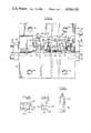
- FIG. 1a plan view of the tool assembly.
- FIG. 2a side view of the assembly depicted in FIG. 1.
- FIG. 3an end view, partially in section, on line 3--3 of FIG. 2.
- FIG. 4an end view of the assembly taken on line 4--4 of FIG. 2.
- FIG. 5an enlarged side view of a tooth partially in section showing the face angle and relief angle.
- FIG. 6a side elevation of an individual tooth taken on line 6--6 of FIG. 2.
- FIG. 7an enlarged front view of a tooth illustrating the true form relief.
- FIG. 8a sectional view on line 8--8 of FIG. 7 showing the face angle.
- FIG. 9a side elevation of a tooth hold-down block.
- FIG. 10an end view of the hold-down block depicted in FIG. 9.
- FIG. 1a plan view of the slot broach assembly shows a support base block 20 with a top recess 22 which carries a plurality of individual teeth 30 each having a cutting contour at the distal upwardly extending end and a root portion seated at one side of the recess 22 against a wall 32.
- the manner of securing the teethwill be later described.
- each following toothcut progressively more of the work part than the leading teeth.
- a profile reliefis necessary for each tooth.
- individual teethare shown with one example of a profile for a slot.
- a side view of the teethis found in FIG. 2. While the profile relief is not shown in FIG. 2, the horizontal lines on the cutting end will have, for example, a 2° back relief including the entire profile and radii in the profile.
- FIG. 5a side view of a tooth illustrates, as an example, a 2° back relief angle which is provided for the entire profiled cutting portion of the tooth.
- Each toothcan be made on a computer numerical control machine.
- the radii and the profileare true form from the front to the back of the tooth.
- There is, for an example, a 15° face angle on the cutting profile and the properly profiled toothcan be sharpened on this lead face surface without distorting the profile for subsequent cutting.
- This designalso allows the use of solid carbide as a tool material to provide even greater tool life. Grinding will ensmall the profile but leave it otherwise undistorted.
- FIG. 5As has been described, the face angle of 15° at the top of the tooth has been described and also the form relief angle or back clearance of 2°, as an example.
- FIG. 7a frontal enlarged view of a tooth T is illustrated and form relief around the entire cutting form is illustrated in the dotted line just inside the profile line of the tooth.
- a small sectional view in FIG. 8shows the 15° face angle extending inwardly from the profiled cutting edge.
- the blades 30have one straight base side 54, which may be termed a gauging side, lying flat against the wall 32.
- the bottom 55 of the tooth lying in contact with the flat base wall 52also forms a gauging surface with respect to the height of the tooth.
- the opposite side of each blade basehas a notch 56 to receive a side projection 58 on a hold-down clamp block 60.
- the block 60has a groove 62 in the face 64 and the lower face 66 of the projection 58. The purpose of this groove 62 is to insure positive seating on the surfaces 64 and 66 of adjacent blades since each holder block is designed to span two adjacent blades.
- the notch 56 in the blade and the projections 58will be dimensioned to insure tight positioning.
- Recessed holes 68are provided in each hold-down block 60 to receive standard socket head screws 70 threaded in to the base holder block.
- a wedge block 80is shown in cross-section. These blocks have a width to span two of the hold-down blocks 60 (FIG. 1) and likewise have a central face groove 82 to insure positive seating on each hold-down block 60 contacted. These wedge blocks have an angled face 84 (FIG. 3) to cooperate with an angled face 42 in the base holder block. The angle of these faces is preferably about 10°.
- Two recessed holesare provided in blocks 80 to receive socket head screws 86 threaded into base block 20.
- a slight clearanceis provided in the screw holes in the blocks 60 and 80 to allow some shifting toward the wall 32 in the base block 20.
- each adjacent pair of broach cutter teeth 30is backed by and clamped down by a hold-down block 60.
- Each pair of blocks 60is backed by a wedge block 80.
- the cuttersare seated on the base wall 52 and aligned against wall 32 in base block 20 in conjunction with the hold-down blocks 60.
- the screws 70are partially tightened.
- Wedge blocks 80are placed behind each pair of blocks 60 and screws 86 tightened to move the blocks 60 against the cutters and the cutters into tight contact with the vertical wall 32 and the base wall 52.
- the screws 70are then finally tightened. This assures that the cutters 30 are properly aligned in the base block 20.
- the base block 20has recessed holes 90 to serve in clamping the base block in an appropriate broaching position. As shown in FIGS. 1, 2 and 4, the ends of the broaching tooth slot are closed respectively by plates 92 and 94 secuted to the base block 20 by bolts 96 and 98 respectively. An end filler plate 100 is wedged into the teeth endwise by end plate 94, as shown best in FIG. 2, to pack the cutter teeth in close array before final clamping. A pair of screws 102 hold filler plate 100 in position.
- each tooth or series of teethwill have progressively differing dimensions so that, for an example, a slot being broached will be gradually enlarged to the desired dimension.
- the slotcan be broached accurately with chip relief where needed. Any particular tooth can be removed and replaced if need be and all teeth may be reground for sharpening. With the forming of true relief angles, smaller relief angles may be used and this will allow more sharpenings before the size change exceeds part tolerance.
Landscapes
- Engineering & Computer Science (AREA)
- Mechanical Engineering (AREA)
- Milling, Broaching, Filing, Reaming, And Others (AREA)
Abstract
Description
Claims (2)
Priority Applications (1)
| Application Number | Priority Date | Filing Date | Title |
|---|---|---|---|
| US06/575,498US4564320A (en) | 1984-01-23 | 1984-01-23 | Form broach assembly |
Applications Claiming Priority (1)
| Application Number | Priority Date | Filing Date | Title |
|---|---|---|---|
| US06/575,498US4564320A (en) | 1984-01-23 | 1984-01-23 | Form broach assembly |
Publications (1)
| Publication Number | Publication Date |
|---|---|
| US4564320Atrue US4564320A (en) | 1986-01-14 |
Family
ID=24300558
Family Applications (1)
| Application Number | Title | Priority Date | Filing Date |
|---|---|---|---|
| US06/575,498Expired - Fee RelatedUS4564320A (en) | 1984-01-23 | 1984-01-23 | Form broach assembly |
Country Status (1)
| Country | Link |
|---|---|
| US (1) | US4564320A (en) |
Cited By (13)
| Publication number | Priority date | Publication date | Assignee | Title |
|---|---|---|---|---|
| US5176480A (en)* | 1990-06-11 | 1993-01-05 | Carboloy Inc. | Broaching apparatus and methods |
| US6702524B2 (en) | 2001-06-04 | 2004-03-09 | Rolls-Royce Corporation | Broach carrier |
| US6767168B2 (en) | 2000-06-04 | 2004-07-27 | Rolls-Royce Corporation | Method and apparatus for forming openings in a workpiece |
| US20070065238A1 (en)* | 2005-09-16 | 2007-03-22 | Seco Tools Ab | Broach tool and a broach insert |
| US20100068400A1 (en)* | 2006-11-29 | 2010-03-18 | Peter Reimann | Composition for use as a preventive temporary fire protection agent, the application thereof to products, and the production and use of same |
| US20110023302A1 (en)* | 2009-07-31 | 2011-02-03 | Valinge Innovation Ab | Methods and arrangements relating to edge machining of building panels |
| US20110023303A1 (en)* | 2009-07-31 | 2011-02-03 | Valinge Innovation Ab | Methods and arrangements relating to edge machining of building panels |
| EP2481507A1 (en)* | 2011-02-01 | 2012-08-01 | United Technologies Corporation | Tooth for a broaching tool, broaching tool and method of manufacture of broaching tool |
| US20130008295A1 (en)* | 2006-09-28 | 2013-01-10 | Gm Global Technology Operations, Inc. | Cutting tool for forming and re-forming welding electrodes with contoured faces |
| US9816270B2 (en) | 2012-06-19 | 2017-11-14 | Valinge Innovation Ab | Mechanical locking system for floorboards |
| US10378217B2 (en) | 2002-04-03 | 2019-08-13 | Valinge Innovation Ab | Method of separating a floorboard material |
| US11680413B2 (en) | 2019-09-24 | 2023-06-20 | Valinge Innovation Ab | Building panel |
| US11717901B2 (en) | 2009-07-31 | 2023-08-08 | Valinge Innovation Ab | Methods and arrangements relating to edge machining of building panels |
Citations (4)
| Publication number | Priority date | Publication date | Assignee | Title |
|---|---|---|---|---|
| GB664315A (en)* | 1949-09-14 | 1952-01-02 | Lapointe Machine Tool Co | Improvements in or relating to surface type broach with multiple inserted cutters |
| US3512235A (en)* | 1968-01-02 | 1970-05-19 | Colonial Broach & Machine Co | Broach assembly |
| US4243347A (en)* | 1979-02-28 | 1981-01-06 | General Electric Company | Broaching assembly having disposable carbide inserts |
| US4294568A (en)* | 1977-02-05 | 1981-10-13 | Motoren- Und Turbinen-Union Munchen Gmbh | Process for broaching of grooves |
- 1984
- 1984-01-23USUS06/575,498patent/US4564320A/ennot_activeExpired - Fee Related
Patent Citations (4)
| Publication number | Priority date | Publication date | Assignee | Title |
|---|---|---|---|---|
| GB664315A (en)* | 1949-09-14 | 1952-01-02 | Lapointe Machine Tool Co | Improvements in or relating to surface type broach with multiple inserted cutters |
| US3512235A (en)* | 1968-01-02 | 1970-05-19 | Colonial Broach & Machine Co | Broach assembly |
| US4294568A (en)* | 1977-02-05 | 1981-10-13 | Motoren- Und Turbinen-Union Munchen Gmbh | Process for broaching of grooves |
| US4243347A (en)* | 1979-02-28 | 1981-01-06 | General Electric Company | Broaching assembly having disposable carbide inserts |
Cited By (26)
| Publication number | Priority date | Publication date | Assignee | Title |
|---|---|---|---|---|
| US5176480A (en)* | 1990-06-11 | 1993-01-05 | Carboloy Inc. | Broaching apparatus and methods |
| US6767168B2 (en) | 2000-06-04 | 2004-07-27 | Rolls-Royce Corporation | Method and apparatus for forming openings in a workpiece |
| US6702524B2 (en) | 2001-06-04 | 2004-03-09 | Rolls-Royce Corporation | Broach carrier |
| US10378217B2 (en) | 2002-04-03 | 2019-08-13 | Valinge Innovation Ab | Method of separating a floorboard material |
| US20070065238A1 (en)* | 2005-09-16 | 2007-03-22 | Seco Tools Ab | Broach tool and a broach insert |
| CN101262975B (en)* | 2005-09-16 | 2011-08-03 | 山高刀具公司 | Broach tool and broach insert |
| US8070396B2 (en)* | 2005-09-16 | 2011-12-06 | Seco Tools Ab | Broach tool and a broach insert |
| KR101291887B1 (en)* | 2005-09-16 | 2013-07-31 | 쎄코 툴스 에이비 | A broach tool and a broach insert |
| US20130008295A1 (en)* | 2006-09-28 | 2013-01-10 | Gm Global Technology Operations, Inc. | Cutting tool for forming and re-forming welding electrodes with contoured faces |
| US8833215B2 (en)* | 2006-09-28 | 2014-09-16 | GM Global Technology Operations LLC | Cutting tool for forming and re-forming welding electrodes with contoured faces |
| US20100068400A1 (en)* | 2006-11-29 | 2010-03-18 | Peter Reimann | Composition for use as a preventive temporary fire protection agent, the application thereof to products, and the production and use of same |
| US20110023303A1 (en)* | 2009-07-31 | 2011-02-03 | Valinge Innovation Ab | Methods and arrangements relating to edge machining of building panels |
| US10279404B2 (en)* | 2009-07-31 | 2019-05-07 | Valinge Innovation Ab | Methods and arrangements relating to edge machining of building panels |
| US11717901B2 (en) | 2009-07-31 | 2023-08-08 | Valinge Innovation Ab | Methods and arrangements relating to edge machining of building panels |
| CN102574292A (en)* | 2009-07-31 | 2012-07-11 | 瓦林格创新股份有限公司 | Methods and arrangements relating to edge machining of building panels |
| US8931174B2 (en) | 2009-07-31 | 2015-01-13 | Valinge Innovation Ab | Methods and arrangements relating to edge machining of building panels |
| US9314888B2 (en) | 2009-07-31 | 2016-04-19 | Valinge Innovation Ab | Methods and arrangements relating to edge machining of building panels |
| US10500684B2 (en) | 2009-07-31 | 2019-12-10 | Valinge Innovation Ab | Methods and arrangements relating to edge machining of building panels |
| US20110023302A1 (en)* | 2009-07-31 | 2011-02-03 | Valinge Innovation Ab | Methods and arrangements relating to edge machining of building panels |
| EP2481507A1 (en)* | 2011-02-01 | 2012-08-01 | United Technologies Corporation | Tooth for a broaching tool, broaching tool and method of manufacture of broaching tool |
| US8647022B2 (en) | 2011-02-01 | 2014-02-11 | United Technologies Corporation | Broaching tool |
| US9816270B2 (en) | 2012-06-19 | 2017-11-14 | Valinge Innovation Ab | Mechanical locking system for floorboards |
| US10697175B2 (en) | 2012-06-19 | 2020-06-30 | Valinge Innovation Ab | Mechanical locking system for floorboards |
| US11479970B2 (en) | 2012-06-19 | 2022-10-25 | Valinge Innovation Ab | Mechanical locking system for floorboards |
| US12065828B2 (en) | 2012-06-19 | 2024-08-20 | Välinge Innovation AB | Mechanical locking system for floorboards |
| US11680413B2 (en) | 2019-09-24 | 2023-06-20 | Valinge Innovation Ab | Building panel |
Similar Documents
| Publication | Publication Date | Title |
|---|---|---|
| US4564320A (en) | Form broach assembly | |
| US3694876A (en) | Indexable cutting insert and holder therefor | |
| US4443136A (en) | Machine cutting tool | |
| US3688368A (en) | Milling tools for the machining of gears | |
| US4202650A (en) | Shim lock toolholder | |
| US3656220A (en) | Indexable broach | |
| US3716900A (en) | Indexable cutting insert and holder therefor | |
| EP0143143A2 (en) | A cutting tool | |
| US3744349A (en) | Chain saw sharpener | |
| US4063841A (en) | Indexable insert for grooving tools | |
| US4861011A (en) | Workpiece receiving and positioning device for machining operations | |
| CA2531425A1 (en) | Cutting insert | |
| US3757397A (en) | Cutting tools | |
| US4585375A (en) | Milling inserts | |
| US3813746A (en) | Tool holder | |
| US3163918A (en) | Grooving tool | |
| US3180006A (en) | Grooving tool | |
| US3829943A (en) | Threading tool | |
| US3561086A (en) | Cut-off tools and slotting cutters | |
| JPS59156614A (en) | Tool shaping tooth surface | |
| US3848865A (en) | Cutting tool holding device | |
| US2831241A (en) | Broach blade holder | |
| US5205678A (en) | Gear cutting tool | |
| US3461748A (en) | Method of making a broaching tool | |
| CN210997578U (en) | Lead tooth lid and mill inclined plane frock |
Legal Events
| Date | Code | Title | Description |
|---|---|---|---|
| AS | Assignment | Owner name:MICHIGAN NATIONAL BANK- OAKLAND, A NATIONAL BANKIN Free format text:SECURITY INTEREST;ASSIGNOR:ROSELIEP, ROBERT E.;REEL/FRAME:004611/0404 Effective date:19860813 | |
| FPAY | Fee payment | Year of fee payment:4 | |
| AS | Assignment | Owner name:ACCURATE CLAMP CO. A CORPORATION OF MICHIGAN Free format text:ASSIGNMENT OF ASSIGNORS INTEREST.;ASSIGNOR:GENERAL BROACH AND ENGINEERING COMPANY, A CORP. OF MI;REEL/FRAME:005869/0804 Effective date:19910920 | |
| AS | Assignment | Owner name:GENERAL BROACH AND ENGINEERING COMPANY A CORPOR Free format text:ASSIGNMENT OF ASSIGNORS INTEREST.;ASSIGNOR:ROSELIEP, ROBERT E.;REEL/FRAME:005897/0434 Effective date:19910920 | |
| AS | Assignment | Owner name:COMERICA BANK, A MICHIGAN BANKING CORP. Free format text:SECURITY INTEREST;ASSIGNOR:ACCURATE CLAMP COMPANY A CORP. OF MI;REEL/FRAME:005919/0249 Effective date:19910920 | |
| FEPP | Fee payment procedure | Free format text:PAYOR NUMBER ASSIGNED (ORIGINAL EVENT CODE: ASPN); ENTITY STATUS OF PATENT OWNER: SMALL ENTITY | |
| AS | Assignment | Owner name:GENERAL BROACH & ENGINEERING, INC. Free format text:CHANGE OF NAME;ASSIGNOR:ACCURATE CLAMP COMPANY;REEL/FRAME:005984/0281 Effective date:19910922 Owner name:GENERAL BROACH & ENGINEERING, INC., MICHIGAN Free format text:CHANGE OF NAME;ASSIGNOR:ACCURATE CLAMP COMPANY;REEL/FRAME:005984/0281 Effective date:19910922 | |
| FPAY | Fee payment | Year of fee payment:8 | |
| REMI | Maintenance fee reminder mailed | ||
| LAPS | Lapse for failure to pay maintenance fees | ||
| FP | Lapsed due to failure to pay maintenance fee | Effective date:19980114 | |
| STCH | Information on status: patent discontinuation | Free format text:PATENT EXPIRED DUE TO NONPAYMENT OF MAINTENANCE FEES UNDER 37 CFR 1.362 |