US4563124A - Double suction, single stage volute pump - Google Patents
Double suction, single stage volute pumpDownload PDFInfo
- Publication number
- US4563124A US4563124AUS06/583,581US58358184AUS4563124AUS 4563124 AUS4563124 AUS 4563124AUS 58358184 AUS58358184 AUS 58358184AUS 4563124 AUS4563124 AUS 4563124A
- Authority
- US
- United States
- Prior art keywords
- impeller
- volute
- pump
- pair
- receiving openings
- Prior art date
- Legal status (The legal status is an assumption and is not a legal conclusion. Google has not performed a legal analysis and makes no representation as to the accuracy of the status listed.)
- Expired - Fee Related
Links
- 239000012530fluidSubstances0.000claimsdescription5
- 230000005540biological transmissionEffects0.000description13
- 238000005266castingMethods0.000description12
- 125000006850spacer groupChemical group0.000description3
- XLYOFNOQVPJJNP-UHFFFAOYSA-NwaterSubstancesOXLYOFNOQVPJJNP-UHFFFAOYSA-N0.000description3
- 239000000463materialSubstances0.000description2
- 238000010276constructionMethods0.000description1
- 238000003754machiningMethods0.000description1
- 238000009428plumbingMethods0.000description1
- 230000000717retained effectEffects0.000description1
- 238000007789sealingMethods0.000description1
Images


Classifications
- F—MECHANICAL ENGINEERING; LIGHTING; HEATING; WEAPONS; BLASTING
- F04—POSITIVE - DISPLACEMENT MACHINES FOR LIQUIDS; PUMPS FOR LIQUIDS OR ELASTIC FLUIDS
- F04D—NON-POSITIVE-DISPLACEMENT PUMPS
- F04D29/00—Details, component parts, or accessories
- F04D29/40—Casings; Connections of working fluid
- F04D29/42—Casings; Connections of working fluid for radial or helico-centrifugal pumps
- F04D29/426—Casings; Connections of working fluid for radial or helico-centrifugal pumps especially adapted for liquid pumps
- F—MECHANICAL ENGINEERING; LIGHTING; HEATING; WEAPONS; BLASTING
- F04—POSITIVE - DISPLACEMENT MACHINES FOR LIQUIDS; PUMPS FOR LIQUIDS OR ELASTIC FLUIDS
- F04D—NON-POSITIVE-DISPLACEMENT PUMPS
- F04D29/00—Details, component parts, or accessories
- F04D29/60—Mounting; Assembling; Disassembling
- F04D29/62—Mounting; Assembling; Disassembling of radial or helico-centrifugal pumps
- F04D29/628—Mounting; Assembling; Disassembling of radial or helico-centrifugal pumps especially adapted for liquid pumps
Definitions
- the present inventionrelates generally to pumps of the impeller type, and more particularly to a double suction, single stage volute pump.
- a pumpermounted upon the frame of this vehicle is a large pump which can typically receive water from either side of the vehicle, raise the pressure of the water and discharge it to either side of the vehicle.
- the pumpmay be of a single impeller design as shown in U.S. Pat. No. 3,500,961 or a multiple impeller design as shown in U.S. Pat. No. 3,726,308. Both single and multiple volute pumps have their own advantages, and the principal advantage of the single volute pump is its lower cost and simplicity of operation.
- the above objectis accomplished by providing a single piece pump casing design which is provided with a single volute defining portion having a pair of generally circular shroud receiving openings on the sides of the volute defining portion.
- the pump casinghas exterior sidewalls which are disposed on opposite sides of the volute portion, each of the sidewalls being provided with an opening for receiving a housing, the housing receiving opening being coaxial with the shroud receiving openings in the volute defining portion.
- a rotary impeller assemblywhich includes an impeller and an impeller shaft can be installed into the pump casting or casing from one side or the other, the impeller assembly passing through a housing receiving opening and a shroud receiving opening until the impeller is properly located within the volute.
- the pumpfurther includes a pair of impeller shrouds which are secured to opposed sides of the volute portion, the impeller shrouds covering at least a portion of the shroud receiving openings.
- a pair of housingsare secured to the exterior sidewalls of the pump casting, the housings in turn supporting the impeller shaft.
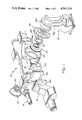
- FIG. 1is an exploded perspective view of the pump of this invention and associated components.
- FIG. 2is a cross-sectional view showing the various components in their assembled position.
- FIG. 3is a section of the pump casing taken generally along the line 3--3 in FIG. 2.
- FIGS. 4 and 5are sections taken generally along the lines 4--4 and 5--5 in FIG. 3.
- the double suction, single stage volute pump of this inventionwhich is indicated generally at 10, is adapted to be driven by a transmission disposed within a transmission housing indicated generally at 12.
- the pumpWhen in use the pump will normally be connected to the frame of a vehicle, such as a pumper, and the transmission housing may be disposed directly forwardly of the pump.
- the transmissionis in turn adapted to be interconnected with a drive shaft extending rearwardly from the vehicle engine in a manner not material to the present invention.
- the vehicleis not illustrated.
- four discharge outlets, indicated generally by the reference numeral 14are associated with the pump only one of which is shown in FIG. 1. Thus, there are two discharge outlets on each side of the pump.
- Fire hosesmay in turn be connected to the discharge outlets.
- intake manifolds 16are also provided, there being one on each side of the pump, only one being illustrated in FIG. 1.
- the intake or suction manifolds 16can be in turn connected to fire hydrants, ponds, etc. by suitable lines.
- the fluid connections 14 and 16 to the pump 10form no part of the present invention, they will not be described in further detail.
- the principal components of the pumpare a single piece pump casing 18, a rotary impeller assembly, which assembly includes an impeller 20 and an impeller shaft 22, a pair of substantially identical impeller shrouds 24, a bearing housing 26, and a seal housing 28.
- the impeller shaft 22is adapted to be rotated by means of a sprocket 30 which is secured in place by a key 32.
- the sprocket 30is in turn caused to be rotated by a chain 34 which is driven by another sprocket (not shown) in a lower portion of the transmission housing 12.
- the transmission caseis secured to the pump 10 by means of a plurality of bolts 36, only one of which is shown in FIG. 2, the bolts being received in a plurality of spaced apart threaded apertures in the seal housing 28.
- the side of the transmission opposite the bolts 36is provided with an opening 38, which opening is closed by an outboard bearing housing 40.
- the seal housing 28 and the outboard bearing housing 40are each provided with a portion capable of receiving the outer race of an associated ball bearing, the inner race of each bearing 42 being disposed about an end portion 44 of the shaft 22.
- the ball bearing within the seal housing 28is retained in place by a retaining ring 46.
- Spacers 48 and 50are spaced to either side of the sprocket 30 and function to maintain the sprocket 30 and key 32 in their assembled position.
- the outboard bearing housing 40is secured to the transmission case 12 by bolts 52. Also, a nut 54 is secued to the threaded end of the shaft 22 to hold the shaft 22, bearings 42, spacers 48, 50, and sprocket 30 in their assembled position.
- the shaft 22has a larger diameter portion 56 which is disposed generally within the seal housing 28, the shaft portions 44 and 56 forming a shoulder which abuts the inner race of the bearing 42 carried by the seal housing 28.
- the seal housingis provided with an annular groove adjacent the bearing 42 for the reception of a double lip oil seal 60 which bears against the portion 56 and serves to retain oil within the transmission case 12.
- An end face seal assembly, indicated generally at 62,is also mounted upon the larger portion 56 of the shaft 22, a portion of the seal assembly 62 being received within an annular recess in the seal housing 28.
- a gallery 64 and drain 66are provided in seal housing 28.
- the seal housingis provided with a radially outwardly extending lip portion 68 which is provided with a plurality of circumferentially spaced apart apertures which receive mounting bolts 70, the mounting bolts 70 in turn being receiving within suitable apertures in the pump casting 18.
- the exterior sidewall of the pump adjacent the transmission case 12is also provided with a cylindrical opening 72 (FIG. 1) for receiving a cylindrical portion 74 of the seal housing 28.
- the pump housingis also provided with another cylindrical opening 76, the openings 72 and 76 being formed in spaced apart sidewalls 78 and 80, respectively.
- the pump casingis also formed with a single volute 82 having a discharge 84 (FIGS. 3 and 5).
- the volute 82is formed by a generally circumferential volute defining portion 86 of the casting, the volute defining portion 86 being provided with a pair of generally circular shroud receiving openings 88, 90 (FIG. 4).
- the shrouds 24are substantially identical, each shroud having a cylindrical portion 92 (FIG.
- each of the shroudsis provided with a radially inner cylindrical recess which receives a wear ring 98.
- the impeller 20is of generally conventional construction having opposed inlet eyes 100, 102 and centrally located discharge orifices 104.
- the impelleradditionally has opposed external cylindrical portions 106 which are adapted to be received with the wear rings 98.
- the shaft 22is provided with a further reduced diameter portion 108 which forms with the larger diameter portion 56 another shoulder 110.
- An abutment portion 112 of the impeller assemblybears against the shoulder 110 and is held in place by a retaining ring 114.
- the impelleris keyed to the shaft 22 so that it will rotate with the shaft and the sprocket 30.
- the bearing housing 26is provided with a cylindrical portion 116 and a radially outwardly extending flanged portion 118 provided with a plurality of circumferentially spaced apart openings which will receive bolts 120 to secure the bearing housing in its assembled position with portion 116 within opening 76.
- the radially inner portion of the bearing housing 26is provided with a portion which receives a tapered journal bearing 122 which rotatably receives the end portion of shaft 22.
- a cover 124is secured to the bearing housing 26 by bolts 126 and serves to cover the cylindrical bore which receives the bearing 122.
- both the bearing housing 26 and the seal housing 28are each provided with a radially inwardly extending fixed vane 128, 139, respectively, which vanes assist in the operation of the pump.
- the pump castingis provided with right and left inlet passageways 132, the water flow, during operation of the impeller assembly, normally flowing in the direction indicated by the arrows 134, the inlets 132 being divided by the volute defining portion 86 to provide passageways 136.
- These passagewaysextend to the eyes 100, 102 of the impeller, and in this respect it should be noted that the shrouds 24 serve to form an extension of the passageways 136.
- the castingis provided with a flange 138 about the beginning of each of the inlets 132 and the flanged portion 140 of an intake manifold 16 can be secured thereto by suitable fasteners.
- the castingis provided with mounting pads 142.
- these pads 142can be disposed upon portions of the frame of a vehicle and secured thereto by bolts or the like.
- the discharge portion 84 of the volute 82terminates in a left hand discharge header 144.
- This headeris provided with forward and rear ports 146 and 148, respectively, which may be connected to discharge outlets in a conventional manner, such as by bolting the outlet to the face of the casting about the outlet port.
- the castingis provided with a service port 150 which is customarily closed by an access cover plate (not shown).
- the left hand discharge header 144is interconnected with a right hand discharge header 152 by a pair of generally parallel passageways 154 which are disposed to either side of the discharge portion 84.
- the casting portion which forms the right hand header 152is also provided with front and rear discharge ports 156 and 158 and a valve port 160.
- the valve port 160is customarily provided with a relief valve (not shown) which permits high pressure fluid to pass through the port 160 and return bore 162 back to inlet 132. After a valve has been assembled in to the valve port 160 the port is closed with a cover plate (not shown).
- the pump of the present designcan be serviced with greater facility than other comparable pumps. Thus, if it is necessary to service the pump, it is not necessary to disconnect any of the plumbing associated with the pump under most circumstances.
- To service the pumpthe outboard bearing housing 40 is first removed and then nut 54 and the left hand bearing 42 are removed. At this time it is desirable to remove the top half 164 of the transmission case 12, leaving the bottom half 166, in place.
- the chainis now removed from the sprocket 30, and the spacers 48 and 50 and sprocket 30 are removed from the shaft 22.
- the bearing housing 26is removably by simply unfastening the bolts 120. This provides access to the interior of the pump housing.
- the right hand impeller shroud 24is removed by unfastening the bolts 96 and the shroud is then removed permitting the removal of shaft 22 and the impeller 20.
- the impeller 20can now be serviced and the right hand wear ring 98 can also be serviced.
- If necessary to service the left hand wear ringit is first necessary to drop the lower half or bottom half of the transmission 166. Then the seal housing 28 is removed and then the left hand shroud 24 can be removed for servicing the left hand wear ring 98. The parts are reassembled in the reverse order.
Landscapes
- Engineering & Computer Science (AREA)
- Mechanical Engineering (AREA)
- General Engineering & Computer Science (AREA)
- Structures Of Non-Positive Displacement Pumps (AREA)
Abstract
Description
Claims (3)
Priority Applications (1)
| Application Number | Priority Date | Filing Date | Title |
|---|---|---|---|
| US06/583,581US4563124A (en) | 1984-02-24 | 1984-02-24 | Double suction, single stage volute pump |
Applications Claiming Priority (1)
| Application Number | Priority Date | Filing Date | Title |
|---|---|---|---|
| US06/583,581US4563124A (en) | 1984-02-24 | 1984-02-24 | Double suction, single stage volute pump |
Publications (1)
| Publication Number | Publication Date |
|---|---|
| US4563124Atrue US4563124A (en) | 1986-01-07 |
Family
ID=24333691
Family Applications (1)
| Application Number | Title | Priority Date | Filing Date |
|---|---|---|---|
| US06/583,581Expired - Fee RelatedUS4563124A (en) | 1984-02-24 | 1984-02-24 | Double suction, single stage volute pump |
Country Status (1)
| Country | Link |
|---|---|
| US (1) | US4563124A (en) |
Cited By (29)
| Publication number | Priority date | Publication date | Assignee | Title |
|---|---|---|---|---|
| US4840535A (en)* | 1987-10-26 | 1989-06-20 | Kvaerner-Eureka A/S | Vertical submersible pump assembly |
| US4927323A (en)* | 1988-12-28 | 1990-05-22 | Ingersoll-Rand Company | Radial flow fluid pressure module |
| US4929149A (en)* | 1985-01-08 | 1990-05-29 | Superstream, Inc. | Gas blower |
| US4976444A (en)* | 1989-08-21 | 1990-12-11 | Amoco Corporation | Seal and seal assembly |
| US5494403A (en)* | 1992-04-14 | 1996-02-27 | Ebara Corporation | Full-circumferential flow pump |
| US6514053B2 (en)* | 2000-02-10 | 2003-02-04 | Toshiba Tec Kabushiki Kaisha | Motor-driven pump with a plurality of impellers |
| US20070004495A1 (en)* | 2005-05-09 | 2007-01-04 | Aruze Corp. | Gaming machine and method |
| US20070116558A1 (en)* | 2005-11-16 | 2007-05-24 | Hitachi Plant Technologies, Ltd. | Pressure test method of double suction volute pump |
| US20070286736A1 (en)* | 2006-05-23 | 2007-12-13 | Pierce Manufacturing Company | Fire pump for firefighting vehicle |
| US20080044279A1 (en)* | 2006-08-17 | 2008-02-21 | Orlowski David C | Adaptor Frame |
| US20080099213A1 (en)* | 2006-10-19 | 2008-05-01 | Oshkosh Truck Corporation | Pump system for a firefighting vehicle |
| US7784554B2 (en) | 2006-05-23 | 2010-08-31 | Pierce Manufacturing Company | Firefighting vehicle |
| ITPD20120284A1 (en)* | 2012-10-02 | 2014-04-03 | Dab Pumps Spa | PERFECT CENTRIFUGAL ELECTRIC PUMP STRUCTURE |
| US8721262B1 (en)* | 2013-11-11 | 2014-05-13 | Alexander Ivanovich Kuropatov | Vertical centrifugal pump |
| US8739892B2 (en) | 2011-01-31 | 2014-06-03 | Pierce Manufacturing Company | Firefighting vehicle |
| US20140328706A1 (en)* | 2011-12-09 | 2014-11-06 | Limited Liability Company Neftekamsk Machinery Plant | Mainline Electric Oil Pump Assembly and Method for Assembling Same |
| CN102927054B (en)* | 2012-11-17 | 2015-04-08 | 山东双轮股份有限公司 | Core-cladding integral disassembling and assembling type radially-split type double-section pump |
| US20150139828A1 (en)* | 2013-11-19 | 2015-05-21 | Charles Wayne Zimmerman | Two piece impeller centrifugal pump |
| US9377027B2 (en) | 2011-08-11 | 2016-06-28 | Itt Manufacturing Enterprises Llc. | Vertical double-suction pump having beneficial axial thrust |
| CN106286402A (en)* | 2016-11-01 | 2017-01-04 | 林立强 | A kind of water pump cover |
| WO2018204350A1 (en) | 2017-05-01 | 2018-11-08 | Fluid Handling Llc | Removable integrated wear ring impeller skirt |
| US10221055B2 (en) | 2016-04-08 | 2019-03-05 | Oshkosh Corporation | Leveling system for lift device |
| US10286239B2 (en) | 2017-02-08 | 2019-05-14 | Oshkosh Corporation | Fire apparatus piercing tip ranging and alignment system |
| KR101997575B1 (en)* | 2019-03-19 | 2019-07-08 | 덕지산업주식회사 | Double Suction Self Priming Pump |
| US10434995B2 (en) | 2012-03-26 | 2019-10-08 | Oshkosh Defense, Llc | Military vehicle |
| US10851790B2 (en) | 2016-09-27 | 2020-12-01 | W.S. Darley & Co. | Double volute end suction pump |
| US10865802B2 (en) | 2018-05-09 | 2020-12-15 | Philip Wessels | Double-sided single impeller with dual intake pump |
| US20220065255A1 (en)* | 2020-09-03 | 2022-03-03 | Sulzer Management Ag | Multistage centrifugal pump for conveying a fluid |
| USD966958S1 (en) | 2011-09-27 | 2022-10-18 | Oshkosh Corporation | Grille element |
Citations (42)
| Publication number | Priority date | Publication date | Assignee | Title |
|---|---|---|---|---|
| US22773A (en)* | 1859-02-01 | And forging- fluids | ||
| US674832A (en)* | 1901-01-07 | 1901-05-21 | Ferdinand Wenig | Blower. |
| US827750A (en)* | 1902-12-24 | 1906-08-07 | Rateau Turbine Company | Blowing machinery. |
| US874377A (en)* | 1907-07-18 | 1907-12-24 | Nicholas Wladimir Akimoff | Pump. |
| US955168A (en)* | 1908-11-27 | 1910-04-19 | Computing Scale Co | Centrifugal pump. |
| US1031689A (en)* | 1906-06-12 | 1912-07-09 | Pittsburg Meter Company | Water-meter. |
| US1089770A (en)* | 1911-06-21 | 1914-03-10 | Mcewen Bros | Centrifugal pump. |
| US1129038A (en)* | 1913-09-27 | 1915-02-16 | Charles Volney Kerr | Centrifugal pump. |
| US1269063A (en)* | 1915-06-02 | 1918-06-11 | Henry R Worthington | Centrifugal pump. |
| US1293938A (en)* | 1917-03-12 | 1919-02-11 | William Ross | Centrifugal pump. |
| US1334461A (en)* | 1917-10-29 | 1920-03-23 | American Well Works | Centrifugal pump |
| US1673151A (en)* | 1927-04-30 | 1928-06-12 | Chicago Pump Co | Centrifugal pump |
| US1908427A (en)* | 1930-10-09 | 1933-05-09 | Irving C Jennings | Motor driven centrifugal pump |
| US2190245A (en)* | 1938-03-02 | 1940-02-13 | Page M Sartell | Pump for compressible fluids |
| US2207208A (en)* | 1937-05-20 | 1940-07-09 | H A Thrush & Co | Circulator |
| US2329373A (en)* | 1942-08-20 | 1943-09-14 | Ingersoll Rand Co | Pump |
| US2427307A (en)* | 1945-10-31 | 1947-09-09 | Schleyer Victor | Centrifugal pump |
| US2804826A (en)* | 1951-03-12 | 1957-09-03 | Fmc Corp | Pump assembly |
| US3160107A (en)* | 1962-10-02 | 1964-12-08 | Allis Chalmers Mfg Co | Split casing pump |
| US3189149A (en)* | 1961-08-11 | 1965-06-15 | Waterous Co | Electric shift for clutch |
| GB1013341A (en)* | 1961-02-02 | 1965-12-15 | Tetmark Patents Ltd | Improvements in volute pumps, turbines and the like |
| GB1048272A (en)* | 1963-03-15 | 1966-11-16 | Sykes Ltd Henry | Improvements in or relating to centrifugal pumps |
| US3361072A (en)* | 1966-09-06 | 1968-01-02 | American Fire Pump Company | Duplex pump |
| US3412684A (en)* | 1967-07-27 | 1968-11-26 | Allis Chalmers Mfg Co | Pump casing |
| US3438330A (en)* | 1965-10-20 | 1969-04-15 | Waterous Co | Noise suppression means |
| US3457869A (en)* | 1967-02-13 | 1969-07-29 | Itt | Centrifugal pumps |
| US3466724A (en)* | 1967-03-09 | 1969-09-16 | Hosea D Morris Sr | Method of manufacturing centrifugal pump casings |
| US3499388A (en)* | 1967-06-13 | 1970-03-10 | Hale Fire Pump Co | Centrifugal pump |
| US3500961A (en)* | 1968-01-16 | 1970-03-17 | Hale Fire Pump Co | Pressure balanced bearing lubrication system |
| US3671138A (en)* | 1971-02-02 | 1972-06-20 | Borg Warner | Composite knockdown pump |
| US3675014A (en)* | 1971-04-09 | 1972-07-04 | Theodore Perl | Light-proofed automatic radiographic cassette unloader-reloader |
| US3726308A (en)* | 1971-12-09 | 1973-04-10 | Hale Fire Pump Co | Suction check valve for pumps |
| US3740162A (en)* | 1969-12-04 | 1973-06-19 | Ahlstroem Oy | Centrifugal pump |
| US3760478A (en)* | 1971-10-04 | 1973-09-25 | Borg Warner | Method for assembling a rotary sliding vane compressor |
| US3859703A (en)* | 1971-12-09 | 1975-01-14 | Hale Fire Pump Co | Method for making a check valve for a pump |
| US3918681A (en)* | 1974-05-30 | 1975-11-11 | Hale Fire Pump Co | Valve seat insert |
| US4018544A (en)* | 1976-02-20 | 1977-04-19 | Hale Fire Pump Company | Centrifugal pump |
| US4031844A (en)* | 1975-10-14 | 1977-06-28 | Hydro-Tech Corporation | Dual jet boat pump |
| US4131386A (en)* | 1977-05-05 | 1978-12-26 | Sundstrand Corporation | Sealing system for centrifugal pump |
| US4137006A (en)* | 1977-01-26 | 1979-01-30 | K B Southern, Inc. | Composite horizontally split casing |
| US4209282A (en)* | 1978-05-03 | 1980-06-24 | Hale Fire Pump Company | Pump assembly |
| US4245952A (en)* | 1979-05-10 | 1981-01-20 | Hale Fire Pump Company | Pump |
- 1984
- 1984-02-24USUS06/583,581patent/US4563124A/ennot_activeExpired - Fee Related
Patent Citations (42)
| Publication number | Priority date | Publication date | Assignee | Title |
|---|---|---|---|---|
| US22773A (en)* | 1859-02-01 | And forging- fluids | ||
| US674832A (en)* | 1901-01-07 | 1901-05-21 | Ferdinand Wenig | Blower. |
| US827750A (en)* | 1902-12-24 | 1906-08-07 | Rateau Turbine Company | Blowing machinery. |
| US1031689A (en)* | 1906-06-12 | 1912-07-09 | Pittsburg Meter Company | Water-meter. |
| US874377A (en)* | 1907-07-18 | 1907-12-24 | Nicholas Wladimir Akimoff | Pump. |
| US955168A (en)* | 1908-11-27 | 1910-04-19 | Computing Scale Co | Centrifugal pump. |
| US1089770A (en)* | 1911-06-21 | 1914-03-10 | Mcewen Bros | Centrifugal pump. |
| US1129038A (en)* | 1913-09-27 | 1915-02-16 | Charles Volney Kerr | Centrifugal pump. |
| US1269063A (en)* | 1915-06-02 | 1918-06-11 | Henry R Worthington | Centrifugal pump. |
| US1293938A (en)* | 1917-03-12 | 1919-02-11 | William Ross | Centrifugal pump. |
| US1334461A (en)* | 1917-10-29 | 1920-03-23 | American Well Works | Centrifugal pump |
| US1673151A (en)* | 1927-04-30 | 1928-06-12 | Chicago Pump Co | Centrifugal pump |
| US1908427A (en)* | 1930-10-09 | 1933-05-09 | Irving C Jennings | Motor driven centrifugal pump |
| US2207208A (en)* | 1937-05-20 | 1940-07-09 | H A Thrush & Co | Circulator |
| US2190245A (en)* | 1938-03-02 | 1940-02-13 | Page M Sartell | Pump for compressible fluids |
| US2329373A (en)* | 1942-08-20 | 1943-09-14 | Ingersoll Rand Co | Pump |
| US2427307A (en)* | 1945-10-31 | 1947-09-09 | Schleyer Victor | Centrifugal pump |
| US2804826A (en)* | 1951-03-12 | 1957-09-03 | Fmc Corp | Pump assembly |
| GB1013341A (en)* | 1961-02-02 | 1965-12-15 | Tetmark Patents Ltd | Improvements in volute pumps, turbines and the like |
| US3189149A (en)* | 1961-08-11 | 1965-06-15 | Waterous Co | Electric shift for clutch |
| US3160107A (en)* | 1962-10-02 | 1964-12-08 | Allis Chalmers Mfg Co | Split casing pump |
| GB1048272A (en)* | 1963-03-15 | 1966-11-16 | Sykes Ltd Henry | Improvements in or relating to centrifugal pumps |
| US3438330A (en)* | 1965-10-20 | 1969-04-15 | Waterous Co | Noise suppression means |
| US3361072A (en)* | 1966-09-06 | 1968-01-02 | American Fire Pump Company | Duplex pump |
| US3457869A (en)* | 1967-02-13 | 1969-07-29 | Itt | Centrifugal pumps |
| US3466724A (en)* | 1967-03-09 | 1969-09-16 | Hosea D Morris Sr | Method of manufacturing centrifugal pump casings |
| US3499388A (en)* | 1967-06-13 | 1970-03-10 | Hale Fire Pump Co | Centrifugal pump |
| US3412684A (en)* | 1967-07-27 | 1968-11-26 | Allis Chalmers Mfg Co | Pump casing |
| US3500961A (en)* | 1968-01-16 | 1970-03-17 | Hale Fire Pump Co | Pressure balanced bearing lubrication system |
| US3740162A (en)* | 1969-12-04 | 1973-06-19 | Ahlstroem Oy | Centrifugal pump |
| US3671138A (en)* | 1971-02-02 | 1972-06-20 | Borg Warner | Composite knockdown pump |
| US3675014A (en)* | 1971-04-09 | 1972-07-04 | Theodore Perl | Light-proofed automatic radiographic cassette unloader-reloader |
| US3760478A (en)* | 1971-10-04 | 1973-09-25 | Borg Warner | Method for assembling a rotary sliding vane compressor |
| US3726308A (en)* | 1971-12-09 | 1973-04-10 | Hale Fire Pump Co | Suction check valve for pumps |
| US3859703A (en)* | 1971-12-09 | 1975-01-14 | Hale Fire Pump Co | Method for making a check valve for a pump |
| US3918681A (en)* | 1974-05-30 | 1975-11-11 | Hale Fire Pump Co | Valve seat insert |
| US4031844A (en)* | 1975-10-14 | 1977-06-28 | Hydro-Tech Corporation | Dual jet boat pump |
| US4018544A (en)* | 1976-02-20 | 1977-04-19 | Hale Fire Pump Company | Centrifugal pump |
| US4137006A (en)* | 1977-01-26 | 1979-01-30 | K B Southern, Inc. | Composite horizontally split casing |
| US4131386A (en)* | 1977-05-05 | 1978-12-26 | Sundstrand Corporation | Sealing system for centrifugal pump |
| US4209282A (en)* | 1978-05-03 | 1980-06-24 | Hale Fire Pump Company | Pump assembly |
| US4245952A (en)* | 1979-05-10 | 1981-01-20 | Hale Fire Pump Company | Pump |
Cited By (77)
| Publication number | Priority date | Publication date | Assignee | Title |
|---|---|---|---|---|
| US4929149A (en)* | 1985-01-08 | 1990-05-29 | Superstream, Inc. | Gas blower |
| AU603014B2 (en)* | 1987-10-26 | 1990-11-01 | Kvaerner Eureka A.S. | A vertical submersible pump assembly |
| US4840535A (en)* | 1987-10-26 | 1989-06-20 | Kvaerner-Eureka A/S | Vertical submersible pump assembly |
| US4927323A (en)* | 1988-12-28 | 1990-05-22 | Ingersoll-Rand Company | Radial flow fluid pressure module |
| US4976444A (en)* | 1989-08-21 | 1990-12-11 | Amoco Corporation | Seal and seal assembly |
| US5494403A (en)* | 1992-04-14 | 1996-02-27 | Ebara Corporation | Full-circumferential flow pump |
| US6514053B2 (en)* | 2000-02-10 | 2003-02-04 | Toshiba Tec Kabushiki Kaisha | Motor-driven pump with a plurality of impellers |
| US20070004495A1 (en)* | 2005-05-09 | 2007-01-04 | Aruze Corp. | Gaming machine and method |
| US7938617B2 (en) | 2005-11-16 | 2011-05-10 | Hitachi Plant Technologies, Ltd. | Pressure test method of double suction volute pump |
| US20070116558A1 (en)* | 2005-11-16 | 2007-05-24 | Hitachi Plant Technologies, Ltd. | Pressure test method of double suction volute pump |
| US8376719B2 (en) | 2006-05-23 | 2013-02-19 | Pierce Manufacturing Company | Fire pump for firefighting vehicle |
| US7784554B2 (en) | 2006-05-23 | 2010-08-31 | Pierce Manufacturing Company | Firefighting vehicle |
| US20070286736A1 (en)* | 2006-05-23 | 2007-12-13 | Pierce Manufacturing Company | Fire pump for firefighting vehicle |
| US20080044279A1 (en)* | 2006-08-17 | 2008-02-21 | Orlowski David C | Adaptor Frame |
| US20080099213A1 (en)* | 2006-10-19 | 2008-05-01 | Oshkosh Truck Corporation | Pump system for a firefighting vehicle |
| US7874373B2 (en) | 2006-10-19 | 2011-01-25 | Oshkosh Corporation | Pump system for a firefighting vehicle |
| US9327150B2 (en) | 2011-01-31 | 2016-05-03 | Pierce Manufacturing Company | Firefighting vehicle |
| US8739892B2 (en) | 2011-01-31 | 2014-06-03 | Pierce Manufacturing Company | Firefighting vehicle |
| US9377027B2 (en) | 2011-08-11 | 2016-06-28 | Itt Manufacturing Enterprises Llc. | Vertical double-suction pump having beneficial axial thrust |
| USD1008127S1 (en) | 2011-09-27 | 2023-12-19 | Oshkosh Corporation | Vehicle fender |
| USD966958S1 (en) | 2011-09-27 | 2022-10-18 | Oshkosh Corporation | Grille element |
| US20140328706A1 (en)* | 2011-12-09 | 2014-11-06 | Limited Liability Company Neftekamsk Machinery Plant | Mainline Electric Oil Pump Assembly and Method for Assembling Same |
| US9644638B2 (en)* | 2011-12-09 | 2017-05-09 | Limited Liability Company Neftekamsk Machinery Plant | Mainline electric oil pump assembly and method for assembling same |
| USD892002S1 (en) | 2012-03-26 | 2020-08-04 | Oshkosh Corporation | Grille element |
| US11866018B2 (en) | 2012-03-26 | 2024-01-09 | Oshkosh Defense, Llc | Military vehicle |
| US12434672B1 (en) | 2012-03-26 | 2025-10-07 | Oshkosh Defense, Llc | Military vehicle |
| US12420752B1 (en) | 2012-03-26 | 2025-09-23 | Oshkosh Defense, Llc | Military vehicle |
| US12384337B1 (en) | 2012-03-26 | 2025-08-12 | Oshkosh Defense, Llc | Military vehicle |
| US12377824B1 (en) | 2012-03-26 | 2025-08-05 | Oshkosh Defense, Llc | Military vehicle |
| USD1085958S1 (en) | 2012-03-26 | 2025-07-29 | Oshkosh Corporation | Grille element |
| US12351149B1 (en) | 2012-03-26 | 2025-07-08 | Oshkosh Defense, Llc | Military vehicle |
| USD1076745S1 (en) | 2012-03-26 | 2025-05-27 | Oshkosh Corporation | Set of vehicle doors |
| USD1064940S1 (en) | 2012-03-26 | 2025-03-04 | Oshkosh Corporation | Grille element |
| US10434995B2 (en) | 2012-03-26 | 2019-10-08 | Oshkosh Defense, Llc | Military vehicle |
| USD863144S1 (en) | 2012-03-26 | 2019-10-15 | Oshkosh Corporation | Grille element |
| USD871283S1 (en) | 2012-03-26 | 2019-12-31 | Oshkosh Corporation | Vehicle hood |
| US12036967B2 (en) | 2012-03-26 | 2024-07-16 | Oshkosh Defense, Llc | Military vehicle |
| USD888629S1 (en) | 2012-03-26 | 2020-06-30 | Oshkosh Corporation | Vehicle hood |
| US12036966B2 (en) | 2012-03-26 | 2024-07-16 | Oshkosh Defense, Llc | Military vehicle |
| USD898632S1 (en) | 2012-03-26 | 2020-10-13 | Oshkosh Corporation | Grille element |
| US11958457B2 (en) | 2012-03-26 | 2024-04-16 | Oshkosh Defense, Llc | Military vehicle |
| US11878669B2 (en) | 2012-03-26 | 2024-01-23 | Oshkosh Defense, Llc | Military vehicle |
| USD909934S1 (en) | 2012-03-26 | 2021-02-09 | Oshkosh Corporation | Vehicle hood |
| US11866019B2 (en) | 2012-03-26 | 2024-01-09 | Oshkosh Defense, Llc | Military vehicle |
| USD929913S1 (en) | 2012-03-26 | 2021-09-07 | Oshkosh Corporation | Grille element |
| USD930862S1 (en) | 2012-03-26 | 2021-09-14 | Oshkosh Corporation | Vehicle hood |
| US11260835B2 (en) | 2012-03-26 | 2022-03-01 | Oshkosh Defense, Llc | Military vehicle |
| US11840208B2 (en) | 2012-03-26 | 2023-12-12 | Oshkosh Defense, Llc | Military vehicle |
| US11273805B2 (en) | 2012-03-26 | 2022-03-15 | Oshkosh Defense, Llc | Military vehicle |
| US11273804B2 (en) | 2012-03-26 | 2022-03-15 | Oshkosh Defense, Llc | Military vehicle |
| USD949069S1 (en) | 2012-03-26 | 2022-04-19 | Oshkosh Corporation | Vehicle hood |
| US11332104B2 (en) | 2012-03-26 | 2022-05-17 | Oshkosh Defense, Llc | Military vehicle |
| US11338781B2 (en) | 2012-03-26 | 2022-05-24 | Oshkosh Defense, Llc | Military vehicle |
| US11364882B2 (en) | 2012-03-26 | 2022-06-21 | Oshkosh Defense, Llc | Military vehicle |
| US11541851B2 (en) | 2012-03-26 | 2023-01-03 | Oshkosh Defense, Llc | Military vehicle |
| US11535212B2 (en) | 2012-03-26 | 2022-12-27 | Oshkosh Defense, Llc | Military vehicle |
| ITPD20120284A1 (en)* | 2012-10-02 | 2014-04-03 | Dab Pumps Spa | PERFECT CENTRIFUGAL ELECTRIC PUMP STRUCTURE |
| EP2716914A1 (en)* | 2012-10-02 | 2014-04-09 | Dab Pumps S.p.A. | Centrifugal electric pump |
| CN102927054B (en)* | 2012-11-17 | 2015-04-08 | 山东双轮股份有限公司 | Core-cladding integral disassembling and assembling type radially-split type double-section pump |
| US8721262B1 (en)* | 2013-11-11 | 2014-05-13 | Alexander Ivanovich Kuropatov | Vertical centrifugal pump |
| US20150139828A1 (en)* | 2013-11-19 | 2015-05-21 | Charles Wayne Zimmerman | Two piece impeller centrifugal pump |
| US9739284B2 (en)* | 2013-11-19 | 2017-08-22 | Charles Wayne Zimmerman | Two piece impeller centrifugal pump |
| US10221055B2 (en) | 2016-04-08 | 2019-03-05 | Oshkosh Corporation | Leveling system for lift device |
| US11679967B2 (en) | 2016-04-08 | 2023-06-20 | Oshkosh Corporation | Leveling system for lift device |
| US10934145B2 (en) | 2016-04-08 | 2021-03-02 | Oshkosh Corporation | Leveling system for lift device |
| US11565920B2 (en) | 2016-04-08 | 2023-01-31 | Oshkosh Corporation | Leveling system for lift device |
| US12091298B2 (en) | 2016-04-08 | 2024-09-17 | Oshkosh Corporation | Leveling system for lift device |
| US10851790B2 (en) | 2016-09-27 | 2020-12-01 | W.S. Darley & Co. | Double volute end suction pump |
| CN106286402A (en)* | 2016-11-01 | 2017-01-04 | 林立强 | A kind of water pump cover |
| CN106286402B (en)* | 2016-11-01 | 2019-08-23 | 林立强 | A kind of water pump cover |
| US11524193B2 (en) | 2017-02-08 | 2022-12-13 | Oshkosh Corporation | Fire apparatus piercing tip ranging and alignment system |
| US10286239B2 (en) | 2017-02-08 | 2019-05-14 | Oshkosh Corporation | Fire apparatus piercing tip ranging and alignment system |
| WO2018204350A1 (en) | 2017-05-01 | 2018-11-08 | Fluid Handling Llc | Removable integrated wear ring impeller skirt |
| CN110770445A (en)* | 2017-05-01 | 2020-02-07 | 流体处理有限责任公司 | Removable integrated wear ring impeller skirt |
| US10865802B2 (en) | 2018-05-09 | 2020-12-15 | Philip Wessels | Double-sided single impeller with dual intake pump |
| KR101997575B1 (en)* | 2019-03-19 | 2019-07-08 | 덕지산업주식회사 | Double Suction Self Priming Pump |
| US20220065255A1 (en)* | 2020-09-03 | 2022-03-03 | Sulzer Management Ag | Multistage centrifugal pump for conveying a fluid |
Similar Documents
| Publication | Publication Date | Title |
|---|---|---|
| US4563124A (en) | Double suction, single stage volute pump | |
| KR100388157B1 (en) | Mainstream Pump | |
| US3963371A (en) | Multi-stage pump | |
| US5704761A (en) | Full-circumferential flow pump | |
| EP0726397B1 (en) | Pump having an improved flow passage | |
| US5848878A (en) | Pump with improved manifold | |
| KR960001994B1 (en) | Electric combined pump device | |
| US3816020A (en) | Pump | |
| US3915589A (en) | Convertible series/parallel regenerative blower | |
| US4355542A (en) | Scavenging pump | |
| US3778181A (en) | Centrifugal pump | |
| US3632238A (en) | Pump assembly | |
| US5797731A (en) | Group of full-circumferential-flow pumps and method of manufacturing the same | |
| US3457869A (en) | Centrifugal pumps | |
| US7156614B2 (en) | Centrifugal pump with multiple inlets | |
| US3973867A (en) | Radial flow type pump | |
| US4128362A (en) | Flushing and cooling system for pumps | |
| US4586872A (en) | Centrifugal pump | |
| US3396906A (en) | Pump housing seal arrangement | |
| EP0029895B1 (en) | Improved case construction for multi-stage pump | |
| JPS6017960B2 (en) | centrifugal liquid pump | |
| US3044684A (en) | Centrifugal compressor construction | |
| EP1063397A2 (en) | Pump housing for internal combustion engine | |
| US2621601A (en) | Centrifugal pump assembly | |
| US3008631A (en) | Compressor |
Legal Events
| Date | Code | Title | Description |
|---|---|---|---|
| AS | Assignment | Owner name:FIGGIE INTERNATIONAL INC., 4420 SHERWIN ROAD, WILL Free format text:ASSIGNMENT OF ASSIGNORS INTEREST.;ASSIGNOR:ESKEW, WILLIAM F.;REEL/FRAME:004233/0656 Effective date:19840215 | |
| AS | Assignment | Owner name:FIGGIE INTERNATIONAL INC. Free format text:MERGER;ASSIGNOR:FIGGIE INTERNATIONAL INC., (MERGED INTO) FIGGIE INTERNATIONAL HOLDINGS INC. (CHANGED TO);REEL/FRAME:004767/0822 Effective date:19870323 | |
| FEPP | Fee payment procedure | Free format text:PAYOR NUMBER ASSIGNED (ORIGINAL EVENT CODE: ASPN); ENTITY STATUS OF PATENT OWNER: LARGE ENTITY | |
| FPAY | Fee payment | Year of fee payment:4 | |
| REMI | Maintenance fee reminder mailed | ||
| LAPS | Lapse for failure to pay maintenance fees | ||
| FP | Lapsed due to failure to pay maintenance fee | Effective date:19940109 | |
| AS | Assignment | Owner name:FREIGHTLINER ENTERPRISE CORPORATION, OREGON Free format text:ASSIGNMENT OF ASSIGNORS INTEREST;ASSIGNOR:FIGGIE LICENSING CORPORATION;REEL/FRAME:007613/0177 Effective date:19950629 Owner name:FREIGHTLINER ENTERPRISE CORPORATION, OREGON Free format text:ASSIGNMENT OF ASSIGNORS INTEREST;ASSIGNOR:FIGGIE INTERNATIONAL INC.;REEL/FRAME:007613/0007 Effective date:19950629 Owner name:FIGGIE INTERNATIONAL INC., OHIO Free format text:ASSIGNMENT, TERMINATION AND RELEASE OF SECURITY INTEREST IN CERTAIN PATENTS AND PATENT COLLATERAL;ASSIGNOR:FIRST NATIONAL BANK OF BOSTON, THE;REEL/FRAME:007613/0079 Effective date:19950629 | |
| AS | Assignment | Owner name:AMERICAN LAFRANCE CORPORATION, OREGON Free format text:CHANGE OF NAME;ASSIGNOR:FREGHTLINER ENTERPRISE CORPORATION;REEL/FRAME:007936/0404 Effective date:19960229 | |
| STCH | Information on status: patent discontinuation | Free format text:PATENT EXPIRED DUE TO NONPAYMENT OF MAINTENANCE FEES UNDER 37 CFR 1.362 |