US4563046A - Flywheel apparatus - Google Patents
Flywheel apparatusDownload PDFInfo
- Publication number
- US4563046A US4563046AUS06/625,617US62561784AUS4563046AUS 4563046 AUS4563046 AUS 4563046AUS 62561784 AUS62561784 AUS 62561784AUS 4563046 AUS4563046 AUS 4563046A
- Authority
- US
- United States
- Prior art keywords
- annular
- annular plate
- permanent magnets
- yokes
- rotor
- Prior art date
- Legal status (The legal status is an assumption and is not a legal conclusion. Google has not performed a legal analysis and makes no representation as to the accuracy of the status listed.)
- Expired - Lifetime
Links
Images
Classifications
- F—MECHANICAL ENGINEERING; LIGHTING; HEATING; WEAPONS; BLASTING
- F16—ENGINEERING ELEMENTS AND UNITS; GENERAL MEASURES FOR PRODUCING AND MAINTAINING EFFECTIVE FUNCTIONING OF MACHINES OR INSTALLATIONS; THERMAL INSULATION IN GENERAL
- F16C—SHAFTS; FLEXIBLE SHAFTS; ELEMENTS OR CRANKSHAFT MECHANISMS; ROTARY BODIES OTHER THAN GEARING ELEMENTS; BEARINGS
- F16C32/00—Bearings not otherwise provided for
- F16C32/04—Bearings not otherwise provided for using magnetic or electric supporting means
- F16C32/0406—Magnetic bearings
- F16C32/044—Active magnetic bearings
- F16C32/0459—Details of the magnetic circuit
- F16C32/0461—Details of the magnetic circuit of stationary parts of the magnetic circuit
- F16C32/0465—Details of the magnetic circuit of stationary parts of the magnetic circuit with permanent magnets provided in the magnetic circuit of the electromagnets
- B—PERFORMING OPERATIONS; TRANSPORTING
- B64—AIRCRAFT; AVIATION; COSMONAUTICS
- B64G—COSMONAUTICS; VEHICLES OR EQUIPMENT THEREFOR
- B64G1/00—Cosmonautic vehicles
- B64G1/22—Parts of, or equipment specially adapted for fitting in or to, cosmonautic vehicles
- B64G1/24—Guiding or controlling apparatus, e.g. for attitude control
- B64G1/28—Guiding or controlling apparatus, e.g. for attitude control using inertia or gyro effect
- B—PERFORMING OPERATIONS; TRANSPORTING
- B64—AIRCRAFT; AVIATION; COSMONAUTICS
- B64G—COSMONAUTICS; VEHICLES OR EQUIPMENT THEREFOR
- B64G1/00—Cosmonautic vehicles
- B64G1/22—Parts of, or equipment specially adapted for fitting in or to, cosmonautic vehicles
- B64G1/24—Guiding or controlling apparatus, e.g. for attitude control
- B64G1/32—Guiding or controlling apparatus, e.g. for attitude control using earth's magnetic field
- F—MECHANICAL ENGINEERING; LIGHTING; HEATING; WEAPONS; BLASTING
- F16—ENGINEERING ELEMENTS AND UNITS; GENERAL MEASURES FOR PRODUCING AND MAINTAINING EFFECTIVE FUNCTIONING OF MACHINES OR INSTALLATIONS; THERMAL INSULATION IN GENERAL
- F16C—SHAFTS; FLEXIBLE SHAFTS; ELEMENTS OR CRANKSHAFT MECHANISMS; ROTARY BODIES OTHER THAN GEARING ELEMENTS; BEARINGS
- F16C32/00—Bearings not otherwise provided for
- F16C32/04—Bearings not otherwise provided for using magnetic or electric supporting means
- F16C32/0406—Magnetic bearings
- F16C32/044—Active magnetic bearings
- F16C32/0474—Active magnetic bearings for rotary movement
- F16C32/048—Active magnetic bearings for rotary movement with active support of two degrees of freedom, e.g. radial magnetic bearings
- F—MECHANICAL ENGINEERING; LIGHTING; HEATING; WEAPONS; BLASTING
- F16—ENGINEERING ELEMENTS AND UNITS; GENERAL MEASURES FOR PRODUCING AND MAINTAINING EFFECTIVE FUNCTIONING OF MACHINES OR INSTALLATIONS; THERMAL INSULATION IN GENERAL
- F16F—SPRINGS; SHOCK-ABSORBERS; MEANS FOR DAMPING VIBRATION
- F16F15/00—Suppression of vibrations in systems; Means or arrangements for avoiding or reducing out-of-balance forces, e.g. due to motion
- F16F15/30—Flywheels
- F16F15/315—Flywheels characterised by their supporting arrangement, e.g. mountings, cages, securing inertia member to shaft
- F16F15/3156—Arrangement of the bearings
- H—ELECTRICITY
- H02—GENERATION; CONVERSION OR DISTRIBUTION OF ELECTRIC POWER
- H02K—DYNAMO-ELECTRIC MACHINES
- H02K7/00—Arrangements for handling mechanical energy structurally associated with dynamo-electric machines, e.g. structural association with mechanical driving motors or auxiliary dynamo-electric machines
- H02K7/02—Additional mass for increasing inertia, e.g. flywheels
- H02K7/025—Additional mass for increasing inertia, e.g. flywheels for power storage
- H—ELECTRICITY
- H02—GENERATION; CONVERSION OR DISTRIBUTION OF ELECTRIC POWER
- H02K—DYNAMO-ELECTRIC MACHINES
- H02K7/00—Arrangements for handling mechanical energy structurally associated with dynamo-electric machines, e.g. structural association with mechanical driving motors or auxiliary dynamo-electric machines
- H02K7/08—Structural association with bearings
- H02K7/09—Structural association with bearings with magnetic bearings
- B—PERFORMING OPERATIONS; TRANSPORTING
- B64—AIRCRAFT; AVIATION; COSMONAUTICS
- B64G—COSMONAUTICS; VEHICLES OR EQUIPMENT THEREFOR
- B64G1/00—Cosmonautic vehicles
- B64G1/22—Parts of, or equipment specially adapted for fitting in or to, cosmonautic vehicles
- B64G1/24—Guiding or controlling apparatus, e.g. for attitude control
- B64G1/36—Guiding or controlling apparatus, e.g. for attitude control using sensors, e.g. sun-sensors, horizon sensors
- F—MECHANICAL ENGINEERING; LIGHTING; HEATING; WEAPONS; BLASTING
- F16—ENGINEERING ELEMENTS AND UNITS; GENERAL MEASURES FOR PRODUCING AND MAINTAINING EFFECTIVE FUNCTIONING OF MACHINES OR INSTALLATIONS; THERMAL INSULATION IN GENERAL
- F16C—SHAFTS; FLEXIBLE SHAFTS; ELEMENTS OR CRANKSHAFT MECHANISMS; ROTARY BODIES OTHER THAN GEARING ELEMENTS; BEARINGS
- F16C2326/00—Articles relating to transporting
- F16C2326/47—Cosmonautic vehicles, i.e. bearings adapted for use in outer-space
- F—MECHANICAL ENGINEERING; LIGHTING; HEATING; WEAPONS; BLASTING
- F16—ENGINEERING ELEMENTS AND UNITS; GENERAL MEASURES FOR PRODUCING AND MAINTAINING EFFECTIVE FUNCTIONING OF MACHINES OR INSTALLATIONS; THERMAL INSULATION IN GENERAL
- F16C—SHAFTS; FLEXIBLE SHAFTS; ELEMENTS OR CRANKSHAFT MECHANISMS; ROTARY BODIES OTHER THAN GEARING ELEMENTS; BEARINGS
- F16C2361/00—Apparatus or articles in engineering in general
- F16C2361/55—Flywheel systems
- Y—GENERAL TAGGING OF NEW TECHNOLOGICAL DEVELOPMENTS; GENERAL TAGGING OF CROSS-SECTIONAL TECHNOLOGIES SPANNING OVER SEVERAL SECTIONS OF THE IPC; TECHNICAL SUBJECTS COVERED BY FORMER USPC CROSS-REFERENCE ART COLLECTIONS [XRACs] AND DIGESTS
- Y02—TECHNOLOGIES OR APPLICATIONS FOR MITIGATION OR ADAPTATION AGAINST CLIMATE CHANGE
- Y02E—REDUCTION OF GREENHOUSE GAS [GHG] EMISSIONS, RELATED TO ENERGY GENERATION, TRANSMISSION OR DISTRIBUTION
- Y02E60/00—Enabling technologies; Technologies with a potential or indirect contribution to GHG emissions mitigation
- Y02E60/16—Mechanical energy storage, e.g. flywheels or pressurised fluids
Definitions
- the present inventionrelates to a flywheel apparatus using a magnetic bearing and, more particularly, to a flywheel apparatus used for satellite attitude control, i.e., a reaction wheel of a magnetic bearing type.
- Flywheel type actuatorssuch as a momentum wheel or a reaction wheel are widely used for controlling the orientation of a satellite.
- Various types of such flywheel type actuatorshave already been developed.
- the flywheel apparatusgenerally has a rotor and a motor for driving the rotor at high speed.
- the rotoris rotatably supported through ball bearing.
- a satellite momentum wheel as described in U.S. Pat. No. 3,955,858is known as a flywheel apparatus of the type which uses magnetic bearings of a noncontact type.
- the rotoris radially supported by an uncontrolled type of magnetic circuit or by a passive magnetic circuit utilizing a permanent magnet, and the rotor is axially supported by a controlled type of magnetic circuit or by an active magnetic circuit utilizing an electromagnet.
- a flywheel apparatus using magnetic bearing of this typestill has problems.
- the rotoris radially supported by the passive magnetic circuit.
- the diameter of the magnetic bearingsmust be decreased and/or the distance between the rotor and each magnetic bearing along the rotating axis of the rotor must be increased.
- a flywheel apparatus of magnetic bearing typecomprising:
- a basehaving a central axis
- a rotorarranged to be rotatable around the central axis of the base
- the magnetic bearing deviceincluding:
- a first annular plate member of a magnetic materialmounted on the base to be coaxial with the central axis of the base
- first and second annular plate membersdefining a first annular gap therebetween substantially concentric with the rotor
- magnetic circuit meanshaving at least two closed magnetic circuits between the first and second annular plate members and having the first annular gap as a common magnetic path, the magnetic circuit means having, at least at the first annular plate member, a pair of first annular permanent magnets arranged to sandwich the first annular plate member, the first annular permanent magnets being magnetized in opposite directions along the axial direction of said rotor;
- magnetic flux varying meansfor varying the density of the magnetic fluxes passing through the common magnetic path at a plurality of positions along a circumferential direction of the first annular gap
- detecting meansfor detecting the eccentricity of the axis of the rotor with respect to the central axis of the base along the radial direction of the apparatus;
- rotary driving meansinterposed between the base and the rotor, for driving the rotation of the rotor around the central axis of the base.
- the rotoris axially supported by a passive magnetic circuit and is radially supported by an active magnetic circuit.
- the cross-axial stiffness of the rotoris improved if the size of the magnetic bearing along the axial direction of the rotor is small and/or if the diameter of the magnetic bearing is great.
- the diameter of the magnetic bearingis increased to satisfy one of these two conditions, the mass of the rotary side of the magnetic bearing can be effectively reflected upon the angular momentum of the rotary section of the flywheel apparatus.
- the cross-axial stiffness of the rotorcan be improved, and the angular momentum per unit weight of the rotary section of the flywheel apparatus can be increased.
- the angular momentum per unit weight of the rotary section of the flywheel apparatusis kept to be the same as that of the conventional apparatus, the size of the rotor and hence the apparatus along the radial direction of the rotor can be reduced.
- the size of the magnetic bearing along the axial direction of the rotoris decreased to satisfy the other condition of improving the cross-axial stiffness of the rotor, the size of the apparatus along this axial direction can also be reduced.
- the overall flywheel apparatuscan be rendered flat and compact in size and becomes suitable for a flywheel type actuator to be installed in a satellite.
- the flywheel apparatusis rendered flat and compact in size in this manner, the relative positioning of a plurality of flywheel apparatuses is easy, and the overall flywheel type actuator can be rendered compact in size and light in weight.
- the stress acting on the portion of the satellite mounted the flywheel type actuator during launching of the satellitecan be reduced.
- the diameter of the magnetic bearingcan be increased, the diameter of other conventional contact-type additional bearings for supporting the rotating shaft of the rotor in an emergency can also be increased.
- the mechanical strength of the additional bearingscan be increased, thus preventing damage to the additional bearings upon launching of the satellite.
- centering of the rotor with respect to the central axis of the base along the radial direction of the rotoris accomplished by controlling the density of the magnetic fluxes passing through the common magnetic path of the two magnetic circuits. Therefore, any decrease in the cross-axial stiffness of the rotor can be reduced to a minimum when the rotor is centered with the base.
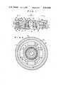
- FIG. 1is a sectional view showing a flywheel apparatus according to an embodiment of the present invention
- FIG. 2is a sectional view of the apparatus shown in FIG. 1 along the line II--II therein;
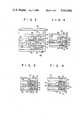
- FIG. 3is an enlarged partial view of the flywheel apparatus shown in FIG. 1;
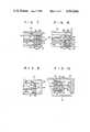
- FIGS. 4 to 10are partial sectional views of flywheel apparatuses according to other embodiments of the present invention.
- FIGS. 1 to 3show a flywheel apparatus according to an embodiment of the present invention.
- the apparatushas a base 12.
- the base 12consists of a hollow inner cylinder 14, a flange 16 formed integrally with the lower portion (FIG. 1) of the cylinder 14, and an outer cylinder 18 of a magnetic material which concentrically surrounds the inner cylinder 14 and has one end (lower end in FIG. 1) fixed to the upper outer periphery of the flange 16.
- a rotor 20 of a nonmagnetic materialis arranged radially outwardly of the base 12 so as to be rotatable around the central axis of the base 12 through a magnetic bearing to be described later. As shown in FIG.
- the rotor 20has a flat hollow cylindrical shape having an open lower end which covers the base 12 substantially coaxially with the central axis of the base 12.
- a hole 22 having a larger diameter than that of the inner cylinder 14 of the base 12is formed at the center of the upper end of the rotor 20 opposite to its open end so as to be coaxial with the axis or central axis of the inner cylinder 14.
- a support cylinder 24is fixed to the inner side wall of the rotor 20 so as to be coaxial therewith.
- the support cylinder 24has an inner diameter equal to the diameter of the hole 22 of the rotor 20 and extends toward the flange 16 of the base 12 and between the inner and outer cylinders 14 and 18 of the base 12.
- a brushless motor 26is arranged between the inner side wall of the rotor 20 and the flange 16 of the base 12.
- the brushless motor 26comprises a rotor 28 having an annular groove, the rotor 28 being fixed to the outer circumferential surface of the support cylinder 24, and a stator 30 received in the groove of the rotor 28, the stator 30 being fixed to the flange 16 of the base 12.
- the power supply terminal of the stator 30is electrically connected to the output terminal of a power supply device (not shown).
- a projecting ring 32is formed on the inner circumferential wall of the support cylinder 24 at a position halfway along the axial direction.
- the ring 32reduces the inner diameter of the support cylinder 24.
- Displacement sensors 34, 36, 38 and 40are formed at equal intervals on the outer circumferential surface of the inner cylinder 14 which is opposite of the ring 32 of the support cylinder 24.
- the sensor 40is not shown in FIG. 1.
- the sensors 34, 36, 38 and 40comprise, for example, distance measuring sensors of an eddy current type and produce distance outputs respectively corresponding to the distance between the ring 32 of the support cylinder 24 and the outer circumferential surface of the inner cylinder 14 of the base 12. If the sensors 34, 36, 38 and 40 are of the eddy current type, the ring 32 of the support cylinder 24 consists of a magnetic material.
- a pair of ball bearings 42are arranged between the outer circumferential surface of the inner cylinder 14 of the base 12 and the inner circumferential surface of the support cylinder 24 so as to be located above and below the sensors 34, 36, 38 and 40.
- the inner rings of the ball bearings 42are fixed to the outer circumferential surface of the inner cylinder 14 of the base 12, so that the ball bearings 42 can mechanically support the rotor 20 in an emergency or the like.
- the magnetic bearinghas a first annular plate 46 of a magnetic material housed in the rotor 20 to be coaxial with the central axis of the base 12.
- the first annular plate 46is magnetically and mechanically coupled to the outer cylinder 18 of the base 12 through four arms 48, 50, 52 and 54 of a magnetic material.
- the arms 48, 50, 52 and 54are arranged along the circumferential direction of the outer cylinder 18.
- a second annular plate 56 of magnetic material and of the same thickness as that of the first annular plate 46is fixed to the inner circumferential wall of the rotor 20 coaxially therewith.
- the first and second annular plates 46 and 56are opposite to each other along the radial direction.
- a first annular gap 58is defined between the first and second annular plates 46 and 56. It is to be noted that the first and second annular plates 46 and 56, the ring 32 of the support cylinder 24, and the sensors 34, 36, 38 and 40 are arranged on a single plane.
- a magnetic circuit sectionis arranged between the first and second annular plates 46 and 56 and forms two magnetic circuits along the central axis of the base 12 which have the first annular gap 58 as a common magnetic path.
- the magnetic circuit sectionhas a pair of first annular permanent magnets 62 and 64 fixed on the annular surfaces of the first annular plate 46.
- the first annular permanent magnets 62 and 64are magnetized to have poles N and S in FIG. 1.
- the first annular permanent magnets 62 and 64are magnetized in opposite directions.
- a pair of first yokes 66 and 68 of an annular plate shapeare fixed on the first annular permanent magnets 62 and 64, respectively. It is to be noted here that the inner and outer circumferential surfaces of the first annular permanent magnets 62 and 64 and the first yokes 66 and 68 are level with the inner and outer circumferential surfaces of the first annular plate 46.
- a pair of second annular permanent magnets 70 and 72are fixed on the annular surfaces of the second annular plate 56 of the rotor 20.
- the second annular permanent magnets 70 and 72have the same axial dimension as that of the first annular permanent magnets 62 and 64.
- the second annular permanent magnets 70 and 72are magnetized to have poles N and S shown in FIG. 1.
- the second annular permanent magnets 70 and 72are also magnetized along opposite directions.
- the magnetization direction of the second annular permanent magnets 70 and 72is opposite to that of the first annular permanent magnets 62 and 64 radially opposing them.
- a pair of second yokes 74 and 76 of annular plate shapeis fixed on the second annular permanent magnets 70 and 72, respectively.
- the second yokes 74 and 76are opposite to the first yokes 66 and 68 along the radial direction.
- the paired yokes 66 and 74define a second annular gap 78 therebetween, and the paired yokes 68 and 76 define a third annular gap 80 therebetween.
- the inner circumferential surfaces of the second annular permanent magnets 70 and 72 and of the second yokes 74 and 76are level with the inner circumferential surface of the second annular plate 56.
- the magnetic circuit sectionhas magnetic circuits M1 and M2 of magnetic paths X and Y, respectively, shown in FIG. 3.
- the magnetic circuit M1is defined by the first annular permanent magnet 62, the first annular plate 46, the first annular gap 58, the second annular plate 56, the second annular permanent magnet 70, the second yoke 74, the second annular gap 78, and the first yoke 66.
- the magnetic circuit M2is defined by the first annular permanent magnet 64, the first annular plate 46, the first annular gap 58, the second annular plate 56, the second annular permanent magnet 72, the second yoke 76, the third annular gap 80, and the first yoke 68.
- the density of the magnetic fluxes passing along the common magnetic path of the magnetic circuits M1 and M2, that is, the first annular gap 58,can be controlled at a plurality of positions along the circumferential direction of the first annular gap 56 by a magnetic flux density varying device.
- the magnetic flux density varying devicehas solenoids 82, 84, 86 and 88 wound around the magnetic arms 48, 50, 52 and 54, respectively.
- Power supply terminals (not shown) of the solenoids 82, 84, 86 and 88are electrically connected to a power supply control circuit (not shown) of a known zero power control scheme.
- the power supply control circuitcontrols the power supplied to the solenoids 82, 84, 86 and 88 in cooperation with the displacement sensors 34, 36, 38 and 40.
- the gap length of the first annular gap 58 between the first and second annular plates 46 and 56is decreased at a certain position along the circumferential direction, the gap length of the first annular gap 58 at a position 180° shifted from this position is increased.
- This irregularity in the gap distance of the first annular gap 58appears as a change in the outputs in the sensors 34, 36, 38 and 40.
- the magnetic flux density of the first magnetic gap 58 at such a narrowed positionis decreased by controlling the solenoid near this narrowed position.
- the gap length of the first annular gap 58increases at a certain position, the magnetic flux density of the first annular gap 58 at such an extended position is increased by the solenoid near this position. Thereafter, when the gap length of the first annular gap 58 becomes uniform including the narrowed and extended positions, the power supplied to the solenoid 82, 84, 86 and 88 is stopped. According to this power supply control circuit, the gap length of the first annular gap 58 is kept uniform along the circumferential direction, so that the rotor 20 can be easily centered with the base 12 in a stable manner. In other words, the rotor 20 is radially supported with respect to the base 12 in a noncontact manner by a plurality of active magnetic circuits defined by the arms 48, 50, 52 and 54, and the first and second annular plates 46 and 56.
- the rotor 20is supported with respect to the base 12 both axially and radially by the passive magnetic circuits M1 and M2 and the active magnetic circuits.
- the rotor 20is driven by the brushless motor 26 in this state, the rotor 20 is kept in a completely noncontact state and is rotated around the central axis of the base 12, so that the flywheel apparatus can function well.
- the value of Acan be decreased and/or the value of B can be increased in order to improve the stiffness K ⁇ of the rotor 20.
- the diameter B of the magnetic bearing 44can be increased, and K ⁇ can thus be increased.
- the mass of the rotary side (the second annular permanent magnets 70 and 72, the second yokes 74 and 76 and the second annular plate 56) of the magnetic bearing 44can be effectively used for increasing the angular momentum of the rotor 20 as compared to a conventional apparatus of the same type. If the angular momentum of the rotor 20 is the same as that in a conventional apparatus, the diameter of the rotor 20 and hence the flywheel apparatus can be rendered small.
- the value of Acan be decreased to increase K ⁇ .
- K ⁇can be increased while at the same time the axial size of the flywheel apparatus can be decreased. Therefore, the flywheel apparatus can be rendered flat.
- FIGS. 4 to 10show parts of flywheel apparatuses according to other embodiments of the present invention.
- the same reference numerals as in FIGS. 1 to 3denote the same parts in FIGS. 4 to 10, and a detailed description thereof will be omitted. Only those features of these other embodiments which are different from the first embodiment described above will be described below.
- the radially opposing peripheries of the paired yokes 66 and 74 and of paired yokes 68 and 76are thinner than the other peripheries thereof.
- the magnetic fluxes passing through the second and third annular gaps 78 and 80can be saturated at a higher density than those magnetic fluxes passing through the first annular gap 58.
- the ratio Ku/Krcan be rendered smaller and the value of K ⁇ can be increased further.
- the radially opposing end surfaces of the first and second annular plates 46 and 56have annular grooves 90 and 92, respectively. Then, the value of Ku in the above relation can be decreased, and the value of K ⁇ can also be increased.
- the outer circumferential surfaces of the first yokes 66 and 68 and the first annular plate 46extend radially outward from the outer circumferential surfaces of the first annular permanent magnets 62 and 64. Then, the magnetix fluxes passing through the first to third annular gaps 58, 78 and 80 can be concentrated on the outer circumferential surfaces of the first yokes 66 and 68.
- thin rings 94having conductivity and elasticity as electromagnetic dampers are arranged between the outer peripheries of the first yoke 66 and the first annular plate 46 and between the outer peripheries of the first annular plate 46 and the first yoke 68, respectively, so as to cover the outer circumferential surfaces of the first annular permanent magnets 62 and 64. Then, the axial vibration transmitted from the base 12 can be absorbed by the rings 94.
- the rotary side elements 56, 70, 72, 74 and 76 of the magnetic bearing 44can alternatively be mounted on the rotor 20 through buffer members, so as to absorb the axial vibration of the base 12 which may be transmitted to the rotor 20.
- third and fourth annular permanent magnets 96 and 98, and third and fourth annular yokes 100 and 102 which together constitute a third magnetic circuit M3are arranged below the first and second yokes 68 and 76.
- the same effect as that in the above embodimentscan be obtained when three magnetic circuits M1, M2 and M3 are arranged in this manner.
- the second annular permanent magnets 70 and 72 and the second yokes 74 and 76are omitted. Instead, a third annular yoke 104 is formed integrally with the second annular plate 56.
- the third annular yoke 104extends vertically from the upper and lower surfaces of the outer periphery of the second annular plate 56. The upper and lower ends of the third annular yoke 104 radially oppose the first yokes 66 and 68. Then, two magnetic circuits similar to the magnetic circuits M1 and M2 can be formed.
- the rotary side elements of the magnetic bearing 44are arranged radially inwardly of the stationary side elements thereof.
- the first annular plate 46can be circumferentially divided into sections to define gaps therebetween, or a plurality of notches can be formed along the circumferential direction of the first annular plate 46.
- the first annular plate 46can consist of rings which are stacked in the radial direction.
Landscapes
- Engineering & Computer Science (AREA)
- General Engineering & Computer Science (AREA)
- Remote Sensing (AREA)
- Aviation & Aerospace Engineering (AREA)
- Mechanical Engineering (AREA)
- Radar, Positioning & Navigation (AREA)
- Chemical & Material Sciences (AREA)
- Combustion & Propulsion (AREA)
- Physics & Mathematics (AREA)
- Power Engineering (AREA)
- Electromagnetism (AREA)
- Life Sciences & Earth Sciences (AREA)
- Environmental & Geological Engineering (AREA)
- General Life Sciences & Earth Sciences (AREA)
- Geochemistry & Mineralogy (AREA)
- Geology (AREA)
- Acoustics & Sound (AREA)
- Magnetic Bearings And Hydrostatic Bearings (AREA)
Abstract
Description
Kθ=(1/4)·Kr(B.sup.2 -(Ku·A.sup.2)/(2·Kr))
Claims (12)
Applications Claiming Priority (2)
| Application Number | Priority Date | Filing Date | Title |
|---|---|---|---|
| JP58-119313 | 1983-06-30 | ||
| JP58119313AJPS6011746A (en) | 1983-06-30 | 1983-06-30 | Fly wheel device |
Publications (1)
| Publication Number | Publication Date |
|---|---|
| US4563046Atrue US4563046A (en) | 1986-01-07 |
Family
ID=14758345
Family Applications (1)
| Application Number | Title | Priority Date | Filing Date |
|---|---|---|---|
| US06/625,617Expired - LifetimeUS4563046A (en) | 1983-06-30 | 1984-06-28 | Flywheel apparatus |
Country Status (4)
| Country | Link |
|---|---|
| US (1) | US4563046A (en) |
| EP (1) | EP0130541B1 (en) |
| JP (1) | JPS6011746A (en) |
| DE (1) | DE3470202D1 (en) |
Cited By (28)
| Publication number | Priority date | Publication date | Assignee | Title |
|---|---|---|---|---|
| US4644205A (en)* | 1984-09-29 | 1987-02-17 | Kabushiki Kaisha Toshiba | Positioning device of magnetic suspension type |
| US4901562A (en)* | 1989-03-31 | 1990-02-20 | Dana Corporation | Vehicle wheel speed sensor for a drive axle |
| US5043615A (en)* | 1989-08-14 | 1991-08-27 | Shibasoku Co., Ltd. | Noncontact bearing utilizing magnetism |
| US5106273A (en)* | 1990-03-07 | 1992-04-21 | Alcatel Cit | Vacuum pump for producing a clean molecular vacuum |
| US5111102A (en)* | 1989-05-25 | 1992-05-05 | Meeks Crawford R | Magnetic bearing structure |
| WO1992010871A1 (en)* | 1990-12-04 | 1992-06-25 | University Of Houston | High temperature superconducting magnetic bearings |
| US5152679A (en)* | 1990-08-10 | 1992-10-06 | Ebara Corporation | Turbo molecular pump |
| US5159219A (en)* | 1991-05-16 | 1992-10-27 | University Of Houston-University Park | Opposed-magnet bearing with interposed superconductor |
| US5216308A (en)* | 1989-05-25 | 1993-06-01 | Avcon-Advanced Controls Technology, Inc. | Magnetic bearing structure providing radial, axial and moment load bearing support for a rotatable shaft |
| US5250865A (en)* | 1992-04-30 | 1993-10-05 | Avcon - Advanced Controls Technology, Inc. | Electromagnetic thrust bearing for coupling a rotatable member to a stationary member |
| US5315197A (en)* | 1992-04-30 | 1994-05-24 | Avcon - Advance Controls Technology, Inc. | Electromagnetic thrust bearing using passive and active magnets, for coupling a rotatable member to a stationary member |
| US5514924A (en)* | 1992-04-30 | 1996-05-07 | AVCON--Advanced Control Technology, Inc. | Magnetic bearing providing radial and axial load support for a shaft |
| WO1996029775A1 (en)* | 1995-03-21 | 1996-09-26 | Teldix Gmbh | Magnetically mounted, position-stabilised flywheel |
| US20030052558A1 (en)* | 2001-09-17 | 2003-03-20 | Brackett Norman C. | Repulsive lift systems, flywheel energy storage systems utilizing such systems and methods related thereto |
| US6710489B1 (en)* | 2001-08-30 | 2004-03-23 | Indigo Energy, Inc. | Axially free flywheel system |
| US6794776B1 (en)* | 2001-10-15 | 2004-09-21 | Christopher W Gabrys | Inductor alternator flywheel system |
| US20080120876A1 (en)* | 2006-11-28 | 2008-05-29 | W.A. Krapf, Inc. | Magnetic bearing assembly for rotatable support apparatus |
| EP2060811A1 (en)* | 2007-11-16 | 2009-05-20 | Thales | Centring magnetic bearing with two levels |
| US20100026431A1 (en)* | 2008-07-29 | 2010-02-04 | Thales | Magnetically suspended gyroscopic actuator device |
| US20100283340A1 (en)* | 2009-05-08 | 2010-11-11 | Fradella Richard B | Low-Cost Minimal-Loss Flywheel Battery |
| US8803363B2 (en) | 2012-04-16 | 2014-08-12 | Temporal Power Ltd. | Method and system for regulating power of an electricity grid system |
| US9083207B1 (en) | 2014-01-10 | 2015-07-14 | Temporal Power Ltd. | High-voltage flywheel energy storage system |
| US9325217B2 (en) | 2010-06-08 | 2016-04-26 | Temporal Power Ltd. | Flywheel energy system |
| US20170081050A1 (en)* | 2015-09-18 | 2017-03-23 | Thales | Gyroscopic actuator with double gimbal guidance, suspension element and end-stop element |
| PL422674A1 (en)* | 2017-08-28 | 2019-03-11 | Bereska Damian Stefan | Storage and method for storing energy in the system of two coaxial elements rotating in opposed directions |
| US10508710B2 (en) | 2012-11-05 | 2019-12-17 | Bc New Energy (Tianjin) Co., Ltd. | Cooled flywheel apparatus having a stationary cooling member to cool a flywheel annular drive shaft |
| US10778061B2 (en) | 2018-11-07 | 2020-09-15 | Industrial Technology Research Institute | Flywheel energy storage system |
| US10931164B1 (en) | 2013-03-14 | 2021-02-23 | Paul D. Westfall | Mechanical energy and storage device |
Families Citing this family (14)
| Publication number | Priority date | Publication date | Assignee | Title |
|---|---|---|---|---|
| DE2712688C3 (en)* | 1977-03-23 | 1979-10-04 | Dynamit Nobel Ag, 5210 Troisdorf | Solvent-free molding compound based on polyvinyl chloride |
| DE3249423C2 (en)* | 1982-08-03 | 1986-02-27 | Wilhelm G. 8510 Fürth Scheller | Storage with magnetic ring structures |
| JPS61175314A (en)* | 1985-01-31 | 1986-08-07 | Natl Aerospace Lab | magnetic bearing |
| FR2642538B1 (en)* | 1989-01-31 | 1991-05-24 | Europ Propulsion | MECHANICAL STABILIZATION SYSTEM WITH COUNTER-ROTATION WITH FITTED ROTORS |
| DE19509799A1 (en)* | 1995-03-21 | 1996-09-26 | Teldix Gmbh | Magnetically mounted, vibration-damped flywheel |
| US5747907A (en)* | 1995-12-29 | 1998-05-05 | United Technologies Automotive, Inc. | Backup bearings for positive re-centering of magnetic bearings |
| DE59712591D1 (en) | 1997-08-25 | 2006-05-04 | Levitronix Llc | Magnetic bearing rotation arrangement |
| EP0899857B1 (en)* | 1997-08-25 | 2007-11-28 | LUST ANTRIEBSTECHNIK GmbH | Rotary device with magnetic bearing |
| JP2007132404A (en)* | 2005-11-09 | 2007-05-31 | Saxa Inc | Bearing structure of rotating body |
| CN102437675B (en)* | 2011-10-13 | 2016-01-06 | 山东科技大学 | Energy storage device of magnetic suspension flywheel |
| JP2016039733A (en)* | 2014-08-08 | 2016-03-22 | 中田 修 | Flywheel device, and power generation and drive motor device |
| DE102015114819B3 (en)* | 2015-09-04 | 2016-12-22 | Rockwell Collins Deutschland Gmbh | Spin wheel device for position stabilization of a spacecraft |
| US10947986B2 (en)* | 2018-07-11 | 2021-03-16 | Ch Biomedical (Usa) Inc. | Compact centrifugal pump with magnetically suspended impeller |
| JP2020128745A (en) | 2019-02-01 | 2020-08-27 | ホワイト ナイト フルイド ハンドリング インコーポレーテッドWhite Knight Fluid Handling Inc. | Pump having magnet for journaling and magnetically axially positioning rotor thereof, and related method |
Citations (15)
| Publication number | Priority date | Publication date | Assignee | Title |
|---|---|---|---|---|
| US3845995A (en)* | 1972-03-08 | 1974-11-05 | Teldix Gmbh | Magnetically mounted rotor |
| FR2257077A1 (en)* | 1974-01-03 | 1975-08-01 | Aerospatiale | Artificial moon inertia flywheel - has magnetic radial and axial centring mechanisms and damper also motor generator |
| US3955858A (en)* | 1974-01-03 | 1976-05-11 | Societe Nationale Industrielle Aerospatiale | Satellite momentum wheel |
| FR2329890A1 (en)* | 1975-10-28 | 1977-05-27 | Cambridge Thermionic Corp | MAGNETIC SUSPENSION DEVICE |
| US4077678A (en)* | 1976-07-30 | 1978-03-07 | The United States Of America As Represented By The Administrator Of The National Aeronautics And Space Administration | Energy storage apparatus |
| FR2384174A1 (en)* | 1977-03-15 | 1978-10-13 | Aerospatiale | INERTIA WHEEL |
| DE2842165A1 (en)* | 1978-09-28 | 1980-04-17 | Teldix Gmbh | Magnetic bearing with rotor ring - has rings on pole plates with radial protrusions accommodating stabiliser coils |
| GB2033977A (en)* | 1978-09-28 | 1980-05-29 | Teldix Gmbh | Flywheel |
| US4285552A (en)* | 1980-02-11 | 1981-08-25 | Sperry Corporation | Torquer apparatus for magnetically suspended members |
| JPS56147942A (en)* | 1980-04-16 | 1981-11-17 | Toshiba Corp | Flywheel |
| EP0049300A1 (en)* | 1980-10-03 | 1982-04-14 | Mitsubishi Precision Co., Ltd. | A magnetically suspended type momentum ring assembly |
| JPS5765443A (en)* | 1980-10-09 | 1982-04-21 | Toshiba Corp | Flywheel |
| FR2524090A1 (en)* | 1982-03-26 | 1983-09-30 | Aerospatiale | MAGNETIC SUSPENSION DEVICE FOR INERTIA WHEEL |
| US4443043A (en)* | 1981-09-09 | 1984-04-17 | Tokyo Shibaura Denki Kabushiki Kaisha | Electric motor unit |
| US4483570A (en)* | 1982-02-26 | 1984-11-20 | Mitsubishi Denki Kabushiki Kaisha | Magnetic bearing arrangement for an artificial satellite |
- 1983
- 1983-06-30JPJP58119313Apatent/JPS6011746A/enactiveGranted
- 1984
- 1984-06-26EPEP84107353Apatent/EP0130541B1/ennot_activeExpired
- 1984-06-26DEDE8484107353Tpatent/DE3470202D1/ennot_activeExpired
- 1984-06-28USUS06/625,617patent/US4563046A/ennot_activeExpired - Lifetime
Patent Citations (16)
| Publication number | Priority date | Publication date | Assignee | Title |
|---|---|---|---|---|
| US3845995A (en)* | 1972-03-08 | 1974-11-05 | Teldix Gmbh | Magnetically mounted rotor |
| FR2257077A1 (en)* | 1974-01-03 | 1975-08-01 | Aerospatiale | Artificial moon inertia flywheel - has magnetic radial and axial centring mechanisms and damper also motor generator |
| US3955858A (en)* | 1974-01-03 | 1976-05-11 | Societe Nationale Industrielle Aerospatiale | Satellite momentum wheel |
| FR2329890A1 (en)* | 1975-10-28 | 1977-05-27 | Cambridge Thermionic Corp | MAGNETIC SUSPENSION DEVICE |
| US4077678A (en)* | 1976-07-30 | 1978-03-07 | The United States Of America As Represented By The Administrator Of The National Aeronautics And Space Administration | Energy storage apparatus |
| US4211452A (en)* | 1977-03-15 | 1980-07-08 | Societe Nationale Industrielle Aerospatiale | Inertia wheel |
| FR2384174A1 (en)* | 1977-03-15 | 1978-10-13 | Aerospatiale | INERTIA WHEEL |
| DE2842165A1 (en)* | 1978-09-28 | 1980-04-17 | Teldix Gmbh | Magnetic bearing with rotor ring - has rings on pole plates with radial protrusions accommodating stabiliser coils |
| GB2033977A (en)* | 1978-09-28 | 1980-05-29 | Teldix Gmbh | Flywheel |
| US4285552A (en)* | 1980-02-11 | 1981-08-25 | Sperry Corporation | Torquer apparatus for magnetically suspended members |
| JPS56147942A (en)* | 1980-04-16 | 1981-11-17 | Toshiba Corp | Flywheel |
| EP0049300A1 (en)* | 1980-10-03 | 1982-04-14 | Mitsubishi Precision Co., Ltd. | A magnetically suspended type momentum ring assembly |
| JPS5765443A (en)* | 1980-10-09 | 1982-04-21 | Toshiba Corp | Flywheel |
| US4443043A (en)* | 1981-09-09 | 1984-04-17 | Tokyo Shibaura Denki Kabushiki Kaisha | Electric motor unit |
| US4483570A (en)* | 1982-02-26 | 1984-11-20 | Mitsubishi Denki Kabushiki Kaisha | Magnetic bearing arrangement for an artificial satellite |
| FR2524090A1 (en)* | 1982-03-26 | 1983-09-30 | Aerospatiale | MAGNETIC SUSPENSION DEVICE FOR INERTIA WHEEL |
Non-Patent Citations (4)
| Title |
|---|
| Patents Abstracts of Japan, vol. 6, No. 142 (M 146) 1020 , 31st Jul. 1982; & JP A 57 65 443 (Tokyo Shibaura Denki K.K.) 21 04 1982.* |
| Patents Abstracts of Japan, vol. 6, No. 142 (M-146) [1020], 31st Jul. 1982; & JP-A-57 65 443 (Tokyo Shibaura Denki K.K.) 21-04-1982. |
| Patents Abstracts of Japan, vol. 6, No. 33 (M 114) 911 , 27th Feb. 1982; & JP A 56 147 942 (Tokyo Shibaura Denki K.K.) 17 11 1981.* |
| Patents Abstracts of Japan, vol. 6, No. 33 (M-114) [911], 27th Feb. 1982; & JP-A-56 147 942 (Tokyo Shibaura Denki K.K.) 17-11-1981. |
Cited By (35)
| Publication number | Priority date | Publication date | Assignee | Title |
|---|---|---|---|---|
| US4644205A (en)* | 1984-09-29 | 1987-02-17 | Kabushiki Kaisha Toshiba | Positioning device of magnetic suspension type |
| US4901562A (en)* | 1989-03-31 | 1990-02-20 | Dana Corporation | Vehicle wheel speed sensor for a drive axle |
| US5216308A (en)* | 1989-05-25 | 1993-06-01 | Avcon-Advanced Controls Technology, Inc. | Magnetic bearing structure providing radial, axial and moment load bearing support for a rotatable shaft |
| US5111102A (en)* | 1989-05-25 | 1992-05-05 | Meeks Crawford R | Magnetic bearing structure |
| US5043615A (en)* | 1989-08-14 | 1991-08-27 | Shibasoku Co., Ltd. | Noncontact bearing utilizing magnetism |
| US5106273A (en)* | 1990-03-07 | 1992-04-21 | Alcatel Cit | Vacuum pump for producing a clean molecular vacuum |
| US5152679A (en)* | 1990-08-10 | 1992-10-06 | Ebara Corporation | Turbo molecular pump |
| US5177387A (en)* | 1990-12-04 | 1993-01-05 | University Of Houston-University Park | High temperature superconducting magnetic bearings |
| WO1992010871A1 (en)* | 1990-12-04 | 1992-06-25 | University Of Houston | High temperature superconducting magnetic bearings |
| US5159219A (en)* | 1991-05-16 | 1992-10-27 | University Of Houston-University Park | Opposed-magnet bearing with interposed superconductor |
| US5250865A (en)* | 1992-04-30 | 1993-10-05 | Avcon - Advanced Controls Technology, Inc. | Electromagnetic thrust bearing for coupling a rotatable member to a stationary member |
| US5315197A (en)* | 1992-04-30 | 1994-05-24 | Avcon - Advance Controls Technology, Inc. | Electromagnetic thrust bearing using passive and active magnets, for coupling a rotatable member to a stationary member |
| US5514924A (en)* | 1992-04-30 | 1996-05-07 | AVCON--Advanced Control Technology, Inc. | Magnetic bearing providing radial and axial load support for a shaft |
| WO1996029775A1 (en)* | 1995-03-21 | 1996-09-26 | Teldix Gmbh | Magnetically mounted, position-stabilised flywheel |
| US5925952A (en)* | 1995-03-21 | 1999-07-20 | Teldix Gmbh | Magnetically mounted, position-stabilized flywheel |
| US6710489B1 (en)* | 2001-08-30 | 2004-03-23 | Indigo Energy, Inc. | Axially free flywheel system |
| US7679245B2 (en) | 2001-09-17 | 2010-03-16 | Beacon Power Corporation | Repulsive lift systems, flywheel energy storage systems utilizing such systems and methods related thereto |
| US20030052558A1 (en)* | 2001-09-17 | 2003-03-20 | Brackett Norman C. | Repulsive lift systems, flywheel energy storage systems utilizing such systems and methods related thereto |
| US6794776B1 (en)* | 2001-10-15 | 2004-09-21 | Christopher W Gabrys | Inductor alternator flywheel system |
| US7851957B2 (en) | 2006-11-28 | 2010-12-14 | W.A. Krapf, Inc. | Magnetic bearing assembly for rotatable support apparatus |
| US20080120876A1 (en)* | 2006-11-28 | 2008-05-29 | W.A. Krapf, Inc. | Magnetic bearing assembly for rotatable support apparatus |
| EP2060811A1 (en)* | 2007-11-16 | 2009-05-20 | Thales | Centring magnetic bearing with two levels |
| US20100026431A1 (en)* | 2008-07-29 | 2010-02-04 | Thales | Magnetically suspended gyroscopic actuator device |
| US8242649B2 (en) | 2009-05-08 | 2012-08-14 | Fradella Richard B | Low-cost minimal-loss flywheel battery |
| US20100283340A1 (en)* | 2009-05-08 | 2010-11-11 | Fradella Richard B | Low-Cost Minimal-Loss Flywheel Battery |
| US9325217B2 (en) | 2010-06-08 | 2016-04-26 | Temporal Power Ltd. | Flywheel energy system |
| US8803363B2 (en) | 2012-04-16 | 2014-08-12 | Temporal Power Ltd. | Method and system for regulating power of an electricity grid system |
| US10508710B2 (en) | 2012-11-05 | 2019-12-17 | Bc New Energy (Tianjin) Co., Ltd. | Cooled flywheel apparatus having a stationary cooling member to cool a flywheel annular drive shaft |
| US10931164B1 (en) | 2013-03-14 | 2021-02-23 | Paul D. Westfall | Mechanical energy and storage device |
| US11677295B1 (en) | 2013-03-14 | 2023-06-13 | Paul D. Westfall | Mechanical energy and storage device |
| US9083207B1 (en) | 2014-01-10 | 2015-07-14 | Temporal Power Ltd. | High-voltage flywheel energy storage system |
| US9362801B2 (en) | 2014-01-10 | 2016-06-07 | Temporal Power Ltd. | High-voltage flywheel energy storage system |
| US20170081050A1 (en)* | 2015-09-18 | 2017-03-23 | Thales | Gyroscopic actuator with double gimbal guidance, suspension element and end-stop element |
| PL422674A1 (en)* | 2017-08-28 | 2019-03-11 | Bereska Damian Stefan | Storage and method for storing energy in the system of two coaxial elements rotating in opposed directions |
| US10778061B2 (en) | 2018-11-07 | 2020-09-15 | Industrial Technology Research Institute | Flywheel energy storage system |
Also Published As
| Publication number | Publication date |
|---|---|
| EP0130541A1 (en) | 1985-01-09 |
| JPH0137608B2 (en) | 1989-08-08 |
| EP0130541B1 (en) | 1988-03-30 |
| DE3470202D1 (en) | 1988-05-05 |
| JPS6011746A (en) | 1985-01-22 |
Similar Documents
| Publication | Publication Date | Title |
|---|---|---|
| US4563046A (en) | Flywheel apparatus | |
| US4652780A (en) | Magnetic bearing device | |
| US4918345A (en) | Magnetic bearing for active centering of a body movable relative to a static body with respect to at least one axis | |
| JP3786420B2 (en) | Magnetic bearing cell having a rotor and a stator | |
| EP0225616B1 (en) | Electric motor | |
| US6121704A (en) | Magnetic bearing | |
| JP2826156B2 (en) | Spindle motor | |
| US4340261A (en) | Magnetic bearing arrangement | |
| US3954310A (en) | Radial magnetic bearing | |
| EP0687827A1 (en) | Hybrid magnetic/foil gas bearings | |
| JPS5942165B2 (en) | Magnetic non-contact bearing device | |
| US5804899A (en) | Miniature magnetic bearing with at least one active axis | |
| KR100701550B1 (en) | Bearingless Step Motor | |
| KR20010062764A (en) | Magnetic bearing apparatus | |
| JPS6146683B2 (en) | ||
| JP2002257136A (en) | Magnetic bearing | |
| RU2037684C1 (en) | Electromagnetic support | |
| US4891997A (en) | Dynamically tuned gyro | |
| US6362549B1 (en) | Magnetic bearing device | |
| JPH09303395A (en) | Magnetic bearing device | |
| JPH0942289A (en) | Hybrid magnetic/wheel-gas-bearing | |
| JPH1162878A (en) | Turbo molecular pump | |
| JPH0226310A (en) | Magnetic thrust bearing | |
| US20050253473A1 (en) | Alternative magnetic bearing | |
| JPS6399742A (en) | Magnetic bearing integrating type motor |
Legal Events
| Date | Code | Title | Description |
|---|---|---|---|
| AS | Assignment | Owner name:KABUSHIKI KAISHA TOSHIBA 72 HORIKAWA-CHO, SAIWAI-K Free format text:ASSIGNMENT OF ASSIGNORS INTEREST.;ASSIGNOR:SHIMAMOTO, YOSHIHARU;REEL/FRAME:004461/0063 Effective date:19850116 Owner name:DIRECTOR-GENERAL OF NATIONAL AEROSPACE LABORATORY Free format text:ASSIGNMENT OF ASSIGNORS INTEREST.;ASSIGNOR:SHIMAMOTO, YOSHIHARU;REEL/FRAME:004461/0063 Effective date:19850116 | |
| STCF | Information on status: patent grant | Free format text:PATENTED CASE | |
| FEPP | Fee payment procedure | Free format text:PAYOR NUMBER ASSIGNED (ORIGINAL EVENT CODE: ASPN); ENTITY STATUS OF PATENT OWNER: LARGE ENTITY | |
| FPAY | Fee payment | Year of fee payment:4 | |
| FPAY | Fee payment | Year of fee payment:8 | |
| FPAY | Fee payment | Year of fee payment:12 | |
| AS | Assignment | Owner name:KABUSHIKI KAISHA TOSHIBA, JAPAN Free format text:CORPORATE ADDRESS CHANGE;ASSIGNOR:KABUSHIKI KAISHA TOSHIBA;REEL/FRAME:012287/0654 Effective date:20010701 | |
| AS | Assignment | Owner name:NEC TOSHIBA SPACE SYSTEMS, LTD., JAPAN Free format text:ASSIGNMENT OF ASSIGNORS INTEREST;ASSIGNOR:KABUSHIKI KAISHA TOSHIBA;REEL/FRAME:012958/0820 Effective date:20011001 |