US4561799A - Torque joint - Google Patents
Torque jointDownload PDFInfo
- Publication number
- US4561799A US4561799AUS06/649,284US64928484AUS4561799AUS 4561799 AUS4561799 AUS 4561799AUS 64928484 AUS64928484 AUS 64928484AUS 4561799 AUS4561799 AUS 4561799A
- Authority
- US
- United States
- Prior art keywords
- mandrel
- joint
- torque
- members
- circumferential
- Prior art date
- Legal status (The legal status is an assumption and is not a legal conclusion. Google has not performed a legal analysis and makes no representation as to the accuracy of the status listed.)
- Expired - Lifetime
Links
- 238000010276constructionMethods0.000claimsdescription11
- 238000005452bendingMethods0.000claims1
- 230000005540biological transmissionEffects0.000abstractdescription8
- 238000004519manufacturing processMethods0.000description6
- 230000015572biosynthetic processEffects0.000description5
- 239000000463materialSubstances0.000description5
- 238000000605extractionMethods0.000description3
- 238000000034methodMethods0.000description3
- 230000035939shockEffects0.000description3
- XEEYBQQBJWHFJM-UHFFFAOYSA-NIronChemical compound[Fe]XEEYBQQBJWHFJM-UHFFFAOYSA-N0.000description2
- 230000000717retained effectEffects0.000description2
- 229910000831SteelInorganic materials0.000description1
- XAGFODPZIPBFFR-UHFFFAOYSA-NaluminiumChemical compound[Al]XAGFODPZIPBFFR-UHFFFAOYSA-N0.000description1
- 229910052782aluminiumInorganic materials0.000description1
- 239000004020conductorSubstances0.000description1
- 239000012530fluidSubstances0.000description1
- 238000007373indentationMethods0.000description1
- 229910052742ironInorganic materials0.000description1
- 239000007788liquidSubstances0.000description1
- 239000000314lubricantSubstances0.000description1
- 230000013011matingEffects0.000description1
- 238000012986modificationMethods0.000description1
- 230000004048modificationEffects0.000description1
- 239000007787solidSubstances0.000description1
- 239000010959steelSubstances0.000description1
Images


Classifications
- B—PERFORMING OPERATIONS; TRANSPORTING
- B21—MECHANICAL METAL-WORKING WITHOUT ESSENTIALLY REMOVING MATERIAL; PUNCHING METAL
- B21D—WORKING OR PROCESSING OF SHEET METAL OR METAL TUBES, RODS OR PROFILES WITHOUT ESSENTIALLY REMOVING MATERIAL; PUNCHING METAL
- B21D26/00—Shaping without cutting otherwise than using rigid devices or tools or yieldable or resilient pads, i.e. applying fluid pressure or magnetic forces
- B21D26/14—Shaping without cutting otherwise than using rigid devices or tools or yieldable or resilient pads, i.e. applying fluid pressure or magnetic forces applying magnetic forces
- B—PERFORMING OPERATIONS; TRANSPORTING
- B21—MECHANICAL METAL-WORKING WITHOUT ESSENTIALLY REMOVING MATERIAL; PUNCHING METAL
- B21D—WORKING OR PROCESSING OF SHEET METAL OR METAL TUBES, RODS OR PROFILES WITHOUT ESSENTIALLY REMOVING MATERIAL; PUNCHING METAL
- B21D39/00—Application of procedures in order to connect objects or parts, e.g. coating with sheet metal otherwise than by plating; Tube expanders
- B21D39/04—Application of procedures in order to connect objects or parts, e.g. coating with sheet metal otherwise than by plating; Tube expanders of tubes with tubes; of tubes with rods
- B—PERFORMING OPERATIONS; TRANSPORTING
- B23—MACHINE TOOLS; METAL-WORKING NOT OTHERWISE PROVIDED FOR
- B23P—METAL-WORKING NOT OTHERWISE PROVIDED FOR; COMBINED OPERATIONS; UNIVERSAL MACHINE TOOLS
- B23P11/00—Connecting or disconnecting metal parts or objects by metal-working techniques not otherwise provided for
- F—MECHANICAL ENGINEERING; LIGHTING; HEATING; WEAPONS; BLASTING
- F16—ENGINEERING ELEMENTS AND UNITS; GENERAL MEASURES FOR PRODUCING AND MAINTAINING EFFECTIVE FUNCTIONING OF MACHINES OR INSTALLATIONS; THERMAL INSULATION IN GENERAL
- F16D—COUPLINGS FOR TRANSMITTING ROTATION; CLUTCHES; BRAKES
- F16D1/00—Couplings for rigidly connecting two coaxial shafts or other movable machine elements
- F16D1/02—Couplings for rigidly connecting two coaxial shafts or other movable machine elements for connecting two abutting shafts or the like
- F16D1/027—Couplings for rigidly connecting two coaxial shafts or other movable machine elements for connecting two abutting shafts or the like non-disconnectable, e.g. involving gluing, welding or the like
- Y—GENERAL TAGGING OF NEW TECHNOLOGICAL DEVELOPMENTS; GENERAL TAGGING OF CROSS-SECTIONAL TECHNOLOGIES SPANNING OVER SEVERAL SECTIONS OF THE IPC; TECHNICAL SUBJECTS COVERED BY FORMER USPC CROSS-REFERENCE ART COLLECTIONS [XRACs] AND DIGESTS
- Y10—TECHNICAL SUBJECTS COVERED BY FORMER USPC
- Y10T—TECHNICAL SUBJECTS COVERED BY FORMER US CLASSIFICATION
- Y10T403/00—Joints and connections
- Y10T403/49—Member deformed in situ
- Y10T403/4991—Both members deformed
- Y—GENERAL TAGGING OF NEW TECHNOLOGICAL DEVELOPMENTS; GENERAL TAGGING OF CROSS-SECTIONAL TECHNOLOGIES SPANNING OVER SEVERAL SECTIONS OF THE IPC; TECHNICAL SUBJECTS COVERED BY FORMER USPC CROSS-REFERENCE ART COLLECTIONS [XRACs] AND DIGESTS
- Y10—TECHNICAL SUBJECTS COVERED BY FORMER USPC
- Y10T—TECHNICAL SUBJECTS COVERED BY FORMER US CLASSIFICATION
- Y10T403/00—Joints and connections
- Y10T403/70—Interfitted members
- Y10T403/7026—Longitudinally splined or fluted rod
Definitions
- This inventionrelates to mechanical systems for the transmission of torque and, more particularly, to a joint and a method of fabricating such joint between two tubular members which transmit a torque.
- Mechanical members for the transmission of torqueare found in a large variety of mechanical systems ranging from automobiles to aircraft.
- such structureis found in the drive shaft of an automobile as well as in a drag link used in an automobile steering mechanism.
- such structuremay be found in the mechanism for positioning airflow surfaces in an aircraft.
- the joining of two mechanical membersis accomplished by means of a joint which is so configured so as to be able to transmit the torque.
- the membersare of tubular construction so as to provide for a savings in weight.
- the joining together of the membersis accomplished with the aid of some form of indentation, as by the use of teeth or axial slots or grooves, so as to insure the transmission of torque without a circumferential slipping between the two members.
- one of the membersis provided with a solid core while the second member is of tubular construction.
- the tubular shaftis then swaged upon the core of the other member so as to provide grooves within the tubular member, the grooves of the tublar member being nested within the grooves of the core so as to provide for the transmission of torque.
- an inner rotating mandrel and outer rotating rollermay be utilized to impress a circumferential groove within two overlapping cylindrical structures as is disclosed in the U.S. Pat. No. 2,233,471.
- Another method of joining two tubular structures in a rigid joint configured for both axial tension and torque transmissionis the use of a magnetic pulse for developing a momentary intense force which deforms the material of the two members as is disclosed in the U.S. Pat. No. 2,976,907.
- a strong shock induced in a fluid transmitting medium surrounding the work pieces to be joinedmay be utilized as is disclosed in the U.S. Pat.
- a torque jointwhich, in accordance with the invention, provides for the joining together of two thin wall tubular members.
- the tubesare of different diameters to permit the sliding of one tube within the other so that their respective ends overlap at the site of the torque joint.
- the wall of each memberis sufficiently thin so as to permit a deformation in the walls of both members at the site of overlap of such members in the formation of the torque joint.
- two cylindrical mandrelsare inserted from opposite ends of the torque joint being fabricated and butted up against each other, each of the mandrels having longitudinal grooves which are to be utilized in the forming of grooves in the two tubular members.
- the ends of the mandrelsare chamfered so as to provide a circumferential groove at the site of the abutment of the ends of the two mandrels.
- a coil of wire carrying a strong current pulseencircles the overlap region of the members with the mandrels therein.
- the current pulseinduces a strong magnetic field which interacts with the tubular members to compress them against the mandrels and to deform the members so as to provide for the axial and circumferential grooves.
- the tubular membersare fabricated of current-conducting material of low resistivity to insure that a strong force is exerted on the tubular members in the magnetic field for the formation of the torque joint.
- one mandrel plus a ring which also serves the mandrel functionare utilized for the formation of the torque joint.
- the ringis inserted ahead of the mandrel, so as to lie within the tubular member having the closed end.
- the ring plus the chamfered end of the one mandrelprovide for a circumferential groove, while the longitudinal grooves are provided by the one mandrel.
- the circumferential and axial groovesare formed within both members at the site of their overlap.
- the one mandrelis then removed; however, the ring is retained within the torque joint, the ring having been captured by the circumferential groove and the closed end of the tubular member.
- FIG. 1is an elevation view of one or two mandrels for use in the formation of a torque joint between two open-ended tubular members in accordance with the invention
- FIG. 2is an elevation view of a mandrel for use with a retainer ring in forming the torque joint between a closed end and an open-ended tubular member in accordance with the second aspect of the invention
- FIG. 3is an end view of the mandrel shown in FIG. 2;
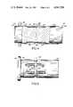
- FIG. 4shows a torque joint formed between two open-ended tubular members using the mandrel of FIG. 1, the tubular members and the mandrel being sectioned to show one mandrel within each half of the torque joint during the fabrication thereof;
- FIG. 5is an elevation view of the completed torque joint of FIG. 4 upon removal of the mandrels
- FIG. 6is a view, similar to that of FIG. 4, showing the use of the mandrel and the retainer ring of FIG. 2 in the formation of a torque joint with a closed end and an open end tubular member, the tubular members and the mandrel and the retainer ring being sectioned to show the mandrel and the retainer ring;
- FIG. 7is an elevation view of the completed torque joint of FIG. 6 upon removal of the mandrel.
- a mandrel 20is formed of a rigid material, such as iron or steel, and includes a cylindrical surface 22 having axially disposed grooves 24 therein.
- the grooves 24terminate in a circumferential chamfer 26 of a reduced diameter and having a curvature for forming one-half of a circumferential slot in a torque joint as will be described subsequently.
- a mandrel 28is constructed of the same material as the mandrel 20 of FIG. 1, and is provided with a cylindrical surface 30 having axially disposed grooves 32 therein.
- the grooves 32terminate in a skirt 34 of a reduced diameter.
- the skirt 34has a curvature at the end thereof for forming one edge of a circumferential slot for a torque joint as will be disclosed subsequently.
- a shelf 36having a cylindrical surface of still a further reduced diameter for mating with the inner surface of a retaining ring as will be disclosed with reference to FIG. 6.
- a torque joint 38comprises the overlapped region of an inner tubular member 40 and an outer tubular member 42.
- the inner tubular member 40is provided with an adapter for connection with further structure (not shown), in the form of a collar 44 extending radially outward from the end of the tubular member 40.
- Two mandrels 20, of the form disclosed in FIG. 1are inserted from opposite ends of the joint 38 and butted up against each other whereby the circumferential chamfers 26 of each of the mandrels 20 provide a circumferential groove 46.
- the material of the members 40 and 42is forced inwardly into the grooves 24 and the groove 46 to provide a pattern of grooves within the walls of the tubular members 40 and 42.
- the groove pattern 48encircles the torque joint 38 and includes a circumferential slot or groove 50 with axially disposed grooves 52 extending sidewise thereof.
- a torque joint 54comprises the overlapping region between an inner tubular member 56 and an outer tubular member 58.
- the inner tubular member 56terminates in an adapter having the form of a fitting 60 which closes off the end of the inner tubular member 56.
- a retainer ring 62is inserted in the open end of the outer member 58 and pushed into place by the mandrel 28.
- the shelf 36 of the mandrel 28engages the inner surface of the ring 62.
- the edge of the ring 62 facing the mandrel 28is chamfered to provide, in combination with the skirt 34, a circumferential slot or groove 64.
- the groove pattern 66has a circumferential groove 68 with axially disposed grooves 70 extending from the sides thereof.
- the torque joint 38 of FIGS. 4 and 5is fabricated by first inserting the end of the inner member 40 into the outer member 42 to provide an overlapping of the members 40 and 42. Thereupon, the two mandrels 20 are inserted into abutting position. The deformation force is then applied followed by the extraction of the mandrels 20.
- the mandrels 20are coated with a lubricant to facilitate their extraction.
- the analogous procedureis followed wherein the end of the inner tubular member 56 is inserted within the open end of the outer tubular member 58 to provide an overlapping relationship.
- the retainer ring 62 and the mandrel 28are then inserted via the open end of the outer member 58. Thereupon, the deformation force is applied followed by an extraction of the mandrel 28.
- the ring 62remains in its location, having been captured beteen the circumferential groove 68 of the joint 54 and the fitting 60.
Landscapes
- Engineering & Computer Science (AREA)
- Mechanical Engineering (AREA)
- General Engineering & Computer Science (AREA)
- Physics & Mathematics (AREA)
- Fluid Mechanics (AREA)
- Shafts, Cranks, Connecting Bars, And Related Bearings (AREA)
Abstract
Description
Claims (1)
Priority Applications (1)
| Application Number | Priority Date | Filing Date | Title |
|---|---|---|---|
| US06/649,284US4561799A (en) | 1982-02-08 | 1984-09-11 | Torque joint |
Applications Claiming Priority (2)
| Application Number | Priority Date | Filing Date | Title |
|---|---|---|---|
| US06/347,074US4513488A (en) | 1982-02-08 | 1982-02-08 | Method of fabricating a torque joint |
| US06/649,284US4561799A (en) | 1982-02-08 | 1984-09-11 | Torque joint |
Related Parent Applications (1)
| Application Number | Title | Priority Date | Filing Date |
|---|---|---|---|
| US06/347,074DivisionUS4513488A (en) | 1982-02-08 | 1982-02-08 | Method of fabricating a torque joint |
Publications (1)
| Publication Number | Publication Date |
|---|---|
| US4561799Atrue US4561799A (en) | 1985-12-31 |
Family
ID=26995118
Family Applications (1)
| Application Number | Title | Priority Date | Filing Date |
|---|---|---|---|
| US06/649,284Expired - LifetimeUS4561799A (en) | 1982-02-08 | 1984-09-11 | Torque joint |
Country Status (1)
| Country | Link |
|---|---|
| US (1) | US4561799A (en) |
Cited By (24)
| Publication number | Priority date | Publication date | Assignee | Title |
|---|---|---|---|---|
| US4826346A (en)* | 1985-04-11 | 1989-05-02 | Mitsubishi Jukogyo Kabushiki Kaisha | Camshaft preferably for an internal combustion engine |
| US5304012A (en)* | 1992-07-01 | 1994-04-19 | Curtiss Wright Flight Systems Inc. | Drive shaft fitting or coupling |
| US5643093A (en)* | 1995-10-19 | 1997-07-01 | Dana Corporation | Aluminum driveshaft having reduced diameter end portion |
| US5671522A (en)* | 1996-01-29 | 1997-09-30 | Northrop Grumman Corporation | Method and apparatus for sealing a pressure vessel |
| US5692853A (en)* | 1995-11-27 | 1997-12-02 | Curtiss Wright Flight Systems Inc. | Threaded joint construction and rod assembly incorporating same |
| WO1997048507A1 (en)* | 1996-06-18 | 1997-12-24 | Northrop Grumman Corporation | Method and forming die for fabricating spiral groove torque tube assemblies |
| US5983478A (en)* | 1996-09-18 | 1999-11-16 | The Boeing Company | Tube forming on an end fitting |
| US6001018A (en)* | 1995-03-21 | 1999-12-14 | Dana Corporation | Method of manufacturing a drive line assembly |
| US6375381B1 (en) | 2000-01-06 | 2002-04-23 | Curtiss Wright Flight Systems, Inc. | Machine element/assembly and magneform joint |
| US20040055133A1 (en)* | 2002-09-24 | 2004-03-25 | Saha Pradip K. | Low chamfer angled torque tube end fitting metal |
| US20040081509A1 (en)* | 2002-10-15 | 2004-04-29 | Hitachi Unisia Autimotive Ltd. | Structure and method of coupling shaft member and cylindrical member |
| WO2003089145A3 (en)* | 2002-04-19 | 2004-08-05 | Bell Helicopter Textron Inc | Composite drive shaft with captured end adapters |
| US20050051224A1 (en)* | 2002-09-24 | 2005-03-10 | The Boeing Company | Low chamfer angled torque tube end fitting with elongated overflow groove |
| US20060005393A1 (en)* | 2004-07-08 | 2006-01-12 | Nelson Wagner | Method of manufacturing a combined driveshaft tube and yoke assembly |
| CN101432531B (en)* | 2004-09-02 | 2010-12-08 | 布林克曼产品公司 | Keyway, and method of holding a key in a keyway |
| US20170037910A1 (en)* | 2015-08-04 | 2017-02-09 | The Boeing Company | Torque tube assemblies for use with aircraft high lift devices |
| EP2998632A4 (en)* | 2013-05-17 | 2017-05-10 | NSK Ltd. | Joint structure, and joining method therefor |
| US20170191520A1 (en)* | 2015-12-31 | 2017-07-06 | Moog Inc. | Composite torque tube end fitting attachment method |
| WO2018024701A1 (en)* | 2016-08-01 | 2018-02-08 | Thyssenkrupp Presta Ag | Method for producing a steering shaft part and steering shaft for a motor vehicle |
| EP3822164A1 (en)* | 2019-11-15 | 2021-05-19 | Hamilton Sundstrand Corporation | Axial load capable torque tube assembly & manufacturing methods thereof |
| US11053983B2 (en) | 2018-01-19 | 2021-07-06 | The Boeing Company | Torque tube assemblies for use with aircraft high lift devices |
| US11060566B2 (en) | 2018-01-19 | 2021-07-13 | The Boeing Company | Apparatus and methods for rigging a torque tube assembly in an aircraft |
| US20220275689A1 (en)* | 2021-03-01 | 2022-09-01 | Halliburton Energy Services, Inc. | Dual clutch system for travel joint |
| US11525482B2 (en)* | 2018-04-27 | 2022-12-13 | Bayerische Motoren Werke Aktiengesellschaft | Method for producing a shaft-hub connection, and motor vehicle shaft having such a connection |
Citations (23)
| Publication number | Priority date | Publication date | Assignee | Title |
|---|---|---|---|---|
| US638554A (en)* | 1898-04-15 | 1899-12-05 | Charles Vandeleur Burton | Method of and apparatus for forming tubular joints. |
| US674394A (en)* | 1900-11-02 | 1901-05-21 | Perrins Ltd | Tube. |
| US700575A (en)* | 1902-02-03 | 1902-05-20 | Packer S Sanitary Can Company | Solderless side seam for tin cans. |
| US1291388A (en)* | 1918-06-17 | 1919-01-14 | Arvac Mfg Company | Shaft-joint and method of forming the same. |
| US1329479A (en)* | 1919-03-24 | 1920-02-03 | Savon Roger | Joint for metal tubes |
| US1548990A (en)* | 1921-12-14 | 1925-08-11 | Steel Products Co | Drag link |
| US1625795A (en)* | 1923-01-11 | 1927-04-26 | Steel Products Co | Method of making alpha drag-link element |
| US1693839A (en)* | 1924-03-10 | 1928-12-04 | Faudi Fritz | Method of jointing tubular members |
| US1693838A (en)* | 1924-03-10 | 1928-12-04 | Faudi Fritz | Method of making shafts, connecting rods, and the like |
| US2233471A (en)* | 1939-06-24 | 1941-03-04 | Clements Mfg Co | Hose connection for vacuum cleaners |
| US2958929A (en)* | 1959-06-01 | 1960-11-08 | Canada Wire & Cable Co Ltd | Flush ferrule conductor joint |
| US2976907A (en)* | 1958-08-28 | 1961-03-28 | Gen Dynamics Corp | Metal forming device and method |
| FR1332850A (en)* | 1962-08-14 | 1963-07-19 | Sulzer Ag | Process for the manufacture of a non-removable assembly connector for pipes and assembly connector manufactured according to this process |
| US3160949A (en)* | 1962-05-21 | 1964-12-15 | Aerojet General Co | Method of joining elongated objects |
| US3313536A (en)* | 1965-02-01 | 1967-04-11 | Gen Motors Corp | Shock absorber |
| US3314266A (en)* | 1962-05-07 | 1967-04-18 | Republic Steel Corp | Method of making pipe coupling blanks |
| US3429587A (en)* | 1967-03-03 | 1969-02-25 | Dresser Ind | Pipe couplings |
| US3642311A (en)* | 1969-05-09 | 1972-02-15 | Gulf Oil Corp | Torque-transmitting joint |
| US3788098A (en)* | 1972-07-12 | 1974-01-29 | Gates Rubber Co | End cap for flexible shaft couplings and method |
| US3889511A (en)* | 1972-03-15 | 1975-06-17 | Gemmer France | Method of making a controlled torque connecting member |
| US4033020A (en)* | 1975-08-04 | 1977-07-05 | Trw Inc. | Method of making a slip joint |
| US4075755A (en)* | 1976-11-11 | 1978-02-28 | S&C Electric Company | High voltage fuse and method of attaching tubular members therein |
| US4154082A (en)* | 1976-11-06 | 1979-05-15 | Lucas Industries Limited | Manufacture of yokes for dynamo electric machines |
- 1984
- 1984-09-11USUS06/649,284patent/US4561799A/ennot_activeExpired - Lifetime
Patent Citations (23)
| Publication number | Priority date | Publication date | Assignee | Title |
|---|---|---|---|---|
| US638554A (en)* | 1898-04-15 | 1899-12-05 | Charles Vandeleur Burton | Method of and apparatus for forming tubular joints. |
| US674394A (en)* | 1900-11-02 | 1901-05-21 | Perrins Ltd | Tube. |
| US700575A (en)* | 1902-02-03 | 1902-05-20 | Packer S Sanitary Can Company | Solderless side seam for tin cans. |
| US1291388A (en)* | 1918-06-17 | 1919-01-14 | Arvac Mfg Company | Shaft-joint and method of forming the same. |
| US1329479A (en)* | 1919-03-24 | 1920-02-03 | Savon Roger | Joint for metal tubes |
| US1548990A (en)* | 1921-12-14 | 1925-08-11 | Steel Products Co | Drag link |
| US1625795A (en)* | 1923-01-11 | 1927-04-26 | Steel Products Co | Method of making alpha drag-link element |
| US1693839A (en)* | 1924-03-10 | 1928-12-04 | Faudi Fritz | Method of jointing tubular members |
| US1693838A (en)* | 1924-03-10 | 1928-12-04 | Faudi Fritz | Method of making shafts, connecting rods, and the like |
| US2233471A (en)* | 1939-06-24 | 1941-03-04 | Clements Mfg Co | Hose connection for vacuum cleaners |
| US2976907A (en)* | 1958-08-28 | 1961-03-28 | Gen Dynamics Corp | Metal forming device and method |
| US2958929A (en)* | 1959-06-01 | 1960-11-08 | Canada Wire & Cable Co Ltd | Flush ferrule conductor joint |
| US3314266A (en)* | 1962-05-07 | 1967-04-18 | Republic Steel Corp | Method of making pipe coupling blanks |
| US3160949A (en)* | 1962-05-21 | 1964-12-15 | Aerojet General Co | Method of joining elongated objects |
| FR1332850A (en)* | 1962-08-14 | 1963-07-19 | Sulzer Ag | Process for the manufacture of a non-removable assembly connector for pipes and assembly connector manufactured according to this process |
| US3313536A (en)* | 1965-02-01 | 1967-04-11 | Gen Motors Corp | Shock absorber |
| US3429587A (en)* | 1967-03-03 | 1969-02-25 | Dresser Ind | Pipe couplings |
| US3642311A (en)* | 1969-05-09 | 1972-02-15 | Gulf Oil Corp | Torque-transmitting joint |
| US3889511A (en)* | 1972-03-15 | 1975-06-17 | Gemmer France | Method of making a controlled torque connecting member |
| US3788098A (en)* | 1972-07-12 | 1974-01-29 | Gates Rubber Co | End cap for flexible shaft couplings and method |
| US4033020A (en)* | 1975-08-04 | 1977-07-05 | Trw Inc. | Method of making a slip joint |
| US4154082A (en)* | 1976-11-06 | 1979-05-15 | Lucas Industries Limited | Manufacture of yokes for dynamo electric machines |
| US4075755A (en)* | 1976-11-11 | 1978-02-28 | S&C Electric Company | High voltage fuse and method of attaching tubular members therein |
Cited By (43)
| Publication number | Priority date | Publication date | Assignee | Title |
|---|---|---|---|---|
| US4826346A (en)* | 1985-04-11 | 1989-05-02 | Mitsubishi Jukogyo Kabushiki Kaisha | Camshaft preferably for an internal combustion engine |
| US5304012A (en)* | 1992-07-01 | 1994-04-19 | Curtiss Wright Flight Systems Inc. | Drive shaft fitting or coupling |
| US6001018A (en)* | 1995-03-21 | 1999-12-14 | Dana Corporation | Method of manufacturing a drive line assembly |
| US5643093A (en)* | 1995-10-19 | 1997-07-01 | Dana Corporation | Aluminum driveshaft having reduced diameter end portion |
| US5692853A (en)* | 1995-11-27 | 1997-12-02 | Curtiss Wright Flight Systems Inc. | Threaded joint construction and rod assembly incorporating same |
| US5671522A (en)* | 1996-01-29 | 1997-09-30 | Northrop Grumman Corporation | Method and apparatus for sealing a pressure vessel |
| US5855053A (en)* | 1996-06-18 | 1999-01-05 | Northrop Grumman Corporation | Method and forming die for fabricating spiral groove torque tube assemblies |
| WO1997048507A1 (en)* | 1996-06-18 | 1997-12-24 | Northrop Grumman Corporation | Method and forming die for fabricating spiral groove torque tube assemblies |
| US5983478A (en)* | 1996-09-18 | 1999-11-16 | The Boeing Company | Tube forming on an end fitting |
| US6375381B1 (en) | 2000-01-06 | 2002-04-23 | Curtiss Wright Flight Systems, Inc. | Machine element/assembly and magneform joint |
| US20050239562A1 (en)* | 2002-04-19 | 2005-10-27 | Lin Sherman S | Composite drive shaft with captured end adapters |
| US7335108B2 (en)* | 2002-04-19 | 2008-02-26 | Bell Helicopter Textron Inc. | Composite drive shaft with captured end adapters |
| WO2003089145A3 (en)* | 2002-04-19 | 2004-08-05 | Bell Helicopter Textron Inc | Composite drive shaft with captured end adapters |
| US7363945B2 (en)* | 2002-09-24 | 2008-04-29 | The Boeing Co. | Low chamfer angled torque tube end fitting with elongated overflow groove |
| US6932118B2 (en)* | 2002-09-24 | 2005-08-23 | The Boeing Company | Low chamfer angled torque tube end fitting metal |
| US20050051224A1 (en)* | 2002-09-24 | 2005-03-10 | The Boeing Company | Low chamfer angled torque tube end fitting with elongated overflow groove |
| US20040055133A1 (en)* | 2002-09-24 | 2004-03-25 | Saha Pradip K. | Low chamfer angled torque tube end fitting metal |
| US20040081509A1 (en)* | 2002-10-15 | 2004-04-29 | Hitachi Unisia Autimotive Ltd. | Structure and method of coupling shaft member and cylindrical member |
| US20060005393A1 (en)* | 2004-07-08 | 2006-01-12 | Nelson Wagner | Method of manufacturing a combined driveshaft tube and yoke assembly |
| EP1614575A3 (en)* | 2004-07-08 | 2006-08-23 | Dana Corporation | Method of manufacturing a combined driveshaft tube and yoke assembly |
| US7181846B2 (en) | 2004-07-08 | 2007-02-27 | Torque-Traction Technologies, Inc. | Method of manufacturing a combined driveshaft tube and yoke assembly |
| CN101432531B (en)* | 2004-09-02 | 2010-12-08 | 布林克曼产品公司 | Keyway, and method of holding a key in a keyway |
| US10145420B2 (en) | 2013-05-17 | 2018-12-04 | Nsk Ltd. | Joint structure and joining method thereof |
| EP2998632A4 (en)* | 2013-05-17 | 2017-05-10 | NSK Ltd. | Joint structure, and joining method therefor |
| US9739316B2 (en)* | 2015-08-04 | 2017-08-22 | The Boeing Company | Torque tube assemblies for use with aircraft high lift devices |
| US10036426B2 (en)* | 2015-08-04 | 2018-07-31 | The Boeing Company | Torque tube assemblies for use with aircraft high lift devices |
| US20170037910A1 (en)* | 2015-08-04 | 2017-02-09 | The Boeing Company | Torque tube assemblies for use with aircraft high lift devices |
| US10508682B2 (en)* | 2015-12-31 | 2019-12-17 | Moog Inc. | Composite torque tube end fitting attachment method |
| US20170191520A1 (en)* | 2015-12-31 | 2017-07-06 | Moog Inc. | Composite torque tube end fitting attachment method |
| CN109563882A (en)* | 2016-08-01 | 2019-04-02 | 蒂森克虏伯普利斯坦股份公司 | Method for manufacturing steering shaft components and steering shaft for motor vehicles |
| US20190168281A1 (en)* | 2016-08-01 | 2019-06-06 | Thyssenkrupp Presta Ag | Method for producing a steering shaft part and steering shaft for a motor vehicle |
| CN109563882B (en)* | 2016-08-01 | 2022-02-01 | 蒂森克虏伯普利斯坦股份公司 | Method for producing a steering shaft component and steering shaft for a motor vehicle |
| US10953454B2 (en) | 2016-08-01 | 2021-03-23 | Thyssenkrupp Presta Ag | Method for producing a steering shaft part and steering shaft for a motor vehicle |
| WO2018024701A1 (en)* | 2016-08-01 | 2018-02-08 | Thyssenkrupp Presta Ag | Method for producing a steering shaft part and steering shaft for a motor vehicle |
| US11053983B2 (en) | 2018-01-19 | 2021-07-06 | The Boeing Company | Torque tube assemblies for use with aircraft high lift devices |
| US11060566B2 (en) | 2018-01-19 | 2021-07-13 | The Boeing Company | Apparatus and methods for rigging a torque tube assembly in an aircraft |
| US11525482B2 (en)* | 2018-04-27 | 2022-12-13 | Bayerische Motoren Werke Aktiengesellschaft | Method for producing a shaft-hub connection, and motor vehicle shaft having such a connection |
| EP3822164A1 (en)* | 2019-11-15 | 2021-05-19 | Hamilton Sundstrand Corporation | Axial load capable torque tube assembly & manufacturing methods thereof |
| US20210147067A1 (en)* | 2019-11-15 | 2021-05-20 | Hamilton Sundstrand Corporation | Axial load capable torque tube assembly & manufacturing methods thereof |
| US11912396B2 (en)* | 2019-11-15 | 2024-02-27 | Hamilton Sundstrand Corporation | Axial load capable torque tube assembly and manufacturing methods thereof |
| US20220275689A1 (en)* | 2021-03-01 | 2022-09-01 | Halliburton Energy Services, Inc. | Dual clutch system for travel joint |
| US11613938B2 (en)* | 2021-03-01 | 2023-03-28 | Halliburton Energy Services, Inc. | Dual clutch system for travel joint |
| GB2617504B (en)* | 2021-03-01 | 2025-04-16 | Halliburton Energy Services Inc | Dual clutch system for travel joint |
Similar Documents
| Publication | Publication Date | Title |
|---|---|---|
| US4561799A (en) | Torque joint | |
| US4513488A (en) | Method of fabricating a torque joint | |
| US4807351A (en) | Method for attaching an end-fitting to a drive shaft tube | |
| US7100264B2 (en) | Method of installing double flanged bushings | |
| US6654995B1 (en) | Method for joining tubular members | |
| US6761503B2 (en) | Splined member for use in a slip joint and method of manufacturing the same | |
| US3632141A (en) | Arrangement for joining a sleeve with a tube | |
| US5253773A (en) | Filler tube for liquid containers | |
| US5253947A (en) | Connection between a tubular shaft made of a fiber composite material and a metal journal, as well as a method of producing such a connection | |
| US6572199B1 (en) | Flanged tubular axle shaft assembly | |
| JPH0351500B2 (en) | ||
| EP0663555B1 (en) | Tube union assembly | |
| US3467414A (en) | Tube joint having buckled locking means | |
| JPS6410297B2 (en) | ||
| US4525098A (en) | Assembly for connecting together torque-transmitting members | |
| US6368225B1 (en) | Axially collapsible driveshaft assembly and method of manufacturing same | |
| EP0122033A1 (en) | Composite shafts | |
| EP1614575A2 (en) | Method of manufacturing a combined driveshaft tube and yoke assembly | |
| US5404632A (en) | Method of forming flexible metal hose connector | |
| US20060144903A1 (en) | Method of manufacturing a combined driveshaft tube and yoke assembly | |
| US20050028341A1 (en) | Method of manufacturing a combined driveshaft tube and yoke assembly | |
| EP1350970A2 (en) | Method of manufacturing an axially collapsible driveshaft assembly | |
| US3699625A (en) | Method of making mechanical joined hose coupling of extruded components | |
| GB2086284A (en) | Deforming the ends of tubes electromagnetically | |
| EP1321704A2 (en) | End fitting for tubular members and method of applying same |
Legal Events
| Date | Code | Title | Description |
|---|---|---|---|
| STCF | Information on status: patent grant | Free format text:PATENTED CASE | |
| FEPP | Fee payment procedure | Free format text:PAYOR NUMBER ASSIGNED (ORIGINAL EVENT CODE: ASPN); ENTITY STATUS OF PATENT OWNER: LARGE ENTITY | |
| FPAY | Fee payment | Year of fee payment:4 | |
| FPAY | Fee payment | Year of fee payment:8 | |
| FEPP | Fee payment procedure | Free format text:PAYOR NUMBER ASSIGNED (ORIGINAL EVENT CODE: ASPN); ENTITY STATUS OF PATENT OWNER: LARGE ENTITY Free format text:PAYER NUMBER DE-ASSIGNED (ORIGINAL EVENT CODE: RMPN); ENTITY STATUS OF PATENT OWNER: LARGE ENTITY | |
| FPAY | Fee payment | Year of fee payment:12 | |
| AS | Assignment | Owner name:LEHMAN COMMERICIAL PAPER INC., NEW YORK Free format text:PLEDGE & SECURITY AGMT;ASSIGNORS:VOUGHT AIRCRAFT INDUSTRIES, INC.;VAC HOLDINGS II, INC.;NORTHROP GRUMMAN COMMERCIAL AIRCRAFT COMPANY;AND OTHERS;REEL/FRAME:011084/0383 Effective date:20000724 | |
| AS | Assignment | Owner name:VOUGHT AIRCRAFT INDUSTRIES, INC., TEXAS Free format text:ASSIGNMENT OF ASSIGNORS INTEREST;ASSIGNOR:NORTHROP GRUMMAN CORPORATION;REEL/FRAME:011333/0912 Effective date:20000717 |