US4561621A - Tiltable vehicle seat for backhoes or the like - Google Patents
Tiltable vehicle seat for backhoes or the likeDownload PDFInfo
- Publication number
- US4561621A US4561621AUS06/523,783US52378383AUS4561621AUS 4561621 AUS4561621 AUS 4561621AUS 52378383 AUS52378383 AUS 52378383AUS 4561621 AUS4561621 AUS 4561621A
- Authority
- US
- United States
- Prior art keywords
- seat
- vehicle
- operator
- notches
- support frame
- Prior art date
- Legal status (The legal status is an assumption and is not a legal conclusion. Google has not performed a legal analysis and makes no representation as to the accuracy of the status listed.)
- Expired - Lifetime
Links
- 238000009412basement excavationMethods0.000claimsabstractdescription8
- 239000000725suspensionSubstances0.000description22
- NJPPVKZQTLUDBO-UHFFFAOYSA-NnovaluronChemical compoundC1=C(Cl)C(OC(F)(F)C(OC(F)(F)F)F)=CC=C1NC(=O)NC(=O)C1=C(F)C=CC=C1FNJPPVKZQTLUDBO-UHFFFAOYSA-N0.000description6
- 210000005069earsAnatomy0.000description3
- 230000005484gravityEffects0.000description2
- 239000002184metalSubstances0.000description2
- 230000000452restraining effectEffects0.000description2
- 230000000717retained effectEffects0.000description2
- 230000035939shockEffects0.000description2
- 210000000689upper legAnatomy0.000description2
- 239000006096absorbing agentSubstances0.000description1
- 230000000712assemblyEffects0.000description1
- 238000000429assemblyMethods0.000description1
- 230000006835compressionEffects0.000description1
- 238000007906compressionMethods0.000description1
- 238000007688edgingMethods0.000description1
- 239000004744fabricSubstances0.000description1
- 239000006260foamSubstances0.000description1
- 239000000463materialSubstances0.000description1
- 239000012858resilient materialSubstances0.000description1
- 230000000284resting effectEffects0.000description1
- 230000003319supportive effectEffects0.000description1
- 125000000391vinyl groupChemical group[H]C([*])=C([H])[H]0.000description1
- 229920002554vinyl polymerPolymers0.000description1
- 238000003466weldingMethods0.000description1
Images


Classifications
- B—PERFORMING OPERATIONS; TRANSPORTING
- B60—VEHICLES IN GENERAL
- B60N—SEATS SPECIALLY ADAPTED FOR VEHICLES; VEHICLE PASSENGER ACCOMMODATION NOT OTHERWISE PROVIDED FOR
- B60N2/00—Seats specially adapted for vehicles; Arrangement or mounting of seats in vehicles
- B60N2/02—Seats specially adapted for vehicles; Arrangement or mounting of seats in vehicles the seat or part thereof being movable, e.g. adjustable
- B60N2/04—Seats specially adapted for vehicles; Arrangement or mounting of seats in vehicles the seat or part thereof being movable, e.g. adjustable the whole seat being movable
- B60N2/16—Seats specially adapted for vehicles; Arrangement or mounting of seats in vehicles the seat or part thereof being movable, e.g. adjustable the whole seat being movable height-adjustable
- B60N2/18—Seats specially adapted for vehicles; Arrangement or mounting of seats in vehicles the seat or part thereof being movable, e.g. adjustable the whole seat being movable height-adjustable the front or the rear portion of the seat being adjustable, e.g. independently of each other
- B60N2/1807—Seats specially adapted for vehicles; Arrangement or mounting of seats in vehicles the seat or part thereof being movable, e.g. adjustable the whole seat being movable height-adjustable the front or the rear portion of the seat being adjustable, e.g. independently of each other characterised by the cinematic
- B60N2/1839—Seats specially adapted for vehicles; Arrangement or mounting of seats in vehicles the seat or part thereof being movable, e.g. adjustable the whole seat being movable height-adjustable the front or the rear portion of the seat being adjustable, e.g. independently of each other characterised by the cinematic pivoting about an axis located in an intermediate position
- B—PERFORMING OPERATIONS; TRANSPORTING
- B60—VEHICLES IN GENERAL
- B60N—SEATS SPECIALLY ADAPTED FOR VEHICLES; VEHICLE PASSENGER ACCOMMODATION NOT OTHERWISE PROVIDED FOR
- B60N2/00—Seats specially adapted for vehicles; Arrangement or mounting of seats in vehicles
- B60N2/02—Seats specially adapted for vehicles; Arrangement or mounting of seats in vehicles the seat or part thereof being movable, e.g. adjustable
- B60N2/04—Seats specially adapted for vehicles; Arrangement or mounting of seats in vehicles the seat or part thereof being movable, e.g. adjustable the whole seat being movable
- B60N2/06—Seats specially adapted for vehicles; Arrangement or mounting of seats in vehicles the seat or part thereof being movable, e.g. adjustable the whole seat being movable slidable
- B—PERFORMING OPERATIONS; TRANSPORTING
- B60—VEHICLES IN GENERAL
- B60N—SEATS SPECIALLY ADAPTED FOR VEHICLES; VEHICLE PASSENGER ACCOMMODATION NOT OTHERWISE PROVIDED FOR
- B60N2/00—Seats specially adapted for vehicles; Arrangement or mounting of seats in vehicles
- B60N2/02—Seats specially adapted for vehicles; Arrangement or mounting of seats in vehicles the seat or part thereof being movable, e.g. adjustable
- B60N2/04—Seats specially adapted for vehicles; Arrangement or mounting of seats in vehicles the seat or part thereof being movable, e.g. adjustable the whole seat being movable
- B60N2/14—Seats specially adapted for vehicles; Arrangement or mounting of seats in vehicles the seat or part thereof being movable, e.g. adjustable the whole seat being movable rotatable, e.g. to permit easy access
- B—PERFORMING OPERATIONS; TRANSPORTING
- B60—VEHICLES IN GENERAL
- B60N—SEATS SPECIALLY ADAPTED FOR VEHICLES; VEHICLE PASSENGER ACCOMMODATION NOT OTHERWISE PROVIDED FOR
- B60N2/00—Seats specially adapted for vehicles; Arrangement or mounting of seats in vehicles
- B60N2/24—Seats specially adapted for vehicles; Arrangement or mounting of seats in vehicles for particular purposes or particular vehicles
- B—PERFORMING OPERATIONS; TRANSPORTING
- B60—VEHICLES IN GENERAL
- B60N—SEATS SPECIALLY ADAPTED FOR VEHICLES; VEHICLE PASSENGER ACCOMMODATION NOT OTHERWISE PROVIDED FOR
- B60N2/00—Seats specially adapted for vehicles; Arrangement or mounting of seats in vehicles
- B60N2/50—Seat suspension devices
- B60N2/504—Seat suspension devices attached to the base and the backrest
- B—PERFORMING OPERATIONS; TRANSPORTING
- B60—VEHICLES IN GENERAL
- B60N—SEATS SPECIALLY ADAPTED FOR VEHICLES; VEHICLE PASSENGER ACCOMMODATION NOT OTHERWISE PROVIDED FOR
- B60N2/00—Seats specially adapted for vehicles; Arrangement or mounting of seats in vehicles
- B60N2/50—Seat suspension devices
- B60N2/505—Adjustable suspension including height adjustment
- B—PERFORMING OPERATIONS; TRANSPORTING
- B60—VEHICLES IN GENERAL
- B60N—SEATS SPECIALLY ADAPTED FOR VEHICLES; VEHICLE PASSENGER ACCOMMODATION NOT OTHERWISE PROVIDED FOR
- B60N2/00—Seats specially adapted for vehicles; Arrangement or mounting of seats in vehicles
- B60N2/50—Seat suspension devices
- B60N2/506—Seat guided by rods
- B—PERFORMING OPERATIONS; TRANSPORTING
- B60—VEHICLES IN GENERAL
- B60N—SEATS SPECIALLY ADAPTED FOR VEHICLES; VEHICLE PASSENGER ACCOMMODATION NOT OTHERWISE PROVIDED FOR
- B60N2/00—Seats specially adapted for vehicles; Arrangement or mounting of seats in vehicles
- B60N2/50—Seat suspension devices
- B60N2/54—Seat suspension devices using mechanical springs
- B60N2/544—Compression or tension springs
- B—PERFORMING OPERATIONS; TRANSPORTING
- B60—VEHICLES IN GENERAL
- B60N—SEATS SPECIALLY ADAPTED FOR VEHICLES; VEHICLE PASSENGER ACCOMMODATION NOT OTHERWISE PROVIDED FOR
- B60N2/00—Seats specially adapted for vehicles; Arrangement or mounting of seats in vehicles
- B60N2/62—Thigh-rests
- E—FIXED CONSTRUCTIONS
- E02—HYDRAULIC ENGINEERING; FOUNDATIONS; SOIL SHIFTING
- E02F—DREDGING; SOIL-SHIFTING
- E02F9/00—Component parts of dredgers or soil-shifting machines, not restricted to one of the kinds covered by groups E02F3/00 - E02F7/00
- E02F9/16—Cabins, platforms, or the like, for drivers
- E02F9/166—Cabins, platforms, or the like, for drivers movable, tiltable or pivoting, e.g. movable seats, dampening arrangements of cabins
Definitions
- This inventionrelates generally to vehicle seat for earth working machinery such as backhoes, and in particular to means for permitting tilting of the seat about a horizontal transverse axis.
- Adjustable vehicle seats of the prior artinclude swivel seats, backward and forward shiftable seats, deformable seats which permit raising or lowering of the leading edge of the seat, and vertically adjustable seats.
- vehicle seats having the features described abovemay be found in commonly assigned U.S. Pat. No. 4,155,593 issued May 22, 1979, to Swenson and U.S. Pat. No. 4,014,507 issued Mar. 29, 1977, to Swenson, and commonly assigned and co-pending U.S. patent application Ser. No. 384,035 to Uecker et al Ser. No. 661,263 as a continuation-application.
- a seat tilting deviceis also shown in U.S. Pat. No. 4,384,741 issued May 24, 1983.
- Objects of the present inventionare to provide a vehicle seat for a backhoe or the like and which may be tilted about a horizontal, transverse axis to permit the operator to lean over the rear of the vehicle and peer into the excavation;
- a tiltable vehicle seathaving a leading edge of the seat which may be vertically adjusted to assist in restraining a seat occupant within the seat when the seat is tilted downwardly.
- a vehicle seatwhich comprises a seat assembly including a seat which is pivotally secured to a support permitting the seat to be tilted about a horizontal, transverse, pivotal axis.
- Lock meansare provided for releasably securing the seat in a plurality of tilted positions, which lock means comprises a stationary lock member secured to the support and having a pair of laterally spaced vertical side plates.
- the side platesare laterally spaced apart from one another to permit the seat to pass unobstructed between the plates when the seat is tilted.
- Each plateis provided with a notched or serrated rear edge to define a plurality of notches on its rear edge.
- each plateare horizontally aligned for receiving a lock bar pivotally secured to the seat suspension.
- the lock baris horizontal and sized to be received within horizontally aligned notches when pivoted to a lock position.
- the lock baris provided with a handle engageable by a seat occupant to pivot the lock bar to be moved to a release position with the lock bar free of the notches and clear of the side plates whereby the seat and pivotally secured lock bar may be freely tilted to a desired tilted position.
- Spring meansare provided for urging the lock bar to pivot to a lock position and be received within horizontally aligned notches when the seat attains a desired tilted position and the seat occupant releases the handle.
- the seat rake adjustment meanscomprises a seat rake adjustment plate disposed between the seat pan and resilient material at the leading edge of the seat.
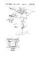
- FIG. 1is a side elevational view of a vehicle seat in accordance with the invention showing the seat in an untilted horizontal position;
- FIG. 1ais a fragmentary, exploded, perspective view of the pivotal, transverse mounting of the seat assembly shown in FIG. 1, on an enlarged scale;
- FIG. 2is a fragmentary view similar to that of FIG. 1 but showing the seat in a full tilted position;
- FIG. 3is a rear elevational view of a portion of the vehicle seat shown in FIG. 1 showing a tilt lock assembly according to the present invention
- FIG. 3ais a fragmentary, rear elevational view of a portion of the assembly shown in FIG. 3;
- FIG. 4is a side elevational view of the tilt lock assembly showing the seat in an untilted or normal position and with the lock assembly released;
- FIG. 5is a fragmentary top view of a portion of the seat assembly taken along line V--V of FIG. 1;
- FIG. 6is a fragmentary side elevational view of a portion of the tilt lock assembly shown in FIG. 4, but on an enlarged scale and with parts broken away for clarity;
- FIG. 7is an exploded view of a front portion of the seat assembly shown in FIGS. 1, 8 and 9, and showing the improved seat rake adjustment assembly;
- FIG. 8is a cross-sectional side elevational view of the seat rake adjustment assembly in a fully retracted position
- FIG. 9is a view similar to FIG. 8 but showing the seat rake adjustment assembly in a fully raised position
- FIG. 10is a front elevational view of the seat rake adjustment, the view being taken along line 10--10 in FIG. 8;
- FIG. 11is a side elevational view of a backhoe digging an excavation and where the invention finds particular utility.
- FIG. 12is a schematic view of an operator in the backhoe and indicating his line of sight into the excavation.
- the improved vehicle seatfinds particular utility when used in the environment shown in FIG. 11.
- the improved apparatusincludes a seat assembly 10 (FIG. 1), a suspension assembly 11, and a tilt lock assembly 12, all mounted on a pedestal support 13.
- the pedestal support 13is secured to a platform or floor 14 of a vehicle such as an earth working backhoe.
- the seat assemblycomprises a rigid sheet metal seat pan 15 formed to provide a backrest portion 16 and a seat portion 17.
- a seat cushion of shaped or contoured layers or blocks 18 and 19 of resilient compressible material, such as foam, sponge rubber or the like,are fixed upon the seat portion 17 and the backrest portion 16, respectively, of the seat pan 15.
- Flexible exterior upholstery covers 20 and 21 of vinyl fabric or the likeare secured around blocks 18 and 19, respectively.
- An edging or finishing strip 22(FIGS. 8 and 9) secures the cover to the seat pan 15.
- the seat assembly 10is resiliently supported for vertical motion by means of the suspension assembly 11 which comprises a rigid support frame 23 having a pair of laterally spaced apart side plates 24 and 25 secured to the bottom of the support frame 23.
- the support frame 23is positioned behind the backrest portion 16 of the seat assembly 10 and is also secured to the seat assembly 10 by means of a pair of tie rods 26 (FIG. 1a).
- the tie rods 26are rigidly secured together at their forward ends by a cross tube 26a.
- the rear ends of the rods 26are rigidly connected together by a cross shaft 26b.
- Shaft 26bis supported on the stationary frame 23.
- the tube 26ais connected by pin 28 to bracket 27.
- Bracket 27is secured to the center of the bottom of the seat portion 17 by bolts 29.
- the support frame 23houses suspension assembly 11 and a shock absorber 30, all of which is shown in the said U.S. patent application Ser. No. 384,035.
- the seat assembly 10is operably connected to the suspension apparatus by means of formed bracket 31 (FIGS. 1, 1a, 2) secured to the back of the backrest portion 16 of the seat pan 15 and secured to the suspension apparatus within the support frame 23. Screw adjustment means 23a are provided for adjusting the compression of the two springs 24a.
- the suspension apparatuspermits vertical motion of the seat (relative to the support frame 23) which is dampened to absorb shocks and provide comfort for a seat occupant.
- Such a suspension assembly 11is described more fully in commonly assigned and co-pending U.S. patent application Ser. No. 384,035.
- the pedestal 13, secured to the floor 14,is a swivel pedestal such as is more fully described in commonly assigned U.S. Pat. No. 4,014,507. It is believed sufficient to say that the pedestal 13 includes a pair of laterally spaced apart slide tubes 32 (only one shown); a pair of laterally spaced apart top rails 33 which are fixed to tubes 32 which in turn are slidably engaged in guide tubes 32a of the riser assembly. Accordingly, the suspension assembly 11 and, hence, the seat assembly 10 which is attached to the suspension assembly 11 may be moved rearward or forward by moving the top rails 33 (FIG. 1) along with the slide tubes 32 since the suspension assembly 11 is secured to the top rails 33 in a manner which will now be described.
- a rigid metal support plate 34is provided extending between and resting upon the top rails 33 of the pedestal 13.
- the support plate 34is suitably secured, such as by bolts 35, to the top rails 33 to permit the support plate 34 to ride with the top rails 33 and slide tubes 32 as it slides in the guide tubes 32a.
- the support frame 23 of the suspension assembly 11is pivotally secured to the support plate 34 by a pair of laterally spaced mounting brackets 36 (FIGS. 1, 1a, 2, 4 and 5) and rigid support braces 37 pivoted thereto.
- the mounting brackets 36are welded to the support plate 34 and have axially aligned holes 40 which define the transverse pivotal axis X--X.
- the pivotal axis X--Xis beneath the center of gravity of an occupied seat and suspension assembly. This pivot axis permits the seat unit to tilt by the operator's weight shift and the operator's height does not significantly change.
- the support braces 37are welded to the side plates 24 and 25, respectively, of the support frame 23.
- the support braces 37extend from the side plates toward the mounting bracket 36 and terminate at its free end where it is pivoted to the brackets as mentioned.
- the suspension assembly 11 and the attached seat assembly 10may be pivoted about axis X--X to permit the seat assembly to be variably tilted relative to the support plate 34.
- the tilt lock assembly 12is provided to releasably lock the seat and suspension assemblies in a plurality of tilted positions.
- the lock assembly 12includes a U-shaped, stationary lock member comprising the support plate 34 and a pair of parallel laterally spaced apart side plates 50 and 51.
- the side plates 50 and 51are integrally formed with the support plate 34 and are spaced apart a distance sufficient to receive the support frame 23 of the suspension assembly and to permit unobstructed movement of the suspension assembly 11 as it rotates about pivotal axis X--X.
- the trailing or rear edges of side plates 50 and 51are arcuate to define a plurality of notches 52 along their rear edge.
- the notches 52 of plate 50are aligned with the notches 52 of plate 51 such that a common axis Y--Y extending between the notches is parallel with the support plate and, hence, with pivotal axis X--X.
- the tilt lock assembly 12also includes a movable lock bar 53 pivotally connected to the support frame 23, and is adapted to releasably engage the stationary lock member.
- a hinge bar 54is secured to the support frame 23 by mounting brackets 55 having axially aligned holes 57 to receive hinge bar 54.
- the axis of the hinge bar 54is parallel to the pivotal axis X--X.
- the lock bar 53is spaced from and swingably connected to the hinge bar 54 by means of the hinge plates 59.
- the bell-crank shaped hinge plates 59have an end 63 with holes 64 which rotatably receive the lock bar 53.
- the hinge plates 59are sized such that the lock bar 53 is retained parallel to the pivotal axis X--X.
- the lock bar 53is of axial dimension sufficient to extend past the side plates 50 and 51 of the stationary lock member and sized to be selectively received within aligned notches 52.
- a handle 65is provided on one outer end of the lock bar 53 and extends along the exterior of the left side plate 50 of the stationary lock member.
- a pair of springs 66are provided on the left and right side plates of the suspension assembly support frame and are connected between the side plates and the hinge plates to bias the latter to the locking position of the bar 53.
- a pair of stop pins 67 provided on brackets 55limit rearward travel of bell-cranks 59.
- a seat occupantmay selectively vary the tilt position of the seat assembly 10.
- the seat assembly 10is shown in a first, or untilted position, the lock bar 53 being received within the lowermost notches of the side plates 50 and 51 with the springs 66 urging the lock bar 53 within the notches and securing the seat assembly in the position shown.
- An occupantmay unlock the tilt lock mechanism by engaging the handle 65 and moving the lock bar 53, against the bias of the springs, out of the lock position to a release position as shown in FIG. 4 where the lock bar 53 is clear the side plate notches.
- the seat assembly 10With the lock bar 53 in the release position, the seat assembly 10 is now freely rotatable about the axis X--X and may be rotated to a desired tilt position, for example, a maximum downward tilt position as shown in FIG. 2, where it can again be locked in position.
- the entire tilt adjust apparatustogether with the suspension assembly 11, can be tilted about axis X--X and the suspension assembly remains operative in any tilted position of the seat assembly.
- the desired degree of tilt of the seatcan be easily obtained by a slight shifting of the operator's weight.
- the pivot pointis directly under the center of gravity of the combined weight of the suspension assembly and the operator. This results in no appreciable change in height of the operator.
- the seat pan 15is provided with a generally flat seat portion 17 having a recessed portion 70 centrally located along the leading edge of the seat pan 15.
- the recessed portionis defined in part by a generally flat floor portion 75.
- a seat rake adjustmentincludes a pair of laterally spaced apart, notched brackets 77 which are welded as at 78 to the rake adjustment pan 76 pivoted at 74 to the seat portion 17.
- An apertureis formed in each of the brackets and defines a lower notch 80, an intermediate notch 81 and an upper notch 82.
- a hook latch 85has a lower hook portion 86 which extends through an aperture in the floor portion 75 and its upper end has laterally extending ears 88 which can be selectively engaged by the notches in the brackets. As shown in FIG. 9, the hook latch is engaged in the lower notch 80 so as to position the seat edge in the upper position.
- the upper end of the hook latchis engaged in the upper end of the upper notch 82 and in that position the seat edge is in the lowermost position.
- the hook latchis adjusted through the handle 90 which has a curved portion 91 that fits over and is retained by a shaft 92 which in turn extends through aligned apertures in the bracket 77 and is held captive therein by the locking rings 93 engaged in each end of the shaft 92.
- the forward end 94 of the handlecan be pulled upwardly by the operator which causes the lower end 95 of the handle to be pulled away from the hook latch, thereby permitting the plate spring 97 to urge the hook latch ears into the notches of the brackets 77.
- the operatorwishes to adjust the front edge of the seat to an upward position as shown in FIG.
- the seat rake adjustmentcompensates for the seat tilting and provides adequate but not undue thigh pressure and ergonomic thigh and back angles of the operator.
- the resultis a secure and supportive seat station in any of the tilted positions.
- the eye position and line of sight of the operatoris translated over the work area (FIG. 12) without translating the position of the seat a corresponding amount, resulting in minimizing the possibility of interference with the controls or pinch points.
Landscapes
- Engineering & Computer Science (AREA)
- Aviation & Aerospace Engineering (AREA)
- Transportation (AREA)
- Mechanical Engineering (AREA)
- Mining & Mineral Resources (AREA)
- Civil Engineering (AREA)
- General Engineering & Computer Science (AREA)
- Structural Engineering (AREA)
- Seats For Vehicles (AREA)
Abstract
Description
Claims (8)
Priority Applications (6)
| Application Number | Priority Date | Filing Date | Title |
|---|---|---|---|
| US06/523,783US4561621A (en) | 1983-08-17 | 1983-08-17 | Tiltable vehicle seat for backhoes or the like |
| CA000458082ACA1217704A (en) | 1983-08-17 | 1984-07-04 | Tiltable vehicle seat for backhoes or the like |
| FR8411312AFR2550740B1 (en) | 1983-08-17 | 1984-07-17 | RECLINING VEHICLE SEAT FOR EXCAVATING MECHANICAL EXCAVATORS OR OTHER EQUIPMENT OF THIS TYPE |
| GB08418555AGB2144983B (en) | 1983-08-17 | 1984-07-20 | Tiltable vehicle seat |
| DE19843428960DE3428960A1 (en) | 1983-08-17 | 1984-08-06 | TILTABLE VEHICLE SEAT FOR A DEFLECTOR EXCAVATOR OR THE LIKE. MACHINE |
| GB08605883AGB2170701B (en) | 1983-08-17 | 1986-03-10 | Rake adjustment means for tiltable vehicle seat |
Applications Claiming Priority (1)
| Application Number | Priority Date | Filing Date | Title |
|---|---|---|---|
| US06/523,783US4561621A (en) | 1983-08-17 | 1983-08-17 | Tiltable vehicle seat for backhoes or the like |
Publications (1)
| Publication Number | Publication Date |
|---|---|
| US4561621Atrue US4561621A (en) | 1985-12-31 |
Family
ID=24086446
Family Applications (1)
| Application Number | Title | Priority Date | Filing Date |
|---|---|---|---|
| US06/523,783Expired - LifetimeUS4561621A (en) | 1983-08-17 | 1983-08-17 | Tiltable vehicle seat for backhoes or the like |
Country Status (5)
| Country | Link |
|---|---|
| US (1) | US4561621A (en) |
| CA (1) | CA1217704A (en) |
| DE (1) | DE3428960A1 (en) |
| FR (1) | FR2550740B1 (en) |
| GB (2) | GB2144983B (en) |
Cited By (23)
| Publication number | Priority date | Publication date | Assignee | Title |
|---|---|---|---|---|
| US4648655A (en)* | 1984-09-28 | 1987-03-10 | Jmh Holdings Limited | Vehicle seats |
| US4836609A (en)* | 1988-04-18 | 1989-06-06 | Milsco Manufacturing Company | Vehicle seat |
| US4890887A (en)* | 1989-03-06 | 1990-01-02 | Sears Manufacturing Company | Suspension seat for vehicles with restricted operator environment |
| US5039054A (en)* | 1989-12-29 | 1991-08-13 | I Pai | Safe height-adjusting device |
| US5367978A (en)* | 1992-08-05 | 1994-11-29 | Mardikian 1991 Irrevocable Trust | Shock-absorber mounted seat for personal watercraft and boats |
| US5390979A (en)* | 1988-05-23 | 1995-02-21 | British Technology Group Ltd. | Adjustable chair |
| US5507550A (en)* | 1994-06-06 | 1996-04-16 | Hasbro, Inc. | Highchair |
| US5522645A (en)* | 1994-04-01 | 1996-06-04 | Milsco Manufacturing Company | Seat having retained cushion |
| US5538326A (en)* | 1994-11-14 | 1996-07-23 | Milsco Manufacturing Company | Flexible unitary seat shell |
| US6007150A (en)* | 1998-03-08 | 1999-12-28 | Milsco Manufacturing Company | Motorcycle seat with adjustable backrest |
| US6089653A (en)* | 1997-09-26 | 2000-07-18 | The First Years Inc. | Adjustable high chair and carrier |
| US20040144906A1 (en)* | 2002-11-15 | 2004-07-29 | Milsco Manufacturing, A Unit Of Jason Inc. | Vehicle seat suspension and method |
| GB2412060A (en)* | 2004-03-18 | 2005-09-21 | Sunpex Technology Co Ltd | Angular adjustment device for motorised wheelchair seat |
| GB2425721A (en)* | 2005-05-04 | 2006-11-08 | Nmi Safety Systems Ltd | Vehicle seat with lateral and rotational movement with detachable squab |
| US20070029857A1 (en)* | 2005-07-14 | 2007-02-08 | Hanson Wayne H | Adjustable motion wheel chair |
| US20090015040A1 (en)* | 2006-09-23 | 2009-01-15 | Dean Redmann | Universally Adjustable Swivel Chair |
| US20090127908A1 (en)* | 2007-10-04 | 2009-05-21 | John Kucharski | Seat Swivel Mechanism |
| US20090322132A1 (en)* | 2008-06-25 | 2009-12-31 | Wonderland Nurserygoods Co., Ltd. | Car seat |
| US20150115126A1 (en)* | 2013-10-31 | 2015-04-30 | Sears Manufacturing Co. | Rear Mounted Vehicle Seat Suspension |
| US9428276B1 (en) | 2015-02-19 | 2016-08-30 | PAC Seating Systems, Inc. | Swivel mechanism for vehicle seat |
| US9718382B2 (en) | 2014-10-02 | 2017-08-01 | Bose Corporation | Seat suspension |
| CN112962708A (en)* | 2021-04-07 | 2021-06-15 | 雷沃工程机械集团有限公司 | Excavator armrest box complete set mechanism |
| IT202300010302A1 (en)* | 2023-05-22 | 2024-11-22 | Amog S R L | VISIBILITY IMPROVEMENT SYSTEM IN WORK VEHICLES |
Families Citing this family (5)
| Publication number | Priority date | Publication date | Assignee | Title |
|---|---|---|---|---|
| DE8500390U1 (en)* | 1985-01-09 | 1985-04-04 | Steifensand Sitzmöbel- und Tischfabrik Inh.: F. Martin Steifensand, 8501 Wendelstein | CHAIR OR ARMCHAIR |
| AU7981287A (en)* | 1987-06-09 | 1988-12-15 | Super Sagless Corporation | Reclining chair |
| US5176356A (en)* | 1991-11-27 | 1993-01-05 | Milsco Manufacturing Company | Seat suspension with quick height adjustment |
| DE29518853U1 (en)* | 1995-10-13 | 1997-02-13 | Mohr, Ernst, Dipl.-Ing., Murten | Seat arrangement for passenger vehicles or the like. |
| DE202007003820U1 (en)* | 2007-03-08 | 2008-07-10 | Brose Fahrzeugteile Gmbh & Co. Kommanditgesellschaft, Coburg | Assembly for a vehicle seat with an adjusting device for adjusting an adjustment |
Citations (17)
| Publication number | Priority date | Publication date | Assignee | Title |
|---|---|---|---|---|
| US1788113A (en)* | 1927-10-19 | 1931-01-06 | Indian Splint Inc | Latch mechanism for reclining chairs |
| US1855245A (en)* | 1931-01-05 | 1932-04-26 | Checker Cab Mfg Corp | Adjustable seat |
| FR787687A (en)* | 1935-03-21 | 1935-09-26 | Improvements to tilting seats | |
| US2292414A (en)* | 1941-01-28 | 1942-08-11 | Forest C Vernon | Upholstered adjustable chair |
| AT207701B (en)* | 1958-10-20 | 1960-02-25 | Traktorenwerk Schoenebeck Veb | Suspended driver's seat for agricultural tractors |
| US3304044A (en)* | 1965-03-29 | 1967-02-14 | Deere & Co | Vehicle seat structure |
| US3741511A (en)* | 1971-06-01 | 1973-06-26 | G Streeter | Seat tilting structure |
| GB1384746A (en)* | 1972-03-20 | 1975-02-19 | Sifra | Suspension device for automotive vehicle seat |
| US3975050A (en)* | 1975-05-14 | 1976-08-17 | Mckee Dale P | Tilting swivel chair support |
| DE2546883A1 (en)* | 1975-10-20 | 1977-04-21 | Isringhausen Geb | Dampened driving seat for construction vehicle - with suspension inclined forwards to absorb horizontal and vertical vibrations |
| US4089499A (en)* | 1972-02-18 | 1978-05-16 | Dunlop Limited | Seats |
| US4155593A (en)* | 1978-03-20 | 1979-05-22 | Milsco Manufacturing Company | Vehicle seat having seat rake adjustment means |
| US4168050A (en)* | 1977-08-31 | 1979-09-18 | Winnebago Industries, Inc. | Tiltable swivel seat |
| US4304384A (en)* | 1978-09-23 | 1981-12-08 | Keiper Automobiltechnik Gmbh & Co. Kg | Device for adjusting inclined position of seats, particularly motor vehicle seats |
| FR2508298A1 (en)* | 1981-06-26 | 1982-12-31 | Toyota Motor Co Ltd | DEVICE FOR ADJUSTING THE HEIGHT OF THE FRONTAL PART OF THE CUSHION OF A SEAT |
| US4384741A (en)* | 1977-10-29 | 1983-05-24 | Christof Stoll Gmbh & Co. Kg | Tilting device for seating units |
| US4385743A (en)* | 1979-08-16 | 1983-05-31 | Keiper Automobiltechnik Gmbh & Co. Kg | Frame for a longitudinally and height-adjustable vehicle seat |
Family Cites Families (5)
| Publication number | Priority date | Publication date | Assignee | Title |
|---|---|---|---|---|
| GB809087A (en)* | 1956-07-02 | 1959-02-18 | J B Brooks Ind Ltd | Improvements in saddles and seats |
| GB927069A (en)* | 1960-12-29 | 1963-05-22 | Clark Equipment Co | Seat suspension |
| US3412968A (en)* | 1967-02-20 | 1968-11-26 | Massey Ferguson Inc | Multiple position vehicle seat assembly |
| US4014507A (en)* | 1976-01-12 | 1977-03-29 | Milsco Manufacturing Company | Seat supporting assembly |
| SE413649B (en)* | 1977-01-24 | 1980-06-16 | Saab Scania Ab | DEVICE FOR ATTEMPTING TURNING MOVEMENTS AT VEHICLES |
- 1983
- 1983-08-17USUS06/523,783patent/US4561621A/ennot_activeExpired - Lifetime
- 1984
- 1984-07-04CACA000458082Apatent/CA1217704A/ennot_activeExpired
- 1984-07-17FRFR8411312Apatent/FR2550740B1/ennot_activeExpired
- 1984-07-20GBGB08418555Apatent/GB2144983B/ennot_activeExpired
- 1984-08-06DEDE19843428960patent/DE3428960A1/enactiveGranted
- 1986
- 1986-03-10GBGB08605883Apatent/GB2170701B/ennot_activeExpired
Patent Citations (17)
| Publication number | Priority date | Publication date | Assignee | Title |
|---|---|---|---|---|
| US1788113A (en)* | 1927-10-19 | 1931-01-06 | Indian Splint Inc | Latch mechanism for reclining chairs |
| US1855245A (en)* | 1931-01-05 | 1932-04-26 | Checker Cab Mfg Corp | Adjustable seat |
| FR787687A (en)* | 1935-03-21 | 1935-09-26 | Improvements to tilting seats | |
| US2292414A (en)* | 1941-01-28 | 1942-08-11 | Forest C Vernon | Upholstered adjustable chair |
| AT207701B (en)* | 1958-10-20 | 1960-02-25 | Traktorenwerk Schoenebeck Veb | Suspended driver's seat for agricultural tractors |
| US3304044A (en)* | 1965-03-29 | 1967-02-14 | Deere & Co | Vehicle seat structure |
| US3741511A (en)* | 1971-06-01 | 1973-06-26 | G Streeter | Seat tilting structure |
| US4089499A (en)* | 1972-02-18 | 1978-05-16 | Dunlop Limited | Seats |
| GB1384746A (en)* | 1972-03-20 | 1975-02-19 | Sifra | Suspension device for automotive vehicle seat |
| US3975050A (en)* | 1975-05-14 | 1976-08-17 | Mckee Dale P | Tilting swivel chair support |
| DE2546883A1 (en)* | 1975-10-20 | 1977-04-21 | Isringhausen Geb | Dampened driving seat for construction vehicle - with suspension inclined forwards to absorb horizontal and vertical vibrations |
| US4168050A (en)* | 1977-08-31 | 1979-09-18 | Winnebago Industries, Inc. | Tiltable swivel seat |
| US4384741A (en)* | 1977-10-29 | 1983-05-24 | Christof Stoll Gmbh & Co. Kg | Tilting device for seating units |
| US4155593A (en)* | 1978-03-20 | 1979-05-22 | Milsco Manufacturing Company | Vehicle seat having seat rake adjustment means |
| US4304384A (en)* | 1978-09-23 | 1981-12-08 | Keiper Automobiltechnik Gmbh & Co. Kg | Device for adjusting inclined position of seats, particularly motor vehicle seats |
| US4385743A (en)* | 1979-08-16 | 1983-05-31 | Keiper Automobiltechnik Gmbh & Co. Kg | Frame for a longitudinally and height-adjustable vehicle seat |
| FR2508298A1 (en)* | 1981-06-26 | 1982-12-31 | Toyota Motor Co Ltd | DEVICE FOR ADJUSTING THE HEIGHT OF THE FRONTAL PART OF THE CUSHION OF A SEAT |
Cited By (31)
| Publication number | Priority date | Publication date | Assignee | Title |
|---|---|---|---|---|
| US4648655A (en)* | 1984-09-28 | 1987-03-10 | Jmh Holdings Limited | Vehicle seats |
| US4836609A (en)* | 1988-04-18 | 1989-06-06 | Milsco Manufacturing Company | Vehicle seat |
| US5390979A (en)* | 1988-05-23 | 1995-02-21 | British Technology Group Ltd. | Adjustable chair |
| US4890887A (en)* | 1989-03-06 | 1990-01-02 | Sears Manufacturing Company | Suspension seat for vehicles with restricted operator environment |
| US5039054A (en)* | 1989-12-29 | 1991-08-13 | I Pai | Safe height-adjusting device |
| US5367978A (en)* | 1992-08-05 | 1994-11-29 | Mardikian 1991 Irrevocable Trust | Shock-absorber mounted seat for personal watercraft and boats |
| US5522645A (en)* | 1994-04-01 | 1996-06-04 | Milsco Manufacturing Company | Seat having retained cushion |
| US5507550A (en)* | 1994-06-06 | 1996-04-16 | Hasbro, Inc. | Highchair |
| US5538326A (en)* | 1994-11-14 | 1996-07-23 | Milsco Manufacturing Company | Flexible unitary seat shell |
| US5599069A (en)* | 1994-11-14 | 1997-02-04 | Milsco Manufacturing Company | Flexible unitary seat shell including base section having frame sockets |
| US6089653A (en)* | 1997-09-26 | 2000-07-18 | The First Years Inc. | Adjustable high chair and carrier |
| US6007150A (en)* | 1998-03-08 | 1999-12-28 | Milsco Manufacturing Company | Motorcycle seat with adjustable backrest |
| US20040144906A1 (en)* | 2002-11-15 | 2004-07-29 | Milsco Manufacturing, A Unit Of Jason Inc. | Vehicle seat suspension and method |
| US7185867B2 (en) | 2002-11-15 | 2007-03-06 | Milsco Manufacturing Company, A Unit Of Jason Incorporated | Vehicle seat suspension and method |
| GB2412060A (en)* | 2004-03-18 | 2005-09-21 | Sunpex Technology Co Ltd | Angular adjustment device for motorised wheelchair seat |
| GB2425721A (en)* | 2005-05-04 | 2006-11-08 | Nmi Safety Systems Ltd | Vehicle seat with lateral and rotational movement with detachable squab |
| US20060250011A1 (en)* | 2005-05-04 | 2006-11-09 | Nmi Safety Systems Ltd. | Vehicle fitting |
| US20070029857A1 (en)* | 2005-07-14 | 2007-02-08 | Hanson Wayne H | Adjustable motion wheel chair |
| US7455362B2 (en)* | 2005-07-14 | 2008-11-25 | Kids Up, Inc. | Adjustable motion wheel chair |
| US7717514B2 (en)* | 2006-09-23 | 2010-05-18 | Dean Redmann | Universally adjustable swivel chair |
| US20090015040A1 (en)* | 2006-09-23 | 2009-01-15 | Dean Redmann | Universally Adjustable Swivel Chair |
| US20090127908A1 (en)* | 2007-10-04 | 2009-05-21 | John Kucharski | Seat Swivel Mechanism |
| US20090322132A1 (en)* | 2008-06-25 | 2009-12-31 | Wonderland Nurserygoods Co., Ltd. | Car seat |
| US8083290B2 (en)* | 2008-06-25 | 2011-12-27 | Wonderland Nurserygoods Co., Ltd. | Car seat |
| US20150115126A1 (en)* | 2013-10-31 | 2015-04-30 | Sears Manufacturing Co. | Rear Mounted Vehicle Seat Suspension |
| US9469227B2 (en)* | 2013-10-31 | 2016-10-18 | Sears Manufacturing Co. | Rear mounted vehicle seat suspension |
| US9718382B2 (en) | 2014-10-02 | 2017-08-01 | Bose Corporation | Seat suspension |
| US9428276B1 (en) | 2015-02-19 | 2016-08-30 | PAC Seating Systems, Inc. | Swivel mechanism for vehicle seat |
| CN112962708A (en)* | 2021-04-07 | 2021-06-15 | 雷沃工程机械集团有限公司 | Excavator armrest box complete set mechanism |
| CN112962708B (en)* | 2021-04-07 | 2023-12-12 | 雷沃工程机械集团有限公司 | Complete set of mechanism of excavator armrest box |
| IT202300010302A1 (en)* | 2023-05-22 | 2024-11-22 | Amog S R L | VISIBILITY IMPROVEMENT SYSTEM IN WORK VEHICLES |
Also Published As
| Publication number | Publication date |
|---|---|
| GB2170701A (en) | 1986-08-13 |
| CA1217704A (en) | 1987-02-10 |
| FR2550740A1 (en) | 1985-02-22 |
| GB8605883D0 (en) | 1986-04-16 |
| DE3428960A1 (en) | 1985-03-07 |
| GB2144983A (en) | 1985-03-20 |
| DE3428960C2 (en) | 1990-10-04 |
| FR2550740B1 (en) | 1989-01-20 |
| GB2170701B (en) | 1987-02-11 |
| GB2144983B (en) | 1987-02-11 |
| GB8418555D0 (en) | 1984-08-22 |
Similar Documents
| Publication | Publication Date | Title |
|---|---|---|
| US4561621A (en) | Tiltable vehicle seat for backhoes or the like | |
| GB2118031A (en) | Vehicle seats | |
| US5246271A (en) | Vehicle seats with built-in safety belt | |
| US3632166A (en) | Vehicle seat having combined contour and tilt adjustment | |
| US5810436A (en) | Child seat with a tiltable back | |
| US4616874A (en) | Vehicle seat assembly | |
| US4141586A (en) | Vehicle seat | |
| US4533110A (en) | Resiliently suspended, tiltable and tethered vehicle operator's seat having fore and aft adjustment | |
| US4269446A (en) | Displaceable seat for automotive vehicles | |
| US5193880A (en) | Chair, in particular work or office chair | |
| US5433509A (en) | Adjustable armrest | |
| US3893728A (en) | Material handling apparatus | |
| EP0987968A1 (en) | Operator-interactive adjustable workstation | |
| GB2098935A (en) | Collapsible wheelchair for a disabled person | |
| US5429414A (en) | Relating to a child seat | |
| US3448820A (en) | Vehicle seat structure | |
| GB1595633A (en) | Seat support assembly for a vehicle | |
| US3437373A (en) | Seat assembly | |
| US4593875A (en) | Tethered vehicle operator's seat having wide range of fore and aft adjustment | |
| US4072343A (en) | Reversible and adjustable bilevel seat for dual-purpose vehicle | |
| US4458941A (en) | Two position seat assembly | |
| GB1595625A (en) | Vehicle seat | |
| US3347512A (en) | Locking device for adjustable vehicle seats | |
| US3977644A (en) | Seat construction | |
| US4252368A (en) | Dual seat for material handling equipment |
Legal Events
| Date | Code | Title | Description |
|---|---|---|---|
| AS | Assignment | Owner name:MILSCO MANUFACTURING COMPANY, MILWAUKEE, WISCONSIN Free format text:ASSIGNMENT OF ASSIGNORS INTEREST.;ASSIGNOR:HILL, KEVIN E.;REEL/FRAME:004463/0764 Effective date:19830805 Owner name:MILSCO MANUFACTURING COMPANY, A CORP OF WISCONSIN, Free format text:ASSIGNMENT OF ASSIGNORS INTEREST;ASSIGNOR:HILL, KEVIN E.;REEL/FRAME:004463/0764 Effective date:19830805 | |
| STCF | Information on status: patent grant | Free format text:PATENTED CASE | |
| FEPP | Fee payment procedure | Free format text:PAYOR NUMBER ASSIGNED (ORIGINAL EVENT CODE: ASPN); ENTITY STATUS OF PATENT OWNER: LARGE ENTITY | |
| FPAY | Fee payment | Year of fee payment:4 | |
| FPAY | Fee payment | Year of fee payment:8 | |
| AS | Assignment | Owner name:FIRST NATIONAL BANK OF CHICAGO, THE, ILLINOIS Free format text:THIRD AMENDMENT TO PATENT AND LICENSE SECURITY AGREEMENT;ASSIGNOR:JASON INCORPORATED;REEL/FRAME:007289/0398 Effective date:19950103 | |
| AS | Assignment | Owner name:JASON, INCORPORATED, WISCONSIN Free format text:ASSIGNMENT OF ASSIGNORS INTEREST;ASSIGNOR:MILSCO MANUFACTURING COMPANY;REEL/FRAME:007388/0433 Effective date:19950103 | |
| FEPP | Fee payment procedure | Free format text:PAT HLDR NO LONGER CLAIMS SMALL ENT STAT AS SMALL BUSINESS (ORIGINAL EVENT CODE: LSM2); ENTITY STATUS OF PATENT OWNER: LARGE ENTITY | |
| FPAY | Fee payment | Year of fee payment:12 | |
| AS | Assignment | Owner name:CREDIT AGRICOLE INDOSUEZ, AS COLLATERAL AGENT, NEW Free format text:SECURITY AGREEMENT;ASSIGNOR:JASON INCORPORATED;REEL/FRAME:011035/0280 Effective date:20000804 | |
| AS | Assignment | Owner name:JASON INCORPORATED, WISCONSIN Free format text:TERMINATION OF SECURITY INTEREST (FIRST LIEN);ASSIGNOR:CALYON, AS AGENT (AS SUCCESSOR BY MERGER TO CREDIT AGRICOLE INDOSUEZ);REEL/FRAME:017145/0733 Effective date:20051216 | |
| AS | Assignment | Owner name:JASON INCORPORATED, WISCONSIN Free format text:TERMINATION OF SECURITY INTEREST (SECOND LIEN);ASSIGNOR:CALYON, AS AGENT (AS SUCCESSOR BY MERGER TO CREDIT AGRICOLE INDOSUEZ);REEL/FRAME:017136/0901 Effective date:20051216 | |
| AS | Assignment | Owner name:JASON INCORPORATED, WISCONSIN Free format text:RELEASE BY SECURED PARTY;ASSIGNOR:THE FIRST NATIONAL BANK OF CHICAGO;REEL/FRAME:025320/0665 Effective date:20000816 |