US4561204A - Reticle display for small arms - Google Patents
Reticle display for small armsDownload PDFInfo
- Publication number
- US4561204A US4561204AUS06/511,096US51109683AUS4561204AUS 4561204 AUS4561204 AUS 4561204AUS 51109683 AUS51109683 AUS 51109683AUS 4561204 AUS4561204 AUS 4561204A
- Authority
- US
- United States
- Prior art keywords
- reticle
- eye
- sighting
- screen
- target
- Prior art date
- Legal status (The legal status is an assumption and is not a legal conclusion. Google has not performed a legal analysis and makes no representation as to the accuracy of the status listed.)
- Expired - Fee Related
Links
- 238000005259measurementMethods0.000description5
- 238000012937correctionMethods0.000description2
- 230000000694effectsEffects0.000description2
- 238000012986modificationMethods0.000description2
- 230000004048modificationEffects0.000description2
- 241000282994CervidaeSpecies0.000description1
- 230000009471actionEffects0.000description1
- 230000008859changeEffects0.000description1
- 238000010586diagramMethods0.000description1
- 238000010304firingMethods0.000description1
- 239000004973liquid crystal related substanceSubstances0.000description1
- 239000011159matrix materialSubstances0.000description1
- 230000007246mechanismEffects0.000description1
- 230000000153supplemental effectEffects0.000description1
Images


Classifications
- F—MECHANICAL ENGINEERING; LIGHTING; HEATING; WEAPONS; BLASTING
- F41—WEAPONS
- F41G—WEAPON SIGHTS; AIMING
- F41G3/00—Aiming or laying means
- F41G3/06—Aiming or laying means with rangefinder
- F—MECHANICAL ENGINEERING; LIGHTING; HEATING; WEAPONS; BLASTING
- F41—WEAPONS
- F41G—WEAPON SIGHTS; AIMING
- F41G1/00—Sighting devices
- F41G1/38—Telescopic sights specially adapted for smallarms or ordnance; Supports or mountings therefor
- F—MECHANICAL ENGINEERING; LIGHTING; HEATING; WEAPONS; BLASTING
- F41—WEAPONS
- F41G—WEAPON SIGHTS; AIMING
- F41G1/00—Sighting devices
- F41G1/46—Sighting devices for particular applications
- F41G1/467—Sighting devices for particular applications for bows
- F—MECHANICAL ENGINEERING; LIGHTING; HEATING; WEAPONS; BLASTING
- F41—WEAPONS
- F41G—WEAPON SIGHTS; AIMING
- F41G3/00—Aiming or laying means
- F41G3/08—Aiming or laying means with means for compensating for speed, direction, temperature, pressure, or humidity of the atmosphere
Definitions
- the present inventionrelates to gun sights, and more particularly to a microprocessor controlled auxiliary reticle system adapted for use in conjunction with a telescopic sight for small arms, such as rifles and guns of like character.
- Computer controlled or computer assisted gun fire control systemsare, of course, well known, particularly in the field of military ordnance. These systems sense such ballistic factors as windage, relative humidity and temperature, and with additional inputs as to the type of ordnance used and target range, they provide appropriate information for ballistic superelevation and windage corrections. This information is then used to control the aiming of the gun, or to provide an appropriate deviation between the gun and a sighting device or sighting reticle.
- the principles of these gun fire control systemsare adapted to small arms, particularly rifles and guns of similar character. It is well known to provide a telescopic sight for a rifle, which may contain a cross-hairs reticle. The sight may be provided with a mechanical adjustment for changing the axis of the sight in elevation and azimuth relative to the axis of the rifle barrel, to accommodate for target range and windage. Thus, when properly set, if the cross-hairs reticle is aimed at the target, the bore of the gun will be offset by an amount that will cause the projectile to hit the target. Such devices are set mainly by guesswork and estimates, and require a great deal of skill
- the present inventionprovides a separate reticle display for use in combination with a telescopic gun sight, and is essentially an attachment to the telescopic sight, although it may be provided as an integrated adjunct to the telescopic sight.
- This reticle displaymay be generated on a liquid crystal diode (LCD), or a small cathode ray tube, or a dot matrix of light emitting diodes, or other analogous display device.
- LCDliquid crystal diode
- a microprocessoris incorporated with the reticle device to generate and position the reticle display. Windage, humidity and temperature sensors are provided as inputs to the microprocessor, along with a range measurement.
- the microprocessoradjusts the position of the reticle up or down and left or right on a display screen in accordance with these inputs and in accordance with previous calibrations introduced into the microprocessor, to effect a proper deviation between the line of sight to the target and the proper line of aim of the gun barrel to hit the target under the prevailing conditions.
- this reticle displayis presented separately from the telescopic sight, and may be an attachment to the sight. It is positioned so that the user, who may be, for example, a sportsman, a military marksman, or a target shooter, looks through the telescopic sight at the target field with his usual bore-axis eye, while simultaneously viewing the reticle display with his other eye. These two views are combined or superimposed by the user's mind into a single field of vision. The user then positions the rifle in elevation and azimuth until he sees the aiming reticle superposed on the target. Since the position of the aiming reticle on the display screen is adjusted in accordance with the ballistics and atmospheric conditions, when it is seen as superposed on the target, the rifle bore is pointed in the proper direction so the projectile will hit the target.
- Another object of the present inventionis to provide such a device that includes a microprocessor for adjusting the position of the aiming reticle display in accordance with various ballistic factors.
- Still another object of the present inventionis to provide such a device wherein the user views the reticle display with one eye, while viewing the target field through the telescopic sight with his other eye, providing a single field of vision of the reticle display superposed on the target field.
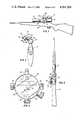
- FIG. 1is a side view of a rifle equipped with a telescopic sight and further having an opaque reticle attachment of the present invention
- FIG. 2is a rear view of the apparatus shown in FIG. 1;
- FIG. 3is a top plan view of the apparatus shown in FIG. 1;
- FIG. 4is an enlarged, fragmentary elevational view principally of the reticle display of FIG. 2;
- FIG. 5is a top plan view of the reticle attachment of FIG. 2 drawn to an enlarged scale
- FIG. 6is a right side elevational view of the reticle attachment of FIG. 5;
- FIG. 7is a functional block diagram illustrating the operation of the reticle display system of the present invention.
- a rifleis illustrated and indicated generally by the numeral 10.
- the rifleis provided with a conventional telescopic sight 12, mounted on the rifle at 14 and 16.
- the rifleis further provided with a reticle display tube, indicated generally by the numeral 18, which is offset from the telescopic sight 12 and extends generally parallel to the axis of the sight.
- reticle display tube 18also contains a microprocessor or microcomputer for positioning or locating the reticle display on the screen.
- the rear lens of telescope 12, designated 20, the opaque reticle display screen 22, and the spatial relation between these elements,is shown best in FIG. 2.
- tube 18is spaced or offset laterally from the telescopic sight 12 by an attachment bracket means 26.
- the attachment bracket 26has an adjustable clamp ring 27 which encircles the body of telescopic sight 12, so that the entire tube 18 may be orbited about the axis of the telescopic sight 12.
- the attachment bracket 26is shown at an angle of approximately 30 degrees relative to a horizontal line passing through the axis of the telescopic sight 12, and is in the general position for use by a right handed shooter who will use his right eye to sight through the telescopic sight 12 along the bore axis of the rifle, and will use his left eye to view the opaque reticle display face 22 of the reticle display tube 18.
- the reticle display tube 18would be orbited clockwise through approximately 120 degrees (as viewed in FIG. 2) to be in position for use by a left handed shooter. That is, a user who would look through the telescopic sight along the rifle bore axis with his left eye, would observe the opaque reticle display screen 22 of the reticle display tube 18 with his right eye.
- the arrow 30 in FIG. 2indicates that the length of bracket 26 is adjustable, such as by telescoping sections, so that the spacing of the reticle tube 18 from the telescopic sight 12 may be varied to compensate for differences in distances between the eyes of different users of the rifle. Once adjusted, the length of bracket 26 may be set by clamp 26a.
- the arrow 29indicates that the reticle display tube 18 is capable of being moved a limited amount along a line parallel to the axis of the telescopic sight by moving the clamp 27 along the body of the sight 12. The clamp 27 also affords the orbital adjustment previously mentioned, and indicated by the arrow 28.
- the arrow 31indicates that the axis of the display tube 18 may be adjustably tilted about the axis of the bracket 26 through the mechanism of clamp 26a.
- the screen 20may be accurately positioned to be properly viewed by the appropriate eye of the user.
- the display tube 18is just a housing and is not a sighting tube; functionally, the user simply sees the display generated on the opaque display screen 20.
- the atmospheric conditions transducersare illustrated, providing appropriate inputs to the microcomputer contained within the reticle tube 18.
- These transducersinclude Pitot tubes 36, 38 to measure cross wind velocity, Pitot tubes 46, 48 to measure frontrear wind velocity, an ambient temperature transducer shown at 40, and a relative humidity transducer at 42.
- a level transduceris shown in phantom at 54, to measure the angle of elevation of the rifle bore when sighted at the target.
- the specific forms of these transducersare, of course, well known in the gun fire control art, and therefore they are not shown in any significant detail herein.
- the measurements obtained from the transducersprovide the appropriate inputs to the microprocessor to compute the appropriate ballistic elevation and azimuth corrections necessary to effect correct aiming of the rifle, which is also well known in the gun fire control art.
- the primary displayscomprise the cross-hairs reticle 34, and the spaced lines range finder 32.
- the range finderis based on the spacing between the lines 32, which is adjustable by turning knob 24. Thus, turning of knob 24 changes the space between the lines 32, and simultaneously provides a corresponding range measurement input to the microprocessor.
- the userviews the target through the telescopic sight 12 with one eye, and views the display screen 22 with his other eye. As a result, the target image and the display screen are superposed or integrated in the user's vision.
- the range finderis initially callibrated in respect to some target aspect of nearly constant size, such as the bust of a man, or the bust of a deer.
- the constant size feature of the targetis framed between the lines 32 by enlarging or reducing the space therebetween through rotation of knob 24.
- the targetWhen properly framed, the target has been properly ranged, and that range data is inserted in the microprocessor.
- the microprocessorcomputes the necessary ballistic superelevation and azimuth deviation in view of the windage, the relative humidity, the temperature, and the line of sight elevation to the target.
- the resultant outputis used to position the cross-hairs reticle 34--e.g. downward as range is increased, to the right if windage is from the left, etc.
- the gunis aimed after the range is inserted by setting the spacing between the lines 32 as above described, the user positions the rifle so that in the combined vision of his two eyes, the cross-hairs reticle 34 appears positioned on the target. This action aims the rifle bore at that elevation and azimuth angle which will cause the fired projectile to strike the target.
- the values obtained for range and from the various transducers described abovecan be displayed on the screen 22, supplemental to the basic range finder and cross-hairs reticle display.
- the present inventioncan be marketed as a separate adjunct or accessory for use with many different rifles, and can be used for different ammunition. It is further apparent to those skilled in the art that accurate functioning of the reticle display system requires proper calibration. Obviously, the unit can be manufactured as an integral part of a specific rifle, and factory calibrated for that rifle and a specific type of ammunition.
- knobs 50 and 52are provided, which may be used to change and reset the position of the cross-hairs reticle display vertically and horizontally, as required, until perfect marksmanship is obtained under given conditions of firing and a given range setting. After calibration, new range measurements and changes in atmospheric conditions cause appropriate changes in the location of the cross-hairs reticle on the screen 22.
Landscapes
- Engineering & Computer Science (AREA)
- General Engineering & Computer Science (AREA)
- Physics & Mathematics (AREA)
- Optics & Photonics (AREA)
- Telescopes (AREA)
- Aiming, Guidance, Guns With A Light Source, Armor, Camouflage, And Targets (AREA)
Abstract
Description
The present invention relates to gun sights, and more particularly to a microprocessor controlled auxiliary reticle system adapted for use in conjunction with a telescopic sight for small arms, such as rifles and guns of like character.
Computer controlled or computer assisted gun fire control systems are, of course, well known, particularly in the field of military ordnance. These systems sense such ballistic factors as windage, relative humidity and temperature, and with additional inputs as to the type of ordnance used and target range, they provide appropriate information for ballistic superelevation and windage corrections. This information is then used to control the aiming of the gun, or to provide an appropriate deviation between the gun and a sighting device or sighting reticle.
In accordance with the present invention, the principles of these gun fire control systems are adapted to small arms, particularly rifles and guns of similar character. It is well known to provide a telescopic sight for a rifle, which may contain a cross-hairs reticle. The sight may be provided with a mechanical adjustment for changing the axis of the sight in elevation and azimuth relative to the axis of the rifle barrel, to accommodate for target range and windage. Thus, when properly set, if the cross-hairs reticle is aimed at the target, the bore of the gun will be offset by an amount that will cause the projectile to hit the target. Such devices are set mainly by guesswork and estimates, and require a great deal of skill
The present invention provides a separate reticle display for use in combination with a telescopic gun sight, and is essentially an attachment to the telescopic sight, although it may be provided as an integrated adjunct to the telescopic sight. This reticle display may be generated on a liquid crystal diode (LCD), or a small cathode ray tube, or a dot matrix of light emitting diodes, or other analogous display device. One LCD display of this general character is disclosed in U.S. Pat. No. 3,885,861 to Farnsworth et al. A microprocessor is incorporated with the reticle device to generate and position the reticle display. Windage, humidity and temperature sensors are provided as inputs to the microprocessor, along with a range measurement. The microprocessor adjusts the position of the reticle up or down and left or right on a display screen in accordance with these inputs and in accordance with previous calibrations introduced into the microprocessor, to effect a proper deviation between the line of sight to the target and the proper line of aim of the gun barrel to hit the target under the prevailing conditions.
As stated, this reticle display is presented separately from the telescopic sight, and may be an attachment to the sight. It is positioned so that the user, who may be, for example, a sportsman, a military marksman, or a target shooter, looks through the telescopic sight at the target field with his usual bore-axis eye, while simultaneously viewing the reticle display with his other eye. These two views are combined or superimposed by the user's mind into a single field of vision. The user then positions the rifle in elevation and azimuth until he sees the aiming reticle superposed on the target. Since the position of the aiming reticle on the display screen is adjusted in accordance with the ballistics and atmospheric conditions, when it is seen as superposed on the target, the rifle bore is pointed in the proper direction so the projectile will hit the target.
It is therefore one object of the present invention to provide a reticle display device for use with a small arms telescopic sight.
Another object of the present invention is to provide such a device that includes a microprocessor for adjusting the position of the aiming reticle display in accordance with various ballistic factors.
Still another object of the present invention is to provide such a device wherein the user views the reticle display with one eye, while viewing the target field through the telescopic sight with his other eye, providing a single field of vision of the reticle display superposed on the target field.
Other objects and the advantages of the present invention will become apparent to those skilled in the art from a consideration of the following detailed description of one illustrative embodiment of the invention.
The following detailed description of one embodiment of the invention is had in conjunction with the accompanying drawings, wherein like reference characters refer to like or corresponding parts, and wherein:
FIG. 1 is a side view of a rifle equipped with a telescopic sight and further having an opaque reticle attachment of the present invention;
FIG. 2 is a rear view of the apparatus shown in FIG. 1;
FIG. 3 is a top plan view of the apparatus shown in FIG. 1;
FIG. 4 is an enlarged, fragmentary elevational view principally of the reticle display of FIG. 2;
FIG. 5 is a top plan view of the reticle attachment of FIG. 2 drawn to an enlarged scale;
FIG. 6 is a right side elevational view of the reticle attachment of FIG. 5; and
FIG. 7 is a functional block diagram illustrating the operation of the reticle display system of the present invention.
Referring to FIG. 1 of the drawings, a rifle is illustrated and indicated generally by thenumeral 10. The rifle is provided with a conventionaltelescopic sight 12, mounted on the rifle at 14 and 16. The rifle is further provided with a reticle display tube, indicated generally by thenumeral 18, which is offset from thetelescopic sight 12 and extends generally parallel to the axis of the sight. However, aligning the reticle display tube with the telescopic sight is simply a matter of convenience, because the user does not sight through thetube 18, he only observes anopaque display screen 22 therein.Reticle display tube 18 also contains a microprocessor or microcomputer for positioning or locating the reticle display on the screen. The rear lens oftelescope 12, designated 20, the opaquereticle display screen 22, and the spatial relation between these elements, is shown best in FIG. 2.
Referring particularly to FIGS. 2 and 3, it will be seen thattube 18 is spaced or offset laterally from thetelescopic sight 12 by an attachment bracket means 26. Theattachment bracket 26 has anadjustable clamp ring 27 which encircles the body oftelescopic sight 12, so that theentire tube 18 may be orbited about the axis of thetelescopic sight 12. In the FIG. 2 position, theattachment bracket 26 is shown at an angle of approximately 30 degrees relative to a horizontal line passing through the axis of thetelescopic sight 12, and is in the general position for use by a right handed shooter who will use his right eye to sight through thetelescopic sight 12 along the bore axis of the rifle, and will use his left eye to view the opaquereticle display face 22 of thereticle display tube 18. Thereticle display tube 18 would be orbited clockwise through approximately 120 degrees (as viewed in FIG. 2) to be in position for use by a left handed shooter. That is, a user who would look through the telescopic sight along the rifle bore axis with his left eye, would observe the opaquereticle display screen 22 of thereticle display tube 18 with his right eye.
Thearrow 30 in FIG. 2 indicates that the length ofbracket 26 is adjustable, such as by telescoping sections, so that the spacing of thereticle tube 18 from thetelescopic sight 12 may be varied to compensate for differences in distances between the eyes of different users of the rifle. Once adjusted, the length ofbracket 26 may be set byclamp 26a. Similarly, in FIG. 1, thearrow 29 indicates that thereticle display tube 18 is capable of being moved a limited amount along a line parallel to the axis of the telescopic sight by moving theclamp 27 along the body of thesight 12. Theclamp 27 also affords the orbital adjustment previously mentioned, and indicated by thearrow 28. The arrow 31 indicates that the axis of thedisplay tube 18 may be adjustably tilted about the axis of thebracket 26 through the mechanism ofclamp 26a. Thus, as a result of the adjustments indicated byarrows screen 20 may be accurately positioned to be properly viewed by the appropriate eye of the user. It should be born in mind that thedisplay tube 18 is just a housing and is not a sighting tube; functionally, the user simply sees the display generated on theopaque display screen 20.
Referring to FIGS. 5 and 6, the atmospheric conditions transducers are illustrated, providing appropriate inputs to the microcomputer contained within thereticle tube 18. These transducers includePitot tubes Pitot tubes
Referring particularly to FIG. 4, the display appearing onscreen 22 is shown. The primary displays comprise thecross-hairs reticle 34, and the spacedlines range finder 32. The range finder is based on the spacing between thelines 32, which is adjustable by turningknob 24. Thus, turning ofknob 24 changes the space between thelines 32, and simultaneously provides a corresponding range measurement input to the microprocessor. As previously stated, the user views the target through thetelescopic sight 12 with one eye, and views thedisplay screen 22 with his other eye. As a result, the target image and the display screen are superposed or integrated in the user's vision. The range finder is initially callibrated in respect to some target aspect of nearly constant size, such as the bust of a man, or the bust of a deer. When the rifle sight is trained on a like subject, the constant size feature of the target is framed between thelines 32 by enlarging or reducing the space therebetween through rotation ofknob 24. When properly framed, the target has been properly ranged, and that range data is inserted in the microprocessor.
As the target range is introduced into the microprocessor in this manner, the microprocessor computes the necessary ballistic superelevation and azimuth deviation in view of the windage, the relative humidity, the temperature, and the line of sight elevation to the target. The resultant output is used to position thecross-hairs reticle 34--e.g. downward as range is increased, to the right if windage is from the left, etc. When the gun is aimed after the range is inserted by setting the spacing between thelines 32 as above described, the user positions the rifle so that in the combined vision of his two eyes, thecross-hairs reticle 34 appears positioned on the target. This action aims the rifle bore at that elevation and azimuth angle which will cause the fired projectile to strike the target.
If desired, the values obtained for range and from the various transducers described above, can be displayed on thescreen 22, supplemental to the basic range finder and cross-hairs reticle display.
It is apparent that the present invention can be marketed as a separate adjunct or accessory for use with many different rifles, and can be used for different ammunition. It is further apparent to those skilled in the art that accurate functioning of the reticle display system requires proper calibration. Obviously, the unit can be manufactured as an integral part of a specific rifle, and factory calibrated for that rifle and a specific type of ammunition. For user calibration, knobs 50 and 52 are provided, which may be used to change and reset the position of the cross-hairs reticle display vertically and horizontally, as required, until perfect marksmanship is obtained under given conditions of firing and a given range setting. After calibration, new range measurements and changes in atmospheric conditions cause appropriate changes in the location of the cross-hairs reticle on thescreen 22.
Having thus described one specific illustrative embodiment of the invention, it is understood that various modifications and variations will be apparent to those skilled in the art. Such modifications or variations as are embraced by the spirit and scope of the appended claims are contemplated as being within the purview of the present invention. For example, a particular form of range finder is illustrated in the specification operating in conjunction with the display screen and telescopic sight. Obviously, an independent range finder could be used apart from the display screen, and the rangefinder input knob 24 might simply be marked in range increments to be selected after separate range measurements; or even a range estimate could be used. Also, although it is contemplated that the present invention would be useful primarily in conjunction with a telescopic sight, other sighting arrangements could be used, as for example, a sighting tube, or other gun sight structures.
Claims (8)
1. A gun sight for small arms having a gun barrel, and for aiming a gun at a target located in a target field, comprising, a telescopic sight for mounting on a gun in axial alignment with the gun barrel and in position to be aligned with a first eye of a user when aiming the gun to observe the target field therethrough, an essentially opaque reticle display means comprising a display screen, a microprocessor, means for generating inputs to said microprocessor including target range and atmospheric conditions affecting projectile ballistic trajectory, means for displaying an aiming reticle on said screen, the position of said aiming reticle on said screen being controlled by said microprocessor in accordance with said inputs, and means for mounting said display screen in offset relation to the sighting axis of said telescopic sight and substantially in alignment with the other eye of a user when sighting through said telescopic sight with said first eye, whereby the users field of vision combines and superposes and target field and the aiming reticle displayed on said screen.
2. A gun sight system for small arms as set forth in claim 1, wherein said means for mounting said display screen in offset relation to the sighting axis of said telescopic sight includes means for adjusting the offset position of said display screen relative to said sighting axis of said telescopic sight.
3. In combination, a small arms weapon having a barrel, sighting means mounted on said weapon aligned with said barrel for aiming the weapon at a target by aligning one eye of a user with said sighting means, reticle means including a non-transparent screen displaying a reticle pattern, means mounting said reticle means on said weapon in offset relation to said sighting means, including means for adjusting the offset position of said screen for alignment with the other eye of said user when said one eye is aligned with said sighting means, whereby the field of vision of said user combines and superposes the view of the target through said one eye with the view of said reticle display screen through said other eye.
4. In a combination as set forth in claim 3, means for varying the position of said reticle pattern on said screen.
5. In a combination as set forth in claim 4, said means mounting said reticle means being adjustable to vary the offset relation of said reticle means to said sighting means.
6. In a combination as set forth in claim 3, said means mounting said reticle means being adjustable to vary the offset relation of said reticle means to said sighting means.
7. In a combination as set forth in claim 3, means for varying the position of said reticle pattern on said screen, including a computer means, and means for generating inputs to said computer means including target range and atmospheric conditions affecting ballistic trajectory.
8. In a combination as set forth in claim 7, said means mounting said reticle means being adjustable to vary the offset relation of said reticle means to said sighting means to accommodate to the eyes of different users.
Priority Applications (1)
| Application Number | Priority Date | Filing Date | Title |
|---|---|---|---|
| US06/511,096US4561204A (en) | 1983-07-06 | 1983-07-06 | Reticle display for small arms |
Applications Claiming Priority (1)
| Application Number | Priority Date | Filing Date | Title |
|---|---|---|---|
| US06/511,096US4561204A (en) | 1983-07-06 | 1983-07-06 | Reticle display for small arms |
Publications (1)
| Publication Number | Publication Date |
|---|---|
| US4561204Atrue US4561204A (en) | 1985-12-31 |
Family
ID=24033447
Family Applications (1)
| Application Number | Title | Priority Date | Filing Date |
|---|---|---|---|
| US06/511,096Expired - Fee RelatedUS4561204A (en) | 1983-07-06 | 1983-07-06 | Reticle display for small arms |
Country Status (1)
| Country | Link |
|---|---|
| US (1) | US4561204A (en) |
Cited By (106)
| Publication number | Priority date | Publication date | Assignee | Title |
|---|---|---|---|---|
| US4841659A (en)* | 1984-02-13 | 1989-06-27 | Williams Paul D | Sight over scope gun sight |
| GB2225844A (en)* | 1988-12-06 | 1990-06-13 | Zeiss Jena Veb Carl | Telescope sight |
| US4945646A (en)* | 1984-11-15 | 1990-08-07 | Interaims Aktiebolag | Arrangement in a luminous dot sighting instrument |
| US5001962A (en)* | 1985-03-05 | 1991-03-26 | Obisco Trading And Consulting, S.A. | Small-arm and ammunition in shot form for the same |
| US5026158A (en)* | 1988-07-15 | 1991-06-25 | Golubic Victor G | Apparatus and method for displaying and storing impact points of firearm projectiles on a sight field of view |
| US5127165A (en)* | 1989-09-12 | 1992-07-07 | Polzin David H | Lead computing sight |
| US5223650A (en)* | 1991-10-09 | 1993-06-29 | Finn Charles A | Telescopic sight with level indicator |
| US5315781A (en)* | 1992-05-05 | 1994-05-31 | Beisner David A | Attitude orientation device for scope carrying firearms |
| US5375072A (en)* | 1992-03-25 | 1994-12-20 | Cohen; Stephen E. | Microcomputer device with triangulation rangefinder for firearm trajectory compensation |
| EP0651226A1 (en)* | 1993-10-29 | 1995-05-03 | M. Hensoldt & Söhne | Sighting device |
| US5546691A (en)* | 1995-01-19 | 1996-08-20 | Allison; Mark R. | Rifle mounted ballistic chart |
| US5616903A (en)* | 1995-01-26 | 1997-04-01 | The Brunton Company | Electronic rangefinder apparatus |
| USD406304S (en)* | 1998-03-30 | 1999-03-02 | Elliott Dennis A | Sun shade for sight |
| US6269581B1 (en)* | 1999-04-12 | 2001-08-07 | John Groh | Range compensating rifle scope |
| US6295754B1 (en)* | 1998-10-21 | 2001-10-02 | Rodney H. Otteman | Aiming Device with adjustable height mount and auxiliary equipment mounting features |
| US6357158B1 (en)* | 1998-09-14 | 2002-03-19 | Smith, Iii Thomas D. | Reticle-equipped telescopic gunsight and aiming system |
| RU2188996C2 (en)* | 1999-12-22 | 2002-09-10 | Омельяненко Юрий Петрович | Twin weapon sight of simultaneous sighting |
| US6508026B1 (en) | 1999-11-02 | 2003-01-21 | Simmons Outdoor Corporation | Rifle scope with side indicia |
| WO2003029745A3 (en)* | 2001-10-03 | 2003-07-10 | Long Shot Products Ltd | A tilt indicator for firearms |
| US6598331B1 (en)* | 2002-01-29 | 2003-07-29 | John R. Thibodeaux | Shotgun sighting device |
| US6651350B1 (en)* | 2001-06-29 | 2003-11-25 | Marvin L. Manns | Orbiting sight especially for archery |
| EP1387142A1 (en)* | 2002-08-03 | 2004-02-04 | Hensoldt Systemtechnik GmbH | Canting indicator for fire-arm |
| US20040020099A1 (en)* | 2001-03-13 | 2004-02-05 | Osborn John H. | Method and apparatus to provide precision aiming assistance to a shooter |
| EP1340956A3 (en)* | 2002-03-01 | 2004-02-11 | Hensoldt Systemtechnik GmbH | Telescopic sight with inside display |
| US20040231220A1 (en)* | 2003-05-23 | 2004-11-25 | Mccormick Patrick | Trajectory compensating riflescope |
| US20050021282A1 (en)* | 1997-12-08 | 2005-01-27 | Sammut Dennis J. | Apparatus and method for calculating aiming point information |
| US20050018041A1 (en)* | 2003-07-21 | 2005-01-27 | Towery Clay E. | Electronic firearm sight, and method of operating same |
| US6886287B1 (en) | 2002-05-18 | 2005-05-03 | John Curtis Bell | Scope adjustment method and apparatus |
| US20050195385A1 (en)* | 2002-03-04 | 2005-09-08 | Larry Holmberg | Range finder |
| US20050252064A1 (en)* | 2001-10-03 | 2005-11-17 | Long-Shot Products, Ltd. | Tilt indicator for firearms |
| US20050268521A1 (en)* | 2004-06-07 | 2005-12-08 | Raytheon Company | Electronic sight for firearm, and method of operating same |
| US20060010760A1 (en)* | 2004-06-14 | 2006-01-19 | Perkins William C | Telescopic sight and method for automatically compensating for bullet trajectory deviations |
| US20060010762A1 (en)* | 2004-06-17 | 2006-01-19 | Asia Optical Co., Inc. | Optical sight with rangefinder and assembly method for the same |
| US20060137235A1 (en)* | 2004-12-23 | 2006-06-29 | Raytheon Company A Corporation Of The State Of Delaware | Method and apparatus for safe operation of an electronic firearm sight depending upon detected ambient illumination |
| US20060236585A1 (en)* | 2003-09-12 | 2006-10-26 | Lasermax, Inc. | Method of Sighting a Firearm with a Diffractive Head Up Display |
| US20060254116A1 (en)* | 2002-03-04 | 2006-11-16 | Holmberg Larry A | Range finder |
| US20060272194A1 (en)* | 2005-02-08 | 2006-12-07 | Arnold Guettner | Firearm for low velocity projectiles |
| US20070044364A1 (en)* | 1997-12-08 | 2007-03-01 | Horus Vision | Apparatus and method for calculating aiming point information |
| US20070089307A1 (en)* | 2001-02-14 | 2007-04-26 | Labowski Howard R | Sighting device |
| US20070137090A1 (en)* | 2005-12-19 | 2007-06-21 | Paul Conescu | Weapon sight |
| US20070137091A1 (en)* | 2005-12-21 | 2007-06-21 | John Cross | Handheld rangefinder operable to determine hold over ballistic information |
| US20070175080A1 (en)* | 2006-01-30 | 2007-08-02 | Sammut Dennis J | Angle slope level indicator and uses thereof |
| US20080164392A1 (en)* | 2007-01-05 | 2008-07-10 | Larry Holmberg | Device mount system for a weapon |
| US20080202198A1 (en)* | 2006-08-14 | 2008-08-28 | Davidson Aaron S | Ballistics systems and methods |
| US20080216378A1 (en)* | 2005-04-27 | 2008-09-11 | Johannes Murello | Exchangeable barrel modules for firearms |
| WO2008060319A3 (en)* | 2006-03-27 | 2008-11-27 | Horus Vision Llc | Apparatus and method for calculating aiming point information |
| AU2004205102B2 (en)* | 1997-12-08 | 2009-04-02 | Horus Vision, Llc | Apparatus and method for calculating aiming point information for rifle scopes |
| US20090100735A1 (en)* | 2007-05-22 | 2009-04-23 | Schick Darin W | Optical sight |
| US7535553B2 (en) | 2004-10-13 | 2009-05-19 | Bushnell Inc. | Method, device, and computer program for determining range to a target |
| US20090183353A1 (en)* | 2006-06-30 | 2009-07-23 | Larry Holmberg | Method of mounting an autonomous electronic device on to a crossbow |
| US20090237556A1 (en)* | 1999-03-08 | 2009-09-24 | Larry Holmberg | Camera with weather cover |
| US20090255162A1 (en)* | 2002-03-04 | 2009-10-15 | Larry Holmberg | Range finder for weapons |
| US7624528B1 (en) | 2002-05-18 | 2009-12-01 | John Curtis Bell | Scope adjustment method and apparatus |
| US7647922B2 (en) | 2006-06-30 | 2010-01-19 | Larry Holmberg | Adaptor for device mount |
| US20100018103A1 (en)* | 2006-01-06 | 2010-01-28 | Larry Holmberg | Method of attaching device to weapon |
| US7739822B1 (en) | 2007-01-09 | 2010-06-22 | Larry Holmberg | Method and device for mounting an accessory to a firearm |
| US7780363B1 (en) | 2008-01-17 | 2010-08-24 | Larry Holmberg | Device for mounting imaging equipment to a bow and method of recording a hunt |
| US7827725B1 (en)* | 2007-04-02 | 2010-11-09 | Lloyd Hagler | Scope assembly |
| CN101900514A (en)* | 2010-07-10 | 2010-12-01 | 福州诚普光学仪器有限公司 | Digital video optics |
| US20100313462A1 (en)* | 2009-06-16 | 2010-12-16 | Lary Holmberg | Electronic device mount system for weapons |
| WO2011031204A1 (en)* | 2009-09-14 | 2011-03-17 | Spuhr Haekan | Sight mount with diagonally split rings and attachments for accessories |
| US20110067288A1 (en)* | 2008-05-09 | 2011-03-24 | Hakan Hakansson | Combination sight |
| US7926220B2 (en) | 2006-10-17 | 2011-04-19 | Larry Holmberg | Stabilizing device mount and method |
| US20110113672A1 (en)* | 2009-11-19 | 2011-05-19 | Larry Holmberg | Remote controlled decoy |
| US20110132983A1 (en)* | 2009-05-15 | 2011-06-09 | Horus Vision Llc | Apparatus and method for calculating aiming point information |
| US8046951B2 (en)* | 2005-11-01 | 2011-11-01 | Leupold & Stevens, Inc. | Rangefinders and aiming methods using projectile grouping |
| US20110297744A1 (en)* | 2010-06-03 | 2011-12-08 | John Felix Schneider | Auto adjusting ranging device |
| US8081298B1 (en) | 2008-07-24 | 2011-12-20 | Bushnell, Inc. | Handheld rangefinder operable to determine hold-over ballistic information |
| US8156680B2 (en) | 2002-03-04 | 2012-04-17 | Larry Holmberg | Device mounting system for a weapon |
| US8161674B2 (en) | 2009-06-16 | 2012-04-24 | Larry Holmberg | Electronic device mount system with strap |
| US20120137567A1 (en)* | 1997-12-08 | 2012-06-07 | Horus Vision Llc | Apparatus and method for aiming point calculation |
| DE102011013553A1 (en)* | 2011-03-10 | 2012-09-13 | Michael Ali Kilic | Sighting device for use with mounting device for firearm, particularly for handgun, comprises primary sighting element and secondary sighting element, which are arranged one behind other on firearm in target direction |
| US8286384B2 (en) | 2003-11-04 | 2012-10-16 | Leupold & Stevens, Inc. | Ballistic range compensation for projectile weapon aiming based on ammunition classification |
| US8468930B1 (en) | 2002-05-18 | 2013-06-25 | John Curtis Bell | Scope adjustment method and apparatus |
| US8656624B2 (en) | 2010-12-29 | 2014-02-25 | Larry Holmberg | Universal device mount |
| US8656625B2 (en) | 2010-12-29 | 2014-02-25 | Larry Holmberg | Accessory mount |
| FR2994733A1 (en)* | 2012-08-27 | 2014-02-28 | Patrick Arachequesne | FIREARM ON WHICH IS MOUNTED A GLASS SCREEN |
| US8701330B2 (en) | 2011-01-01 | 2014-04-22 | G. David Tubb | Ballistic effect compensating reticle and aim compensation method |
| US20140166751A1 (en)* | 2011-01-19 | 2014-06-19 | Horus Vision Llc | Apparatus and method for calculating aiming point information |
| US20140202059A1 (en)* | 2013-01-08 | 2014-07-24 | Swarovski-Optik Kg. | Sight |
| US8893423B2 (en) | 2011-05-27 | 2014-11-25 | G. David Tubb | Dynamic targeting system with projectile-specific aiming indicia in a reticle and method for estimating ballistic effects of changing environment and ammunition |
| US8959824B2 (en) | 2012-01-10 | 2015-02-24 | Horus Vision, Llc | Apparatus and method for calculating aiming point information |
| US9121672B2 (en) | 2011-01-01 | 2015-09-01 | G. David Tubb | Ballistic effect compensating reticle and aim compensation method with sloped mil and MOA wind dot lines |
| US20160084616A1 (en)* | 2014-09-21 | 2016-03-24 | Omid S. Jahromi | Telescopic gun sight with ballistic zoom |
| US9310165B2 (en) | 2002-05-18 | 2016-04-12 | John Curtis Bell | Projectile sighting and launching control system |
| US9366504B2 (en) | 2011-03-30 | 2016-06-14 | Jason S Hester | Training aid for devices requiring line-of-sight aiming |
| US20160169620A1 (en)* | 2014-12-15 | 2016-06-16 | The Government of the United States of America, as Represented by the Secretary, Department of Homel | Reticle Providing Maximized Danger Space |
| CN106378308A (en)* | 2016-08-29 | 2017-02-08 | 芜湖银星汽车零部件有限公司 | Screening device |
| US10072907B2 (en) | 2013-07-24 | 2018-09-11 | Steiner-Optik Gmbh | Telescopic sight having fast reticle adjustment |
| US10161717B2 (en) | 2006-08-14 | 2018-12-25 | Huskemaw Optics, Llc | Long range archery scope |
| US10180565B2 (en) | 2017-02-06 | 2019-01-15 | Sheltered Wings, Inc. | Viewing optic with an integrated display system |
| US10254082B2 (en) | 2013-01-11 | 2019-04-09 | Hvrt Corp. | Apparatus and method for calculating aiming point information |
| US10480901B2 (en) | 2013-07-30 | 2019-11-19 | Gunwerks, Llc | Riflescope with feedback display and related methods |
| US10534166B2 (en) | 2016-09-22 | 2020-01-14 | Lightforce Usa, Inc. | Optical targeting information projection system |
| US10823532B2 (en) | 2018-09-04 | 2020-11-03 | Hvrt Corp. | Reticles, methods of use and manufacture |
| US10907934B2 (en) | 2017-10-11 | 2021-02-02 | Sig Sauer, Inc. | Ballistic aiming system with digital reticle |
| US20220111282A1 (en)* | 2020-10-08 | 2022-04-14 | Precision Pro Sports, Llc | Personalized adjusted yardage recommendation systems |
| US11454473B2 (en) | 2020-01-17 | 2022-09-27 | Sig Sauer, Inc. | Telescopic sight having ballistic group storage |
| US11473873B2 (en) | 2019-01-18 | 2022-10-18 | Sheltered Wings, Inc. | Viewing optic with round counter system |
| US11480411B2 (en) | 2011-01-01 | 2022-10-25 | G. David Tubb | Range-finding and compensating scope with ballistic effect compensating reticle, aim compensation method and adaptive method for compensating for variations in ammunition or variations in atmospheric conditions |
| US11480781B2 (en) | 2018-04-20 | 2022-10-25 | Sheltered Wings, Inc. | Viewing optic with direct active reticle targeting |
| US11561067B2 (en)* | 2020-01-10 | 2023-01-24 | Hermann Theisinger | Dual sight scope |
| US11675180B2 (en) | 2018-01-12 | 2023-06-13 | Sheltered Wings, Inc. | Viewing optic with an integrated display system |
| US11966038B2 (en) | 2018-03-20 | 2024-04-23 | Sheltered Wings, Inc. | Viewing optic with a base having a light module |
| US11994364B2 (en) | 2018-08-08 | 2024-05-28 | Sheltered Wings, Inc. | Display system for a viewing optic |
| WO2024049511A3 (en)* | 2022-04-26 | 2024-07-18 | Cubic Corporation | Clip-on auxiliary eyepiece display for rifle mounted clip-on fire control smart scope systems |
Citations (2)
| Publication number | Priority date | Publication date | Assignee | Title |
|---|---|---|---|---|
| US3737232A (en)* | 1970-10-15 | 1973-06-05 | R Milburn | Firearm telescopic range finder |
| US3992782A (en)* | 1975-03-27 | 1976-11-23 | Rickert Glenn E | Low profile gun sight |
- 1983
- 1983-07-06USUS06/511,096patent/US4561204A/ennot_activeExpired - Fee Related
Patent Citations (2)
| Publication number | Priority date | Publication date | Assignee | Title |
|---|---|---|---|---|
| US3737232A (en)* | 1970-10-15 | 1973-06-05 | R Milburn | Firearm telescopic range finder |
| US3992782A (en)* | 1975-03-27 | 1976-11-23 | Rickert Glenn E | Low profile gun sight |
Cited By (246)
| Publication number | Priority date | Publication date | Assignee | Title |
|---|---|---|---|---|
| US4841659A (en)* | 1984-02-13 | 1989-06-27 | Williams Paul D | Sight over scope gun sight |
| US4945646A (en)* | 1984-11-15 | 1990-08-07 | Interaims Aktiebolag | Arrangement in a luminous dot sighting instrument |
| US5001962A (en)* | 1985-03-05 | 1991-03-26 | Obisco Trading And Consulting, S.A. | Small-arm and ammunition in shot form for the same |
| US5026158A (en)* | 1988-07-15 | 1991-06-25 | Golubic Victor G | Apparatus and method for displaying and storing impact points of firearm projectiles on a sight field of view |
| GB2225844A (en)* | 1988-12-06 | 1990-06-13 | Zeiss Jena Veb Carl | Telescope sight |
| US5127165A (en)* | 1989-09-12 | 1992-07-07 | Polzin David H | Lead computing sight |
| US5223650A (en)* | 1991-10-09 | 1993-06-29 | Finn Charles A | Telescopic sight with level indicator |
| US5375072A (en)* | 1992-03-25 | 1994-12-20 | Cohen; Stephen E. | Microcomputer device with triangulation rangefinder for firearm trajectory compensation |
| US5315781A (en)* | 1992-05-05 | 1994-05-31 | Beisner David A | Attitude orientation device for scope carrying firearms |
| EP0651226A1 (en)* | 1993-10-29 | 1995-05-03 | M. Hensoldt & Söhne | Sighting device |
| US5546691A (en)* | 1995-01-19 | 1996-08-20 | Allison; Mark R. | Rifle mounted ballistic chart |
| US5616903A (en)* | 1995-01-26 | 1997-04-01 | The Brunton Company | Electronic rangefinder apparatus |
| US8966806B2 (en) | 1997-12-08 | 2015-03-03 | Horus Vision, Llc | Apparatus and method for calculating aiming point information |
| US20120137567A1 (en)* | 1997-12-08 | 2012-06-07 | Horus Vision Llc | Apparatus and method for aiming point calculation |
| AU2004205102B2 (en)* | 1997-12-08 | 2009-04-02 | Horus Vision, Llc | Apparatus and method for calculating aiming point information for rifle scopes |
| AU2004205102B8 (en)* | 1997-12-08 | 2009-07-23 | Horus Vision, Llc | Apparatus and method for calculating aiming point information for rifle scopes |
| US20070044364A1 (en)* | 1997-12-08 | 2007-03-01 | Horus Vision | Apparatus and method for calculating aiming point information |
| US20090235570A1 (en)* | 1997-12-08 | 2009-09-24 | Horus Vision | Apparatus and method for calculating aiming point information |
| US7832137B2 (en) | 1997-12-08 | 2010-11-16 | Horus Vision, Llc | Apparatus and method for calculating aiming point information |
| US9335123B2 (en) | 1997-12-08 | 2016-05-10 | Horus Vision, Llc | Apparatus and method for aiming point calculation |
| US7856750B2 (en)* | 1997-12-08 | 2010-12-28 | Horus Vision Llc | Apparatus and method for calculating aiming point information |
| US9068794B1 (en) | 1997-12-08 | 2015-06-30 | Horus Vision, Llc; | Apparatus and method for aiming point calculation |
| US20110089238A1 (en)* | 1997-12-08 | 2011-04-21 | Horus Vision Llc | Apparatus and Method for Calculating Aiming Point Information |
| US7937878B2 (en)* | 1997-12-08 | 2011-05-10 | Horus Vision Llc | Apparatus and method for calculating aiming point information |
| US8109029B1 (en)* | 1997-12-08 | 2012-02-07 | Horus Vision, Llc | Apparatus and method for calculating aiming point information |
| US8707608B2 (en)* | 1997-12-08 | 2014-04-29 | Horus Vision Llc | Apparatus and method for calculating aiming point information |
| US8656630B2 (en)* | 1997-12-08 | 2014-02-25 | Horus Vision Llc | Apparatus and method for aiming point calculation |
| US8230635B2 (en)* | 1997-12-08 | 2012-07-31 | Horus Vision Llc | Apparatus and method for calculating aiming point information |
| US20050021282A1 (en)* | 1997-12-08 | 2005-01-27 | Sammut Dennis J. | Apparatus and method for calculating aiming point information |
| USD406304S (en)* | 1998-03-30 | 1999-03-02 | Elliott Dennis A | Sun shade for sight |
| US6357158B1 (en)* | 1998-09-14 | 2002-03-19 | Smith, Iii Thomas D. | Reticle-equipped telescopic gunsight and aiming system |
| US6295754B1 (en)* | 1998-10-21 | 2001-10-02 | Rodney H. Otteman | Aiming Device with adjustable height mount and auxiliary equipment mounting features |
| US7880793B2 (en) | 1999-03-08 | 2011-02-01 | Larry Holmberg | Camera with mounting rail |
| US9521300B2 (en) | 1999-03-08 | 2016-12-13 | Larry Holmberg | Camera for mounting |
| US7965337B2 (en) | 1999-03-08 | 2011-06-21 | Larry Holmberg | System for mounting camera on bow |
| US8717496B2 (en) | 1999-03-08 | 2014-05-06 | Larry Holmberg | Rail mount |
| US8045038B2 (en) | 1999-03-08 | 2011-10-25 | Larry Holmberg | Video camera with mount |
| US8717497B2 (en) | 1999-03-08 | 2014-05-06 | Larry Holmberg | Camera for mounting |
| US9143663B2 (en) | 1999-03-08 | 2015-09-22 | Larry Holmberg | Camera for mounting |
| US8035735B2 (en) | 1999-03-08 | 2011-10-11 | Larry Holmberg | Camera with weather cover |
| US20090244362A1 (en)* | 1999-03-08 | 2009-10-01 | Larry Holmberg | System for mounting camera on bow |
| US20090244326A1 (en)* | 1999-03-08 | 2009-10-01 | Larry Holmberg | Camera with mounting rail |
| US8059196B2 (en) | 1999-03-08 | 2011-11-15 | Larry Holmberg | Camera for mounting |
| US20090237556A1 (en)* | 1999-03-08 | 2009-09-24 | Larry Holmberg | Camera with weather cover |
| US6269581B1 (en)* | 1999-04-12 | 2001-08-07 | John Groh | Range compensating rifle scope |
| US6508026B1 (en) | 1999-11-02 | 2003-01-21 | Simmons Outdoor Corporation | Rifle scope with side indicia |
| RU2188996C2 (en)* | 1999-12-22 | 2002-09-10 | Омельяненко Юрий Петрович | Twin weapon sight of simultaneous sighting |
| US7487594B2 (en) | 2001-02-14 | 2009-02-10 | Labowski Howard R | Sighting device |
| US7631433B2 (en) | 2001-02-14 | 2009-12-15 | Labowski Howard R | Sighting device |
| US20090139101A1 (en)* | 2001-02-14 | 2009-06-04 | Labowski Howard R | Sighting device |
| US20070089307A1 (en)* | 2001-02-14 | 2007-04-26 | Labowski Howard R | Sighting device |
| US20040020099A1 (en)* | 2001-03-13 | 2004-02-05 | Osborn John H. | Method and apparatus to provide precision aiming assistance to a shooter |
| US6651350B1 (en)* | 2001-06-29 | 2003-11-25 | Marvin L. Manns | Orbiting sight especially for archery |
| US20060101700A1 (en)* | 2001-10-03 | 2006-05-18 | Long-Shot Products, Ltd. | Tilt indicator for firearms |
| GB2395251B (en)* | 2001-10-03 | 2005-04-13 | Long Shot Products Ltd | A tilt indicator for firearms |
| WO2003029745A3 (en)* | 2001-10-03 | 2003-07-10 | Long Shot Products Ltd | A tilt indicator for firearms |
| US20050252064A1 (en)* | 2001-10-03 | 2005-11-17 | Long-Shot Products, Ltd. | Tilt indicator for firearms |
| US7530193B2 (en) | 2001-10-03 | 2009-05-12 | Long-Shot Products, Ltd. | Apparatus and method for indicating tilt |
| US6978569B2 (en) | 2001-10-03 | 2005-12-27 | Long-Shot Products, Ltd. | Tilt indicator for firearms |
| GB2395251A (en)* | 2001-10-03 | 2004-05-19 | Long Shot Products Ltd | A tilt indicator for firearms |
| US6598331B1 (en)* | 2002-01-29 | 2003-07-29 | John R. Thibodeaux | Shotgun sighting device |
| US20040025396A1 (en)* | 2002-03-01 | 2004-02-12 | Armin Schlierbach | Sighting telescope with internal display |
| EP1340956A3 (en)* | 2002-03-01 | 2004-02-11 | Hensoldt Systemtechnik GmbH | Telescopic sight with inside display |
| US8656629B2 (en) | 2002-03-04 | 2014-02-25 | Larry Holmberg | Range finder for weapons |
| US20090255162A1 (en)* | 2002-03-04 | 2009-10-15 | Larry Holmberg | Range finder for weapons |
| US7643132B2 (en)* | 2002-03-04 | 2010-01-05 | Larry Holmberg | Range finder |
| US8240077B2 (en)* | 2002-03-04 | 2012-08-14 | Larry Holmberg | Range finder for weapons |
| US8156680B2 (en) | 2002-03-04 | 2012-04-17 | Larry Holmberg | Device mounting system for a weapon |
| US20050195385A1 (en)* | 2002-03-04 | 2005-09-08 | Larry Holmberg | Range finder |
| US7982858B2 (en) | 2002-03-04 | 2011-07-19 | Larry Holmberg | Range finder |
| US20060254116A1 (en)* | 2002-03-04 | 2006-11-16 | Holmberg Larry A | Range finder |
| US7703719B1 (en) | 2002-05-18 | 2010-04-27 | John Curtis Bell | Scope adjustment method and apparatus |
| US9310165B2 (en) | 2002-05-18 | 2016-04-12 | John Curtis Bell | Projectile sighting and launching control system |
| US8468930B1 (en) | 2002-05-18 | 2013-06-25 | John Curtis Bell | Scope adjustment method and apparatus |
| US7624528B1 (en) | 2002-05-18 | 2009-12-01 | John Curtis Bell | Scope adjustment method and apparatus |
| US6886287B1 (en) | 2002-05-18 | 2005-05-03 | John Curtis Bell | Scope adjustment method and apparatus |
| EP1387142A1 (en)* | 2002-08-03 | 2004-02-04 | Hensoldt Systemtechnik GmbH | Canting indicator for fire-arm |
| US20040148841A1 (en)* | 2002-08-03 | 2004-08-05 | Timo Burzel | Cant indicator for firearms |
| US20040231220A1 (en)* | 2003-05-23 | 2004-11-25 | Mccormick Patrick | Trajectory compensating riflescope |
| US7292262B2 (en) | 2003-07-21 | 2007-11-06 | Raytheon Company | Electronic firearm sight, and method of operating same |
| US20050018041A1 (en)* | 2003-07-21 | 2005-01-27 | Towery Clay E. | Electronic firearm sight, and method of operating same |
| US7721481B2 (en)* | 2003-09-12 | 2010-05-25 | Lasermax, Inc. | Head up display for firearms |
| US20060236585A1 (en)* | 2003-09-12 | 2006-10-26 | Lasermax, Inc. | Method of Sighting a Firearm with a Diffractive Head Up Display |
| US20080062487A1 (en)* | 2003-09-12 | 2008-03-13 | Lasermax, Inc. | Head up display for firearms |
| US7454860B2 (en)* | 2003-09-12 | 2008-11-25 | Lasermax, Inc. | Method of sighting a firearm with a diffractive head up display |
| US8286384B2 (en) | 2003-11-04 | 2012-10-16 | Leupold & Stevens, Inc. | Ballistic range compensation for projectile weapon aiming based on ammunition classification |
| US10295307B2 (en) | 2003-11-12 | 2019-05-21 | Hvrt Corp. | Apparatus and method for calculating aiming point information |
| US20080098640A1 (en)* | 2003-11-12 | 2008-05-01 | Sammut Dennis J | Apparatus And Method For Calculating Aiming Point Information |
| US9869530B2 (en) | 2003-11-12 | 2018-01-16 | Hvrt Corp. | Apparatus and method for calculating aiming point information |
| EP1690060A4 (en)* | 2003-11-12 | 2010-07-14 | Horus Vision Llc | Apparatus and method for calculating aiming point information |
| US10731948B2 (en) | 2003-11-12 | 2020-08-04 | Hvrt Corp. | Apparatus and method for calculating aiming point information |
| US9459077B2 (en) | 2003-11-12 | 2016-10-04 | Hvrt Corp. | Apparatus and method for calculating aiming point information |
| WO2005047805A3 (en)* | 2003-11-12 | 2007-08-16 | Horus Vision Llc | Apparatus and method for calculating aiming point information |
| US20050268521A1 (en)* | 2004-06-07 | 2005-12-08 | Raytheon Company | Electronic sight for firearm, and method of operating same |
| WO2006096189A3 (en)* | 2004-06-07 | 2006-12-28 | Raytheon Co | Electronic sight for firearm, and method of operating same |
| CN101893412B (en)* | 2004-06-07 | 2014-06-11 | 雷斯昂公司 | Electronic sight for firearm, and method of operating same |
| CN101893411B (en)* | 2004-06-07 | 2013-08-28 | 雷斯昂公司 | Electronic sight for firearm, and method of operating same |
| US20060010760A1 (en)* | 2004-06-14 | 2006-01-19 | Perkins William C | Telescopic sight and method for automatically compensating for bullet trajectory deviations |
| US20060010762A1 (en)* | 2004-06-17 | 2006-01-19 | Asia Optical Co., Inc. | Optical sight with rangefinder and assembly method for the same |
| US20090213358A1 (en)* | 2004-10-13 | 2009-08-27 | Bushnell Inc. | Method, device, and computer program for determining a range to a target |
| US7859650B2 (en) | 2004-10-13 | 2010-12-28 | Bushnell Inc. | Method, device, and computer program for determining a range to a target |
| US7535553B2 (en) | 2004-10-13 | 2009-05-19 | Bushnell Inc. | Method, device, and computer program for determining range to a target |
| US7210262B2 (en) | 2004-12-23 | 2007-05-01 | Raytheon Company | Method and apparatus for safe operation of an electronic firearm sight depending upon detected ambient illumination |
| US20060137235A1 (en)* | 2004-12-23 | 2006-06-29 | Raytheon Company A Corporation Of The State Of Delaware | Method and apparatus for safe operation of an electronic firearm sight depending upon detected ambient illumination |
| US20060272194A1 (en)* | 2005-02-08 | 2006-12-07 | Arnold Guettner | Firearm for low velocity projectiles |
| US7661348B2 (en)* | 2005-04-27 | 2010-02-16 | Heckler & Koch Gmbh | Exchangeable barrel modules for firearms |
| US20080216378A1 (en)* | 2005-04-27 | 2008-09-11 | Johannes Murello | Exchangeable barrel modules for firearms |
| US8046951B2 (en)* | 2005-11-01 | 2011-11-01 | Leupold & Stevens, Inc. | Rangefinders and aiming methods using projectile grouping |
| US9482489B2 (en) | 2005-11-01 | 2016-11-01 | Leupold & Stevens, Inc. | Ranging methods for inclined shooting of projectile weapon |
| US8959823B2 (en) | 2005-11-01 | 2015-02-24 | Leupold & Stevens, Inc. | Ranging methods for inclined shooting of projectile weapons |
| US8448372B2 (en) | 2005-11-01 | 2013-05-28 | Leupold & Stevens, Inc. | Rangefinders for inclined shooting of projectile weapons |
| WO2007076291A3 (en)* | 2005-12-19 | 2008-03-20 | Paul V Conescu | Weapon sight |
| US7421816B2 (en)* | 2005-12-19 | 2008-09-09 | Paul Conescu | Weapon sight |
| US20070137090A1 (en)* | 2005-12-19 | 2007-06-21 | Paul Conescu | Weapon sight |
| US7658031B2 (en)* | 2005-12-21 | 2010-02-09 | Bushnell, Inc. | Handheld rangefinder operable to determine hold over ballistic information |
| US20070137091A1 (en)* | 2005-12-21 | 2007-06-21 | John Cross | Handheld rangefinder operable to determine hold over ballistic information |
| US8046950B2 (en) | 2006-01-06 | 2011-11-01 | Larry Holmberg | Method of attaching device to weapon |
| US20100018103A1 (en)* | 2006-01-06 | 2010-01-28 | Larry Holmberg | Method of attaching device to weapon |
| US20070175080A1 (en)* | 2006-01-30 | 2007-08-02 | Sammut Dennis J | Angle slope level indicator and uses thereof |
| EP2008049A4 (en)* | 2006-03-27 | 2010-07-14 | Horus Vision Llc | Apparatus and method for calculating aiming point information |
| WO2008060319A3 (en)* | 2006-03-27 | 2008-11-27 | Horus Vision Llc | Apparatus and method for calculating aiming point information |
| US20090183353A1 (en)* | 2006-06-30 | 2009-07-23 | Larry Holmberg | Method of mounting an autonomous electronic device on to a crossbow |
| US8065994B2 (en) | 2006-06-30 | 2011-11-29 | Larry Holmberg | Adaptor for device mount |
| US7647922B2 (en) | 2006-06-30 | 2010-01-19 | Larry Holmberg | Adaptor for device mount |
| US20110030264A1 (en)* | 2006-08-14 | 2011-02-10 | Aaron Davidson | Ballistics systems and methods |
| US8001714B2 (en)* | 2006-08-14 | 2011-08-23 | Aaron Davidson | Ballistics systems and methods |
| US20080202198A1 (en)* | 2006-08-14 | 2008-08-28 | Davidson Aaron S | Ballistics systems and methods |
| US9915503B2 (en) | 2006-08-14 | 2018-03-13 | Huskemaw Optics, Llc | Ballistics systems and methods |
| US8365455B2 (en) | 2006-08-14 | 2013-02-05 | Huskemaw Optics, Llc | Ballistics systems and methods |
| US10161717B2 (en) | 2006-08-14 | 2018-12-25 | Huskemaw Optics, Llc | Long range archery scope |
| US7926220B2 (en) | 2006-10-17 | 2011-04-19 | Larry Holmberg | Stabilizing device mount and method |
| US7891131B2 (en) | 2007-01-05 | 2011-02-22 | Larry Holmberg | Device mount system for a weapon |
| US20080164392A1 (en)* | 2007-01-05 | 2008-07-10 | Larry Holmberg | Device mount system for a weapon |
| US7739822B1 (en) | 2007-01-09 | 2010-06-22 | Larry Holmberg | Method and device for mounting an accessory to a firearm |
| US7827725B1 (en)* | 2007-04-02 | 2010-11-09 | Lloyd Hagler | Scope assembly |
| US20090100735A1 (en)* | 2007-05-22 | 2009-04-23 | Schick Darin W | Optical sight |
| US8364002B2 (en) | 2007-05-22 | 2013-01-29 | Trijicon, Inc. | Optical sight |
| US7676137B2 (en) | 2007-05-22 | 2010-03-09 | Trijicon, Inc. | Optical sight |
| US8009958B1 (en) | 2007-05-22 | 2011-08-30 | Trijicon, Inc. | Optical sight |
| US20110199677A1 (en)* | 2007-05-22 | 2011-08-18 | Schick Darin W | Optical sight |
| US8254746B2 (en) | 2007-05-22 | 2012-08-28 | Trijicon, Inc. | Optical sight |
| US7780363B1 (en) | 2008-01-17 | 2010-08-24 | Larry Holmberg | Device for mounting imaging equipment to a bow and method of recording a hunt |
| US9303952B2 (en)* | 2008-05-09 | 2016-04-05 | Gs Development Ab | Combination sight |
| US20110067288A1 (en)* | 2008-05-09 | 2011-03-24 | Hakan Hakansson | Combination sight |
| US8081298B1 (en) | 2008-07-24 | 2011-12-20 | Bushnell, Inc. | Handheld rangefinder operable to determine hold-over ballistic information |
| US8991702B1 (en) | 2009-05-15 | 2015-03-31 | Horus Vision, Llc | Apparatus and method for calculating aiming point information |
| US8905307B2 (en) | 2009-05-15 | 2014-12-09 | Horus Vision Llc | Apparatus and method for calculating aiming point information |
| US9250038B2 (en) | 2009-05-15 | 2016-02-02 | Horus Vision, Llc | Apparatus and method for calculating aiming point information |
| US8353454B2 (en) | 2009-05-15 | 2013-01-15 | Horus Vision, Llc | Apparatus and method for calculating aiming point information |
| US10060703B2 (en) | 2009-05-15 | 2018-08-28 | Hvrt Corp. | Apparatus and method for calculating aiming point information |
| US8893971B1 (en) | 2009-05-15 | 2014-11-25 | Horus Vision, Llc | Apparatus and method for calculating aiming point information |
| US9574850B2 (en) | 2009-05-15 | 2017-02-21 | Hvrt Corp. | Apparatus and method for calculating aiming point information |
| US10948265B2 (en) | 2009-05-15 | 2021-03-16 | Hvrt Corp. | Apparatus and method for calculating aiming point information |
| US20110132983A1 (en)* | 2009-05-15 | 2011-06-09 | Horus Vision Llc | Apparatus and method for calculating aiming point information |
| US10502529B2 (en) | 2009-05-15 | 2019-12-10 | Hvrt Corp. | Apparatus and method for calculating aiming point information |
| US11421961B2 (en) | 2009-05-15 | 2022-08-23 | Hvrt Corp. | Apparatus and method for calculating aiming point information |
| US20100313462A1 (en)* | 2009-06-16 | 2010-12-16 | Lary Holmberg | Electronic device mount system for weapons |
| US8161674B2 (en) | 2009-06-16 | 2012-04-24 | Larry Holmberg | Electronic device mount system with strap |
| US8024884B2 (en) | 2009-06-16 | 2011-09-27 | Larry Holmberg | Electronic device mount system for weapons |
| US8733011B2 (en) | 2009-09-14 | 2014-05-27 | Spuhr I Dalby Ab | Sight mount with diagonally split rings and attachments for accessories |
| EP2478324A4 (en)* | 2009-09-14 | 2016-01-13 | Spuhr Håkan | VISOR MOUNT WITH DIAGONAL SLOTTED RINGS AND ATTACHMENTS FOR ACCESSORIES |
| WO2011031204A1 (en)* | 2009-09-14 | 2011-03-17 | Spuhr Haekan | Sight mount with diagonally split rings and attachments for accessories |
| US20110113672A1 (en)* | 2009-11-19 | 2011-05-19 | Larry Holmberg | Remote controlled decoy |
| US8408460B2 (en)* | 2010-06-03 | 2013-04-02 | United States Of America As Represented By The Secretary Of The Navy | Auto adjusting ranging device |
| US20110297744A1 (en)* | 2010-06-03 | 2011-12-08 | John Felix Schneider | Auto adjusting ranging device |
| CN101900514A (en)* | 2010-07-10 | 2010-12-01 | 福州诚普光学仪器有限公司 | Digital video optics |
| CN101900514B (en)* | 2010-07-10 | 2012-09-19 | 福州诚普光学仪器有限公司 | Digital video riflescope |
| US8656625B2 (en) | 2010-12-29 | 2014-02-25 | Larry Holmberg | Accessory mount |
| US8656624B2 (en) | 2010-12-29 | 2014-02-25 | Larry Holmberg | Universal device mount |
| US11480411B2 (en) | 2011-01-01 | 2022-10-25 | G. David Tubb | Range-finding and compensating scope with ballistic effect compensating reticle, aim compensation method and adaptive method for compensating for variations in ammunition or variations in atmospheric conditions |
| US9581415B2 (en) | 2011-01-01 | 2017-02-28 | G. David Tubb | Ballistic effect compensating reticle and aim compensation method |
| US10371485B2 (en) | 2011-01-01 | 2019-08-06 | G. David Tubb | Reticle and ballistic effect compensation method having gyroscopic precession compensated wind dots |
| US10180307B2 (en) | 2011-01-01 | 2019-01-15 | G. David Tubb | Ballistic effect compensating reticle, aim compensation method and adaptive method for compensating for variations in ammunition or variations in atmospheric conditions |
| US9557142B2 (en) | 2011-01-01 | 2017-01-31 | G. David Tubb | Ballistic effect compensating reticle and aim compensation method with leveling reference and spin-drift compensated wind dots |
| US8701330B2 (en) | 2011-01-01 | 2014-04-22 | G. David Tubb | Ballistic effect compensating reticle and aim compensation method |
| US9121672B2 (en) | 2011-01-01 | 2015-09-01 | G. David Tubb | Ballistic effect compensating reticle and aim compensation method with sloped mil and MOA wind dot lines |
| US20140166751A1 (en)* | 2011-01-19 | 2014-06-19 | Horus Vision Llc | Apparatus and method for calculating aiming point information |
| DE102011013553A1 (en)* | 2011-03-10 | 2012-09-13 | Michael Ali Kilic | Sighting device for use with mounting device for firearm, particularly for handgun, comprises primary sighting element and secondary sighting element, which are arranged one behind other on firearm in target direction |
| US9366504B2 (en) | 2011-03-30 | 2016-06-14 | Jason S Hester | Training aid for devices requiring line-of-sight aiming |
| US8893423B2 (en) | 2011-05-27 | 2014-11-25 | G. David Tubb | Dynamic targeting system with projectile-specific aiming indicia in a reticle and method for estimating ballistic effects of changing environment and ammunition |
| US9175927B2 (en) | 2011-05-27 | 2015-11-03 | G. David Tubb | Dynamic targeting system with projectile-specific aiming indicia in a reticle and method for estimating ballistic effects of changing environment and ammunition |
| US9255771B2 (en) | 2012-01-10 | 2016-02-09 | Horus Vision Llc | Apparatus and method for calculating aiming point information |
| US20240418479A1 (en)* | 2012-01-10 | 2024-12-19 | Hvrt Corp. | Apparatus and method for calculating aiming point information |
| US11391542B2 (en) | 2012-01-10 | 2022-07-19 | Hvrt Corp. | Apparatus and method for calculating aiming point information |
| US9612086B2 (en)* | 2012-01-10 | 2017-04-04 | Hvrt Corp. | Apparatus and method for calculating aiming point information |
| US11181342B2 (en) | 2012-01-10 | 2021-11-23 | Hvrt Corp. | Apparatus and method for calculating aiming point information |
| US10488153B2 (en) | 2012-01-10 | 2019-11-26 | Hvrt Corp. | Apparatus and method for calculating aiming point information |
| US11965711B2 (en) | 2012-01-10 | 2024-04-23 | Hvrt Corp. | Apparatus and method for calculating aiming point information |
| US10488154B2 (en) | 2012-01-10 | 2019-11-26 | Hvrt Corp. | Apparatus and method for calculating aiming point information |
| US8959824B2 (en) | 2012-01-10 | 2015-02-24 | Horus Vision, Llc | Apparatus and method for calculating aiming point information |
| US10451385B2 (en) | 2012-01-10 | 2019-10-22 | Hvrt Corp. | Apparatus and method for calculating aiming point information |
| FR2994732A1 (en)* | 2012-08-27 | 2014-02-28 | Patrick Arachequesne | Firearm e.g. shot gun, assembly for use by e.g. police force, has device securely connected with shooting device e.g. miniature camera, comprising shooting functions to allow fixation of shooting device on intermediate part |
| FR2994733A1 (en)* | 2012-08-27 | 2014-02-28 | Patrick Arachequesne | FIREARM ON WHICH IS MOUNTED A GLASS SCREEN |
| US20140202059A1 (en)* | 2013-01-08 | 2014-07-24 | Swarovski-Optik Kg. | Sight |
| US10690447B2 (en) | 2013-01-08 | 2020-06-23 | Swarovski-Optik Kg. | Sight |
| US9719756B2 (en) | 2013-01-08 | 2017-08-01 | Swarovski-Optik Kg. | Sight |
| US9574848B2 (en)* | 2013-01-08 | 2017-02-21 | Swarovski-Optik Kg. | Sight |
| US10254082B2 (en) | 2013-01-11 | 2019-04-09 | Hvrt Corp. | Apparatus and method for calculating aiming point information |
| US10895434B2 (en) | 2013-01-11 | 2021-01-19 | Hvrt Corp. | Apparatus and method for calculating aiming point information |
| US11656060B2 (en) | 2013-01-11 | 2023-05-23 | Hvrt Corp. | Apparatus and method for calculating aiming point information |
| US10458753B2 (en) | 2013-01-11 | 2019-10-29 | Hvrt Corp. | Apparatus and method for calculating aiming point information |
| US11255640B2 (en) | 2013-01-11 | 2022-02-22 | Hvrt Corp. | Apparatus and method for calculating aiming point information |
| US10775134B2 (en) | 2013-07-24 | 2020-09-15 | Steiner-Optik Gmbh | Telescopic sight having fast reticle adjustment |
| US10072907B2 (en) | 2013-07-24 | 2018-09-11 | Steiner-Optik Gmbh | Telescopic sight having fast reticle adjustment |
| US10480901B2 (en) | 2013-07-30 | 2019-11-19 | Gunwerks, Llc | Riflescope with feedback display and related methods |
| US11885591B2 (en) | 2013-07-30 | 2024-01-30 | Gunwerks, Llc | Riflescope with feedback display and related methods |
| US11125534B2 (en) | 2013-07-30 | 2021-09-21 | Gunwerks, Llc | Riflescope with feedback display and related methods |
| US9383166B2 (en)* | 2014-09-21 | 2016-07-05 | Lucida Research Llc | Telescopic gun sight with ballistic zoom |
| US20160084616A1 (en)* | 2014-09-21 | 2016-03-24 | Omid S. Jahromi | Telescopic gun sight with ballistic zoom |
| US20160169620A1 (en)* | 2014-12-15 | 2016-06-16 | The Government of the United States of America, as Represented by the Secretary, Department of Homel | Reticle Providing Maximized Danger Space |
| US9696115B2 (en)* | 2014-12-15 | 2017-07-04 | The United States of America, as Represented by the Secretary of Homeland Security | Reticle providing maximized danger space |
| CN106378308A (en)* | 2016-08-29 | 2017-02-08 | 芜湖银星汽车零部件有限公司 | Screening device |
| US10534166B2 (en) | 2016-09-22 | 2020-01-14 | Lightforce Usa, Inc. | Optical targeting information projection system |
| US11619807B2 (en) | 2017-02-06 | 2023-04-04 | Sheltered Wings, Inc. | Viewing optic with an integrated display system |
| US11187884B2 (en) | 2017-02-06 | 2021-11-30 | Sheltered Wings, Inc. | Viewing optic with an integrated display system |
| US12270984B2 (en) | 2017-02-06 | 2025-04-08 | Sheltered Wings, Inc. | Viewing optic with an integrated display system |
| US10520716B2 (en) | 2017-02-06 | 2019-12-31 | Sheltered Wings, Inc. | Viewing optic with an integrated display system |
| US11940612B2 (en) | 2017-02-06 | 2024-03-26 | Sheltered Wings, Inc. | Viewing optic with an integrated display system |
| US11927739B2 (en) | 2017-02-06 | 2024-03-12 | Sheltered Wings, Inc. | Viewing optic with an integrated display system |
| US11921279B2 (en) | 2017-02-06 | 2024-03-05 | Sheltered Wings, Inc. | Viewing optic with an integrated display system |
| US10852524B2 (en) | 2017-02-06 | 2020-12-01 | Sheltered Wings, Inc. | Viewing optic with an integrated display system |
| US10866402B2 (en) | 2017-02-06 | 2020-12-15 | Sheltered Wings, Inc. | Viewing optic with an integrated display system |
| US10732399B2 (en) | 2017-02-06 | 2020-08-04 | Sheltered Wings, Inc. | Viewing optic with an integrated display system |
| US10606061B2 (en) | 2017-02-06 | 2020-03-31 | Sheltered Wings, Inc. | Viewing optic with an integrated display system |
| US10180565B2 (en) | 2017-02-06 | 2019-01-15 | Sheltered Wings, Inc. | Viewing optic with an integrated display system |
| US10907934B2 (en) | 2017-10-11 | 2021-02-02 | Sig Sauer, Inc. | Ballistic aiming system with digital reticle |
| US12253332B2 (en)* | 2017-10-11 | 2025-03-18 | Sig Sauer, Inc. | Digital reticle system |
| US11287218B2 (en)* | 2017-10-11 | 2022-03-29 | Sig Sauer, Inc. | Digital reticle aiming method |
| US20220221251A1 (en)* | 2017-10-11 | 2022-07-14 | Sig Sauer, Inc. | Digital reticle system |
| US20240068781A1 (en)* | 2017-10-11 | 2024-02-29 | Sig Sauer, Inc. | Digital reticle system |
| US11725908B2 (en)* | 2017-10-11 | 2023-08-15 | Sig Sauer, Inc. | Digital reticle system |
| US12174363B2 (en) | 2018-01-12 | 2024-12-24 | Sheltered Wings Inc. | Viewing optic with an integrated display system |
| US11675180B2 (en) | 2018-01-12 | 2023-06-13 | Sheltered Wings, Inc. | Viewing optic with an integrated display system |
| US11966038B2 (en) | 2018-03-20 | 2024-04-23 | Sheltered Wings, Inc. | Viewing optic with a base having a light module |
| US11480781B2 (en) | 2018-04-20 | 2022-10-25 | Sheltered Wings, Inc. | Viewing optic with direct active reticle targeting |
| US11994364B2 (en) | 2018-08-08 | 2024-05-28 | Sheltered Wings, Inc. | Display system for a viewing optic |
| US10823532B2 (en) | 2018-09-04 | 2020-11-03 | Hvrt Corp. | Reticles, methods of use and manufacture |
| US10895433B2 (en) | 2018-09-04 | 2021-01-19 | Hvrt Corp. | Reticles, methods of use and manufacture |
| US11293720B2 (en) | 2018-09-04 | 2022-04-05 | Hvrt Corp. | Reticles, methods of use and manufacture |
| US12085362B2 (en) | 2019-01-18 | 2024-09-10 | Sheltered Wings, Inc. | Viewing optic with round counter system |
| US11473873B2 (en) | 2019-01-18 | 2022-10-18 | Sheltered Wings, Inc. | Viewing optic with round counter system |
| US11561067B2 (en)* | 2020-01-10 | 2023-01-24 | Hermann Theisinger | Dual sight scope |
| US11454473B2 (en) | 2020-01-17 | 2022-09-27 | Sig Sauer, Inc. | Telescopic sight having ballistic group storage |
| US20220111282A1 (en)* | 2020-10-08 | 2022-04-14 | Precision Pro Sports, Llc | Personalized adjusted yardage recommendation systems |
| US11833404B2 (en)* | 2020-10-08 | 2023-12-05 | Precision Pro Sports, Llc | Personalized adjusted yardage recommendation systems |
| WO2024049511A3 (en)* | 2022-04-26 | 2024-07-18 | Cubic Corporation | Clip-on auxiliary eyepiece display for rifle mounted clip-on fire control smart scope systems |
Similar Documents
| Publication | Publication Date | Title |
|---|---|---|
| US4561204A (en) | Reticle display for small arms | |
| US5375072A (en) | Microcomputer device with triangulation rangefinder for firearm trajectory compensation | |
| US11287638B2 (en) | Reflex sight with superluminescent micro-display, dynamic reticle, and metadata overlay | |
| US9151574B2 (en) | Method of movement compensation for a weapon | |
| US10145652B2 (en) | Optical device having projected aiming point | |
| US9482489B2 (en) | Ranging methods for inclined shooting of projectile weapon | |
| US7836626B2 (en) | Telescopic gun sight windage correction system | |
| US8074394B2 (en) | Riflescope with image stabilization | |
| US9677849B2 (en) | Bow sight apparatus having multiple lasers | |
| US5026158A (en) | Apparatus and method for displaying and storing impact points of firearm projectiles on a sight field of view | |
| US8505434B2 (en) | Fire guidance device for a hand fire weapon | |
| US7421816B2 (en) | Weapon sight | |
| US20050229468A1 (en) | Ballistic reticle for projectile weapon aiming systems and method of aiming | |
| US11391545B2 (en) | Devices and methods of rapidly zeroing a riflescope using a turret display | |
| US20240384969A1 (en) | True Calibration Method and System for Calibrating a Range Finding Device to a Specific Firing Device and Specific Projectile | |
| US11680773B2 (en) | Devices and methods of rapidly zeroing a riflescope using a turret display | |
| US12241723B2 (en) | Devices and methods of rapidly zeroing a riflescope using a turret display |
Legal Events
| Date | Code | Title | Description |
|---|---|---|---|
| REMI | Maintenance fee reminder mailed | ||
| LAPS | Lapse for failure to pay maintenance fees | ||
| STCH | Information on status: patent discontinuation | Free format text:PATENT EXPIRED DUE TO NONPAYMENT OF MAINTENANCE FEES UNDER 37 CFR 1.362 | |
| FP | Expired due to failure to pay maintenance fee | Effective date:19891231 |