US4560392A - Noise making balloon valve - Google Patents
Noise making balloon valveDownload PDFInfo
- Publication number
- US4560392A US4560392AUS06/554,329US55432983AUS4560392AUS 4560392 AUS4560392 AUS 4560392AUS 55432983 AUS55432983 AUS 55432983AUS 4560392 AUS4560392 AUS 4560392A
- Authority
- US
- United States
- Prior art keywords
- casing
- valve
- balloon
- valve body
- reed
- Prior art date
- Legal status (The legal status is an assumption and is not a legal conclusion. Google has not performed a legal analysis and makes no representation as to the accuracy of the status listed.)
- Expired - Fee Related
Links
- 235000014676Phragmites communisNutrition0.000claimsabstractdescription40
- 239000012528membraneSubstances0.000claimsabstractdescription27
- 239000000463materialSubstances0.000claimsdescription12
- 229920003023plasticPolymers0.000claimsdescription7
- 239000004033plasticSubstances0.000claimsdescription6
- 238000001035dryingMethods0.000claimsdescription4
- 238000003780insertionMethods0.000claimsdescription4
- 230000037431insertionEffects0.000claimsdescription4
- 150000001875compoundsChemical class0.000claimsdescription3
- 230000002093peripheral effectEffects0.000claimsdescription3
- 230000001681protective effectEffects0.000claimsdescription3
- 230000004044responseEffects0.000claimsdescription3
- 230000000284resting effectEffects0.000claimsdescription2
- 230000000295complement effectEffects0.000claims1
- 239000004519greaseSubstances0.000claims1
- 238000011144upstream manufacturingMethods0.000abstract1
- 239000007789gasSubstances0.000description8
- 125000006850spacer groupChemical group0.000description5
- 230000003245working effectEffects0.000description5
- 230000006378damageEffects0.000description4
- 238000009434installationMethods0.000description4
- 238000007789sealingMethods0.000description4
- 230000036961partial effectEffects0.000description3
- 239000003566sealing materialSubstances0.000description3
- 230000009747swallowingEffects0.000description3
- 239000001307heliumSubstances0.000description2
- 229910052734heliumInorganic materials0.000description2
- SWQJXJOGLNCZEY-UHFFFAOYSA-Nhelium atomChemical compound[He]SWQJXJOGLNCZEY-UHFFFAOYSA-N0.000description2
- 238000000465mouldingMethods0.000description2
- 230000001737promoting effectEffects0.000description2
- 230000007704transitionEffects0.000description2
- 208000027418Wounds and injuryDiseases0.000description1
- 238000004026adhesive bondingMethods0.000description1
- 238000005452bendingMethods0.000description1
- 230000000903blocking effectEffects0.000description1
- 238000007664blowingMethods0.000description1
- 238000010276constructionMethods0.000description1
- 238000013270controlled releaseMethods0.000description1
- 230000003247decreasing effectEffects0.000description1
- 230000000994depressogenic effectEffects0.000description1
- 239000003292glueSubstances0.000description1
- 238000010438heat treatmentMethods0.000description1
- 230000006872improvementEffects0.000description1
- 238000002347injectionMethods0.000description1
- 239000007924injectionSubstances0.000description1
- 208000014674injuryDiseases0.000description1
- 230000003993interactionEffects0.000description1
- 238000004519manufacturing processMethods0.000description1
- 230000007246mechanismEffects0.000description1
- 239000002985plastic filmSubstances0.000description1
- 230000000717retained effectEffects0.000description1
- 230000011664signalingEffects0.000description1
Images


Classifications
- A—HUMAN NECESSITIES
- A63—SPORTS; GAMES; AMUSEMENTS
- A63H—TOYS, e.g. TOPS, DOLLS, HOOPS OR BUILDING BLOCKS
- A63H5/00—Musical or noise- producing devices for additional toy effects other than acoustical
Definitions
- This inventionrelates to the field of noise making apparatus for placement in the wall of an inflatable body, check valves for inflating such bodies, and in particular to a noise making valve for removable use with toy balloons.
- the present inventionimproves over devices such as those of the prior art in a number of ways.
- a more-effective valve seal, and protection of the reedadd to the dependability of operation.
- a flared trumpet shape at the downstream end of the valve casingis operative as a stable base member, and is also much too large to be inhaled or swallowed. Nevertheless, the user can inflate the balloon directly through the valve casing, stand the balloon on a surface or attach the balloon to a string or stick, cause emission of a noise, and in other respects enjoy all the advantages which might be sought from toy balloons, at minimal expense and inconvenience.
- a valve for insertion in the neck of a toy ballooncomprising a casing having a balloon-engagable end and a user-accessible end, the casing defining an air flow path and having an internal annular surface defining a seat; a valve body disposed in the casing and movable between a closed position in which the valve body is disposed against the valve seat to seal the flow path, and an open position in which the valve body is moved away from the valve seat to open the flow path, the valve body being biased by gas pressure in the balloon to the closed position when the balloon is inflated; and, a resonant reed mounted in the casing and operable to emit a noise in response to gas flow.
- the casingis preferably flared at the user-accessible end to form a trumpet of sufficient size to form a stable base, the trumpet being too big to be swallowed even if the valve is suddenly ejected.
- a membranesubstantially closes the user-accessible end of the casing, the membrane having at least one opening to gas flow and the membrane being manually depressable to thereby lift the valve body from the valve seat. Tabs protect the balloon-engagable end of the casing, housing the reed, the tabs and membrane together concealing and protecting the internal workings. Promotional indicia can be conveniently printed on the inside face of the membrane if made transparent.
- a viscous, non-drying seal compound residing in an annular groove at the valve seatprovides an absolute gaseous seal at the relatively low pressures encountered.
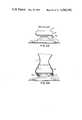
- FIG. 1is a side elevation view of an embodiment of the valve apparatus according to the invention.
- FIG. 2is a cross sectional view of the valve unit of FIG. 1, shown fitted into a balloon and operative to expel air from the balloon.
- FIG. 3is a side elevation view of the valve of the invention.
- FIG. 4is a side elevation view from the opposite side as in FIG. 3.
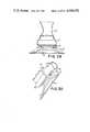
- FIG. 5is a section view taken along lines 5--5 in FIG. 3.
- FIG. 6is a partial section view in accordance with FIG. 5 showing the area of the valve seat in detail.
- FIG. 7is a top plan view of the apparatus of the invention.
- FIG. 8is a section view taken along line A--A in FIG. 1.
- FIG. 9is a bottom plan view of the apparatus of the invention.
- FIG. 10is a bottom plan view of the apparatus having the bottom membrane removed.
- FIG. 11is a section view taken along lines B--B in FIG. 1 showing the attachment of the resilient reed member.
- FIG. 12is a section view taken along lines C--C in FIG. 1.
- FIG. 13is a sectional view of an alternative embodiment of the device, as installed in a balloon.
- FIG. 14is a partial section view of the device of the invention, as attached to a stick.
- FIG. 15is an elevation view of the device according to FIG. 1, installed in a balloon.
- FIG. 16is a section view of a part of the valve casing, showing an intermediate step of manufacture.
- FIG. 17is a section view of an alternative embodiment of the valve body of the invention.
- FIG. 18is an elevation view of the valve according to FIG. 17.
- FIG. 19is a section view taken along lines D--D in FIG. 17.
- FIG. 20is a section view taken along lines E--E in FIG. 18.
- FIG. 21is an elevation view of the valve, the balloon being shown in section.
- FIG. 22is a sectional view illustrating installation of the device of the invention.
- FIG. 23is a perspective view of the device of the invention.
- FIG. 24is a perspective view of the device as installed, and attached to a carrying string.
- FIG. 25is a side elevation view of an alternative embodiment of the invention.
- FIG. 26is a sectional view illustrating installation of the device according to FIG. 22.
- FIG. 27is a detail sectional view of the device according to the embodiment of FIG. 25.
- FIG. 28is a side elevation from the right with respect to FIG. 27.
- FIG. 29is a side elevation showing the completed attachment of balloon and valve of FIG. 25.
- FIG. 30is a side elevation showing an intermediate step in the attachment of FIG. 29.
- the device of the inventionas shown generally in FIG. 1, comprises a casing 30 having an intermediate enlarged portion 32 to be enclosed within the neck of a balloon, and a flaring trumpet portion 36 extending axially from the neck of the balloon.
- a retaining mechanismcomprising hook 40, which interacts with the external contour of the casing enlargement 32, prevents complete ejection of the device in the event of over-inflation or slippage.
- the deviceincludes a retaining cleat 46 for attachment to a string and transversely-threaded flange 48 for attachment to a stick.
- bent over tabs 56prevent access to the internal portions of the device from the balloon side; and, covering membrane 54 prevents access from the user side.
- the devicemay be installed on a deflated balloon, whereupon the user employs the valve of the device as a check valve to pass air or gas such as helium to inflate the balloon, and to hold the air or gas against the resilient pressure of the stretched balloon material.
- the devicecan also be installed in an already-inflated balloon, however, it will be appreciated that steps must be taken to prevent the escape of air or gas during installation.
- the deviceWhen installed on an inflated balloon, the device may be operated to allow controlled release of the air or gas, and emission of a noise.
- FIG. 2also depicts the valve in the open position, that is, while expelling air from balloon 100 through the device of the invention.
- Balloon 100is retained on the device of the invention by neck 104 of balloon 100 enclosing the enlarged portion 32 of casing 30.
- Neck portion 104including the rolled edge 102 of the balloon, exerts sufficient pressure radially inwards to preclude axial movement of the substantially cylindrical casing 30 with respect to balloon 100. Such axial movement would otherwise cause casing 30 to be ejected from neck 104 of balloon 100.
- a generally axial flow of air from balloon 100 through casing 30causes noise due to the vibration of resonant reed 60, placed to partially occlude the air flow path.
- Reed 60is mounted to the casing only at one edge 62, the resonant frequency of reed 60 being determined by the weight, material, and dimensions of the reed and its connection 62.
- the reedis a relatively delicate portion of the device, which can be made inoperative if displaced from its mounting at an area of restricted cross section, and accordingly, tabs 56 are provided to prevent easy access to reed 60.
- Casing 30is preferably formed in two parts, snap fitted together, thereby making it impossible to remove or eject the movable valve body 70.
- the upper reed-enclosing position 34has a downwardly extending flange having an abrupt transition at its edge, over which an upwardly-extending flange of enlargement 32 resiliently locks, the extreme edge of the upward flange engaging the transition of the downward flange.
- Valve body 70is therefore securely locked between reed enclosing section 34 and enlarged section 32 upon assembly.
- Valve body 70is movable between an upward position as shown in FIG. 2, resting against spacers 64, and a downward position in which valve body 70 sealably engages casing 30, to prevent the escape of air from balloon 100. Valve body 70 is depressed into its upward position manually, preferably by pressing the central position of slotted membrane 54.
- the external dimensions of the apparatusare chosen to provide a sufficient enlargement 32 to engage securely the neck of the balloon.
- the portion of largest diameter, namely, the opening of the trumpet 36 of casing 30is chosen to be substantially larger than could be inhaled or swallowed by a child, at least 32 millimeters.
- hook 40 and string cleat 46are made thick enough, that with due regard to the material from which the unit is made (e.g., hard plastic), these protruding portions will not easily break off.
- Threaded flange 48(shown in FIG. 1) is of substantially the same thickness as hood 40 and cleat 46.
- valve body 70Before installation or during actual inflation, as shown in FIG. 5, valve body 70 may rest against spacers 64, the valve being open to air flow. After inflation, the pressure of air within balloon 100, downward against valve body 70, biases the valve into a closed position. It will be appreciated that when the valve body 70 rests against spacers 64, air may pass between the spacers, around the valve body and out of the unit through the trumpet portion.
- Valve body 70is comprised of a circular portion 76 for sealing the valve, and attached downwardly-extending legs 72, angularly spaced to allow air flow when the valve is opened. As shown in cross-section in FIG. 8, the valve body preferably includes three such legs 72, forming a generally-cylindrical but open-to-air flow body.
- valve body 70When the valve of the device is closed, valve body 70 rests against casing 30, sealing the axial opening against passage of gas or air.
- the downwardly-directed flanged edge 78 of valve body 70fits against a complementarily-shaped valve seat 82.
- Valve seat 82is comprised of an annular groove 84, in which viscous, non-drying seal material 86 is disposed. As shown in FIG. 6, groove 84 forms a receptacle for the sealing material 86.
- a portion of sealing material 86is displaced from the annular groove 84, to contact flange 78 and prevent the passage of air. It will be appreciated that viscous sealing material 86 also closes any leaks which would be presented by misalignment or warping in flange 78, or in burrs or other small imperfections in the interacting portions of the valve.
- tabs 56When the device of the invention is removed from the balloon, reed 60 is visible, but protected by tabs 56. Three tabs 56 are shown in FIG. 7. The number allows sufficiently close placement of tabs 56 to prevent any substantial damage to reed 60 due to insertion of fingers, pencils, or other commonly-available objects.
- membrane 54substantially covers the opening formed by trumpet 36.
- a central area 112 of membrane 54is integrally attached to the remainder of the membrane only near the edges of the trumpet, and only at portions of membrane 54 which are deformable upwards by means of peripheral slots 114, adjacent edge 116, which portion is actually attached to trumpet 36.
- Slots 110, which define central depressable portion 112also divide the remaining portions of membrane 54, to allow passage of air.
- Membrane 54may be of any air-permeable material, provided a sufficient resilience is allowed for depression of valve body 70, and also provided that the air flow from a deflating balloon can be accommodated. For example, resilient screen material, or other permeable material, or perforated material having a centrally movable portion would suffice.
- trumpet 36ends in a edge portion 116, to which membrane 54 may be easily attached, for example by glue or heat sealing.
- threaded hole 48provided for attachment to a stick, likewise has a peripheral portion which can be glued directly to membrane 54.
- a ridge 44may be provided in the contour of trumpet 36, for additional strength.
- FIG. 11shows the spacers 64 and reed 60 from below
- FIG. 12shows the reed from above.
- reed 60need only be a movably-attached flap substantially blocking the air passage along the axis of the valve unit.
- reed 60be an integral part of the reed enclosure portion 34 of casing 30, folded over at a relatively-thin connection 62, whereby reed 60 is resiliently-mounted. Passage of air around reed 60 causes the reed to vibrate between a more open position in which air flow presses it downwards, and a more closed position in which air flow becomes restricted, thereby decreasing the pressure and continuing vibration of the reed in its orifice.
- FIG. 13An alternative embodiment of the invention is shown in FIG. 13.
- an extending annular flange 120attached to casing 30 adjacent hook 40, provides further safety against accidental ejection of the balloon valve.
- casing 30In order to be ejected from balloon 100, casing 30 must be displaced axially, allowing balloon 100 to slip axially backwards.
- any such axial movementmust be accompanied by a radial outward movement of the enlarged edge 102 of balloon 100. This movement is exactly what is restricted by hook 40, thereby making the embodiment of FIG. 13 particularly safe against ejection.
- the basic embodiment, shown in FIG. 15,likewise employs hook 40 to prevent complete ejection by holding edge 102 of balloon 100 against movement. Even if the device is partially ejected from balloon 100, hook 40 will retain at least a portion of edge 102, such that the user is not in danger of inhaling or swallowing the device.
- casing 30in particular trumpet 36
- casing 30is provided with a threaded hole 48, for interaction with a balloon-holding stick 50, and also with a cleat 46, to be attached to a string.
- stick 50is preferably attached to threaded hole 48 by means of an additional threaded end 52 for stick 50. End 52 and stick 50 may be attached by gluing.
- reed 60is preferably made as an integral part of the reed enclosing portion 34 of casing 30, and is attached thereto by means of a relatively small connecting portion 62.
- This portionis more easily molded if tabs 56 are bent over after molding, as shown in FIG. 16.
- tabs 56can normally be deformed into protective position by heating and bending them inwards.
- a similar operationcan be employed if desired to displace the body of reed 60 slightly from the orifice in reed enclosure member 34 in which the reed vibrates.
- FIGS. 17-20illustrate an alternative embodiment of valve body 70.
- valve body 124unlike valve body 70, employs a plurality of light weight connection members 126 between the circular valve portion 76 and the portion of valve body 124 which is manually depressable by the user.
- valve body 124operates much the same as valve body 70 in that a flanged edge 78 cooperates with a complementarily shaped valve seat having an annular groove and viscous non-drying material.
- the leg portions 126leave an open area for air flow and can even be used to surround a transversely-disposed pin (not shown), making further captive of valve body 124.
- FIGS. 21 and 22illustrates the partial ejection of the device from balloon 100. Even when air pressure within balloon 100 becomes sufficient to force enlarged portion 32 of casing 30 through the opening defined by the balloon neck, hook 40 nevertheless retains at least a portion of balloon 100, and especially rolled edge 102, which remains confined between hook 40 and enlargement 32.
- the overall deviceas shown in perspective in FIGS. 23 and 24.
- the external dimensionsmust be large enough to preclude inhalation or swallowing.
- the devicecan otherwise be dimensioned in accordance with the expected size of balloons, the only requirement being that the balloon neck be stretched substantially in order to provide sufficient pressure over enlarged portion 32 to prevent ejection of the device.
- hook 40will prevent full ejection, reliable operation requires that such ejection be an infrequent occurrence in any event.
- the flanged portion forming string cleat 46, hook 40 and threaded stick-engaging member 48are all preferably placed along the same diameter to assist in the molding operation.
- Enlarged portion 32preferably snap fits over the reed-enclosing portion 34 of casing 30, very positively connecting the casing parts 32, 34 around valve body 70. In this manner, not only are the reed and valve body safe from damage, but they cannot be broken off or removed and swallowed.
- the device of the inventionis, of course, equally applicable to helium balloons.
- An endless ribbon 130 of stretchable plastic materialforms a loop which may be simply passed over string cleat 46.
- the slightly off-axis placement of cleat 46is such that the larger portion of cleat 46 easily retains the string, against the tendency of the balloon to rise.
- FIGS. 25-30An alternative embodiment of the invention is shown in FIGS. 25-30.
- Hook 134having a thin and resilient end portion, is closely disposed against enlarged portion 32 of casing 30.
- the spacing between hook 134 and casing 32is quite small, and hook 134 must be actually deformed in order to force edge 102 of balloon 110 into the engaged area between hook 134 and casing 30.
- casing 30is preferably provided with an indented area against which hook 134 is closely disposed.
- FIG. 27illustrates the close positioning of hook 134 and casing 30 in detail.
- a downwardly-extending edge 136 of casing 30, together with the outside contour of annular groove 84 of valve seat 82defines a pocket in case 30 in which the end of hook 134 is disposed.
- Hook 134is nevertheless deformable, whereby edge 102 may be forced into cavity 138 defined by hook 134 in casing 30.
- Edge 136 of casing 30is preferably slightly lower than the protruding edge of hook 134, as shown in FIG. 28.
- FIGS. 29 and 30show the engagement of the balloon by the entire casing, and by the hook 134, respectively, in a manner similar to FIGS. 21 and 22.
- the device of the inventionis preferably molded from plastic and is both durable and inexpensive. With the exception of membrane 54, all parts of the device are preferably injection molded in plastic. Membrane 54 may be a transparent or substantially transparent plastic sheet, and is preferably provided with promotional indicia on the inward or outward facing side thereof. For example, advertising materials, cartoon characters or the like may be provided on membrane 54, possibly including some indicia for the depressable portion such as the bulbous nose of a clown or the like.
- the device of the inventionis safe due to the balloon-retention hook, valve body captive design and protective tabs.
- the deviceis also dimensioned such that it cannot be inhaled or swallowed.
- the deviceis nevertheless quite dependable, and also inexpensive.
Landscapes
- Physics & Mathematics (AREA)
- Engineering & Computer Science (AREA)
- Acoustics & Sound (AREA)
- Multimedia (AREA)
- Toys (AREA)
Abstract
Description
Claims (15)
Priority Applications (1)
| Application Number | Priority Date | Filing Date | Title |
|---|---|---|---|
| US06/554,329US4560392A (en) | 1983-11-22 | 1983-11-22 | Noise making balloon valve |
Applications Claiming Priority (1)
| Application Number | Priority Date | Filing Date | Title |
|---|---|---|---|
| US06/554,329US4560392A (en) | 1983-11-22 | 1983-11-22 | Noise making balloon valve |
Publications (1)
| Publication Number | Publication Date |
|---|---|
| US4560392Atrue US4560392A (en) | 1985-12-24 |
Family
ID=24212941
Family Applications (1)
| Application Number | Title | Priority Date | Filing Date |
|---|---|---|---|
| US06/554,329Expired - Fee RelatedUS4560392A (en) | 1983-11-22 | 1983-11-22 | Noise making balloon valve |
Country Status (1)
| Country | Link |
|---|---|
| US (1) | US4560392A (en) |
Cited By (17)
| Publication number | Priority date | Publication date | Assignee | Title |
|---|---|---|---|---|
| US4936809A (en)* | 1989-09-08 | 1990-06-26 | Buddy L Corporation | Sound-producing toy having deformable body |
| DE4130530A1 (en)* | 1991-09-13 | 1993-03-18 | Wiegner Georg Dipl Kaufm | Sealed gas-filled balloon - has gas-tight casing and filler tube closed by valve with annular sealing plate twice valve dia. |
| US6386938B1 (en) | 2001-06-08 | 2002-05-14 | William R. Novak | Sound-producing device |
| US6582274B1 (en) | 2000-04-26 | 2003-06-24 | Basic Fun, Inc. | Noise making toy |
| US20070042671A1 (en)* | 2005-08-16 | 2007-02-22 | Maad Okko | Amusement device |
| US20100100116A1 (en)* | 2008-10-16 | 2010-04-22 | Obalon Therapeutics, Inc. | Intragastric volume-occupying device and method for fabricating same |
| US8292911B2 (en) | 2011-01-21 | 2012-10-23 | Obalon Therapeutics, Inc. | Intragastric device |
| US8647358B2 (en) | 2011-01-21 | 2014-02-11 | Obalon Therapeutics Inc. | Intragastric device |
| US8740927B2 (en) | 2011-01-21 | 2014-06-03 | Obalon Therapeutics Inc. | Intragastric device |
| US8992561B2 (en) | 2011-01-21 | 2015-03-31 | Obalon Therapeutics, Inc. | Intragastric device |
| US9895248B2 (en) | 2014-10-09 | 2018-02-20 | Obalon Therapeutics, Inc. | Ultrasonic systems and methods for locating and/or characterizing intragastric devices |
| US10264995B2 (en) | 2013-12-04 | 2019-04-23 | Obalon Therapeutics, Inc. | Systems and methods for locating and/or characterizing intragastric devices |
| US10335303B2 (en) | 2015-12-07 | 2019-07-02 | Obalon Therapeutics, Inc. | Intragastric device |
| US10350100B2 (en) | 2016-04-12 | 2019-07-16 | Obalon Therapeutics, Inc. | System for detecting an intragastric balloon |
| US10537453B2 (en) | 2015-12-16 | 2020-01-21 | Obalon Therapeutics, Inc. | Intragastric device with expandable portions |
| US11819433B2 (en) | 2016-11-04 | 2023-11-21 | Reshape Lifesciences Inc. | Pressure control system for intragastric device |
| US12440358B2 (en) | 2023-10-10 | 2025-10-14 | Reshape Lifesciences Inc. | Pressure control system for intragastric device |
Citations (19)
| Publication number | Priority date | Publication date | Assignee | Title |
|---|---|---|---|---|
| US584443A (en)* | 1897-06-15 | Edwin wilmont | ||
| US845244A (en)* | 1905-08-02 | 1907-02-26 | Max Lorenz | Valve. |
| US1158206A (en)* | 1915-03-10 | 1915-10-26 | Miller Rubber Co | Toy balloon. |
| US1251758A (en)* | 1917-02-24 | 1918-01-01 | Frederick M Dayton | Toy-balloon valve. |
| US1313705A (en)* | 1919-08-19 | William g | ||
| US1595441A (en)* | 1925-11-18 | 1926-08-10 | Simon F Zenger | Ball |
| US1760022A (en)* | 1928-09-15 | 1930-05-27 | Stowe Herbert Lee | Novelty noise maker |
| US1874915A (en)* | 1930-08-13 | 1932-08-30 | Dill Mfg Co | Air chuck |
| US2263342A (en)* | 1940-10-31 | 1941-11-18 | Westinghouse Air Brake Co | Horn device |
| US2845747A (en)* | 1955-06-10 | 1958-08-05 | Wintriss Inc | Whistle construction for sounding toy |
| US2893165A (en)* | 1955-08-24 | 1959-07-07 | James R Bailey | Morse code balloon signaling device |
| US3095669A (en)* | 1960-01-08 | 1963-07-02 | Marjory Zerin | Sound emitting device |
| DE2063280A1 (en)* | 1969-12-23 | 1971-07-01 | Huebner Vamag | Sealing ring for ball valves etc. |
| DE2107066A1 (en)* | 1970-02-13 | 1971-08-19 | Basevi, John Licmio, Devonport, Auckland (Neuseeland) | Valve for a toy balloon |
| US3670690A (en)* | 1970-11-09 | 1972-06-20 | Robert E Swanson | Aerosol operated horn |
| US3768501A (en)* | 1971-05-10 | 1973-10-30 | Automatic Helium Balloon Syst | Inflatable article valve |
| US4015622A (en)* | 1974-11-22 | 1977-04-05 | National Distillers And Chemical Corporation | Valve for use with inflatable articles such as pneumatic boats |
| US4094347A (en)* | 1976-07-10 | 1978-06-13 | Kikuji Ikemoto | Balloon neck fitting |
| US4194461A (en)* | 1978-04-19 | 1980-03-25 | Custom Concepts, Incorporated | Door alarm toy |
- 1983
- 1983-11-22USUS06/554,329patent/US4560392A/ennot_activeExpired - Fee Related
Patent Citations (19)
| Publication number | Priority date | Publication date | Assignee | Title |
|---|---|---|---|---|
| US584443A (en)* | 1897-06-15 | Edwin wilmont | ||
| US1313705A (en)* | 1919-08-19 | William g | ||
| US845244A (en)* | 1905-08-02 | 1907-02-26 | Max Lorenz | Valve. |
| US1158206A (en)* | 1915-03-10 | 1915-10-26 | Miller Rubber Co | Toy balloon. |
| US1251758A (en)* | 1917-02-24 | 1918-01-01 | Frederick M Dayton | Toy-balloon valve. |
| US1595441A (en)* | 1925-11-18 | 1926-08-10 | Simon F Zenger | Ball |
| US1760022A (en)* | 1928-09-15 | 1930-05-27 | Stowe Herbert Lee | Novelty noise maker |
| US1874915A (en)* | 1930-08-13 | 1932-08-30 | Dill Mfg Co | Air chuck |
| US2263342A (en)* | 1940-10-31 | 1941-11-18 | Westinghouse Air Brake Co | Horn device |
| US2845747A (en)* | 1955-06-10 | 1958-08-05 | Wintriss Inc | Whistle construction for sounding toy |
| US2893165A (en)* | 1955-08-24 | 1959-07-07 | James R Bailey | Morse code balloon signaling device |
| US3095669A (en)* | 1960-01-08 | 1963-07-02 | Marjory Zerin | Sound emitting device |
| DE2063280A1 (en)* | 1969-12-23 | 1971-07-01 | Huebner Vamag | Sealing ring for ball valves etc. |
| DE2107066A1 (en)* | 1970-02-13 | 1971-08-19 | Basevi, John Licmio, Devonport, Auckland (Neuseeland) | Valve for a toy balloon |
| US3670690A (en)* | 1970-11-09 | 1972-06-20 | Robert E Swanson | Aerosol operated horn |
| US3768501A (en)* | 1971-05-10 | 1973-10-30 | Automatic Helium Balloon Syst | Inflatable article valve |
| US4015622A (en)* | 1974-11-22 | 1977-04-05 | National Distillers And Chemical Corporation | Valve for use with inflatable articles such as pneumatic boats |
| US4094347A (en)* | 1976-07-10 | 1978-06-13 | Kikuji Ikemoto | Balloon neck fitting |
| US4194461A (en)* | 1978-04-19 | 1980-03-25 | Custom Concepts, Incorporated | Door alarm toy |
Cited By (43)
| Publication number | Priority date | Publication date | Assignee | Title |
|---|---|---|---|---|
| US4936809A (en)* | 1989-09-08 | 1990-06-26 | Buddy L Corporation | Sound-producing toy having deformable body |
| DE4130530A1 (en)* | 1991-09-13 | 1993-03-18 | Wiegner Georg Dipl Kaufm | Sealed gas-filled balloon - has gas-tight casing and filler tube closed by valve with annular sealing plate twice valve dia. |
| US6582274B1 (en) | 2000-04-26 | 2003-06-24 | Basic Fun, Inc. | Noise making toy |
| US6386938B1 (en) | 2001-06-08 | 2002-05-14 | William R. Novak | Sound-producing device |
| US20070042671A1 (en)* | 2005-08-16 | 2007-02-22 | Maad Okko | Amusement device |
| US12102547B2 (en) | 2008-10-16 | 2024-10-01 | Reshape Lifesciences Inc. | Intragastric volume-occupying device and method for fabricating same |
| US11219543B2 (en) | 2008-10-16 | 2022-01-11 | Reshape Lifesciences Inc. | Intragastric device |
| US20100137897A1 (en)* | 2008-10-16 | 2010-06-03 | Obalon Therapeutics, Inc. | Intragastric device |
| US7854745B2 (en)* | 2008-10-16 | 2010-12-21 | Obalon Therapeutics, Inc. | Intragastric device |
| US8162969B2 (en) | 2008-10-16 | 2012-04-24 | Obalon Therapeutics, Inc. | Intragastric device |
| US20100100116A1 (en)* | 2008-10-16 | 2010-04-22 | Obalon Therapeutics, Inc. | Intragastric volume-occupying device and method for fabricating same |
| US12090075B2 (en) | 2008-10-16 | 2024-09-17 | Reshape Lifesciences Inc. | Intragastric device |
| US20100100117A1 (en)* | 2008-10-16 | 2010-04-22 | Obalon Therapeutics, Inc. | Intragastric device |
| US8845674B2 (en) | 2008-10-16 | 2014-09-30 | Obalon Therapeutics, Inc. | Intragastric device |
| US10874537B2 (en) | 2008-10-16 | 2020-12-29 | Obalon Therapeutics, Inc. | Intragastric volume-occupying device and method for fabricating same |
| US10675165B2 (en) | 2008-10-16 | 2020-06-09 | Obalon Therapeutics, Inc. | Intragastric volume-occupying device and method for fabricating same |
| US9072583B2 (en) | 2008-10-16 | 2015-07-07 | Obalon Therapeutics, Inc. | Intragastric volume-occupying device and method for fabricating same |
| US10327936B2 (en) | 2008-10-16 | 2019-06-25 | Obalon Therapeutics, Inc. | Intragastric device |
| US10085865B2 (en) | 2008-10-16 | 2018-10-02 | Obalon Therapeutics, Inc. | Intragastric volume-occupying device and method for fabricating same |
| US9539132B2 (en) | 2008-10-16 | 2017-01-10 | Obalon Therapeutics, Inc. | Intragastric device |
| US9662239B2 (en) | 2011-01-21 | 2017-05-30 | Obalon Therapeutics, Inc. | Intragastric device |
| US11779482B2 (en) | 2011-01-21 | 2023-10-10 | Reshape Lifesciences Inc. | Intragastric device |
| US12350179B2 (en) | 2011-01-21 | 2025-07-08 | Reshape Lifesciences Inc. | Intragastric device |
| US9468550B2 (en) | 2011-01-21 | 2016-10-18 | Obalon Therapeutics, Inc. | Intragastric device |
| US8292911B2 (en) | 2011-01-21 | 2012-10-23 | Obalon Therapeutics, Inc. | Intragastric device |
| US9351862B2 (en) | 2011-01-21 | 2016-05-31 | Obalon Therapeutics, Inc. | Intragastric device |
| US8647358B2 (en) | 2011-01-21 | 2014-02-11 | Obalon Therapeutics Inc. | Intragastric device |
| US11974934B2 (en) | 2011-01-21 | 2024-05-07 | Reshape Lifesciences Inc. | Intragastric device |
| US10463520B2 (en) | 2011-01-21 | 2019-11-05 | Obalon Therapeutics, Inc. | Intragastric device |
| US9827128B2 (en) | 2011-01-21 | 2017-11-28 | Obalon Therapeutics, Inc. | Intragastric device |
| US10610396B2 (en) | 2011-01-21 | 2020-04-07 | Obalon Therapeutics, Inc. | Intragastric device |
| US9011477B2 (en) | 2011-01-21 | 2015-04-21 | Obalon Therapeutics, Inc. | Intragastric device |
| US10773061B2 (en) | 2011-01-21 | 2020-09-15 | Obalon Therapeutics, Inc. | Intragastric device |
| US8992561B2 (en) | 2011-01-21 | 2015-03-31 | Obalon Therapeutics, Inc. | Intragastric device |
| US8740927B2 (en) | 2011-01-21 | 2014-06-03 | Obalon Therapeutics Inc. | Intragastric device |
| US11737899B2 (en) | 2011-01-21 | 2023-08-29 | Reshape Lifesciences Inc. | Intragastric device |
| US10264995B2 (en) | 2013-12-04 | 2019-04-23 | Obalon Therapeutics, Inc. | Systems and methods for locating and/or characterizing intragastric devices |
| US9895248B2 (en) | 2014-10-09 | 2018-02-20 | Obalon Therapeutics, Inc. | Ultrasonic systems and methods for locating and/or characterizing intragastric devices |
| US10335303B2 (en) | 2015-12-07 | 2019-07-02 | Obalon Therapeutics, Inc. | Intragastric device |
| US10537453B2 (en) | 2015-12-16 | 2020-01-21 | Obalon Therapeutics, Inc. | Intragastric device with expandable portions |
| US10350100B2 (en) | 2016-04-12 | 2019-07-16 | Obalon Therapeutics, Inc. | System for detecting an intragastric balloon |
| US11819433B2 (en) | 2016-11-04 | 2023-11-21 | Reshape Lifesciences Inc. | Pressure control system for intragastric device |
| US12440358B2 (en) | 2023-10-10 | 2025-10-14 | Reshape Lifesciences Inc. | Pressure control system for intragastric device |
Similar Documents
| Publication | Publication Date | Title |
|---|---|---|
| US4560392A (en) | Noise making balloon valve | |
| US4259805A (en) | Amusement device comprising inflatable doll and separable doll enclosure | |
| US4135325A (en) | Inflatable flying saucer toy | |
| US4149338A (en) | Child's toy and game | |
| US2860639A (en) | Pacifier and shield therefor | |
| US5738095A (en) | Tracheostoma device | |
| US2635387A (en) | Toy balloon novelty | |
| US3523563A (en) | Integrally formed self-sealing valve having additionally integral means to render valve airtight | |
| US3048860A (en) | Life preserver | |
| CN220416339U (en) | inflatable objects | |
| US20120289120A1 (en) | Valve and retainer assembly for latex balloons | |
| WO1984001306A1 (en) | Noise making balloon valve | |
| EP0170181A2 (en) | Valvular device for the inflation of balloons, particularly balloons supported by tubular shafts | |
| USRE29050E (en) | Toy with sound producing means | |
| US5020467A (en) | Balloon signalling system | |
| US5469842A (en) | CPR face mask | |
| US2592347A (en) | Inflatable toy | |
| US4828176A (en) | Scented balloon & valve | |
| US2156482A (en) | Confection and novelty toy | |
| CA1223733A (en) | Noise making balloon valve | |
| US3061148A (en) | Inflatable bag | |
| US4248235A (en) | Valve assemblies | |
| US4194461A (en) | Door alarm toy | |
| US4104741A (en) | Novelty hat device | |
| US3204369A (en) | Device for making noise by the puncturing of inflated balloons |
Legal Events
| Date | Code | Title | Description |
|---|---|---|---|
| AS | Assignment | Owner name:VALVE GROUP, LTD. Free format text:CERTIFIED COPY OF ORDER FILED IN THE CIRCUIT COURT, PALM BEACH COUNTY, FLA., ON APRIL 28, 1986 GIVING JUDGMENT IN SAID PATENT TO ASSIGNEE;ASSIGNORS:HAZOURI, FRED A.;SELLARS, ROBERT L.;NICHOLS, BRETT, ARBITRATORS INVOLVING LICINIO, BASEVI;REEL/FRAME:004583/0145 Effective date:19860218 | |
| AS | Assignment | Owner name:VALVE GROUP, LTD., DEFENDANT Free format text:SHERIFF'S BILL OF SALE FILED IN THE 5TH JUDICIAL COURT PALM BEACH COUNTY FLA., ORDERING THE TRANSFER OF SAID PATENT TO ASSIGNEE EFFECTIVE OCT 6, 1987;ASSIGNOR:WILLE, RICHARD P., SHERIFF, INVALVING LICINIO BASEVI, PLAINTIFF;REEL/FRAME:004961/0302 Effective date:19871006 Owner name:VALVE GROUP, LTD., A FLORIDA LIMITED PARTNERSHIP Free format text:ASSIGNMENT OF ASSIGNORS INTEREST.;ASSIGNOR:CLEARY, DANIEL A.;REEL/FRAME:004961/0306 Effective date:19871111 | |
| FEPP | Fee payment procedure | Free format text:PAYMENT IS IN EXCESS OF AMOUNT REQUIRED. REFUND SCHEDULED (ORIGINAL EVENT CODE: F169); ENTITY STATUS OF PATENT OWNER: SMALL ENTITY | |
| REFU | Refund | Free format text:REFUND - PAYMENT OF MAINTENANCE FEE, 4TH YR, SMALL ENTITY, PL 97-247 (ORIGINAL EVENT CODE: R273); ENTITY STATUS OF PATENT OWNER: SMALL ENTITY | |
| REMI | Maintenance fee reminder mailed | ||
| LAPS | Lapse for failure to pay maintenance fees | ||
| FP | Lapsed due to failure to pay maintenance fee | Effective date:19931226 | |
| STCH | Information on status: patent discontinuation | Free format text:PATENT EXPIRED DUE TO NONPAYMENT OF MAINTENANCE FEES UNDER 37 CFR 1.362 |