US4560069A - Package for hazardous materials - Google Patents
Package for hazardous materialsDownload PDFInfo
- Publication number
- US4560069A US4560069AUS06/729,810US72981085AUS4560069AUS 4560069 AUS4560069 AUS 4560069AUS 72981085 AUS72981085 AUS 72981085AUS 4560069 AUS4560069 AUS 4560069A
- Authority
- US
- United States
- Prior art keywords
- bottle
- fiberboard
- insert element
- package assembly
- foam
- Prior art date
- Legal status (The legal status is an assumption and is not a legal conclusion. Google has not performed a legal analysis and makes no representation as to the accuracy of the status listed.)
- Expired - Fee Related
Links
- 239000000383hazardous chemicalSubstances0.000titleclaimsabstractdescription5
- 125000006850spacer groupChemical group0.000claimsabstractdescription40
- 229910052751metalInorganic materials0.000claimsabstractdescription29
- 239000002184metalSubstances0.000claimsabstractdescription29
- 239000011094fiberboardSubstances0.000claimsabstractdescription23
- 230000002745absorbentEffects0.000claimsabstractdescription10
- 239000002250absorbentSubstances0.000claimsabstractdescription10
- 239000011096corrugated fiberboardSubstances0.000claimsabstractdescription9
- 239000011521glassSubstances0.000claimsdescription14
- 239000000463materialSubstances0.000claimsdescription9
- 230000001413cellular effectEffects0.000claimsdescription5
- KXGFMDJXCMQABM-UHFFFAOYSA-N2-methoxy-6-methylphenolChemical compound[CH]OC1=CC=CC([CH])=C1OKXGFMDJXCMQABM-UHFFFAOYSA-N0.000claimsdescription4
- 229920001568phenolic resinPolymers0.000claimsdescription3
- 230000015572biosynthetic processEffects0.000claimsdescription2
- 230000000994depressogenic effectEffects0.000claimsdescription2
- 229920001684low density polyethylenePolymers0.000claimsdescription2
- 239000004702low-density polyethyleneSubstances0.000claimsdescription2
- 239000006261foam materialSubstances0.000claims7
- 230000000284resting effectEffects0.000claims2
- 239000012260resinous materialSubstances0.000claims1
- 239000006260foamSubstances0.000abstractdescription99
- 239000013056hazardous productSubstances0.000abstractdescription9
- 229920005989resinPolymers0.000abstractdescription8
- 239000011347resinSubstances0.000abstractdescription8
- 238000005299abrasionMethods0.000abstractdescription2
- 229920003002synthetic resinPolymers0.000abstractdescription2
- 239000000057synthetic resinSubstances0.000abstractdescription2
- 239000000203mixtureSubstances0.000description9
- 239000007788liquidSubstances0.000description8
- POIUWJQBRNEFGX-XAMSXPGMSA-NcathelicidinChemical compoundC([C@@H](C(=O)N[C@@H](CCCNC(N)=N)C(=O)N[C@@H](CCCCN)C(=O)N[C@@H](CO)C(=O)N[C@@H](CCCCN)C(=O)N[C@@H](CCC(O)=O)C(=O)N[C@@H](CCCCN)C(=O)N[C@@H]([C@@H](C)CC)C(=O)NCC(=O)N[C@@H](CCCCN)C(=O)N[C@@H](CCC(O)=O)C(=O)N[C@@H](CC=1C=CC=CC=1)C(=O)N[C@@H](CCCCN)C(=O)N[C@@H](CCCNC(N)=N)C(=O)N[C@@H]([C@@H](C)CC)C(=O)N[C@@H](C(C)C)C(=O)N[C@@H](CCC(N)=O)C(=O)N[C@@H](CCCNC(N)=N)C(=O)N[C@@H]([C@@H](C)CC)C(=O)N[C@@H](CCCCN)C(=O)N[C@@H](CC(O)=O)C(=O)N[C@@H](CC=1C=CC=CC=1)C(=O)N[C@@H](CC(C)C)C(=O)N[C@@H](CCCNC(N)=N)C(=O)N[C@@H](CC(N)=O)C(=O)N[C@@H](CC(C)C)C(=O)N[C@@H](C(C)C)C(=O)N1[C@@H](CCC1)C(=O)N[C@@H](CCCNC(N)=N)C(=O)N[C@@H]([C@@H](C)O)C(=O)N[C@@H](CCC(O)=O)C(=O)N[C@@H](CO)C(O)=O)NC(=O)[C@H](CC=1C=CC=CC=1)NC(=O)[C@H](CC(O)=O)NC(=O)CNC(=O)[C@H](CC(C)C)NC(=O)[C@@H](N)CC(C)C)C1=CC=CC=C1POIUWJQBRNEFGX-XAMSXPGMSA-N0.000description7
- 238000003780insertionMethods0.000description4
- 230000037431insertionEffects0.000description4
- 230000035939shockEffects0.000description4
- 238000010521absorption reactionMethods0.000description3
- 210000004027cellAnatomy0.000description3
- 230000006378damageEffects0.000description3
- 239000008187granular materialSubstances0.000description3
- 238000005469granulationMethods0.000description3
- 230000003179granulationEffects0.000description3
- 231100001261hazardousToxicity0.000description3
- 238000007373indentationMethods0.000description3
- 238000004806packaging method and processMethods0.000description3
- 239000004033plasticSubstances0.000description3
- 229920003023plasticPolymers0.000description3
- 239000000843powderSubstances0.000description3
- 239000004604Blowing AgentSubstances0.000description2
- OFBQJSOFQDEBGM-UHFFFAOYSA-NPentaneChemical compoundCCCCCOFBQJSOFQDEBGM-UHFFFAOYSA-N0.000description2
- 208000027418Wounds and injuryDiseases0.000description2
- 239000003945anionic surfactantSubstances0.000description2
- 239000011449brickSubstances0.000description2
- 230000000694effectsEffects0.000description2
- 230000002209hydrophobic effectEffects0.000description2
- 230000001939inductive effectEffects0.000description2
- 239000004615ingredientSubstances0.000description2
- 208000014674injuryDiseases0.000description2
- 238000000034methodMethods0.000description2
- 238000002156mixingMethods0.000description2
- 239000002736nonionic surfactantSubstances0.000description2
- 230000035515penetrationEffects0.000description2
- 239000002984plastic foamSubstances0.000description2
- -1polyoxyethylenePolymers0.000description2
- 238000002360preparation methodMethods0.000description2
- 239000007787solidSubstances0.000description2
- 239000004094surface-active agentSubstances0.000description2
- WHOZNOZYMBRCBL-OUKQBFOZSA-N(2E)-2-TetradecenalChemical compoundCCCCCCCCCCC\C=C\C=OWHOZNOZYMBRCBL-OUKQBFOZSA-N0.000description1
- 244000118350Andrographis paniculataSpecies0.000description1
- WKBOTKDWSSQWDR-UHFFFAOYSA-NBromine atomChemical compound[Br]WKBOTKDWSSQWDR-UHFFFAOYSA-N0.000description1
- FBPFZTCFMRRESA-FSIIMWSLSA-ND-GlucitolNatural productsOC[C@H](O)[C@H](O)[C@@H](O)[C@H](O)COFBPFZTCFMRRESA-FSIIMWSLSA-N0.000description1
- 244000261422Lysimachia clethroidesSpecies0.000description1
- 229920003171Poly (ethylene oxide)Polymers0.000description1
- 229920001214Polysorbate 60Polymers0.000description1
- 239000004809TeflonSubstances0.000description1
- 229920006362Teflon®Polymers0.000description1
- 239000002253acidSubstances0.000description1
- 239000003377acid catalystSubstances0.000description1
- 238000004026adhesive bondingMethods0.000description1
- 230000000712assemblyEffects0.000description1
- 238000000429assemblyMethods0.000description1
- 238000010923batch productionMethods0.000description1
- GDTBXPJZTBHREO-UHFFFAOYSA-NbromineSubstancesBrBrGDTBXPJZTBHREO-UHFFFAOYSA-N0.000description1
- 229910052794bromiumInorganic materials0.000description1
- 239000003054catalystSubstances0.000description1
- 210000002421cell wallAnatomy0.000description1
- 210000003850cellular structureAnatomy0.000description1
- 239000011248coating agentSubstances0.000description1
- 238000000576coating methodMethods0.000description1
- 238000009833condensationMethods0.000description1
- 230000005494condensationEffects0.000description1
- 238000010924continuous productionMethods0.000description1
- 238000005260corrosionMethods0.000description1
- 230000007797corrosionEffects0.000description1
- 238000005336crackingMethods0.000description1
- 235000014113dietary fatty acidsNutrition0.000description1
- 230000003292diminished effectEffects0.000description1
- SMVRDGHCVNAOIN-UHFFFAOYSA-Ldisodium;1-dodecoxydodecane;sulfateChemical compound[Na+].[Na+].[O-]S([O-])(=O)=O.CCCCCCCCCCCCOCCCCCCCCCCCCSMVRDGHCVNAOIN-UHFFFAOYSA-L0.000description1
- 238000005315distribution functionMethods0.000description1
- 230000003628erosive effectEffects0.000description1
- 150000002148estersChemical class0.000description1
- 229930195729fatty acidNatural products0.000description1
- 239000000194fatty acidSubstances0.000description1
- 150000004665fatty acidsChemical class0.000description1
- SLGWESQGEUXWJQ-UHFFFAOYSA-Nformaldehyde;phenolChemical compoundO=C.OC1=CC=CC=C1SLGWESQGEUXWJQ-UHFFFAOYSA-N0.000description1
- 238000009472formulationMethods0.000description1
- ISWSIDIOOBJBQZ-UHFFFAOYSA-Nphenol groupChemical groupC1(=CC=CC=C1)OISWSIDIOOBJBQZ-UHFFFAOYSA-N0.000description1
- 229940044654phenolsulfonic acidDrugs0.000description1
- 231100000614poisonToxicity0.000description1
- 230000007096poisonous effectEffects0.000description1
- ODGAOXROABLFNM-UHFFFAOYSA-NpolynoxylinChemical compoundO=C.NC(N)=OODGAOXROABLFNM-UHFFFAOYSA-N0.000description1
- 229920003987resolePolymers0.000description1
- 230000029058respiratory gaseous exchangeEffects0.000description1
- 239000000600sorbitolSubstances0.000description1
- 229920001187thermosetting polymerPolymers0.000description1
- 239000004639urea-formaldehyde foamSubstances0.000description1
Images


Classifications
- B—PERFORMING OPERATIONS; TRANSPORTING
- B65—CONVEYING; PACKING; STORING; HANDLING THIN OR FILAMENTARY MATERIAL
- B65D—CONTAINERS FOR STORAGE OR TRANSPORT OF ARTICLES OR MATERIALS, e.g. BAGS, BARRELS, BOTTLES, BOXES, CANS, CARTONS, CRATES, DRUMS, JARS, TANKS, HOPPERS, FORWARDING CONTAINERS; ACCESSORIES, CLOSURES, OR FITTINGS THEREFOR; PACKAGING ELEMENTS; PACKAGES
- B65D5/00—Rigid or semi-rigid containers of polygonal cross-section, e.g. boxes, cartons or trays, formed by folding or erecting one or more blanks made of paper
- B65D5/42—Details of containers or of foldable or erectable container blanks
- B65D5/44—Integral, inserted or attached portions forming internal or external fittings
- B65D5/50—Internal supporting or protecting elements for contents
- B65D5/5028—Elements formed separately from the container body
- B65D5/5088—Plastic elements
- B65D5/509—Foam plastic elements
- B—PERFORMING OPERATIONS; TRANSPORTING
- B65—CONVEYING; PACKING; STORING; HANDLING THIN OR FILAMENTARY MATERIAL
- B65D—CONTAINERS FOR STORAGE OR TRANSPORT OF ARTICLES OR MATERIALS, e.g. BAGS, BARRELS, BOTTLES, BOXES, CANS, CARTONS, CRATES, DRUMS, JARS, TANKS, HOPPERS, FORWARDING CONTAINERS; ACCESSORIES, CLOSURES, OR FITTINGS THEREFOR; PACKAGING ELEMENTS; PACKAGES
- B65D5/00—Rigid or semi-rigid containers of polygonal cross-section, e.g. boxes, cartons or trays, formed by folding or erecting one or more blanks made of paper
- B65D5/42—Details of containers or of foldable or erectable container blanks
- B65D5/44—Integral, inserted or attached portions forming internal or external fittings
- B65D5/50—Internal supporting or protecting elements for contents
- B65D5/5028—Elements formed separately from the container body
- B65D5/5035—Paper elements
- B65D5/5045—Tubular lining and supporting elements
Definitions
- This inventionrelates to novel packaging assemblies for holding, handling and transporting hazardous materials.
- Hazardous materialsinclude corrosive, flammable or poisonous liquids or solids.
- the present inventionemploys as a cushion for a bottle containing a hazardous material and disposed in a metal can a plurality of non-granular synthetic, resinous foam elements each cut or molded into a shape which conforms with the shape of the metal can and the bottle.
- the bottleis typically no more than a quart in size, but can be larger.
- Non-limiting examples of such foamsare disclosed in U.S. Pat. No. 2,753,277 to Smithers, which is hereby incorporated by reference.
- the Smithers patentdiscloses absorbent phenolic condensation resin foam elements such as phenol-formaldehyde foam elements and also urea-formaldehyde foam elements for use in floral arrangements.
- the resins disclosed in the patentare prepared in block or brick form.
- the present inventionis not limited to these foams and other synthetic resin foams capable of both a cushioning and absorbent function can be employed.
- the foams to be employedare cellular in nature and have a high degree of absorptivity.
- a resinis selected to prepare the foam which will not react with the hazardous material contained in the bottle but instead will rapidly absorb and retain the material upon leakage or accidental breakage of the glass.
- the amount of foamcan be established so that the total absorptive capacity of the foam for the contents of the bottle can be two-fold, three-fold, or greater, than the quantity of hazardous material contained in the bottle. Thereby, if there should be spillage the cellular foam will tend to retain substantially the entire quantity of hazardous material and to inhibit and delay corrosive action of spilled liquid on the surrounding metal can. This will retard corrosive penetration of the metal can. It will also retard or avoid leakage of the hazardous material from the metal can in the event some corrosive penetration of the can should occur.
- the synthetic resinous foamserves as a cushion for the bottle to protect the bottle from mechanical shock and thereby help to avoid cracking or breakage thereof.
- This cushioning effectis achieved in accordance with this invention without incurring the messiness of the granular material of the prior art upon unpacking of the metal can and removal of the bottle therefrom.
- the resinous cellular packaging foam elements of this inventionare non-resilient, penetrable and frangible.
- a significant disadvantage of blocks, bricks or cylinders of the foams as used in this inventionis that upon abrasion, the material at the surface of frictional contact will disintegrate into a fine powder because of its thin-walled cellular structure. The powder tends to come off onto the hands on handling and any motion can cause it to be freed from the surface of the resin and be carried into the air, causing annoyance in breathing.
- the bottleis surrounded on all sides by a plurality of presized foam elements.
- At least one of the foam elementsis shaped as a hollow cylinder into which the bottle is longitudinally inserted in a snug fit.
- the hollow cylinder foam elementis of substantially the same height as the bottle.
- a top or upper foam cylindrical disc elementis disposed above the hollow cylinder element.
- a bottom or lower foam cylindrical disc elementis disposed below the hollow cylinder.
- the top and bottom of the bottleis much narrower than the lateral surface so that the impact force upon the foam upon movement of the bottle in a longitudinal direction is concentrated over a much smaller surface area, resulting in a relatively higher impact pressure.
- the frangible foamtends to disintegrate at the top and bottom of the bottle during transit, wearing indentations at the contact surfaces and inducing granulation and powder formation.
- the indentations formedprovide a progressively greater clearance for axial movement of the bottle to progressively increase the force of impact on the foam element with time. Thereby, disintegration of the foam occurs at an accelerating rate.
- top and bottom cylindrical foam disc elementsare provided of a diameter which is much larger than the diameter of the bottle, or at least the top cylindrical disc element is substantially larger than the diameter of the cap of the bottle and the bottom disc is substantially larger than the diameter of the bottom of the bottle.
- spacer elementspreferably shaped as discs, fabricated of a material other than the foam and which are rigid, but soft and less frangible are disposed between the top and bottom cylindrical foam disc elements and the bottle, respectively.
- the spacer discscan be essentially non-frangible under the conditions of use.
- the spacer discscan conveniently comprise a fiberboard insert.
- the bottleWhen the bottle moves relative to the foam elements during transit due to vehicular bouncing it will impinge upon the non-frangible spacer discs rather than upon the frangible foam disc elements.
- the force of impingementwill be transferred through the non-frangible spacer disc to all portions of the frangible foam disc in contact with the spacer disc.
- the spacer discWhen the spacer disc is coextensive with the entire facing surface of the foam disc element the force of impingement is distributed along the entire surface of the foam disc facing the bottle, rather than concentrated at the locale of contact of the bottle with the foam disc.
- the spacer discinduces an effective increase of contact area so that the pressure upon the foam disc due to impingement by the bottle is reduced.
- the non-foam spacer discprovides a load distribution function which reduces wear and granulation of the foam.
- the non-foam spacer discmaintains the bottle in a more stationary condition relative to the foam elements and the metal can than otherwise would be possible.
- the canis also provided with protection from mechanical damage from without.
- This protectionis provided by disposing the metal can within a corrugated fiberboard outer box having a separate corrugated fiberboard insert element.
- the fiberboard insert elementis smaller than the outer box to permit it to fit within the outer box.
- the side walls of the insert elementare parallel to the side walls of the outer box.
- Each sidewall of the fiberboard insert elementis provided with upper and lower outwardly folding edge flaps which serve to brace the insert element within the outer box and to provide a fixed lateral clearance therebetween.
- the insert elementhas an inner space which is preferably square in cross-section and which has a wall width which is about the size of the diameter of the metal can, allowing the can to fit snugly into the inner space of the insert element.
- the walls of the insert elementare provided with upper and lower inwardly flexible corner eaves to brace the top and bottom of the can within the insert element and to provide fixed upper and lower clearance spaces between the metal can and the outer box.
- the inwardly flexible corner eavesare retractable by reversing the inward flexing process to allow insert and removal of the metal can from the insert element.
- This spaceprovides mechanical protection for the can from shock and outside injury, e.g., due to crushing. For example, if the fork of a lift truck were to accidentally penetrate the outer box, the fixed space would provide a buffer zone within which fork movement could be reversed without contact with and injury to the can itself.
- FIG. 1is a longitudinal cross-sectional view of a metal can containing the bottle, the foam elements and the cardboard spacer discs;
- FIG. 2is an exploded view showing the arrangement and the mode of assembly of the various elements in and around the metal can;
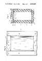
- FIG. 3is a view of the outer cardboard box containing the cardboard insert element
- FIG. 4is an exposed view of the cardboard insert element as it is arranged in FIG. 3;
- FIG. 5is a longitudinal cross-sectional view of the cardboard box and the cardboard insert element with a full view of a metal can mounted within the cardboard insert element.
- FIG. 1shows cylindrical metal can 10 having a sealed bottom 12 and a press-on and removable friction lid 14.
- Glass bottle 16 containing a hazardous materialis disposed in the interior of can 10 and is closed by a plastic screw-on cap 18.
- the outside glass surface of bottle 16is plasticoated to provide protection against leakage in case the glass should crack and to protect the glass against breakage.
- Cap 18can be teflon lined.
- the juncture of neck 20 of bottle 16 and cap 18can be wrapped by friction tape, not shown, to provide additional protection against leakage of the hazardous contents within bottle 16.
- Glass bottle 16is entirely surrounded by a plurality of plastic foam elements.
- the plastic foamis arranged as at least three separate foam elements including bottom foam disc 22, central hollow foam cylinder 24 and top foam disc 26.
- Top and bottom foam discs 22 and 26 and central foam cylinder 24each has about the same outside diameter as the interior diameter of can 10. Bottom and top foam discs 22 and 26 do not require any hollowed out portion.
- central foam disc 24has a cylindrical bore 28 extending longitudinally therethrough having a diameter substantially equal to the outside diameter of bottle 16.
- Bottle 16is inserted into bore 28 in an essentially friction tight relationship therewith so that central annular foam element 24 is coextensive with bottle 16 along essentially the entire height of bottle 16.
- cap 18 of bottle 16has a top flat surface having a relatively small area indicated at 34, while corrugated fiberboard spacer 32 and foam disc 26 each have a larger area as indicated at surfaces 36 and 38, respectively. If corrugated spacer 32 were absent, the surface 34 of cap 18 would obtrude directly against a similar facing area of foam disc 26 and tend to granulate the frangible disc along that area, eroding an indentation at the area of contact.
- metal can 10 and its contentscan be assembled with all elements in friction tight contact so there is essentially no relative movement of the elements within the can.
- the diameter of bore 28 of foam element 24is essentially equal to the outside diameter of bottle 16 while the height of bore 28 is essentially equal to the height of bottle 16 plus assembled cap 18.
- lid 14 of can 10is provided with a depression 40 which is sufficiently deep so that upon assembly of lid 14 to can 10 depression 40 contacts the top of foam disc 26 to force all the elements within the metal can in friction tight engagement and to essentially avoid relative movement of interior elements during vehicle bouncing in transit.
- FIG. 2illustrates the sequence of assembly of the elements in can 10.
- bottom foam disc 22is inserted into can 10 and rests upon the bottom 12 thereof.
- corrugated fiberboard spacer disc 30is inserted and rests upon bottom foam disc 22.
- annular foam cylinder 24is inserted and rests upon corrugated spacer disc 30.
- Glass bottle 16is then inserted snugly into core 28 of annular disc 24 and contacts the core in friction tight engagement therewith.
- top cap surface 34is essentially flush with top core surface 42.
- corrugated spacer disc 32is inserted so that it is essentially in contact with top cap surface 34 and top core surface 42.
- the assemblyis completed by insertion of top foam disc 26 followed by cover lid 14 which is depressed downwardly onto open upper end of can 10 so that depression 40 on lid 14 forces all the elements into vertical friction tight engagement.
- the entire cancan be inserted into bag 44 comprising low density polyethylene for further protection against leakage of hazardous material.
- bag 44comprising low density polyethylene for further protection against leakage of hazardous material.
- the top of bag 44can be gathered in goose neck fashion and tied within itself in conventional manner, not shown.
- the metal can assemblyis ready for insertion into corrugated cardboard insert element 48, which is shown in FIG. 4, which in turn is contained in cardboard box 46, which is shown in FIG. 3.
- the completed assemblyis shown in FIG. 5 and is ready for shipment.
- fiberboard insert element 48comprises four vertical walls 50 which define an interior space 52.
- Each vertical wall 50has a bottom fold 54 and a flap element 56 adapted to be folded outwardly thereon.
- each vertical wall 50has a top fold 58 and a top flap element 60 adapted to be folded outwardly thereon.
- Insert element 48is also provided with an upper pair of flexible eaves 62 on diagonally opposite corners and with a corresponding pair of lower flexible eaves 64 on diagonally opposite corners, of which one is shown.
- Each flexible eaveis formed by making two corner cuts on adjacent walls of spacer element 48, one corner cut occurring at a fold 54 or 58 and the other corner cut occurring a short distance from fold 54 or 58 in the direction of the center of insert element 48. After the two corner cuts are made the eaves are formed by manually pushing inwardly a corner bounded by two cuts to invert the included corner-fold, such as corner fold 66.
- Corner fold 66is generally convex when viewed from the exterior of insert element 48, but after eave 62 is formed corner fold 66 becomes concave when viewed from the exterior, as shown at 66a.
- Flexible corner eaves 62 and 64can be alternately formed and abolished by flexing the associated corner fold inwardly and outwardly, respectively, as desired.
- FIG. 3shows corrugated fiberboard insert element 48 disposed within outer corrugated fiberboard box 46.
- insert element 48occupies essentially the entire interior height of outer box 46.
- Outfolded flaps 56 and 60brace interior element 48 away from the walls of outer box 46 to provide a lateral space 68 therebetween.
- a lower space 70is provided between the bottom 12 of can 10 and the bottom of outer box 46.
- upper eaves 62must be manually abolished by outward flexing to accommodate insertion of can 10 into insert element 48.
- upper eaves 62are manually formed to provide fixed space 72 between lid 14 and the top of box 46.
- top flaps 74 of outer box 46are closed and sealed by gluing or by tape, as indicated in FIG. 5.
- FIG. 5shows that the can 10 is braced laterally and from above and below to hold the can stationary and to provide a clearance space on all sides between can 10 and outer box 46. No matter whether outer box 46 remains upright, is turned on its side or is turned upside down, can 10 will remain rigidly fixed in position within outer box 46. Furthermore, if container 46 is accidently pierced as by the fork of a lift truck, there is provided a safety clearance zone around the entire outer periphery of can 10 to allow time for the operator to realize and reverse the intrusion before can 10 itself is penetrated.
- a suitable synthetic foam for the present inventionwill function as a shock isolator to protect the glass vial and also as an absorbent, in the event of vial breakage to contain the hazardous liquid and prevent any leakage thereof from the can.
- One such foam which meets both of these requirementsis OASIS brand, a registered trademark of Smithers-Oasis Company, for a thermosetting phenol-formaldehyde foam.
- This foamis available in varying densities, on the order of from about 1.1 to about 1.4 lbs/ft 3 and is well suited to absorb a wide variety of both hydrophilic and hydrophobic liquids ranging from aqueous to organic as well as elemental liquids such as bromine.
- Practice of the present inventionneed not be limited to foams within this density range. For example, greater densities, e.g., 10 lbs/ft 3 are suitable.
- the foamis an open-cell variety and is quite easily cut into a desirable configuration such as the open cylinder and discs depicted in the drawings.
- phenol-formaldehyde foamsare generally well known in the industry.
- the ingredientsprimarily comprise an A stage resin or resole, an acid catalyst, a blowing agent and a mixture of nonionic and anionic surfactants selected to emulsify the other components and produce a stable foam of uniform and desired cell structure.
- the surfactantsalso have a role in determining the absorbent nature of the foam, i.e., hydrophilic or hydrophobic. Thus, selective absorbency can be controlled by cell structure and surfactant coating of the cells.
- foamscan be made in either batch or continuous processes. It is usually convenient to produce a larger block of the foam from which the cylindrical containers can be cut with a sharp knife.
- composition Ahas been produced hereinbelow with all parts being on the basis of parts per hundred parts of resin.
- the foamis prepared by mixing all ingredients, without the acid, to provide a uniform blend followed by the addition of said catalyst with a brief mixing, on the order of one minute or less. The mixture is then allowed to foam in a mold and will set up firm to the touch in a manner of minutes. Afterwards it can be handled as a solid. It is to be understood that the foregoing foam composition has been presented solely to provide those skilled in the art with a suitable composition for practice of the subject invention. The present invention is not to be limited to this one formulation or to any method of preparation.
- a foam element as described hereinpossesses remarkable absorbent qualities. For example, it can absorb the maximum quantity of liquid it is capable of holding in from 15 seconds to no more than several minutes. Yet, when removed from the liquid, drainage will normally not exceed two percent. This remarkable absorption and near lack of drainage is due to the openness of the cell wall which favors ingress rather than egress.
- An amount of foamcan be employed in a packaging assembly which has an absorption capacity of two, three or more times the quantity of hazardous liquid contained in the glass vial.
Landscapes
- Engineering & Computer Science (AREA)
- Mechanical Engineering (AREA)
- Buffer Packaging (AREA)
- Packages (AREA)
- Wrappers (AREA)
- Packging For Living Organisms, Food Or Medicinal Products That Are Sensitive To Environmental Conditiond (AREA)
- Packaging Frangible Articles (AREA)
Abstract
Description
______________________________________ Composition A Components Parts ______________________________________ 2670 resin, Union Carbide 100.0 Tween 60.sup.a 2.5 Texapon N25.sup.b 5.0 Phenolsulfonic acid 14.0 Pentane.sup.c 5.0 ______________________________________ .sup.a nonionic surfactant, polyoxyethylene derivative of fatty acid partial esters of sorbitol anhydrides .sup.b anionic surfactant, sodium lauryl ether sulfate .sup.c blowing agent
Claims (18)
Priority Applications (7)
| Application Number | Priority Date | Filing Date | Title |
|---|---|---|---|
| US06/729,810US4560069A (en) | 1985-05-02 | 1985-05-02 | Package for hazardous materials |
| EP86302788AEP0203691A2 (en) | 1985-05-02 | 1986-04-15 | Package for hazardous materials |
| AU56352/86AAU5635286A (en) | 1985-05-02 | 1986-04-18 | Package for hazardous materials |
| CA000507342ACA1287601C (en) | 1985-05-02 | 1986-04-23 | Package for hazardous materials |
| JP61098412AJPS61259985A (en) | 1985-05-02 | 1986-04-30 | Package for dangerous material |
| DK199486ADK199486A (en) | 1985-05-02 | 1986-05-01 | PACKAGING FOR A HAZARDOUS MATERIAL |
| CA000616014ACA1310304C (en) | 1985-05-02 | 1991-03-04 | Package for hazardous materials |
Applications Claiming Priority (1)
| Application Number | Priority Date | Filing Date | Title |
|---|---|---|---|
| US06/729,810US4560069A (en) | 1985-05-02 | 1985-05-02 | Package for hazardous materials |
Publications (1)
| Publication Number | Publication Date |
|---|---|
| US4560069Atrue US4560069A (en) | 1985-12-24 |
Family
ID=24932721
Family Applications (1)
| Application Number | Title | Priority Date | Filing Date |
|---|---|---|---|
| US06/729,810Expired - Fee RelatedUS4560069A (en) | 1985-05-02 | 1985-05-02 | Package for hazardous materials |
Country Status (6)
| Country | Link |
|---|---|
| US (1) | US4560069A (en) |
| EP (1) | EP0203691A2 (en) |
| JP (1) | JPS61259985A (en) |
| AU (1) | AU5635286A (en) |
| CA (1) | CA1287601C (en) |
| DK (1) | DK199486A (en) |
Cited By (48)
| Publication number | Priority date | Publication date | Assignee | Title |
|---|---|---|---|---|
| US4715513A (en)* | 1985-12-09 | 1987-12-29 | Shelton Jr Amos H | Toxic material storage vessel containment system |
| US4747512A (en)* | 1987-06-19 | 1988-05-31 | Lo Kin K | Transportation packaging for liquids |
| US4762227A (en)* | 1987-11-19 | 1988-08-09 | Patterson Robert C | Resilient housing for remote controllers |
| US4803042A (en)* | 1987-11-23 | 1989-02-07 | Westinghouse Electric Corp. | Nuclear reactor core component shipping container |
| DE3832009A1 (en)* | 1987-09-25 | 1989-04-13 | Wissenschaftlich Tech Ingenieu | Multiple part container |
| US4823956A (en)* | 1986-08-13 | 1989-04-25 | Donaldson Company, Inc. | Composite container and its method of manufacture |
| US4838420A (en)* | 1987-09-24 | 1989-06-13 | Bonneville International Corporation | Packaging for point of sale display, shipment and storage of cassette recordings and methods |
| US4877136A (en)* | 1987-04-17 | 1989-10-31 | Bridgestone Corporation | Vibration free container for transportation |
| US4880119A (en)* | 1987-04-06 | 1989-11-14 | Simon B Kenneth | Cushioned container for hazardous material |
| US4884684A (en)* | 1988-05-06 | 1989-12-05 | Minnesota Mining And Manufacturing Company | Containment device for biological materials |
| US4949840A (en)* | 1989-12-11 | 1990-08-21 | Brown J Theodore | Specimen collection kit for mailing |
| US4955480A (en)* | 1989-07-21 | 1990-09-11 | Sexton Wilson C | Portable insulated carrier |
| US4964529A (en)* | 1989-06-30 | 1990-10-23 | Houston Robert S | Gas tank container |
| US4986419A (en)* | 1987-09-24 | 1991-01-22 | Bonneville International Corporation | Packaging for point of sale display, shipment and storage of cassette recordings and methods |
| US5024865A (en)* | 1989-04-07 | 1991-06-18 | Minnesota Mining And Manufacturing Company | Sorbent, impact resistant container |
| US5029699A (en)* | 1990-08-09 | 1991-07-09 | Minnesota Mining And Manufacturing Company | Impact resistant container for hazardous materials |
| US5219504A (en)* | 1989-04-07 | 1993-06-15 | Minnesota Mining And Manufacturing Company | Method of making sorbent, impact resistant container |
| WO1994004434A1 (en)* | 1992-08-11 | 1994-03-03 | Environmental Protection Polymers, Inc. | Cushioned overpack for containing hazardous substances |
| US5378096A (en)* | 1993-12-09 | 1995-01-03 | Shippers Paper Products Company | Collapsible and expandable void filler |
| US5407077A (en)* | 1994-02-10 | 1995-04-18 | Sinclair, Sr; Robert | Cushion packaging for hazardous liquids |
| US5433412A (en)* | 1994-04-18 | 1995-07-18 | Watt; Ramon C. | Medical waste infectious substance disposal and transportation system |
| US5615795A (en)* | 1995-01-03 | 1997-04-01 | Tipps; Steven V. | Hazardous materials container |
| US5641068A (en)* | 1995-06-15 | 1997-06-24 | Hewlett-Packard Company | Adjustable and reusable protective packaging system |
| US5709301A (en)* | 1996-11-01 | 1998-01-20 | Couch; Robert Lincoln | Painting implement keeper |
| US5998800A (en)* | 1998-02-12 | 1999-12-07 | The United States Of America As Represented By The United States Department Of Energy | Pipe overpack container for trasuranic waste storage and shipment |
| US5996799A (en)* | 1998-01-22 | 1999-12-07 | Exakt Technologies, Inc. | Shipping container and method |
| US6166391A (en)* | 1999-05-21 | 2000-12-26 | General Electric Company | Uranium oxide shipping container |
| US20020144926A1 (en)* | 2000-09-08 | 2002-10-10 | Rutledge Arthur G. | Package and method of packaging dangerous goods for transport |
| US6595383B2 (en) | 2000-02-22 | 2003-07-22 | Scott Technologies, Inc. | Packaging for shipping compressed gas cylinders |
| US6666333B2 (en)* | 2001-02-09 | 2003-12-23 | Meadwestvaco Packaging Systems, Llc | Carton and carton blank |
| US20030234255A1 (en)* | 2002-03-25 | 2003-12-25 | Tuscarora Incorporated | Insulated shipping container |
| US20050077201A1 (en)* | 2003-10-09 | 2005-04-14 | Benq Corporation | Packaging assembly and removal method thereof |
| US7093412B1 (en)* | 1999-02-24 | 2006-08-22 | Shin-Etsu Chemical Co., Ltd. | Glass base material packing method |
| US20060214120A1 (en)* | 2004-11-10 | 2006-09-28 | Huang Roger C | Apparatus for shipping radioactive material |
| US7137528B1 (en)* | 2003-05-16 | 2006-11-21 | Cry Twenty-Two, Inc. | Automated Meds dispenser system |
| US7186994B1 (en)* | 2003-09-17 | 2007-03-06 | The S.M. Stoller Corporation | Container for transport of hazardous materials |
| US20070235364A1 (en)* | 2006-04-07 | 2007-10-11 | Rueschhoff Kenneth J | Cartons for pistons and method of packing pistions in cartons |
| US20110187028A1 (en)* | 2007-12-07 | 2011-08-04 | Joseph Menning | Blow Molded Liner for Overpack Container and Method of Manufacturing the Same |
| US20120055824A1 (en)* | 2010-09-07 | 2012-03-08 | Michael Nash | Data transmission blocking holder for personal data transmitting and receiving devices |
| WO2013096579A1 (en)* | 2011-12-21 | 2013-06-27 | Advanced Technology Materials, Inc. | Liner-based shipping and dispensing systems |
| US20140251867A1 (en)* | 2011-08-25 | 2014-09-11 | Aldo Francisco Castaneda | Reusable Protective Enclosure System For An Open-Ended Tubular Member |
| US20150179289A1 (en)* | 2013-10-30 | 2015-06-25 | NorthStar Medical Radionuclides LLC | Parent radionuclide container |
| US9211993B2 (en) | 2011-03-01 | 2015-12-15 | Advanced Technology Materials, Inc. | Nested blow molded liner and overpack and methods of making same |
| US9522773B2 (en) | 2009-07-09 | 2016-12-20 | Entegris, Inc. | Substantially rigid collapsible liner and flexible gusseted or non-gusseted liners and methods of manufacturing the same and methods for limiting choke-off in liners |
| EP3062313B1 (en) | 2015-02-26 | 2017-02-01 | GNS Gesellschaft für Nuklear-Service mbH | Container for storing radioactive inventory and method for producing the container |
| US9637300B2 (en) | 2010-11-23 | 2017-05-02 | Entegris, Inc. | Liner-based dispenser |
| US10633163B1 (en)* | 2018-01-24 | 2020-04-28 | William M. Arnold | Transport container for radioactive material |
| US20220242644A1 (en)* | 2021-02-02 | 2022-08-04 | American Labelmark Company | Container for Shipping Hazardous Materials |
Families Citing this family (5)
| Publication number | Priority date | Publication date | Assignee | Title |
|---|---|---|---|---|
| JPH0353481U (en)* | 1989-09-29 | 1991-05-23 | ||
| JPH062509B2 (en)* | 1989-12-06 | 1994-01-12 | 株式会社エスアールエル | Safe remote transportation method and transportation equipment for specimens |
| FR2674224B1 (en)* | 1991-03-22 | 1993-07-16 | Sud Ouest Isolants Modernes | IMPROVED ANTI-SHOCK PACKAGE FOR FRAGILE OBJECTS SUCH AS BOTTLES AND PROCESS FOR OBTAINING SAME. |
| JPH0535635U (en)* | 1991-10-11 | 1993-05-14 | ニツセー株式会社 | Beverage container |
| CA2145528A1 (en)* | 1992-09-29 | 1994-04-14 | John Adrian Donkers | Containers for potentially hazardous substances |
Citations (13)
| Publication number | Priority date | Publication date | Assignee | Title |
|---|---|---|---|---|
| US1985075A (en)* | 1930-12-02 | 1934-12-18 | Gen Electric | Packing container for various articles |
| US2485737A (en)* | 1946-06-28 | 1949-10-25 | Jr George W Jacoby | Fingerprint machine |
| US2753277A (en)* | 1953-11-03 | 1956-07-03 | Vernon L Smithers | Absorbent material for floral arrangements |
| US3111223A (en)* | 1962-07-30 | 1963-11-19 | Union Bag Camp Paper Corp | Unitized shelf loading carton |
| US3256441A (en)* | 1962-11-26 | 1966-06-14 | Abbott Lab | Container system for radioactive material |
| US3432666A (en)* | 1964-03-13 | 1969-03-11 | Atomic Energy Authority Uk | Containers for transporting radioactive and/or fissile materials |
| US3500996A (en)* | 1968-10-28 | 1970-03-17 | Us Air Force | Shipping container |
| US3531644A (en)* | 1967-01-31 | 1970-09-29 | Mallinckrodt Chemical Works | Packaging assembly for radioactive materials |
| US3882315A (en)* | 1973-04-12 | 1975-05-06 | Mallinckrodt Chemical Works | Shipping container for a bottle of radioactive material |
| US3999653A (en)* | 1975-03-11 | 1976-12-28 | The Dow Chemical Company | Packaging for hazardous liquids |
| US4020355A (en)* | 1973-02-16 | 1977-04-26 | E. R. Squibb & Sons, Inc. | Receptacle for radioactive material |
| US4081688A (en)* | 1976-07-22 | 1978-03-28 | Chevron Research Company | Shielded container |
| US4190160A (en)* | 1979-03-06 | 1980-02-26 | The United States Of America As Represented By The United States Department Of Energy | Accident resistant transport container |
- 1985
- 1985-05-02USUS06/729,810patent/US4560069A/ennot_activeExpired - Fee Related
- 1986
- 1986-04-15EPEP86302788Apatent/EP0203691A2/ennot_activeWithdrawn
- 1986-04-18AUAU56352/86Apatent/AU5635286A/ennot_activeAbandoned
- 1986-04-23CACA000507342Apatent/CA1287601C/ennot_activeExpired - Lifetime
- 1986-04-30JPJP61098412Apatent/JPS61259985A/enactivePending
- 1986-05-01DKDK199486Apatent/DK199486A/ennot_activeApplication Discontinuation
Patent Citations (13)
| Publication number | Priority date | Publication date | Assignee | Title |
|---|---|---|---|---|
| US1985075A (en)* | 1930-12-02 | 1934-12-18 | Gen Electric | Packing container for various articles |
| US2485737A (en)* | 1946-06-28 | 1949-10-25 | Jr George W Jacoby | Fingerprint machine |
| US2753277A (en)* | 1953-11-03 | 1956-07-03 | Vernon L Smithers | Absorbent material for floral arrangements |
| US3111223A (en)* | 1962-07-30 | 1963-11-19 | Union Bag Camp Paper Corp | Unitized shelf loading carton |
| US3256441A (en)* | 1962-11-26 | 1966-06-14 | Abbott Lab | Container system for radioactive material |
| US3432666A (en)* | 1964-03-13 | 1969-03-11 | Atomic Energy Authority Uk | Containers for transporting radioactive and/or fissile materials |
| US3531644A (en)* | 1967-01-31 | 1970-09-29 | Mallinckrodt Chemical Works | Packaging assembly for radioactive materials |
| US3500996A (en)* | 1968-10-28 | 1970-03-17 | Us Air Force | Shipping container |
| US4020355A (en)* | 1973-02-16 | 1977-04-26 | E. R. Squibb & Sons, Inc. | Receptacle for radioactive material |
| US3882315A (en)* | 1973-04-12 | 1975-05-06 | Mallinckrodt Chemical Works | Shipping container for a bottle of radioactive material |
| US3999653A (en)* | 1975-03-11 | 1976-12-28 | The Dow Chemical Company | Packaging for hazardous liquids |
| US4081688A (en)* | 1976-07-22 | 1978-03-28 | Chevron Research Company | Shielded container |
| US4190160A (en)* | 1979-03-06 | 1980-02-26 | The United States Of America As Represented By The United States Department Of Energy | Accident resistant transport container |
Cited By (60)
| Publication number | Priority date | Publication date | Assignee | Title |
|---|---|---|---|---|
| US4715513A (en)* | 1985-12-09 | 1987-12-29 | Shelton Jr Amos H | Toxic material storage vessel containment system |
| US4823956A (en)* | 1986-08-13 | 1989-04-25 | Donaldson Company, Inc. | Composite container and its method of manufacture |
| US4880119A (en)* | 1987-04-06 | 1989-11-14 | Simon B Kenneth | Cushioned container for hazardous material |
| US4877136A (en)* | 1987-04-17 | 1989-10-31 | Bridgestone Corporation | Vibration free container for transportation |
| US5356009A (en)* | 1987-06-08 | 1994-10-18 | Environmental Protection Polymers, Inc. | Cushioned overpack for containing hazardous substances |
| US4747512A (en)* | 1987-06-19 | 1988-05-31 | Lo Kin K | Transportation packaging for liquids |
| US4986419A (en)* | 1987-09-24 | 1991-01-22 | Bonneville International Corporation | Packaging for point of sale display, shipment and storage of cassette recordings and methods |
| US4838420A (en)* | 1987-09-24 | 1989-06-13 | Bonneville International Corporation | Packaging for point of sale display, shipment and storage of cassette recordings and methods |
| DE3832009A1 (en)* | 1987-09-25 | 1989-04-13 | Wissenschaftlich Tech Ingenieu | Multiple part container |
| US4762227A (en)* | 1987-11-19 | 1988-08-09 | Patterson Robert C | Resilient housing for remote controllers |
| US4803042A (en)* | 1987-11-23 | 1989-02-07 | Westinghouse Electric Corp. | Nuclear reactor core component shipping container |
| US4884684A (en)* | 1988-05-06 | 1989-12-05 | Minnesota Mining And Manufacturing Company | Containment device for biological materials |
| US5024865A (en)* | 1989-04-07 | 1991-06-18 | Minnesota Mining And Manufacturing Company | Sorbent, impact resistant container |
| US5219504A (en)* | 1989-04-07 | 1993-06-15 | Minnesota Mining And Manufacturing Company | Method of making sorbent, impact resistant container |
| US4964529A (en)* | 1989-06-30 | 1990-10-23 | Houston Robert S | Gas tank container |
| US4955480A (en)* | 1989-07-21 | 1990-09-11 | Sexton Wilson C | Portable insulated carrier |
| US4949840A (en)* | 1989-12-11 | 1990-08-21 | Brown J Theodore | Specimen collection kit for mailing |
| US5029699A (en)* | 1990-08-09 | 1991-07-09 | Minnesota Mining And Manufacturing Company | Impact resistant container for hazardous materials |
| WO1994004434A1 (en)* | 1992-08-11 | 1994-03-03 | Environmental Protection Polymers, Inc. | Cushioned overpack for containing hazardous substances |
| US5378096A (en)* | 1993-12-09 | 1995-01-03 | Shippers Paper Products Company | Collapsible and expandable void filler |
| US5395191A (en)* | 1993-12-09 | 1995-03-07 | Shipper Paper Products Company | Collapsible and expandable void filler |
| US5407077A (en)* | 1994-02-10 | 1995-04-18 | Sinclair, Sr; Robert | Cushion packaging for hazardous liquids |
| US5433412A (en)* | 1994-04-18 | 1995-07-18 | Watt; Ramon C. | Medical waste infectious substance disposal and transportation system |
| US5615795A (en)* | 1995-01-03 | 1997-04-01 | Tipps; Steven V. | Hazardous materials container |
| US5641068A (en)* | 1995-06-15 | 1997-06-24 | Hewlett-Packard Company | Adjustable and reusable protective packaging system |
| US5738216A (en)* | 1995-06-15 | 1998-04-14 | Hewlett-Packard Company | Adjustable and reusable protective packaging system |
| US5709301A (en)* | 1996-11-01 | 1998-01-20 | Couch; Robert Lincoln | Painting implement keeper |
| US5996799A (en)* | 1998-01-22 | 1999-12-07 | Exakt Technologies, Inc. | Shipping container and method |
| US5998800A (en)* | 1998-02-12 | 1999-12-07 | The United States Of America As Represented By The United States Department Of Energy | Pipe overpack container for trasuranic waste storage and shipment |
| US7093412B1 (en)* | 1999-02-24 | 2006-08-22 | Shin-Etsu Chemical Co., Ltd. | Glass base material packing method |
| US6166391A (en)* | 1999-05-21 | 2000-12-26 | General Electric Company | Uranium oxide shipping container |
| US6595383B2 (en) | 2000-02-22 | 2003-07-22 | Scott Technologies, Inc. | Packaging for shipping compressed gas cylinders |
| US20050029255A1 (en)* | 2000-09-08 | 2005-02-10 | Rutledge Arthur G. | Package and method of packaging dangerous goods for transport |
| US20020144926A1 (en)* | 2000-09-08 | 2002-10-10 | Rutledge Arthur G. | Package and method of packaging dangerous goods for transport |
| US6666333B2 (en)* | 2001-02-09 | 2003-12-23 | Meadwestvaco Packaging Systems, Llc | Carton and carton blank |
| US20030234255A1 (en)* | 2002-03-25 | 2003-12-25 | Tuscarora Incorporated | Insulated shipping container |
| US7137528B1 (en)* | 2003-05-16 | 2006-11-21 | Cry Twenty-Two, Inc. | Automated Meds dispenser system |
| US7186994B1 (en)* | 2003-09-17 | 2007-03-06 | The S.M. Stoller Corporation | Container for transport of hazardous materials |
| US20050077201A1 (en)* | 2003-10-09 | 2005-04-14 | Benq Corporation | Packaging assembly and removal method thereof |
| US20060214120A1 (en)* | 2004-11-10 | 2006-09-28 | Huang Roger C | Apparatus for shipping radioactive material |
| US20070235364A1 (en)* | 2006-04-07 | 2007-10-11 | Rueschhoff Kenneth J | Cartons for pistons and method of packing pistions in cartons |
| US20110187028A1 (en)* | 2007-12-07 | 2011-08-04 | Joseph Menning | Blow Molded Liner for Overpack Container and Method of Manufacturing the Same |
| US9522773B2 (en) | 2009-07-09 | 2016-12-20 | Entegris, Inc. | Substantially rigid collapsible liner and flexible gusseted or non-gusseted liners and methods of manufacturing the same and methods for limiting choke-off in liners |
| US20120055824A1 (en)* | 2010-09-07 | 2012-03-08 | Michael Nash | Data transmission blocking holder for personal data transmitting and receiving devices |
| US9750167B2 (en)* | 2010-09-07 | 2017-08-29 | Caged Idea's Llc | Data transmission blocking holder for personal data transmitting and receiving devices |
| US9637300B2 (en) | 2010-11-23 | 2017-05-02 | Entegris, Inc. | Liner-based dispenser |
| US9211993B2 (en) | 2011-03-01 | 2015-12-15 | Advanced Technology Materials, Inc. | Nested blow molded liner and overpack and methods of making same |
| US9650169B2 (en) | 2011-03-01 | 2017-05-16 | Entegris, Inc. | Nested blow molded liner and overpack and methods of making same |
| US20140251867A1 (en)* | 2011-08-25 | 2014-09-11 | Aldo Francisco Castaneda | Reusable Protective Enclosure System For An Open-Ended Tubular Member |
| US9004281B1 (en)* | 2011-08-25 | 2015-04-14 | Aldo Francisco Castaneda | Reusable protective enclosure system for an open-ended tubular member |
| WO2013096579A1 (en)* | 2011-12-21 | 2013-06-27 | Advanced Technology Materials, Inc. | Liner-based shipping and dispensing systems |
| CN104114454B (en)* | 2011-12-21 | 2017-02-22 | 恩特格里斯公司 | Liner-based transport and distribution systems |
| CN104114454A (en)* | 2011-12-21 | 2014-10-22 | 先科材料有限公司 | Liner-based transport and distribution systems |
| TWI607931B (en)* | 2011-12-21 | 2017-12-11 | 恩特葛瑞斯股份有限公司 | Lining-based shipping and distribution system |
| US9281089B2 (en)* | 2013-10-30 | 2016-03-08 | NorthStar Medical Radioisotopes LLC | Parent radionuclide container |
| US20150179289A1 (en)* | 2013-10-30 | 2015-06-25 | NorthStar Medical Radionuclides LLC | Parent radionuclide container |
| EP3062313B1 (en) | 2015-02-26 | 2017-02-01 | GNS Gesellschaft für Nuklear-Service mbH | Container for storing radioactive inventory and method for producing the container |
| EP3062313B2 (en)† | 2015-02-26 | 2024-03-06 | GNS Gesellschaft für Nuklear-Service mbH | Container for storing radioactive inventory and method for producing the container |
| US10633163B1 (en)* | 2018-01-24 | 2020-04-28 | William M. Arnold | Transport container for radioactive material |
| US20220242644A1 (en)* | 2021-02-02 | 2022-08-04 | American Labelmark Company | Container for Shipping Hazardous Materials |
Also Published As
| Publication number | Publication date |
|---|---|
| JPS61259985A (en) | 1986-11-18 |
| DK199486A (en) | 1986-11-03 |
| AU5635286A (en) | 1986-11-06 |
| CA1287601C (en) | 1991-08-13 |
| DK199486D0 (en) | 1986-05-01 |
| EP0203691A2 (en) | 1986-12-03 |
Similar Documents
| Publication | Publication Date | Title |
|---|---|---|
| US4560069A (en) | Package for hazardous materials | |
| US4245685A (en) | Protective carrier | |
| US4650076A (en) | Container, obtained from synthetic thermoplastics sheet material, which is particularly suitable for eggs | |
| CA2766949A1 (en) | Bag in box packaging having a tap articulating assembly | |
| JP4193472B2 (en) | Wafer container buffer | |
| US4166875A (en) | Free-flowing packaging material | |
| AU2018219561B2 (en) | Double barrel for hazardous goods | |
| CA1310304C (en) | Package for hazardous materials | |
| US6079591A (en) | Stable liquid container | |
| US20190375571A1 (en) | Top and bottom inserts for bottle shipping system | |
| CA2296803A1 (en) | Enhanced strength container | |
| US3821426A (en) | Package of frangible connectible products and means for retaining crumbs thereof | |
| CN209535705U (en) | A kind of waterproof corrugated case that can be reused | |
| US5577616A (en) | Cushioning package for transporting or storing semiconductor wafers | |
| WO2008058346A1 (en) | A container | |
| US5975339A (en) | Disposable containers and insert rim therefore | |
| EP4126691B1 (en) | Apparatus and method for delayed activation of active agent in container holding product sensitive to environmental trigger(s) | |
| GB2262155A (en) | Packaging systems | |
| CZ291736B6 (en) | Nestable display crate | |
| CA1301091C (en) | Stackable bottle case | |
| CN208150086U (en) | A kind of logistics anticollision buffer-type fire extinguisher packing box | |
| JPS5827991Y2 (en) | Container for transporting powder and kneaded materials | |
| EP1095867B1 (en) | New laminar support | |
| KR200218908Y1 (en) | Hardner and main solvent intergrated packing solvent container | |
| GB2186864A (en) | Cushion for packaging articles |
Legal Events
| Date | Code | Title | Description |
|---|---|---|---|
| RF | Reissue application filed | Effective date:19870408 | |
| FEPP | Fee payment procedure | Free format text:PAYOR NUMBER ASSIGNED (ORIGINAL EVENT CODE: ASPN); ENTITY STATUS OF PATENT OWNER: SMALL ENTITY | |
| FPAY | Fee payment | Year of fee payment:4 | |
| FEPP | Fee payment procedure | Free format text:PAYER NUMBER DE-ASSIGNED (ORIGINAL EVENT CODE: RMPN); ENTITY STATUS OF PATENT OWNER: SMALL ENTITY Free format text:PAYOR NUMBER ASSIGNED (ORIGINAL EVENT CODE: ASPN); ENTITY STATUS OF PATENT OWNER: SMALL ENTITY | |
| AS | Assignment | Owner name:PITTSBURGH NATIONAL BANK Free format text:SECURITY INTEREST;ASSIGNOR:TOTAL-PAC, INC., A CORP. OF PENNSYLVANIA;REEL/FRAME:005556/0142 Effective date:19901205 Owner name:TOTAL-PAC, INC., 2260 ROSWELL DR., PITTSBURGH, PA Free format text:ASSIGNMENT OF ASSIGNORS INTEREST.;ASSIGNOR:ALL-PAK, INC.;REEL/FRAME:005529/0830 Effective date:19901205 Owner name:ALL-PAK, INC., 2260 ROSWELL DRIVE, PITTSBURGH, PA Free format text:ASSIGNMENT OF ASSIGNORS INTEREST.;ASSIGNOR:SIMON, B. KENNETH;REEL/FRAME:005529/0823 Effective date:19901205 Owner name:PNC VENTURE CORP., ("PNC"), 2260 ROSWELL DR., PITT Free format text:SECURITY INTEREST;ASSIGNOR:PITTSBURGH NATIONAL BANK;REEL/FRAME:005539/0185 Effective date:19901205 | |
| FEPP | Fee payment procedure | Free format text:PAYER NUMBER DE-ASSIGNED (ORIGINAL EVENT CODE: RMPN); ENTITY STATUS OF PATENT OWNER: SMALL ENTITY Free format text:PAYOR NUMBER ASSIGNED (ORIGINAL EVENT CODE: ASPN); ENTITY STATUS OF PATENT OWNER: SMALL ENTITY | |
| FPAY | Fee payment | Year of fee payment:8 | |
| AS | Assignment | Owner name:ALL-PAK, INC., PENNSYLVANIA Free format text:ASSIGNMENT OF ASSIGNORS INTEREST.;ASSIGNOR:PITTSBURGH NATIONAL BANK;REEL/FRAME:006484/0039 Effective date:19930122 Owner name:PITTSBURGH NATIONAL BANK, PENNSYLVANIA Free format text:SECURITY INTEREST;ASSIGNOR:ALL-PAK, INC.;REEL/FRAME:006484/0051 Effective date:19921201 | |
| FEPP | Fee payment procedure | Free format text:PAYOR NUMBER ASSIGNED (ORIGINAL EVENT CODE: ASPN); ENTITY STATUS OF PATENT OWNER: SMALL ENTITY Free format text:PAYER NUMBER DE-ASSIGNED (ORIGINAL EVENT CODE: RMPN); ENTITY STATUS OF PATENT OWNER: SMALL ENTITY | |
| REMI | Maintenance fee reminder mailed | ||
| LAPS | Lapse for failure to pay maintenance fees | ||
| FP | Lapsed due to failure to pay maintenance fee | Effective date:19971224 | |
| STCH | Information on status: patent discontinuation | Free format text:PATENT EXPIRED DUE TO NONPAYMENT OF MAINTENANCE FEES UNDER 37 CFR 1.362 |