US4559948A - Cerebral palsy treatment apparatus and methodology - Google Patents
Cerebral palsy treatment apparatus and methodologyDownload PDFInfo
- Publication number
- US4559948A US4559948AUS06/638,502US63850284AUS4559948AUS 4559948 AUS4559948 AUS 4559948AUS 63850284 AUS63850284 AUS 63850284AUS 4559948 AUS4559948 AUS 4559948A
- Authority
- US
- United States
- Prior art keywords
- cerebral palsy
- electrode
- wave
- securing
- contact electrode
- Prior art date
- Legal status (The legal status is an assumption and is not a legal conclusion. Google has not performed a legal analysis and makes no representation as to the accuracy of the status listed.)
- Expired - Fee Related
Links
- 206010008129cerebral palsyDiseases0.000titleclaimsabstractdescription20
- 238000000034methodMethods0.000titleclaimsabstractdescription19
- 238000011282treatmentMethods0.000titleabstractdescription9
- 210000003205muscleAnatomy0.000claimsabstractdescription7
- 230000008569processEffects0.000claimsabstractdescription5
- 208000024891symptomDiseases0.000claimsdescription14
- 208000008238Muscle SpasticityDiseases0.000claimsdescription4
- 208000018198spasticityDiseases0.000claimsdescription4
- 230000007659motor functionEffects0.000abstractdescription4
- 230000006378damageEffects0.000description3
- 201000010099diseaseDiseases0.000description3
- 208000037265diseases, disorders, signs and symptomsDiseases0.000description3
- 208000014674injuryDiseases0.000description2
- 230000007246mechanismEffects0.000description2
- 230000001105regulatory effectEffects0.000description2
- 206010002660AnoxiaDiseases0.000description1
- 241000976983AnoxiaSpecies0.000description1
- 206010004053Bacterial toxaemiaDiseases0.000description1
- 208000023442CephaloceleDiseases0.000description1
- 206010010254ConcussionDiseases0.000description1
- 206010010947Coordination abnormalDiseases0.000description1
- 208000002403EncephaloceleDiseases0.000description1
- 206010049466ErythroblastosisDiseases0.000description1
- 206010021143HypoxiaDiseases0.000description1
- 206010027439Metal poisoningDiseases0.000description1
- 206010028980NeoplasmDiseases0.000description1
- 206010033372Pain and discomfortDiseases0.000description1
- 206010036590Premature babyDiseases0.000description1
- 208000017519Prenatal injuryDiseases0.000description1
- 206010038687Respiratory distressDiseases0.000description1
- 208000013222ToxemiaDiseases0.000description1
- 201000005485ToxoplasmosisDiseases0.000description1
- 208000027418Wounds and injuryDiseases0.000description1
- 230000006978adaptationEffects0.000description1
- VREFGVBLTWBCJP-UHFFFAOYSA-NalprazolamChemical compoundC12=CC(Cl)=CC=C2N2C(C)=NN=C2CN=C1C1=CC=CC=C1VREFGVBLTWBCJP-UHFFFAOYSA-N0.000description1
- 230000007953anoxiaEffects0.000description1
- 230000005540biological transmissionEffects0.000description1
- 210000004556brainAnatomy0.000description1
- 230000009514concussionEffects0.000description1
- 239000000470constituentSubstances0.000description1
- 230000008878couplingEffects0.000description1
- 238000010168coupling processMethods0.000description1
- 238000005859coupling reactionMethods0.000description1
- 206010012601diabetes mellitusDiseases0.000description1
- 238000010586diagramMethods0.000description1
- 208000010515dystociaDiseases0.000description1
- 230000008030eliminationEffects0.000description1
- 238000003379elimination reactionMethods0.000description1
- 206010014599encephalitisDiseases0.000description1
- 230000005284excitationEffects0.000description1
- 208000003906hydrocephalusDiseases0.000description1
- 208000015181infectious diseaseDiseases0.000description1
- 208000008127lead poisoningDiseases0.000description1
- 208000004141microcephalyDiseases0.000description1
- 230000004048modificationEffects0.000description1
- 238000012986modificationMethods0.000description1
- 210000005036nerveAnatomy0.000description1
- 230000001537neural effectEffects0.000description1
- 230000010355oscillationEffects0.000description1
- 208000035824paresthesiaDiseases0.000description1
- 230000001681protective effectEffects0.000description1
- 230000009467reductionEffects0.000description1
- 201000005404rubellaDiseases0.000description1
- 230000035807sensationEffects0.000description1
- 230000004936stimulating effectEffects0.000description1
- 230000000638stimulationEffects0.000description1
- 239000000126substanceSubstances0.000description1
- 230000001629suppressionEffects0.000description1
- 230000008733traumaEffects0.000description1
Images
Classifications
- A—HUMAN NECESSITIES
- A61—MEDICAL OR VETERINARY SCIENCE; HYGIENE
- A61N—ELECTROTHERAPY; MAGNETOTHERAPY; RADIATION THERAPY; ULTRASOUND THERAPY
- A61N1/00—Electrotherapy; Circuits therefor
- A61N1/18—Applying electric currents by contact electrodes
- A61N1/32—Applying electric currents by contact electrodes alternating or intermittent currents
- A61N1/36—Applying electric currents by contact electrodes alternating or intermittent currents for stimulation
- A61N1/36014—External stimulators, e.g. with patch electrodes
- A61N1/36021—External stimulators, e.g. with patch electrodes for treatment of pain
- A—HUMAN NECESSITIES
- A61—MEDICAL OR VETERINARY SCIENCE; HYGIENE
- A61N—ELECTROTHERAPY; MAGNETOTHERAPY; RADIATION THERAPY; ULTRASOUND THERAPY
- A61N1/00—Electrotherapy; Circuits therefor
- A61N1/18—Applying electric currents by contact electrodes
- A61N1/32—Applying electric currents by contact electrodes alternating or intermittent currents
- A61N1/36—Applying electric currents by contact electrodes alternating or intermittent currents for stimulation
- A61N1/36014—External stimulators, e.g. with patch electrodes
- A61N1/36025—External stimulators, e.g. with patch electrodes for treating a mental or cerebral condition
Definitions
- Cerebral palsymay be defined as a disability resulting from damage to the brain before, during or after birth which is outwardly manifested by muscular incoordination and speech disturbances.
- Prenatal injurymay be caused by a variety of factors, including diabetes, encephalocele, erythroblastosis, hydrocephalus, microcephaly, rubella, toxemia, toxoplasmosis or heredity.
- Postnatal injurymay result from concussions, encephalitis, infection, lead poisoning, sickle cell, trauma, tumor or other causes. Most often, however, the damage which causes cerebral palsy occurs at birth; those cases are the result of anoxia, breech birth, dystocia, prematurity, respiratory distress or other causes. See O'Reilly, D. E., Walentynowic, J. E.: Etiological Factors in Cerebral Palsy: An Historical Review, Develop Med. Child Neurol. 1981; 23:633-642.
- FIG. 2DAn electronic wave (depicted in FIG. 2D) is applied between the first electrode 60, and the electrode 72 which are connected on common.
- the wave form of FIG. 2Dcomprises a low level (less than 4 milliamperes) pulse train of relatively high frequency, e.g., between 12 and 20 khz modulated in amplitude by a relatively low frequency wave in the range of 8 to 20 hz.
- the low frequency waveis preferably non-symmetrical (that shown in FIG. 2D), for example characterized by a 3:1 duty cycle, being on three quarters of the time and off one quarter of the recurring period.
- the high frequency pulseoccurs at a 15 khz rate and 1-1.5 m.a. level, while being subject to a 15 hz modulation with a 3:1 duty factor.
- the patientis provided with the potentiometer 38.
- the potentiometeris first turned up so that the administered current pulses provide a noticeable tingling sensation on the patient's skin surface.
- the patientis then instructed to turn down the potentiometer adjustment until the sensation just disappears. This will provide the amount of transcutaneous electronic stimulation to treat the symptoms associated with the patient's disease.
- the potentiometer settingmay be adjusted by the patient as required.
Landscapes
- Health & Medical Sciences (AREA)
- Life Sciences & Earth Sciences (AREA)
- Biomedical Technology (AREA)
- Biophysics (AREA)
- Heart & Thoracic Surgery (AREA)
- Engineering & Computer Science (AREA)
- Pain & Pain Management (AREA)
- Nuclear Medicine, Radiotherapy & Molecular Imaging (AREA)
- Radiology & Medical Imaging (AREA)
- Animal Behavior & Ethology (AREA)
- General Health & Medical Sciences (AREA)
- Public Health (AREA)
- Veterinary Medicine (AREA)
- Electrotherapy Devices (AREA)
Abstract
Description
This application is a continuation-in-part of U.S. application Ser. No. 569,476 filed Jan. 9, 1984.
This invention relates to electronic pain suppression apparatus and methodology and, more specifically, to cerebral palsy treatment apparatus and procedure for treating symptoms incident to the disease.
It is an object of the present invention to provide improved cerebral palsy treatment apparatus and methodology.
More specifically, an object of the present invention is the electronic treatment of cerebral palsy in a safe, efficient and rapid manner to increase motor function and alleviate the pain and discomfort associated with the disease.
It is a further object of the present invention to provide electronic transcutaneous electronic nerve stimulating equipment operative at very low, milliampere current levels, which relieves perceived pain, and treats the symptoms of cerebral palsy.
The above and other objects and features of the instant invention are realized in a specific illustrative cerebral palsy treatment apparatus and methodology which employs a transcutaneous electronic wave to suppress perceived pain as well as all other symptoms associated with cerebral palsy. A first positive contact electrode is placed at the frontalis, and a second negative contact electrode is placed at the occiput of the head. Alternatively, the first positive contact electrode is placed at the cervical spinous process and the second negative contact electrode is placed at each affected muscle. In addition, the first positive contact may be placed at the occiput of the head and the second negative contact may be submerged in the bath tub for the patient's daily relaxation. An electronic current wave comprising relatively high frequency pulses with a low frequency modulation is then applied from the first to the second electrodes.
The above and other features and advantages of the instant invention will become more clear from the following detailed description of a specific illustrative embodiment thereof, presented hereinbelow in conjunction with the accompanying drawing, in which:
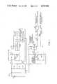
FIG. 1 is a schematic diagram of electronic cerebral palsy treatment apparatus embodying the principles of the present invention; and
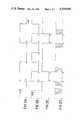
FIGS. 2A through 2D are wave forms illustrating the operation of the FIG. 1 apparatus.
Cerebral palsy may be defined as a disability resulting from damage to the brain before, during or after birth which is outwardly manifested by muscular incoordination and speech disturbances. Prenatal injury may be caused by a variety of factors, including diabetes, encephalocele, erythroblastosis, hydrocephalus, microcephaly, rubella, toxemia, toxoplasmosis or heredity. Postnatal injury may result from concussions, encephalitis, infection, lead poisoning, sickle cell, trauma, tumor or other causes. Most often, however, the damage which causes cerebral palsy occurs at birth; those cases are the result of anoxia, breech birth, dystocia, prematurity, respiratory distress or other causes. See O'Reilly, D. E., Walentynowic, J. E.: Etiological Factors in Cerebral Palsy: An Historical Review, Develop Med. Child Neurol. 1981; 23:633-642.
The apparatus of the instant invention has been found to relieve the symptoms of cerebral palsy in all subjects and to produce dramatic results with a relatively low level current and without chemical intervention.
To illustrate performance of the instant invention in overview, the apparatus of FIG. 1 is utilized to treat the symptoms associated with the diseased state of a patient who is suffering from cerebral palsy. A first positive contact electrode 60 (FIG. 1) is placed on cervical spinous process. A second negative contact electrode 72 (FIG. 1) is placed at each affected muscle. The treatments should be for 20 minutes. In addition, the first positive contact may be placed at the occiput of the head and the second negative contact may be submerged in the bath tub for the patient's daily relaxation.
An electronic wave (depicted in FIG. 2D) is applied between thefirst electrode 60, and theelectrode 72 which are connected on common. The wave form of FIG. 2D comprises a low level (less than 4 milliamperes) pulse train of relatively high frequency, e.g., between 12 and 20 khz modulated in amplitude by a relatively low frequency wave in the range of 8 to 20 hz. The low frequency wave is preferably non-symmetrical (that shown in FIG. 2D), for example characterized by a 3:1 duty cycle, being on three quarters of the time and off one quarter of the recurring period. For concreteness only and without limitation, it will hereinafter be assumed that the high frequency pulse occurs at a 15 khz rate and 1-1.5 m.a. level, while being subject to a 15 hz modulation with a 3:1 duty factor.
I have found that the wave of FIG. 2D is effective to block the pain perceived and relieve the symptoms associated with cerebral palsy. One can see a gradual increase in the patient's motor function which is accompanied by alleviation of pain.
The particular mechanism causing elimination of the symptoms of cerebral palsy is believed to follow from some increase in neural transmission to the muscles which is responsive to the low frequency modulation envelope introduced into the body, with the high frequency wave constituent serving as a transcutaneous carrier for the low frequency modulation, thereby increasing coordination and motor function.
While the precise operative mechanism may be the subject of debate, the fact of the relief of pain, reduction of spasticity, and increase in coordination is not.
The FIG. 1electronic apparatus 10 for generating and applying the wave form of FIG. 2D will now be specifically considered. A battery 12 is connected to a PNPseries pass transistor 18 which, in turn, selectively passes the voltage from battery 12 through avoltage regulator 20 to form the positive direct current voltage supply for theapparatus 10 electronics. The unit is first turned on by momentarily closing a power-onswitch 17. This applies a low voltage to the base ofPNP transistor 18, turning that device on and effectively coupling the potential of battery 12 to aseries pass transistor 21 in thevoltage regulator 20. Because the final output of a counter ordivider chain 27 is initially low on power turn on, the resulting high output ofinverter 35 applies a high potential to the base oftransistor 19, turning it on and thereby latchingPNP transistor 18 to its conductive condition whenswitch 17 is released. This maintains the electronic apparatus on for a desired period which is determined by the frequency of anoscillator 25 and the division factor of thedivider 27, i.e., the period required for the most significant stage of thecounter 27 to reach its high or binary "1" state. The switched power supply assures that the electronic apparatus is not inadvertently left on to unduly discharge the battery 12.
The regulated output of battery 12 applied throughPNP transistor 18 is converted to a lower regulated value by theregulator 20.Regulator 20 is per se well known and includes the seriespass PNP transistor 21 having a constant voltage applied to the base thereof by a Zener diode 24 energized by aresistor 22. The constant potential output ofregulator 20, which serves as the supply voltage for much of the remaining electronics of FIG. 1, is the characteristic reverse excitation voltage of Zener diode 24 less about 7/10 of a volt for the base-emitter drop oftransistor 21.
As above noted, the active power supply interval forcircuit 10 of the drawing is fixed and preset to a specific period. The above-discussed time out circuitry is employed to assure that the unit is not inadvertently left on. Many ways of achieving this result will be readily apparent to those skilled in the art. For example, a variable time out may be provided by employing a switch to connect the input ofinverter 35 to varying ones of the more significant stage outputs of thepulse counter chain 27. Yet further, separate electronic or electromechanical timer apparatus, fixed or variable, all per se well known, may be employed to supply a positive potential to the base oftransistor 19 for the desired "on" period; and to switch off the base drive totransistor 19, thereby turning offseries pass transistor 18, when the desired operative period has passed.
Atime base oscillator 25 supplies an input to the pulse counter ordivider chain 27. The frequency ofoscillator 25 is chosen for convenience to be an integral multiple of the pulse frequency (FIG. 2D) desired for delivery to the patient. For the assumed 15 khz desired frequency, a 30 khz oscillation repetition rate may be usefully employed foroscillator 25, such that the 15 khz signal is derived at a divide-by-two tap 28 ofdivider chain 27. The 15 khz signal is supplied as one input to aNAND gate 34, the output of which corresponds to the ultimately desired wave of FIG. 2D.Outputs divider 27 are supplied as inputs to aNAND gate 33, the output of which is supplied as a second input to theNAND gate 34. Theoutput 29 ofdivider 27 supplies the 30 hz wave of FIG. 2B (pulse division factor 1,000 at tap 29), while the 15 hz wave of FIG. 2A is supplied at a divider output 30 (divider factor: 2,000).Logic gate 33 generates the output wave of FIG. 2C, being at its high or Boolean "1" value when either of the waves of FIGS. 2A or 2B is low (i.e., preceding the time a, during the interval b-e, --and following time f). Correspondingly, during the periods a-b and e-f when the output atdivider 27 taps 29 and 30 are both high, the output ofgate 33 is low (Boolean "0" value).
The wave form of FIG. 2C is supplied as one intput to thegate 34 together with the 15 khz pulse train at the divide-by-twocounter 27 output port 28. Accordingly, the output ofNAND gate 34 switches between its high and low state during the periods when the FIG. 2C wave is high, i.e., preceding time a, during the interval b-e, following the time f, and so forth for the recurring pattern illustrated by FIGS. 2A-2D.
The voltage wave form of FIG. 2D is converted to a current in the milliampere range for application to the patient by the following circuitry of FIG. 1. As a first matter, a gated constantcurrent generator 36 passes a gated current (either off or of a fixed value) through apotentiometer 38 under control of the output of theNAND gate 34. When the output of NAND gate is low, atransistor 37 in constantcurrent generator 36 is on and a current substantially given by the positive potential output of regulator 20 (applied to the base of transistor 37) less a 7/10 of a volt base emitter drop for thetransistor 37, divided by the resistance value of theresistance 39 in the emitter circuit oftransistor 37. The voltage at the variable tap of thepotentiometer 38 is supplied to the base of aPNP transistor 43 of a constantcurrent pulse generator 40. The output ofpulse generator 40 is a current which switches between its off (zero current) state, and a value given by the voltage at thepotentiometer 38 tap, less a diode drop for the emitter-base oftransistor 43, divided by the resistance value ofresistor 42 connected in the emitter circuit of thePNP device 43. This pulsed current output ofpulse generator 40 corresponds in wave form to FIG. 2D, and is at a level, determined by the setting ofpotentiometer 38, in the low milliampere range. It is this current pulse which is ultimately delivered to the patient to provide the requisite relief of symptoms.
In a typical application the patient is provided with thepotentiometer 38. The potentiometer is first turned up so that the administered current pulses provide a noticeable tingling sensation on the patient's skin surface. The patient is then instructed to turn down the potentiometer adjustment until the sensation just disappears. This will provide the amount of transcutaneous electronic stimulation to treat the symptoms associated with the patient's disease. The potentiometer setting may be adjusted by the patient as required.
The current pulses fromgenerator 40 pass through a protective,series limiting resistor 50 to an output terminal 51. It there flows via thelead 55 connected to terminal 51 to theelectrode 60 adhered to the frontalis. The current transcutaneously passes into the patient, flows through the patient, and returns to electronic ground via theelectrode pad 72 adhered to the occiput. Alternatively,electrode 60 is adhered to the cervical spinous process andelectrode 72 to each affected muscle. In addition,electrode 60 may be adhered to the occiput of the head andelectrode 72 may be submerged in the bathtub for a daily relaxation treatment.Electrode 72 is connected to electronic system ground via lead 70 and apparatus terminal port 52a.
As above noted, the apparatus and methodology of the instant invention treats the symptoms associated with cerebral palsy. The apparatus and methodology has manifest advantages for alleviating the patient's symptoms.
The above-described arrangement and methodology are merely illustrative of the principles of the present invention. Numerous modifications and adaptations thereof will be readily apparent to those skilled in the art without departing from the spirit and scope of the present invention.
Claims (5)
1. A method for suppressing pain and reducing spasticity and other symptoms associated with cerebral palsy including the steps of securing a first electrode at the frontalis muscle, securing a second electrode connected electronically in common to the occiput of the subject's head, and supplying an electrical wave comprising a high frequency amplitude modulation to said first, and said second and third electrodes.
2. A method for suppressing pain and reducing spasticity and other symptoms associated with cerebral palsy including the steps of securing first electrode means at the cervical spinous process, securing second electrode means to each affected muscle, and supplying an electrical wave comprising a high frequency amplitude modulation to said first and said second electrode means.
3. The method as in claim 1 or 2, wherein the frequency of said high frequency electrical wave was in the range of 12-20 khz, wherein said low frequency modulation is in the range 8-20 hz, and wherein said wave does not exceed about 4 milliamperes.
4. The method as in claim 3, wherein said amplitude modulation is non-symmetrical.
5. A method for suppressing pain and reducing spasticity and other symptoms associated with cerebral palsy including the steps of securing a first electrode at the frontalis and securing a second electrode to the occiput of the head, and supplying an electrical wave comprising a high frequency amplitude modulation to said first and said second electrodes.
Priority Applications (1)
| Application Number | Priority Date | Filing Date | Title |
|---|---|---|---|
| US06/638,502US4559948A (en) | 1984-01-09 | 1984-08-07 | Cerebral palsy treatment apparatus and methodology |
Applications Claiming Priority (2)
| Application Number | Priority Date | Filing Date | Title |
|---|---|---|---|
| US06/569,476US4550733A (en) | 1984-01-09 | 1984-01-09 | Electronic dental analgesia apparatus and methodology |
| US06/638,502US4559948A (en) | 1984-01-09 | 1984-08-07 | Cerebral palsy treatment apparatus and methodology |
Related Parent Applications (1)
| Application Number | Title | Priority Date | Filing Date |
|---|---|---|---|
| US06/569,476Continuation-In-PartUS4550733A (en) | 1984-01-09 | 1984-01-09 | Electronic dental analgesia apparatus and methodology |
Publications (1)
| Publication Number | Publication Date |
|---|---|
| US4559948Atrue US4559948A (en) | 1985-12-24 |
Family
ID=27075066
Family Applications (1)
| Application Number | Title | Priority Date | Filing Date |
|---|---|---|---|
| US06/638,502Expired - Fee RelatedUS4559948A (en) | 1984-01-09 | 1984-08-07 | Cerebral palsy treatment apparatus and methodology |
Country Status (1)
| Country | Link |
|---|---|
| US (1) | US4559948A (en) |
Cited By (61)
| Publication number | Priority date | Publication date | Assignee | Title |
|---|---|---|---|---|
| US4844075A (en)* | 1984-01-09 | 1989-07-04 | Pain Suppression Labs, Inc. | Transcranial stimulation for the treatment of cerebral palsy |
| US5609617A (en)* | 1995-02-21 | 1997-03-11 | C. Norman Shealy | Method for enhancement of dehydroepiandrosterone |
| US6023642A (en)* | 1997-05-08 | 2000-02-08 | Biogenics Ii, Llc | Compact transcutaneous electrical nerve stimulator |
| US6161044A (en)* | 1998-11-23 | 2000-12-12 | Synaptic Corporation | Method and apparatus for treating chronic pain syndromes, tremor, dementia and related disorders and for inducing electroanesthesia using high frequency, high intensity transcutaneous electrical nerve stimulation |
| WO2004028624A2 (en) | 2002-09-24 | 2004-04-08 | Biocontrol Medical Ltd. | Nerve stimulation for treating spasticity, tremor, muscle weakness, and other motor disorders |
| US20040162594A1 (en)* | 2001-05-17 | 2004-08-19 | King Gary W. | Apparatus and method for blocking activation of tissue or conduction of action potentials while other tissue is being therapeutically activated |
| US20040225237A1 (en)* | 2003-02-06 | 2004-11-11 | Nola Keren | Method for treatment of patients having problems in motoric functions |
| US6907295B2 (en) | 2001-08-31 | 2005-06-14 | Biocontrol Medical Ltd. | Electrode assembly for nerve control |
| US20060106441A1 (en)* | 2004-11-15 | 2006-05-18 | Shai Ayal | Techniques for nerve stimulation |
| RU2284198C1 (en)* | 2005-03-21 | 2006-09-27 | Михаил Алексеевич Щукин | Method for treating paralyses and pareses |
| US7321793B2 (en) | 2003-06-13 | 2008-01-22 | Biocontrol Medical Ltd. | Vagal stimulation for atrial fibrillation therapy |
| US20080318314A1 (en)* | 2007-06-20 | 2008-12-25 | Valentin Fulga | Production from blood of cells of neural lineage |
| US7561922B2 (en) | 2004-12-22 | 2009-07-14 | Biocontrol Medical Ltd. | Construction of electrode assembly for nerve control |
| US7634317B2 (en) | 2001-08-31 | 2009-12-15 | Bio Control Medical (B.C.M.) Ltd. | Techniques for applying, calibrating, and controlling nerve fiber stimulation |
| US20100030299A1 (en)* | 2007-04-13 | 2010-02-04 | Alejandro Covalin | Apparatus and method for the treatment of headache |
| US7734355B2 (en) | 2001-08-31 | 2010-06-08 | Bio Control Medical (B.C.M.) Ltd. | Treatment of disorders by unidirectional nerve stimulation |
| US7778703B2 (en) | 2001-08-31 | 2010-08-17 | Bio Control Medical (B.C.M.) Ltd. | Selective nerve fiber stimulation for treating heart conditions |
| US20100291610A1 (en)* | 2006-03-08 | 2010-11-18 | Yael Porat | Regulating Stem Cells |
| US7844346B2 (en) | 2002-05-23 | 2010-11-30 | Biocontrol Medical Ltd. | Electrode assembly for nerve control |
| US7885709B2 (en) | 2001-08-31 | 2011-02-08 | Bio Control Medical (B.C.M.) Ltd. | Nerve stimulation for treating disorders |
| US7885711B2 (en) | 2003-06-13 | 2011-02-08 | Bio Control Medical (B.C.M.) Ltd. | Vagal stimulation for anti-embolic therapy |
| US7904176B2 (en) | 2006-09-07 | 2011-03-08 | Bio Control Medical (B.C.M.) Ltd. | Techniques for reducing pain associated with nerve stimulation |
| US7974693B2 (en) | 2001-08-31 | 2011-07-05 | Bio Control Medical (B.C.M.) Ltd. | Techniques for applying, configuring, and coordinating nerve fiber stimulation |
| US8060197B2 (en) | 2003-05-23 | 2011-11-15 | Bio Control Medical (B.C.M.) Ltd. | Parasympathetic stimulation for termination of non-sinus atrial tachycardia |
| US8204591B2 (en) | 2002-05-23 | 2012-06-19 | Bio Control Medical (B.C.M.) Ltd. | Techniques for prevention of atrial fibrillation |
| US8571653B2 (en) | 2001-08-31 | 2013-10-29 | Bio Control Medical (B.C.M.) Ltd. | Nerve stimulation techniques |
| US8609082B2 (en) | 2005-01-25 | 2013-12-17 | Bio Control Medical Ltd. | Administering bone marrow progenitor cells or myoblasts followed by application of an electrical current for cardiac repair, increasing blood supply or enhancing angiogenesis |
| US8685724B2 (en) | 2004-06-01 | 2014-04-01 | Kwalata Trading Limited | In vitro techniques for use with stem cells |
| US8755893B2 (en) | 2010-06-08 | 2014-06-17 | Bluewind Medical Ltd. | Tibial nerve stimulation |
| US8880192B2 (en) | 2012-04-02 | 2014-11-04 | Bio Control Medical (B.C.M.) Ltd. | Electrode cuffs |
| US9186504B2 (en) | 2010-11-15 | 2015-11-17 | Rainbow Medical Ltd | Sleep apnea treatment |
| US20160030737A1 (en)* | 2013-03-15 | 2016-02-04 | The Regents Of The University Of California | Multi-site transcutaneous electrical stimulation of the spinal cord for facilitation of locomotion |
| US9370660B2 (en) | 2013-03-29 | 2016-06-21 | Rainbow Medical Ltd. | Independently-controlled bidirectional nerve stimulation |
| US9457186B2 (en) | 2010-11-15 | 2016-10-04 | Bluewind Medical Ltd. | Bilateral feedback |
| US9517344B1 (en) | 2015-03-13 | 2016-12-13 | Nevro Corporation | Systems and methods for selecting low-power, effective signal delivery parameters for an implanted pulse generator |
| US9597521B2 (en) | 2015-01-21 | 2017-03-21 | Bluewind Medical Ltd. | Transmitting coils for neurostimulation |
| US9713707B2 (en) | 2015-11-12 | 2017-07-25 | Bluewind Medical Ltd. | Inhibition of implant migration |
| US9764146B2 (en) | 2015-01-21 | 2017-09-19 | Bluewind Medical Ltd. | Extracorporeal implant controllers |
| US9782589B2 (en) | 2015-06-10 | 2017-10-10 | Bluewind Medical Ltd. | Implantable electrostimulator for improving blood flow |
| US9861812B2 (en) | 2012-12-06 | 2018-01-09 | Blue Wind Medical Ltd. | Delivery of implantable neurostimulators |
| US10004896B2 (en) | 2015-01-21 | 2018-06-26 | Bluewind Medical Ltd. | Anchors and implant devices |
| US10105540B2 (en) | 2015-11-09 | 2018-10-23 | Bluewind Medical Ltd. | Optimization of application of current |
| US10124178B2 (en) | 2016-11-23 | 2018-11-13 | Bluewind Medical Ltd. | Implant and delivery tool therefor |
| US10137299B2 (en) | 2013-09-27 | 2018-11-27 | The Regents Of The University Of California | Engaging the cervical spinal cord circuitry to re-enable volitional control of hand function in tetraplegic subjects |
| US10653888B2 (en) | 2012-01-26 | 2020-05-19 | Bluewind Medical Ltd | Wireless neurostimulators |
| US10751533B2 (en) | 2014-08-21 | 2020-08-25 | The Regents Of The University Of California | Regulation of autonomic control of bladder voiding after a complete spinal cord injury |
| US10773074B2 (en) | 2014-08-27 | 2020-09-15 | The Regents Of The University Of California | Multi-electrode array for spinal cord epidural stimulation |
| US10806927B2 (en) | 2011-11-11 | 2020-10-20 | The Regents Of The University Of California | Transcutaneous spinal cord stimulation: noninvasive tool for activation of locomotor circuitry |
| US11097122B2 (en) | 2015-11-04 | 2021-08-24 | The Regents Of The University Of California | Magnetic stimulation of the spinal cord to restore control of bladder and/or bowel |
| US11213685B2 (en) | 2017-06-13 | 2022-01-04 | Bluewind Medical Ltd. | Antenna configuration |
| US11298533B2 (en) | 2015-08-26 | 2022-04-12 | The Regents Of The University Of California | Concerted use of noninvasive neuromodulation device with exoskeleton to enable voluntary movement and greater muscle activation when stepping in a chronically paralyzed subject |
| US11400299B1 (en) | 2021-09-14 | 2022-08-02 | Rainbow Medical Ltd. | Flexible antenna for stimulator |
| US11672982B2 (en) | 2018-11-13 | 2023-06-13 | Onward Medical N.V. | Control system for movement reconstruction and/or restoration for a patient |
| US11691015B2 (en) | 2017-06-30 | 2023-07-04 | Onward Medical N.V. | System for neuromodulation |
| US11752342B2 (en) | 2019-02-12 | 2023-09-12 | Onward Medical N.V. | System for neuromodulation |
| US11839766B2 (en) | 2019-11-27 | 2023-12-12 | Onward Medical N.V. | Neuromodulation system |
| US11992684B2 (en) | 2017-12-05 | 2024-05-28 | Ecole Polytechnique Federale De Lausanne (Epfl) | System for planning and/or providing neuromodulation |
| US12268878B2 (en) | 2017-02-17 | 2025-04-08 | The University Of British Columbia | Apparatus and methods for maintaining physiological functions |
| US12357828B2 (en) | 2017-12-05 | 2025-07-15 | Ecole Polytechnique Federale De Lausanne (Epfl) | System for planning and/or providing neuromodulation |
| US12415079B2 (en) | 2019-11-27 | 2025-09-16 | Onward Medical N.V. | Neuromodulation system |
| US12434068B2 (en) | 2017-05-23 | 2025-10-07 | The Regents Of The University Of California | Accessing spinal networks to address sexual dysfunction |
Citations (10)
| Publication number | Priority date | Publication date | Assignee | Title |
|---|---|---|---|---|
| US2004751A (en)* | 1931-03-23 | 1935-06-11 | H G Fischer & Company | Low voltage generator |
| US3640284A (en)* | 1970-01-05 | 1972-02-08 | Philip A De Langis | Apparatus for electrotherapy of the pubococcygeus |
| US3791373A (en)* | 1972-03-02 | 1974-02-12 | Univ Southern Illinois | Portable electroanesthesia device with automatic power control |
| US3902502A (en)* | 1974-09-13 | 1975-09-02 | Saul Liss | Apparatus for temporarily arresting arthritic pain |
| SU605603A1 (en)* | 1976-08-12 | 1978-05-05 | Предприятие П/Я В-8466 | Algesthesia investigation apparatus |
| US4109660A (en)* | 1977-01-05 | 1978-08-29 | Nesmeyanov Nikolai Alexandrovi | Method of tooth anesthetizing during dental treatment and device for effecting same |
| US4155366A (en)* | 1975-06-09 | 1979-05-22 | Ultra-Aids, Inc. | Method of percutaneous pain alleviation |
| US4305402A (en)* | 1979-06-29 | 1981-12-15 | Katims Jefferson J | Method for transcutaneous electrical stimulation |
| FR2500309A3 (en)* | 1981-02-25 | 1982-08-27 | Faiveley Sa | Electrical pulse generator producing analgesic effect - applies short rise time pulses, which are amplitude modulated and passed through wobbulator to affect human tissues |
| US4503863A (en)* | 1979-06-29 | 1985-03-12 | Katims Jefferson J | Method and apparatus for transcutaneous electrical stimulation |
- 1984
- 1984-08-07USUS06/638,502patent/US4559948A/ennot_activeExpired - Fee Related
Patent Citations (10)
| Publication number | Priority date | Publication date | Assignee | Title |
|---|---|---|---|---|
| US2004751A (en)* | 1931-03-23 | 1935-06-11 | H G Fischer & Company | Low voltage generator |
| US3640284A (en)* | 1970-01-05 | 1972-02-08 | Philip A De Langis | Apparatus for electrotherapy of the pubococcygeus |
| US3791373A (en)* | 1972-03-02 | 1974-02-12 | Univ Southern Illinois | Portable electroanesthesia device with automatic power control |
| US3902502A (en)* | 1974-09-13 | 1975-09-02 | Saul Liss | Apparatus for temporarily arresting arthritic pain |
| US4155366A (en)* | 1975-06-09 | 1979-05-22 | Ultra-Aids, Inc. | Method of percutaneous pain alleviation |
| SU605603A1 (en)* | 1976-08-12 | 1978-05-05 | Предприятие П/Я В-8466 | Algesthesia investigation apparatus |
| US4109660A (en)* | 1977-01-05 | 1978-08-29 | Nesmeyanov Nikolai Alexandrovi | Method of tooth anesthetizing during dental treatment and device for effecting same |
| US4305402A (en)* | 1979-06-29 | 1981-12-15 | Katims Jefferson J | Method for transcutaneous electrical stimulation |
| US4503863A (en)* | 1979-06-29 | 1985-03-12 | Katims Jefferson J | Method and apparatus for transcutaneous electrical stimulation |
| FR2500309A3 (en)* | 1981-02-25 | 1982-08-27 | Faiveley Sa | Electrical pulse generator producing analgesic effect - applies short rise time pulses, which are amplitude modulated and passed through wobbulator to affect human tissues |
Cited By (97)
| Publication number | Priority date | Publication date | Assignee | Title |
|---|---|---|---|---|
| US4844075A (en)* | 1984-01-09 | 1989-07-04 | Pain Suppression Labs, Inc. | Transcranial stimulation for the treatment of cerebral palsy |
| US5609617A (en)* | 1995-02-21 | 1997-03-11 | C. Norman Shealy | Method for enhancement of dehydroepiandrosterone |
| US6023642A (en)* | 1997-05-08 | 2000-02-08 | Biogenics Ii, Llc | Compact transcutaneous electrical nerve stimulator |
| US6161044A (en)* | 1998-11-23 | 2000-12-12 | Synaptic Corporation | Method and apparatus for treating chronic pain syndromes, tremor, dementia and related disorders and for inducing electroanesthesia using high frequency, high intensity transcutaneous electrical nerve stimulation |
| US7324853B2 (en) | 2001-04-26 | 2008-01-29 | Biocontrol Medical Ltd. | Nerve stimulation for treating spasticity, tremor, muscle weakness, and other motor disorders |
| US6892098B2 (en) | 2001-04-26 | 2005-05-10 | Biocontrol Medical Ltd. | Nerve stimulation for treating spasticity, tremor, muscle weakness, and other motor disorders |
| US20050102007A1 (en)* | 2001-04-26 | 2005-05-12 | Biocontrol Medical Ltd. | Nerve stimulation for treating spasticity, tremor, muscle weakness, and other motor disorders |
| US6928320B2 (en)* | 2001-05-17 | 2005-08-09 | Medtronic, Inc. | Apparatus for blocking activation of tissue or conduction of action potentials while other tissue is being therapeutically activated |
| US20040162594A1 (en)* | 2001-05-17 | 2004-08-19 | King Gary W. | Apparatus and method for blocking activation of tissue or conduction of action potentials while other tissue is being therapeutically activated |
| US7974693B2 (en) | 2001-08-31 | 2011-07-05 | Bio Control Medical (B.C.M.) Ltd. | Techniques for applying, configuring, and coordinating nerve fiber stimulation |
| US6907295B2 (en) | 2001-08-31 | 2005-06-14 | Biocontrol Medical Ltd. | Electrode assembly for nerve control |
| US7778703B2 (en) | 2001-08-31 | 2010-08-17 | Bio Control Medical (B.C.M.) Ltd. | Selective nerve fiber stimulation for treating heart conditions |
| US7778711B2 (en) | 2001-08-31 | 2010-08-17 | Bio Control Medical (B.C.M.) Ltd. | Reduction of heart rate variability by parasympathetic stimulation |
| US8571653B2 (en) | 2001-08-31 | 2013-10-29 | Bio Control Medical (B.C.M.) Ltd. | Nerve stimulation techniques |
| US7634317B2 (en) | 2001-08-31 | 2009-12-15 | Bio Control Medical (B.C.M.) Ltd. | Techniques for applying, calibrating, and controlling nerve fiber stimulation |
| US7346398B2 (en) | 2001-08-31 | 2008-03-18 | Bio Control Medical (B.C.M.) Ltd. | Electrode assembly for nerve control |
| US7734355B2 (en) | 2001-08-31 | 2010-06-08 | Bio Control Medical (B.C.M.) Ltd. | Treatment of disorders by unidirectional nerve stimulation |
| US8386056B2 (en) | 2001-08-31 | 2013-02-26 | Bio Control Medical (B.C.M.) Ltd. | Parasympathetic stimulation for treating atrial arrhythmia and heart failure |
| US7885709B2 (en) | 2001-08-31 | 2011-02-08 | Bio Control Medical (B.C.M.) Ltd. | Nerve stimulation for treating disorders |
| US8204591B2 (en) | 2002-05-23 | 2012-06-19 | Bio Control Medical (B.C.M.) Ltd. | Techniques for prevention of atrial fibrillation |
| US8494655B2 (en) | 2002-05-23 | 2013-07-23 | Bio Control Medical (B.C.M.) Ltd. | Electrode devices with resistive elements |
| US8725271B2 (en) | 2002-05-23 | 2014-05-13 | Bio Control Medical (B.C.M.) Ltd. | Electrode device with elongated electrode |
| US7844346B2 (en) | 2002-05-23 | 2010-11-30 | Biocontrol Medical Ltd. | Electrode assembly for nerve control |
| WO2004028624A2 (en) | 2002-09-24 | 2004-04-08 | Biocontrol Medical Ltd. | Nerve stimulation for treating spasticity, tremor, muscle weakness, and other motor disorders |
| US20040225237A1 (en)* | 2003-02-06 | 2004-11-11 | Nola Keren | Method for treatment of patients having problems in motoric functions |
| US8060197B2 (en) | 2003-05-23 | 2011-11-15 | Bio Control Medical (B.C.M.) Ltd. | Parasympathetic stimulation for termination of non-sinus atrial tachycardia |
| US7885711B2 (en) | 2003-06-13 | 2011-02-08 | Bio Control Medical (B.C.M.) Ltd. | Vagal stimulation for anti-embolic therapy |
| US7321793B2 (en) | 2003-06-13 | 2008-01-22 | Biocontrol Medical Ltd. | Vagal stimulation for atrial fibrillation therapy |
| US8685724B2 (en) | 2004-06-01 | 2014-04-01 | Kwalata Trading Limited | In vitro techniques for use with stem cells |
| US20060106441A1 (en)* | 2004-11-15 | 2006-05-18 | Shai Ayal | Techniques for nerve stimulation |
| US8909355B2 (en) | 2004-11-15 | 2014-12-09 | Bio Control Medical (B.C.M.) Ltd. | Techniques for nerve stimulation |
| US7627384B2 (en) | 2004-11-15 | 2009-12-01 | Bio Control Medical (B.C.M.) Ltd. | Techniques for nerve stimulation |
| US8326438B2 (en) | 2004-11-15 | 2012-12-04 | Bio Control Medical (B.C.M.) Ltd. | Techniques for nerve stimulation |
| US7561922B2 (en) | 2004-12-22 | 2009-07-14 | Biocontrol Medical Ltd. | Construction of electrode assembly for nerve control |
| US8609082B2 (en) | 2005-01-25 | 2013-12-17 | Bio Control Medical Ltd. | Administering bone marrow progenitor cells or myoblasts followed by application of an electrical current for cardiac repair, increasing blood supply or enhancing angiogenesis |
| RU2284198C1 (en)* | 2005-03-21 | 2006-09-27 | Михаил Алексеевич Щукин | Method for treating paralyses and pareses |
| US8541232B2 (en) | 2006-03-08 | 2013-09-24 | Kwalata Trading Limited | Composition comprising a progenitor/precursor cell population |
| US10358629B2 (en) | 2006-03-08 | 2019-07-23 | Kwalata Trading Limited | Regulating stem cells |
| US20100291610A1 (en)* | 2006-03-08 | 2010-11-18 | Yael Porat | Regulating Stem Cells |
| US9234173B2 (en) | 2006-03-08 | 2016-01-12 | Kwalata Trading Ltd. | Regulating stem cells |
| US8571651B2 (en) | 2006-09-07 | 2013-10-29 | Bio Control Medical (B.C.M.) Ltd. | Techniques for reducing pain associated with nerve stimulation |
| US7904176B2 (en) | 2006-09-07 | 2011-03-08 | Bio Control Medical (B.C.M.) Ltd. | Techniques for reducing pain associated with nerve stimulation |
| US8560075B2 (en) | 2007-04-13 | 2013-10-15 | Alejandro Covalin | Apparatus and method for the treatment of headache |
| US20100030299A1 (en)* | 2007-04-13 | 2010-02-04 | Alejandro Covalin | Apparatus and method for the treatment of headache |
| US20080318314A1 (en)* | 2007-06-20 | 2008-12-25 | Valentin Fulga | Production from blood of cells of neural lineage |
| US8755893B2 (en) | 2010-06-08 | 2014-06-17 | Bluewind Medical Ltd. | Tibial nerve stimulation |
| US9186504B2 (en) | 2010-11-15 | 2015-11-17 | Rainbow Medical Ltd | Sleep apnea treatment |
| US9457186B2 (en) | 2010-11-15 | 2016-10-04 | Bluewind Medical Ltd. | Bilateral feedback |
| US10806927B2 (en) | 2011-11-11 | 2020-10-20 | The Regents Of The University Of California | Transcutaneous spinal cord stimulation: noninvasive tool for activation of locomotor circuitry |
| US12059571B2 (en) | 2012-01-26 | 2024-08-13 | Bluewind Medical Ltd | Wireless neurostimulators |
| US11648410B2 (en) | 2012-01-26 | 2023-05-16 | Bluewind Medical Ltd. | Wireless neurostimulators |
| US10653888B2 (en) | 2012-01-26 | 2020-05-19 | Bluewind Medical Ltd | Wireless neurostimulators |
| US8880192B2 (en) | 2012-04-02 | 2014-11-04 | Bio Control Medical (B.C.M.) Ltd. | Electrode cuffs |
| US11464966B2 (en) | 2012-12-06 | 2022-10-11 | Bluewind Medical Ltd. | Delivery of implantable neurostimulators |
| US11278719B2 (en) | 2012-12-06 | 2022-03-22 | Bluewind Medical Ltd. | Delivery of implantable neurostimulators |
| US9861812B2 (en) | 2012-12-06 | 2018-01-09 | Blue Wind Medical Ltd. | Delivery of implantable neurostimulators |
| US10238863B2 (en) | 2012-12-06 | 2019-03-26 | Bluewind Medical Ltd. | Delivery of implantable neurostimulators |
| US20160030737A1 (en)* | 2013-03-15 | 2016-02-04 | The Regents Of The University Of California | Multi-site transcutaneous electrical stimulation of the spinal cord for facilitation of locomotion |
| US12311169B2 (en) | 2013-03-15 | 2025-05-27 | The Regents Of The University Of California | Multi-site transcutaneous electrical stimulation of the spinal cord for facilitation of locomotion |
| US9993642B2 (en)* | 2013-03-15 | 2018-06-12 | The Regents Of The University Of California | Multi-site transcutaneous electrical stimulation of the spinal cord for facilitation of locomotion |
| US11400284B2 (en) | 2013-03-15 | 2022-08-02 | The Regents Of The University Of California | Method of transcutaneous electrical spinal cord stimulation for facilitation of locomotion |
| US9370660B2 (en) | 2013-03-29 | 2016-06-21 | Rainbow Medical Ltd. | Independently-controlled bidirectional nerve stimulation |
| US11123312B2 (en) | 2013-09-27 | 2021-09-21 | The Regents Of The University Of California | Engaging the cervical spinal cord circuitry to re-enable volitional control of hand function in tetraplegic subjects |
| US12076301B2 (en) | 2013-09-27 | 2024-09-03 | The Regents Of The University Of California | Engaging the cervical spinal cord circuitry to re-enable volitional control of hand function in tetraplegic subjects |
| US10137299B2 (en) | 2013-09-27 | 2018-11-27 | The Regents Of The University Of California | Engaging the cervical spinal cord circuitry to re-enable volitional control of hand function in tetraplegic subjects |
| US10751533B2 (en) | 2014-08-21 | 2020-08-25 | The Regents Of The University Of California | Regulation of autonomic control of bladder voiding after a complete spinal cord injury |
| US10773074B2 (en) | 2014-08-27 | 2020-09-15 | The Regents Of The University Of California | Multi-electrode array for spinal cord epidural stimulation |
| US10004896B2 (en) | 2015-01-21 | 2018-06-26 | Bluewind Medical Ltd. | Anchors and implant devices |
| US9764146B2 (en) | 2015-01-21 | 2017-09-19 | Bluewind Medical Ltd. | Extracorporeal implant controllers |
| US9597521B2 (en) | 2015-01-21 | 2017-03-21 | Bluewind Medical Ltd. | Transmitting coils for neurostimulation |
| US9517344B1 (en) | 2015-03-13 | 2016-12-13 | Nevro Corporation | Systems and methods for selecting low-power, effective signal delivery parameters for an implanted pulse generator |
| US9937348B1 (en) | 2015-03-13 | 2018-04-10 | Nevro Corp. | Systems and methods for selecting low-power, effective signal delivery parameters for an implanted pulse generator |
| US10780276B1 (en) | 2015-03-13 | 2020-09-22 | Nevro Corp. | Systems and methods for selecting low-power, effective signal delivery parameters for an implanted pulse generator |
| US10369366B2 (en) | 2015-06-10 | 2019-08-06 | Bluewind Medical Ltd. | Implantable electrostimulator for improving blood flow |
| US9782589B2 (en) | 2015-06-10 | 2017-10-10 | Bluewind Medical Ltd. | Implantable electrostimulator for improving blood flow |
| US11298533B2 (en) | 2015-08-26 | 2022-04-12 | The Regents Of The University Of California | Concerted use of noninvasive neuromodulation device with exoskeleton to enable voluntary movement and greater muscle activation when stepping in a chronically paralyzed subject |
| US11097122B2 (en) | 2015-11-04 | 2021-08-24 | The Regents Of The University Of California | Magnetic stimulation of the spinal cord to restore control of bladder and/or bowel |
| US11116975B2 (en) | 2015-11-09 | 2021-09-14 | Bluewind Medical Ltd. | Optimization of application of current |
| US11612747B2 (en) | 2015-11-09 | 2023-03-28 | Bluewind Medical Ltd. | Optimization of application of current |
| US10105540B2 (en) | 2015-11-09 | 2018-10-23 | Bluewind Medical Ltd. | Optimization of application of current |
| US9713707B2 (en) | 2015-11-12 | 2017-07-25 | Bluewind Medical Ltd. | Inhibition of implant migration |
| US10449374B2 (en) | 2015-11-12 | 2019-10-22 | Bluewind Medical Ltd. | Inhibition of implant migration |
| US10744331B2 (en) | 2016-11-23 | 2020-08-18 | Bluewind Medical Ltd. | Implant and delivery tool therefor |
| US10124178B2 (en) | 2016-11-23 | 2018-11-13 | Bluewind Medical Ltd. | Implant and delivery tool therefor |
| US11439833B2 (en) | 2016-11-23 | 2022-09-13 | Bluewind Medical Ltd. | Implant-delivery tool |
| US12268878B2 (en) | 2017-02-17 | 2025-04-08 | The University Of British Columbia | Apparatus and methods for maintaining physiological functions |
| US12434068B2 (en) | 2017-05-23 | 2025-10-07 | The Regents Of The University Of California | Accessing spinal networks to address sexual dysfunction |
| US11213685B2 (en) | 2017-06-13 | 2022-01-04 | Bluewind Medical Ltd. | Antenna configuration |
| US11951316B2 (en) | 2017-06-13 | 2024-04-09 | Bluewind Medical Ltd. | Antenna configuration |
| US11691015B2 (en) | 2017-06-30 | 2023-07-04 | Onward Medical N.V. | System for neuromodulation |
| US11992684B2 (en) | 2017-12-05 | 2024-05-28 | Ecole Polytechnique Federale De Lausanne (Epfl) | System for planning and/or providing neuromodulation |
| US12357828B2 (en) | 2017-12-05 | 2025-07-15 | Ecole Polytechnique Federale De Lausanne (Epfl) | System for planning and/or providing neuromodulation |
| US11672982B2 (en) | 2018-11-13 | 2023-06-13 | Onward Medical N.V. | Control system for movement reconstruction and/or restoration for a patient |
| US11752342B2 (en) | 2019-02-12 | 2023-09-12 | Onward Medical N.V. | System for neuromodulation |
| US11839766B2 (en) | 2019-11-27 | 2023-12-12 | Onward Medical N.V. | Neuromodulation system |
| US12415079B2 (en) | 2019-11-27 | 2025-09-16 | Onward Medical N.V. | Neuromodulation system |
| US11400299B1 (en) | 2021-09-14 | 2022-08-02 | Rainbow Medical Ltd. | Flexible antenna for stimulator |
Similar Documents
| Publication | Publication Date | Title |
|---|---|---|
| US4559948A (en) | Cerebral palsy treatment apparatus and methodology | |
| US4627438A (en) | Electronic migraine modulator apparatus and methodology | |
| US4550733A (en) | Electronic dental analgesia apparatus and methodology | |
| US4856526A (en) | Apparatus and methodology for treatment of headache syndromes | |
| US4175551A (en) | Electrical massage device | |
| US4431002A (en) | Modulated deep afferent stimulator | |
| JPS6036291Y2 (en) | Arthritis pain suppression device | |
| US5052391A (en) | High frequency high intensity transcutaneous electrical nerve stimulator and method of treatment | |
| CA1319174C (en) | Electrical nerve stimulation device for nausea control | |
| US5487759A (en) | Nerve stimulating device and associated support device | |
| US6351674B2 (en) | Method for inducing electroanesthesia using high frequency, high intensity transcutaneous electrical nerve stimulation | |
| US6161044A (en) | Method and apparatus for treating chronic pain syndromes, tremor, dementia and related disorders and for inducing electroanesthesia using high frequency, high intensity transcutaneous electrical nerve stimulation | |
| US4784142A (en) | Methodology for electronic dental analgesia | |
| US4614193A (en) | Electronic glaucoma treatment apparatus and methodology | |
| US4586509A (en) | Temporomandibular joint-myofascial pain dysfunction syndrome treatment apparatus and methodology | |
| US4453548A (en) | Method of improving sensory tolerance with modulated nerve stimulator | |
| JPH03505051A (en) | Method and device for generating electrical pulses for biological stimulation | |
| CN109125921B (en) | Pulse acupuncture therapeutic instrument based on induced electroencephalogram signals | |
| CN110152189B (en) | Electrotherapy device capable of gradually increasing stimulation intensity | |
| US6282443B1 (en) | Method of treatment of dysmenorrhea or relieving menstrual cramps | |
| KR102334179B1 (en) | Mask pack system including electrical stimulation device | |
| US4442839A (en) | Method of modulating energy in train of electrical pulses | |
| US4574808A (en) | Apparatus and method for relieving symptoms of multiple sclerosis | |
| EP1911491A1 (en) | Healthcare device for electrostimulation | |
| US20190314626A1 (en) | Apparatus for outputting electric stimulation pulses |
Legal Events
| Date | Code | Title | Description |
|---|---|---|---|
| AS | Assignment | Owner name:PAIN SUPPRESSION LABS, INC., 559 RIVER DRIVE ELMWO Free format text:ASSIGNMENT OF ASSIGNORS INTEREST.;ASSIGNORS:LISS, SAUL;LISS, BERNARD;REEL/FRAME:004314/0541 Effective date:19840730 Owner name:PAIN SUPPRESSION LABS, INC., A CORP OF NEW JERSEY, Free format text:ASSIGNMENT OF ASSIGNORS INTEREST;ASSIGNORS:LISS, SAUL;LISS, BERNARD;REEL/FRAME:004314/0541 Effective date:19840730 | |
| FEPP | Fee payment procedure | Free format text:PAYOR NUMBER ASSIGNED (ORIGINAL EVENT CODE: ASPN); ENTITY STATUS OF PATENT OWNER: SMALL ENTITY | |
| FPAY | Fee payment | Year of fee payment:4 | |
| REMI | Maintenance fee reminder mailed | ||
| LAPS | Lapse for failure to pay maintenance fees | ||
| FP | Lapsed due to failure to pay maintenance fee | Effective date:19931226 | |
| STCH | Information on status: patent discontinuation | Free format text:PATENT EXPIRED DUE TO NONPAYMENT OF MAINTENANCE FEES UNDER 37 CFR 1.362 |