US4559805A - Hand seamer - Google Patents
Hand seamerDownload PDFInfo
- Publication number
- US4559805A US4559805AUS06/655,623US65562384AUS4559805AUS 4559805 AUS4559805 AUS 4559805AUS 65562384 AUS65562384 AUS 65562384AUS 4559805 AUS4559805 AUS 4559805A
- Authority
- US
- United States
- Prior art keywords
- seam
- body elements
- tool
- double
- anvil
- Prior art date
- Legal status (The legal status is an assumption and is not a legal conclusion. Google has not performed a legal analysis and makes no representation as to the accuracy of the status listed.)
- Expired - Lifetime
Links
- 238000004826seamingMethods0.000claimsabstractdescription37
- 238000009434installationMethods0.000claimsabstractdescription4
- 230000000295complement effectEffects0.000claims4
- 238000003825pressingMethods0.000claims4
- 230000013011matingEffects0.000claims2
- 238000010276constructionMethods0.000description10
- 239000002184metalSubstances0.000description6
- 238000005452bendingMethods0.000description3
- 238000000034methodMethods0.000description2
- 238000012986modificationMethods0.000description2
- 230000004048modificationEffects0.000description2
- 238000002788crimpingMethods0.000description1
- 230000000694effectsEffects0.000description1
- 238000007667floatingMethods0.000description1
Images


Classifications
- B—PERFORMING OPERATIONS; TRANSPORTING
- B21—MECHANICAL METAL-WORKING WITHOUT ESSENTIALLY REMOVING MATERIAL; PUNCHING METAL
- B21D—WORKING OR PROCESSING OF SHEET METAL OR METAL TUBES, RODS OR PROFILES WITHOUT ESSENTIALLY REMOVING MATERIAL; PUNCHING METAL
- B21D39/00—Application of procedures in order to connect objects or parts, e.g. coating with sheet metal otherwise than by plating; Tube expanders
- B21D39/02—Application of procedures in order to connect objects or parts, e.g. coating with sheet metal otherwise than by plating; Tube expanders of sheet metal by folding, e.g. connecting edges of a sheet to form a cylinder
- B21D39/025—Hand tools
- Y—GENERAL TAGGING OF NEW TECHNOLOGICAL DEVELOPMENTS; GENERAL TAGGING OF CROSS-SECTIONAL TECHNOLOGIES SPANNING OVER SEVERAL SECTIONS OF THE IPC; TECHNICAL SUBJECTS COVERED BY FORMER USPC CROSS-REFERENCE ART COLLECTIONS [XRACs] AND DIGESTS
- Y10—TECHNICAL SUBJECTS COVERED BY FORMER USPC
- Y10T—TECHNICAL SUBJECTS COVERED BY FORMER US CLASSIFICATION
- Y10T29/00—Metal working
- Y10T29/53—Means to assemble or disassemble
- Y10T29/53709—Overedge assembling means
Definitions
- This inventionrelates generally to apparatus for seaming the edges of roof panels together during initial construction of a building roof.
- a common problem with seaming devices for roof constructionis that obstructions near the beginning of such seam, and/or at the end of such seam, can prevent the effective operation of a conventional type seaming machine.
- the roofin order for the roof to be watertight and completely finished, it is absolutely necessary that the seams be completed for the entire length of the respective roof panels.
- Another common problem of known type seaming devicesis that they fail to properly form a double seam type construction as is necessary with assignee's MR-24 type roof.
- None of these patentsdisclose a tool for double seaming flanges between roof panels at the very start or very end of the seaming of same for either new construction and/or the re-roofing market.
- U.S. Pat. No. 1,692,954 to Roughanshows a tool for applying clamps to a pair of bars
- Wobbe U.S. Pat. No. 2,119,032shows apparatus for bending the edges of a metal plate.
- Demmin U.S. Pat. No. 2,159,784shows a tool for forming Pittsburgh joints between metal sheets.
- An object of the present inventionis to provide a hand seamer for use in making double seam connections between adjacent metal roof panels at the very beginning or end of such seams. Oftentimes, obstructions and the like exist at the very beginning or ending of the roof panel seams, and in such cases conventional type seaming apparatus cannot effectively be used.
- Another object of this inventionis to provide a relatively fast and easy, and yet very efficient and accurate, hand seaming tool for use in forming double seams for the 18" to 24" length at the beginning or at the end of roof panel construction.
- a further object of this inventionis to provide an uncomplicated, fairly inexpensive tool for quickly and yet accurately forming double seams at the beginning and end of roof panel construction, and especially where such ends are adjacent obstructions.
- a still further object of this inventionis to provide a seaming tool which can be used by hand for forming a complete double seam in a minimum number of steps for initial and finalization of roof construction seams where a motor driven seamer is used for forming the main portions of the double seam.
- the present inventionis for a hand tool which has a pair of anvil heads in plier-type actuating and clamping frame with handle members for actuating the mechanism to open and close the anvil heads. Suitable actuation of the heads will form the initial seam between two adjacent flanges of roof panels. Then, by actuating a brake lever, a forming bar can be suitably rotated to bend the first seam through approximately 120° to form the initial start of the double seam. Then again, the anvil heads can be clamped together for completing the double seaming of the panel edges.
- This toolis especially useful for the initial 18" of roof panel installation with assignee's panels specifically designated as type MR-24. It has been discovered in actual practice that such roof panels, when being installed adjacent an obstruction, and especially during re-roofing operations where additional buildings or other type obstructions are closely adjacent one end of the roof edge, or in some cases both ends, it is almost impossible to use assignee's motor operated roof seamer. In such cases, it is imperative that some way of seaming the initial or final 18" of the roof seam be made possible. The present invention very effectively accomplishes this purpose.
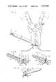
- FIG. 1is a schematic showing of a roof panel with assignee's motorized roof seamer together with the tool of the present invention.
- FIG. 2Ais a perspective view of the hand seamer of the present invention, while FIG. 2B is an exploded perspective of same.
- FIG. 3is a front elevational view of the hand seamer of the present invention.
- FIG. 4is a side elevation showing the tool as in use at the very beginning of a seaming operation.
- FIG. 5shows a portion of the tool of FIG. 4 at the end of step 1 of the seaming operation.
- FIG. 6shows a similar portion of the tool at the end of step 2 of the seaming operation.
- FIG. 7shows a fragmentary portion of an end of the forming bar.
- FIGS. 8, 9 and 10show various phases of step 2 of the seaming operation.
- FIG. 11shows the tool at the completion of step 3 of the seaming operation.
- reference numeral 10indiates in general the hand seamer of the present invention.
- an abutment or obstruction 12exists at the upslope edge of a roof.
- a roof panel 14is shown having a flange FL2 abutting the flange FL1 (FIG. 5) of the next adjacent panel.
- a ROOF RUNNER seamerwhich is a proprietary item of the assignee of the present application, is shown having a motor 16 and actuating cam and base structure 18.
- This ROOF RUNNERas described in assignee's previous patents, generally and normally is used to double seam the roof panel flanges.
- an obstructionsuch as indicated at 12 at the left of FIG. 1, is present at either the beginning or ending of the double seam. In FIG. 1, as shown, the obstruction is present at the upslope end of the seaming operation. With such a typical obstruction, the hand seamer of the present invention is especially useful.
- a double pair of body elements 20 and 30normally are pivotally engaged by the interleaved projections 22 and 32 from the respective elements.
- a pin 123normally connects each of the respective pairs of body elements together so that they can pivot with respect to each other.
- Lock rings 223keep the pin in place once mounted.
- the upper portions of the respective body elementsconnect with double pairs of actuating members 28 and 38, respectively, through suitable interconnected projections with apertures AP and pins 123.
- the respective body elements 28 and actuating members 38also interconnect with each other through suitable projections with apertures AP and pins 123.
- additional lock rings 223keep the latter pins in place.
- the lower ends of the double pair of body elementsare provided with anvil and forming bars.
- the body elements 20have supported therebetween a support block 47 for a forming bar 42 which is best seen in FIG. 7, each end of which has a semi-circular projection 142 which rides in a semi-circular recess 120 provided in the inner face of each body element 20.
- the pair of body elements 30have a longitudinally extending cross member anvil head 32.
- This anvil head 32has a flange lip engaging face 132 and a tapered channel recess 34 with sloping shoulders 35 in the upper surface thereof.
- the forming bar 42is provided with an actuating tube 40 attached near the mid-portion thereof.
- the actuating tube 40is provided longitudinally therethrough with a brake release rod 52.
- the rod 52has an enlarged head portion 50 with a spring 54 normally biasing the release bar in the outward, brake engaging position.
- a latch plate 62is pivotally mounted by pin 152 to the brake rod 52.
- a slot 252 at the inner end of brake rod 52receives the latch plate 62 therebetween.
- the latch plate 62is pivotally mounted by pin 162 from the actuating tube 40.
- the projections 78 and 88 from the actuating members 28 and 38receive the lower ends of handle tubes 26 and 36, respectively.
- a pair of handle tubes 26 and a pair 36are provided, with the other ends thereof ending in traverse cross handles 66 and 76.
- each of the pair of handle elements 26are provided with nuts 126 welded thereto for receiving adjusting screws 127.
- the adjusting screws 127are used to limit the amount of closing between the respective pairs of handles.
- Locknuts 128secure the adjustment once made.
- the actuating members 28 and 38have adjusting screws 137 and locknuts 138 provided therewith. The screws 137 are appropriately threaded T and engage with internal tapped apertures 238 within members 38.
- each screw 137engages a floating pin 237 which is used between each adjusting screw and the respective pivot pins 123 to permit accurate adjustments to be made. These screws determine the amount of force which can be effected by the anvil head 132 and the forming bar 42 against the respective roof panel seams.
- FIGS. 4-6 and 8-11the respective steps of the double seam hand-seaming operation will be described.
- two roof panels RPhave their respective edges abutting each other.
- One flange FL1has a closed lip L provided therewith, while the other flange FL2 has an open hem lip H provided therewith.
- the two flangesupon initial installation, are as depicted in this view.
- the hand seamer of this inventionis mounted, either at the initial portion of the seam or the final portion of the seam, with a space indicated by X in FIG. 4, so that the anvil head 32 and its face 132 engage with the edge of lip H, while the forming bar 42 and the front lower edges of body elements 20 engage with the backside of the lip H.
- the handles 66 and 76toward each other, as indicated by arrows P in FIG. 4
- the anvil head and forming barwill be brought together. This is step one of the process.
- FIG. 5shows the shape of the first seam after completion of step one.
- the hem Hhas been completely closed firmly upon the lip L.
- This viewalso shows how the adjusting screws 137 function in actual operation.
- FIGS. 8-10show in greater detail and in partial cross section step two of the process.
- the anvil head 32 and the respective main body elements 20 and 30are rested upon the horizontal flange portions HF1 and HF2, as depicted in FIGS. 6 and 8.
- the brake rod 50is actuated to release the latch plate 62.
- the forming bar 42can then be rotated about its longitudinal traverse axis so that the upper portion of the first seam of the lips L and H can rotate around the tip portion 135 of the anvil head.
- FIG. 10upon finally reaching this position (also as indicated by the arrows B in FIG. 6), the double seaming operation between adjacent roof panel flanges will be substantially completed.
- the respective anvil head face 132 of anvil 32 and the forming bar 42are then used to clamp the double seam to the final completely closed position.
- the lower portion of the anvil head 32 and the bottom portion of main body elements 20 and forming bar 42rest upon the horizontal flanges HF1 and HF2, respectively of the adjacent roof panels.
- the handles 66 and 76are pushed together, (step three, arrows P) and the double seam is completed.
- step threethe double seam operation for the length of the anvil head 32 and forming bar 42 is now completed.
- the widths of these headsis approximately 6", and as shown in FIG. 1, normally three such double seaming operations are performed by hand, thus completing a length of seam of approximately 18".
- four stepscould be used, making a total length of 24"; however, in actual practice, it has been found that 18" is normally adequate.
- FIG. 1only shows the double seaming by hand of one end of the roof panels, as already mentioned, the initial end or both ends of the seaming operation can be done by hand so that the motorized ROOF RUNNER only need be used between these two hand seamed portions.
- the motorized ROOF RUNNERis preferably used to finish the small portion Z of seam between the mid-area and the final hand seamed operation, as shown in FIG. 1, after the hand seaming part has been completed.
Landscapes
- Engineering & Computer Science (AREA)
- Mechanical Engineering (AREA)
- Roof Covering Using Slabs Or Stiff Sheets (AREA)
- Conveying And Assembling Of Building Elements In Situ (AREA)
Abstract
Description
Claims (17)
Priority Applications (2)
| Application Number | Priority Date | Filing Date | Title |
|---|---|---|---|
| US06/655,623US4559805A (en) | 1984-09-28 | 1984-09-28 | Hand seamer |
| CA000491186ACA1234964A (en) | 1984-09-28 | 1985-09-20 | Hand seamer |
Applications Claiming Priority (1)
| Application Number | Priority Date | Filing Date | Title |
|---|---|---|---|
| US06/655,623US4559805A (en) | 1984-09-28 | 1984-09-28 | Hand seamer |
Publications (1)
| Publication Number | Publication Date |
|---|---|
| US4559805Atrue US4559805A (en) | 1985-12-24 |
Family
ID=24629674
Family Applications (1)
| Application Number | Title | Priority Date | Filing Date |
|---|---|---|---|
| US06/655,623Expired - LifetimeUS4559805A (en) | 1984-09-28 | 1984-09-28 | Hand seamer |
Country Status (2)
| Country | Link |
|---|---|
| US (1) | US4559805A (en) |
| CA (1) | CA1234964A (en) |
Cited By (13)
| Publication number | Priority date | Publication date | Assignee | Title |
|---|---|---|---|---|
| US5012666A (en)* | 1989-07-24 | 1991-05-07 | Chen Ching Wen | Crimp tool with adjustable jaw |
| US5065608A (en)* | 1990-08-20 | 1991-11-19 | Skelton Stuart P | Hand-operated batten seamer tool |
| US5222386A (en)* | 1992-03-05 | 1993-06-29 | Jones Jr Robert L | Hand brake |
| US20050199034A1 (en)* | 2004-03-12 | 2005-09-15 | John Price | Metal sheet punch device |
| US7104106B1 (en)* | 2003-11-03 | 2006-09-12 | Francois Loignon | Method and apparatus for forming radius bends in metal frames |
| US7596982B1 (en)* | 2008-07-02 | 2009-10-06 | Honeywell International Inc. | Apparatus and method for repairing a wheel bearing cage |
| US20090255314A1 (en)* | 2008-04-14 | 2009-10-15 | Custom Spec Engineering, Inc. | Handheld brake |
| CN102500703A (en)* | 2011-10-28 | 2012-06-20 | 常州中翔机械制造有限公司 | Manual nip machine |
| FR2980499A1 (en)* | 2011-09-23 | 2013-03-29 | Damien Roth | Method for fastening profile of gutter for collection of rainwater from roof, involves arranging flanged edge along edge of cover strip, and arranging rim between cover strip and flange by deforming of flange to form crimp |
| US9016102B2 (en) | 2013-02-19 | 2015-04-28 | Milwaukee Electric Tool Corporation | Forming hand tool |
| US11006959B2 (en)* | 2018-03-28 | 2021-05-18 | Covidien Lp | Surgical anvil assemblies for surgical stapling instruments |
| RU209579U1 (en)* | 2021-08-06 | 2022-03-17 | Игорь Сергеевич Виноградов | DEVICE FOR FORMING A DOUBLE STANDING SEMBED JOINT |
| US20220105606A1 (en)* | 2020-10-07 | 2022-04-07 | Apex Brands, Inc. | Locking Pliers With Improved Adjustmentd |
Citations (11)
| Publication number | Priority date | Publication date | Assignee | Title |
|---|---|---|---|---|
| US478723A (en)* | 1892-07-12 | Double-seam folder | ||
| US498718A (en)* | 1893-05-30 | Manufacture of metal chests | ||
| US1692954A (en)* | 1927-04-30 | 1928-11-27 | Walter F Bossert | Clamp-applying tool |
| US2002502A (en)* | 1932-12-15 | 1935-05-28 | Harry A Douglas | Swaging machine |
| US2119032A (en)* | 1936-10-26 | 1938-05-31 | William M Wobbe | Metal edging machine |
| US2159784A (en)* | 1937-07-28 | 1939-05-23 | Demmin George Edwin | Apparatus for use in forming pittsburgh joints |
| US2172351A (en)* | 1937-05-15 | 1939-09-12 | Western Electric Co | Forming tool |
| US2436278A (en)* | 1945-06-09 | 1948-02-17 | Chamberlin Company | Pivoted tool for bending the edge of a panel about a supporting flange |
| US2732744A (en)* | 1956-01-31 | kuchman etal | ||
| FR1313955A (en)* | 1961-11-23 | 1963-01-04 | Labbee Ets | Portable folding machine for standing seams, especially on sheet metal covers |
| US4072118A (en)* | 1976-12-15 | 1978-02-07 | Armco Steel Corporation | Seam crimping apparatus |
- 1984
- 1984-09-28USUS06/655,623patent/US4559805A/ennot_activeExpired - Lifetime
- 1985
- 1985-09-20CACA000491186Apatent/CA1234964A/ennot_activeExpired
Patent Citations (11)
| Publication number | Priority date | Publication date | Assignee | Title |
|---|---|---|---|---|
| US478723A (en)* | 1892-07-12 | Double-seam folder | ||
| US498718A (en)* | 1893-05-30 | Manufacture of metal chests | ||
| US2732744A (en)* | 1956-01-31 | kuchman etal | ||
| US1692954A (en)* | 1927-04-30 | 1928-11-27 | Walter F Bossert | Clamp-applying tool |
| US2002502A (en)* | 1932-12-15 | 1935-05-28 | Harry A Douglas | Swaging machine |
| US2119032A (en)* | 1936-10-26 | 1938-05-31 | William M Wobbe | Metal edging machine |
| US2172351A (en)* | 1937-05-15 | 1939-09-12 | Western Electric Co | Forming tool |
| US2159784A (en)* | 1937-07-28 | 1939-05-23 | Demmin George Edwin | Apparatus for use in forming pittsburgh joints |
| US2436278A (en)* | 1945-06-09 | 1948-02-17 | Chamberlin Company | Pivoted tool for bending the edge of a panel about a supporting flange |
| FR1313955A (en)* | 1961-11-23 | 1963-01-04 | Labbee Ets | Portable folding machine for standing seams, especially on sheet metal covers |
| US4072118A (en)* | 1976-12-15 | 1978-02-07 | Armco Steel Corporation | Seam crimping apparatus |
Cited By (16)
| Publication number | Priority date | Publication date | Assignee | Title |
|---|---|---|---|---|
| US5012666A (en)* | 1989-07-24 | 1991-05-07 | Chen Ching Wen | Crimp tool with adjustable jaw |
| US5065608A (en)* | 1990-08-20 | 1991-11-19 | Skelton Stuart P | Hand-operated batten seamer tool |
| US5222386A (en)* | 1992-03-05 | 1993-06-29 | Jones Jr Robert L | Hand brake |
| US7104106B1 (en)* | 2003-11-03 | 2006-09-12 | Francois Loignon | Method and apparatus for forming radius bends in metal frames |
| US20050199034A1 (en)* | 2004-03-12 | 2005-09-15 | John Price | Metal sheet punch device |
| US7066002B2 (en)* | 2004-03-12 | 2006-06-27 | John Price | Metal sheet punch device |
| US8028560B2 (en)* | 2008-04-14 | 2011-10-04 | Custom Spec Engineering, Inc. | Handheld brake |
| US20090255314A1 (en)* | 2008-04-14 | 2009-10-15 | Custom Spec Engineering, Inc. | Handheld brake |
| US7596982B1 (en)* | 2008-07-02 | 2009-10-06 | Honeywell International Inc. | Apparatus and method for repairing a wheel bearing cage |
| FR2980499A1 (en)* | 2011-09-23 | 2013-03-29 | Damien Roth | Method for fastening profile of gutter for collection of rainwater from roof, involves arranging flanged edge along edge of cover strip, and arranging rim between cover strip and flange by deforming of flange to form crimp |
| CN102500703A (en)* | 2011-10-28 | 2012-06-20 | 常州中翔机械制造有限公司 | Manual nip machine |
| US9016102B2 (en) | 2013-02-19 | 2015-04-28 | Milwaukee Electric Tool Corporation | Forming hand tool |
| US11006959B2 (en)* | 2018-03-28 | 2021-05-18 | Covidien Lp | Surgical anvil assemblies for surgical stapling instruments |
| US20220105606A1 (en)* | 2020-10-07 | 2022-04-07 | Apex Brands, Inc. | Locking Pliers With Improved Adjustmentd |
| US12151346B2 (en)* | 2020-10-07 | 2024-11-26 | Apex Brands, Inc. | Locking pliers with improved adjustment |
| RU209579U1 (en)* | 2021-08-06 | 2022-03-17 | Игорь Сергеевич Виноградов | DEVICE FOR FORMING A DOUBLE STANDING SEMBED JOINT |
Also Published As
| Publication number | Publication date |
|---|---|
| CA1234964A (en) | 1988-04-12 |
Similar Documents
| Publication | Publication Date | Title |
|---|---|---|
| US4559805A (en) | Hand seamer | |
| JP3089035B2 (en) | Method and apparatus for automatically inserting angle plate into horizontal duct flange | |
| US3653115A (en) | Pipe joining jack | |
| US5090101A (en) | Duct corner installation tool | |
| US5174004A (en) | Radiator clamping jig | |
| DE2546696B2 (en) | Medical stapling instrument for closing tubular organic structures such as blood vessels | |
| US4538755A (en) | Apparatus for fixing belt-fasteners or the like | |
| JPH0516514B2 (en) | ||
| US4305575A (en) | Toe-nailing clamping tool | |
| AU5936999A (en) | A stapler and method for the attachment of steel framing | |
| US4238123A (en) | Toe-nailing clamping tool | |
| US5020202A (en) | Tool to clip together sheet metal ends | |
| US20240102300A1 (en) | Adjustable Staple Track | |
| US1502191A (en) | Metal-pressing tool | |
| JPH07284B2 (en) | Steering sprinkler attachment device for conveyor belts and the like | |
| US7021108B2 (en) | Punching tool for connecting decking panels together | |
| JPS59295B2 (en) | Pipe joining equipment | |
| US7360390B2 (en) | Method for securing corner connectors within a duct section | |
| US7171836B1 (en) | Roofing panel notching, shearing, and hemming tool | |
| US4823455A (en) | Radiator crimping and decrimping tools | |
| US28901A (en) | Improvement in making eaves-troughs | |
| US4757704A (en) | Gutter swedge | |
| AU593426B2 (en) | A radiator clamping jig | |
| US449725A (en) | Isaac bales | |
| DE10112656A1 (en) | Flanging unit for use on aluminum has tilt-back jaw parallel in pre-flanging phase and controlled to maintain reverse setting angle |
Legal Events
| Date | Code | Title | Description |
|---|---|---|---|
| AS | Assignment | Owner name:BUTLER MANUFACTURING COMPANY KANSAS CITY, MO A CO Free format text:ASSIGNMENT OF ASSIGNORS INTEREST.;ASSIGNOR:MC CLURE, RICHARD R.;REEL/FRAME:004336/0390 Effective date:19841128 Owner name:BUTLER MANUFACTURING COMPANY,MISSOURI Free format text:ASSIGNMENT OF ASSIGNORS INTEREST;ASSIGNOR:MC CLURE, RICHARD R.;REEL/FRAME:004336/0390 Effective date:19841128 | |
| STCF | Information on status: patent grant | Free format text:PATENTED CASE | |
| FEPP | Fee payment procedure | Free format text:PAYOR NUMBER ASSIGNED (ORIGINAL EVENT CODE: ASPN); ENTITY STATUS OF PATENT OWNER: LARGE ENTITY | |
| FPAY | Fee payment | Year of fee payment:4 | |
| AS | Assignment | Owner name:MORGAN GUARANTY TRUST COMPANY OF NEW YORK Free format text:SECURITY INTEREST;ASSIGNOR:BUTLER MANUFACTURING COMPANY;REEL/FRAME:005252/0023 Effective date:19890824 | |
| FPAY | Fee payment | Year of fee payment:8 | |
| AS | Assignment | Owner name:BUTLER MANUFACTURING COMPANY, MISSOURI Free format text:SECURITY INTEREST;ASSIGNOR:CERTAIN BANKS AND MORGAN GUARANTY TRUST COMPANY;REEL/FRAME:007052/0953 Effective date:19940624 | |
| FPAY | Fee payment | Year of fee payment:12 |