US4559045A - Pinch valve assembly - Google Patents
Pinch valve assemblyDownload PDFInfo
- Publication number
- US4559045A US4559045AUS06/493,182US49318283AUS4559045AUS 4559045 AUS4559045 AUS 4559045AUS 49318283 AUS49318283 AUS 49318283AUS 4559045 AUS4559045 AUS 4559045A
- Authority
- US
- United States
- Prior art keywords
- tubing
- pressure plate
- pinch valve
- motor
- latch member
- Prior art date
- Legal status (The legal status is an assumption and is not a legal conclusion. Google has not performed a legal analysis and makes no representation as to the accuracy of the status listed.)
- Expired - Fee Related
Links
- 239000003182parenteral nutrition solutionSubstances0.000claimsabstractdescription7
- 230000002427irreversible effectEffects0.000claimsabstractdescription6
- 230000004044responseEffects0.000claimsdescription8
- 230000001154acute effectEffects0.000claimsdescription5
- 230000014759maintenance of locationEffects0.000claimsdescription5
- 239000012530fluidSubstances0.000claimsdescription3
- 230000007257malfunctionEffects0.000claimsdescription2
- 238000006073displacement reactionMethods0.000claims4
- 230000008878couplingEffects0.000description3
- 238000010168coupling processMethods0.000description3
- 238000005859coupling reactionMethods0.000description3
- 239000000243solutionSubstances0.000description3
- 239000007788liquidSubstances0.000description2
- 230000002441reversible effectEffects0.000description2
- 230000004913activationEffects0.000description1
- 230000027455bindingEffects0.000description1
- 230000008859changeEffects0.000description1
- 238000010276constructionMethods0.000description1
- 230000000694effectsEffects0.000description1
- 229920002457flexible plasticPolymers0.000description1
- 230000005484gravityEffects0.000description1
- 238000001802infusionMethods0.000description1
- 230000007246mechanismEffects0.000description1
- 229920000620organic polymerPolymers0.000description1
- 230000002028prematureEffects0.000description1
- 230000001105regulatory effectEffects0.000description1
Images


Classifications
- A—HUMAN NECESSITIES
- A61—MEDICAL OR VETERINARY SCIENCE; HYGIENE
- A61M—DEVICES FOR INTRODUCING MEDIA INTO, OR ONTO, THE BODY; DEVICES FOR TRANSDUCING BODY MEDIA OR FOR TAKING MEDIA FROM THE BODY; DEVICES FOR PRODUCING OR ENDING SLEEP OR STUPOR
- A61M39/00—Tubes, tube connectors, tube couplings, valves, access sites or the like, specially adapted for medical use
- A61M39/22—Valves or arrangement of valves
- A61M39/28—Clamping means for squeezing flexible tubes, e.g. roller clamps
Definitions
- This inventionrelates to an apparatus or administering parenteral solutions to medical patients.
- this applicationis directed to an improved apparatus for delivering solutions at precise rates using a pinch valve flow control assembly.
- the disposable pinch valve assembly of this inventionis designed for use with parenteral solution delivery systems employing flexible tubing. It comprises a tubing receptor housing having a mutually engagable tubing support front section and back section engagable therewith.
- the front sectionincludes a stationary pressure plate against which tubing can be pressed.
- the back sectionincludes an movable pressure plate for pressing tubing against the stationary pressure plate to reduce the cross-sectional area of the flow passageway of the tubing.
- the movable plateis displaced in response to movement of a motor-driven actuator.
- the front section and back sectionare hingedly connected along one edge and have mutually engaging, irreversible connecting means on the opposite edge thereof.
- the movable plate meanscomprises a circular plate connected by flexible web connectors to an outer rim defined by the back section.
- the back sectionhas a threaded recess for engagingly receiving an actuating connector.
- the actuating connectorhas a motor drive connector at one end and a threaded cylindrical actuator at the opposite end for engaging the threaded recess.
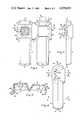
- FIG. 1is a frontal view of the disposable pinch valve housing of this invention in the open position.
- FIG. 2is a back view of the disposable pinch valve housing of this invention in the open position.
- FIG. 3is a side view of the disposable pinch valve housing of this invention in the open position.
- FIG. 4is a side view of the disposable pinch valve housing of this invention in the closed position.
- FIG. 5is a cross-sectional view taken along the line 5--5 in the representation of the open pinch valve housing shown in FIG. 1.
- FIG. 6is a cross-sectional view taken along the line 6--6 in the representation of the closed pinch valve housing shown in FIG. 4.
- FIG. 7is a cross-sectional view taken along the line 7--7 in the representation of the closed pinch valve housing shown in FIG. 4.
- FIG. 8is a cross-sectional view taken along the line 8--8 in the representation of the closed pinch valve housing shown in FIG. 4.
- FIG. 9is a cross-sectional view taken along the line 9--9 in the representation of the pinch valve housing shown in FIG. 2.
- FIG. 10is a side view of the actuating connector of this invention.
- FIG. 11is a cross-sectional view showing the actuating connector assembled with the pinch valve housing in the initial assembly position.
- FIG. 12is a cross-sectional view showing the actuating connector assembled with the back housing section after actuating movement of the connector.
- FIG. 13is a representation of the back view of the movable plate showing the web construction.
- FIG. 14is a cross-sectional view of the disposable pinch valve assembly of this invention.
- the tubing receptacle housingcomprises a front section 2 and a back section 4 joined by integral connecting hinge 6 along the common edge thereof.
- the tubingpasses into the housing through the upper passageway defined by the stationary pressure plate 8 of the front section and upper tubing passageway 10 in the back section and exits between the lower passageway defined by the lower tubing passageway 12 in the front section and the lower tubing passageway 14 in the back section.
- the movable pressure plate 16 and connector webbing associated therewithare described in greater detail hereinafter with respect to FIGS. 11, 12 and 13.
- the latch projection 18engages a retention latch described hereinafter with respect to FIG. 14.
- Snap connector meanshold the front and back housing sections in irreversible engagement once they are closed into the mutually engaging position.
- the snap connector meanscomprises latch projections 20 and 22 of the receptor section and latch receptors 24 and 26 in the support section.
- the stationary pressure plate 28has a flat surface transverse to the axis of the tubing passageways 8 and 12.
- the pressure plate 28constitutes a surface against which tubing can be pressed.
- the movable pressure plate 16when advanced against tubing held between it and the stationary pressure plate 28 pinches the tubing, reducing the cross-sectional area of the passageway therethrough.
- the rate of liquid flow through the tubingcan be controlled by regulating the distance between the movable and stationary pressure plates.
- the tubing support webbing 30having a recess 32 which positions the tubing exactly between the passageways 8 and 12 and between the pressure plates 16 and 28 when the housing is closed around a tubing section.
- FIG. 3is a side view of the disposable pinch valve housing of this invention in the open position.
- the latch projections 20 and 22have respective leading tips 34 and 36, including leading surfaces 38 and 40 which taper to projecting ribs or teeth 42 and 44 described in detail with regard to FIG. 5 hereinafter.
- the trailing surfaces 46 and 48are critical for achieving an irreversible engagement of the housing in the closed position.
- FIG. 4is a side view of the disposable pinch valve assembly of this invention in the closed position. In this view the leading surfaces 38 and 40 of the latch projections 18 and 20 can be seen in the engaged position in the latch receptors 24 and 26.
- FIG. 5is a cross-sectional view taken along the line 5--5 in FIG. 2.
- Latch projections 20can be seen to have a leading tip 34 and a rib or tooth 42 formed by the leading surface 38. This surface leads from the tip 34 to the edge of the tooth.
- the trailing surface 46 of the projectionforms a sharp and preferably an acute angle with respect to the leading surface 38.
- the latch receptor 24comprises an opening, the forward edge of which constitutes a stop 50.
- FIG. 6is a cross-sectional view of the disposable pinch valve assembly of this invention in the closed position taken along the line 6--6 in FIG. 4.
- the latch projection 20is made of flexible plastic and is deflected during closure to pass by the housing surface 56.
- the projection 20then resiliently returns to its unflexed orientation to snap into the opening of the latch receptor 24 (FIG. 5).
- Efforts to separate the housingare made difficult because the leading surface 38 of the latch projection 20 is flush with adjacent surfaces 52 and 54 of the front housing section 2.
- opening movementis prevented by the opposed surfaces of the trailing surface 46 and the stop 50.
- the hinge 6provides a hinge binding action, full closure of the sections placing the hinge under tension. If closure is incomplete, this tension forces the front and back sections into a conspicuously open position, prompting the attendant to repeat the closure step until a complete closure is effected.
- a critical function of this latch systemis to prevent removal of this disposable pinch valve assembly from tubing once it is engaged in a fully functional way. This is an inexpensive disposable unit, and repeated use would risk loss of accurate control of flow rates. Therefore, it is critical that the latching mechanism prevent reuse.
- FIG. 7is a cross-sectional view of the disposable pinch valve assembly of this invention in the closed position taken along the line 7--7 in FIG. 4.
- the relative positions of the stationary pressure plate surface 28 and the movable pressure plate surface 60can be seen.
- Tubing placed between the surfaces 28 and 60can be squeezed by moving the movable pressure plate 16 in an axial direction towards the stationary pressure plate 28.
- FIG. 8is a cross-sectional view of the disposable pinch valve assembly of this invention in a closed position taken along line 8--8 in FIG. 4.
- the webbing 30 and tubing recess 32is shown. This supports the tubing in a secure manner when engaging the two sections of the housing to maintain the tubing in a proper position between the movable pressure plate surface 60 and stationary pressure plate surface 28 until closure is complete.
- FIG. 9is a cross-sectional view of the pinch valve housing taken along the line 9--9 in FIG. 2.
- the actuating connector receptor recess 62is a cylindrical recess having female threads 64.
- a recess 66 which engages the actuating connector after assemblyis axially positioned in the center of the movable pressure plate 16.
- the retention snaps 68 and 70function to retain the actuating connector means in position after assembly as described hereinafter with respect to FIGS. 11, 12 and 13.
- FIG. 10is a side view of the actuating connector 80.
- the actuating end of the actuating connectorcomprises a cylindrical connecting end 82 having male threads 84 and a leading surface 86 with an axially central projection 88.
- Annular flange 90intermediate the connecting end 82 and the cylindrical motor drive connecting end 92 extends outwardly.
- the sloped leading surface 94forms an acute angle with the trailing surface 96 for latching engagement with snap means 68 and 70 as shown in FIG. 9.
- the motor connecting end of the actuating connector 80comprises a cylinder which is axially aligned with the connector end 82.
- a plurality of splines 98are formed in the outer surface of the cylinder surface.
- Each splinehas a tip 100 which forms an obtuse angle with the trailing edge 102.
- the tip 100forms an acute angle with the leading edge 104.
- the splines 98join at their base in an acute angle. This configuration permits easy engagement with the female splines of the motor coupler shown in FIG. 14.
- FIG. 11is a cross-sectional view of the assembled back housing section 4 and the actuating connector 80.
- the connecting end 82 of the actuating connector 80engaging the receptor recess 62.
- the projection 88is positioned to engage the recess 66 in the movable pressure plate 16.
- the trailing surface 96 of the flange 90engages the corresponding stop surface 106 of the retention snap 68 to retain the actuating connector securely in place after assembly.
- the distance between the leading face 86 and the trailing surface 96 of the actuating connectoris insufficient to force the male threads 84 into engagement with the female threads 64.
- the actuating connector 80can rotate freely after being assembled with the back housing section 4 without causing a premature engagement of the male threads 84 and female threads 64. This protects the movable pressure plate 16 and webbed connecting structure from stress and damage prior to actual use.
- FIG. 12is a cross-sectional view showing the actuator connector assembled with the back housing section after actuating movement of the connector.
- the forward actuating movement of the actuating connector 80causes engagement 85 of the male threads 84 with the female threads 64 shown in FIG. 4.
- Rotation of the actuating connector 80 about its axiscauses advancement of the projection 88 and engagement with recess 66.
- Continued advancementdisplaces movable pressure plate 16 in an axial direction.
- Reverse rotationremoves pressure on recess 66 permitting the movable pressure plate 16 to return toward its relaxed position, the webbing 108 providing the resiliency.
- FIG. 13is a detailed view of the movable pressure plate.
- the movable pressure plate 16comprises the circular central plate 110.
- the circular ring 112is connected to the central plate 110 by webs 114 and 116.
- the circular ring 112is attached to the outer rim 118 by means of webs 120 and 122.
- the webbingis constructed of flexible, resilient organic polymers and provides an elastic, flexible movement of the central plate 110 in an axial direction both toward and away from the stationary pressure plate 28.
- FIG. 14is a cross-sectional view of the fully assembled disposable pinch valve of this invention.
- the front section 2 and back section 4 of the pinch valveare closed on a suitably positioned flexible tubing 123, the tubing end 124 leading from a solution supply and the tubing end 126 leading to the patient.
- the actuating connector 80is assembled with the back section 4 of the pinch valve housing as shown in FIG. 11. The closed housing is then positioned in a recess in the motor housing 128.
- the motor connector end 92 of the actuating connector 80fits into the axially movable motor coupler 130, the splines 98 meshing with female projections 132 in a sliding engagement.
- the motor coupler 130has male projections 134 which slide in grooves 136 in the coupling wheel 138.
- the coupling wheelis mounted on the drive shaft 140 of motor 142.
- Motor 142can be any type of motor which can be controlled to move in preselected increments.
- the spring 145pushes the motor coupler and the actuating connector axially forward, the initial rotation of the coupling wheel 138 effects a threaded engagement of the threads 80 of the actuating connector 80 and threads 64 of the receptor recess.
- the initial rotation of the coupling wheel 138effects a threaded engagement of the threads 80 of the actuating connector 80 and threads 64 of the receptor recess.
- Continued rotation of wheel 138advances the projection 88 and the movable pressure plate 16 toward the stationary pressure plate 28, reducing the cross-sectional area of the tubing passageway therebetween.
- Reverse rotation of wheel 138reverses this axial movement in the direction away from the tubing, permitting the resilient tubing to return toward its relaxed configuration and increasing the cross-sectional area of the tubing passageway.
- the solenoid 144drives the projection 146 against the tubing, the end 148 thereof tightly pinching the tubing against the surface 8. This completely closes the tubing, terminating fluid flow therethrough.
- the solenoid 144can be automatically actuated in a manner known per se in the art in response to a system malfunction presenting risk to the patient.
Landscapes
- Health & Medical Sciences (AREA)
- Heart & Thoracic Surgery (AREA)
- Hematology (AREA)
- Engineering & Computer Science (AREA)
- Anesthesiology (AREA)
- Biomedical Technology (AREA)
- Life Sciences & Earth Sciences (AREA)
- Animal Behavior & Ethology (AREA)
- General Health & Medical Sciences (AREA)
- Public Health (AREA)
- Veterinary Medicine (AREA)
- Pulmonology (AREA)
- Infusion, Injection, And Reservoir Apparatuses (AREA)
- Magnetically Actuated Valves (AREA)
- Exhaust-Gas Circulating Devices (AREA)
- Orthopedics, Nursing, And Contraception (AREA)
- Medicines Containing Material From Animals Or Micro-Organisms (AREA)
- Processing Of Solid Wastes (AREA)
- External Artificial Organs (AREA)
- Containers And Packaging Bodies Having A Special Means To Remove Contents (AREA)
- Catching Or Destruction (AREA)
- Air Transport Of Granular Materials (AREA)
- Reciprocating Pumps (AREA)
- Quick-Acting Or Multi-Walled Pipe Joints (AREA)
Abstract
Description
Claims (7)
Priority Applications (14)
| Application Number | Priority Date | Filing Date | Title |
|---|---|---|---|
| US06/493,182US4559045A (en) | 1983-05-10 | 1983-05-10 | Pinch valve assembly |
| AT84303031TATE63696T1 (en) | 1983-05-10 | 1984-05-04 | PINCH VALVE ARRANGEMENT. |
| DE8484303031TDE3484605D1 (en) | 1983-05-10 | 1984-05-04 | HOSE CRUSH VALVE ARRANGEMENT. |
| EP84303031AEP0125123B1 (en) | 1983-05-10 | 1984-05-04 | Pinch valve assembly |
| CA000453711ACA1240662A (en) | 1983-05-10 | 1984-05-07 | Pinch valve assembly |
| JP59091138AJPS59211460A (en) | 1983-05-10 | 1984-05-09 | Grip valve assembly |
| MX201300AMX158839A (en) | 1983-05-10 | 1984-05-09 | IMPROVEMENTS IN DISPOSAL OF A DISPOSABLE CLAMP VALVE |
| BR8402198ABR8402198A (en) | 1983-05-10 | 1984-05-09 | DISPOSABLE THROTTLE VALVE ASSEMBLY |
| AU27856/84AAU565450B2 (en) | 1983-05-10 | 1984-05-09 | Pinch valve assembly |
| ZA843501AZA843501B (en) | 1983-05-10 | 1984-05-09 | Pinch valve assembly |
| ES532320AES8503517A1 (en) | 1983-05-10 | 1984-05-09 | Pinch valve assembly. |
| DK232884ADK232884A (en) | 1983-05-10 | 1984-05-10 | VALVE COLLECTION FOR USE IN A PLANT FOR DELIVERING PARENTAL SOLUTIONS TO PATIENTS |
| US06/613,557US4624663A (en) | 1983-05-10 | 1984-05-24 | Pinch valve assembly |
| US06/799,232US4725269A (en) | 1983-05-10 | 1985-11-18 | Crimp valve assembly |
Applications Claiming Priority (1)
| Application Number | Priority Date | Filing Date | Title |
|---|---|---|---|
| US06/493,182US4559045A (en) | 1983-05-10 | 1983-05-10 | Pinch valve assembly |
Related Child Applications (2)
| Application Number | Title | Priority Date | Filing Date |
|---|---|---|---|
| US06/613,557Continuation-In-PartUS4624663A (en) | 1983-05-10 | 1984-05-24 | Pinch valve assembly |
| US06/799,232Continuation-In-PartUS4725269A (en) | 1983-05-10 | 1985-11-18 | Crimp valve assembly |
Publications (1)
| Publication Number | Publication Date |
|---|---|
| US4559045Atrue US4559045A (en) | 1985-12-17 |
Family
ID=23959227
Family Applications (1)
| Application Number | Title | Priority Date | Filing Date |
|---|---|---|---|
| US06/493,182Expired - Fee RelatedUS4559045A (en) | 1983-05-10 | 1983-05-10 | Pinch valve assembly |
Country Status (12)
| Country | Link |
|---|---|
| US (1) | US4559045A (en) |
| EP (1) | EP0125123B1 (en) |
| JP (1) | JPS59211460A (en) |
| AT (1) | ATE63696T1 (en) |
| AU (1) | AU565450B2 (en) |
| BR (1) | BR8402198A (en) |
| CA (1) | CA1240662A (en) |
| DE (1) | DE3484605D1 (en) |
| DK (1) | DK232884A (en) |
| ES (1) | ES8503517A1 (en) |
| MX (1) | MX158839A (en) |
| ZA (1) | ZA843501B (en) |
Cited By (30)
| Publication number | Priority date | Publication date | Assignee | Title |
|---|---|---|---|---|
| US4624663A (en)* | 1983-05-10 | 1986-11-25 | Critikon, Inc. | Pinch valve assembly |
| US5147330A (en)* | 1989-10-18 | 1992-09-15 | Ljungberg & Kogel | Blood cradle |
| US5207642A (en)* | 1987-08-07 | 1993-05-04 | Baxter International Inc. | Closed multi-fluid delivery system and method |
| US5300043A (en)* | 1992-10-23 | 1994-04-05 | Smiths Industries Medical Systems, Inc. | Suction catheter valve |
| USD389228S (en) | 1996-03-19 | 1998-01-13 | Zevex, Inc. | Pinch clip occluder |
| US5810323A (en)* | 1995-03-27 | 1998-09-22 | Zevex, Inc. | Pinch clip occluder for infusion sets |
| US6142979A (en)* | 1995-03-27 | 2000-11-07 | Zevex | Pinch clip occluder system for infusion sets |
| US20020007156A1 (en)* | 2000-05-11 | 2002-01-17 | Miles Scott D. | Apparatus and method for preventing free flow in an infusion line |
| US6659976B2 (en) | 2001-04-16 | 2003-12-09 | Zevek, Inc. | Feeding set adaptor |
| US6749591B1 (en) | 1995-03-27 | 2004-06-15 | Zevex, Inc. | Pinch clip occluder system for infusion sets |
| US20040220542A1 (en)* | 2000-05-11 | 2004-11-04 | David Cise | Apparatus and method for preventing free flow in an infusion line |
| USD503799S1 (en) | 2002-09-09 | 2005-04-05 | Zevex, Inc. | In-line occluder |
| USD503978S1 (en) | 2002-09-09 | 2005-04-12 | Zevex, Inc. | In-line occluder |
| USD504506S1 (en) | 2002-06-28 | 2005-04-26 | Zevex, Inc. | Feeding pump cartridge |
| US20060084897A1 (en)* | 2004-10-14 | 2006-04-20 | Abilityone Corporation | Slide lock |
| USD536783S1 (en) | 2002-06-28 | 2007-02-13 | Zevex, Inc. | Enteral feeding pump cassette connector |
| US20080319374A1 (en)* | 2007-06-19 | 2008-12-25 | Jaime Zacharias | Post-occlusion chamber collapse canceling system for a surgical apparatus and method of use |
| US7520871B2 (en) | 2002-08-12 | 2009-04-21 | Lma North America, Inc | System and method for tension-activated fluid control |
| US7815612B2 (en) | 2000-05-11 | 2010-10-19 | Zevex, Inc. | Apparatus and method for preventing free flow in an infusion line |
| US7998121B2 (en) | 2009-02-06 | 2011-08-16 | Zevex, Inc. | Automatic safety occluder |
| USD672455S1 (en) | 2010-10-01 | 2012-12-11 | Zevex, Inc. | Fluid delivery cassette |
| US8343111B2 (en) | 2008-04-01 | 2013-01-01 | Zevex, Inc. | Anti-free flow mechanism for enteral feeding pumps |
| US8425470B2 (en) | 2008-04-01 | 2013-04-23 | Zevex, Inc. | Anti-free-flow mechanism for enteral feeding pumps |
| US8911414B2 (en) | 2010-10-01 | 2014-12-16 | Zevex, Inc. | Anti free-flow occluder and priming actuator pad |
| US9017296B2 (en) | 2008-04-01 | 2015-04-28 | Zevex, Inc. | Safety occluder and method of use |
| US20180245699A1 (en)* | 2015-08-12 | 2018-08-30 | Royal United Hospitals Bath Nhs Foundation Trust | Pinch valve for a urinary drainage system |
| CN110292692A (en)* | 2019-08-08 | 2019-10-01 | 中国人民解放军第四军医大学 | Children's oxygen supply device |
| CN112833213A (en)* | 2021-01-25 | 2021-05-25 | 山东创康生物科技有限公司 | Pinch valve |
| US11215288B2 (en)* | 2017-06-02 | 2022-01-04 | The Automation Partnership (Cambridge) Limited | Proportional pinch valve |
| US20240133472A1 (en)* | 2015-10-01 | 2024-04-25 | Repligen Corporation | Valve assembly with directional flow path |
Families Citing this family (1)
| Publication number | Priority date | Publication date | Assignee | Title |
|---|---|---|---|---|
| ATE200431T1 (en)* | 1992-10-15 | 2001-04-15 | Health Care Tech Australia | INTRAVENOUS DELIVERY SYSTEM |
Citations (6)
| Publication number | Priority date | Publication date | Assignee | Title |
|---|---|---|---|---|
| US3831625A (en)* | 1973-02-20 | 1974-08-27 | D Roediger | Intravenous safety device |
| US3915167A (en)* | 1974-05-23 | 1975-10-28 | Atlantic Design & Dev Corp | Intravenous clamp |
| US4300552A (en)* | 1978-09-01 | 1981-11-17 | Imed Corporation | Apparatus for controlling the flow of intravenous fluid to a patient |
| US4312493A (en)* | 1979-05-05 | 1982-01-26 | Stauffer Rita A | Apparatus for controlled liquid administration |
| US4337791A (en)* | 1980-11-17 | 1982-07-06 | La-Van Tech Development Corp. | Flow regulator assembly |
| US4398908A (en)* | 1980-11-28 | 1983-08-16 | Siposs George G | Insulin delivery system |
Family Cites Families (5)
| Publication number | Priority date | Publication date | Assignee | Title |
|---|---|---|---|---|
| JPS5134589A (en)* | 1974-09-14 | 1976-03-24 | Shiraimatsu Shinyaku Co | |
| AU492047B1 (en)* | 1976-05-10 | 1978-04-20 | Derby Products Pty. Ltd | Drip feed control means |
| US4105028A (en)* | 1976-10-12 | 1978-08-08 | Sadlier Patricia M | Positive control intravenous fluid administration |
| US4235412A (en)* | 1978-10-30 | 1980-11-25 | Plastronics, Inc. | Tube clamping device |
| US4375882A (en)* | 1980-10-27 | 1983-03-08 | Schreiber Jr Lloyd J | In-line flow control apparatus |
- 1983
- 1983-05-10USUS06/493,182patent/US4559045A/ennot_activeExpired - Fee Related
- 1984
- 1984-05-04EPEP84303031Apatent/EP0125123B1/ennot_activeExpired - Lifetime
- 1984-05-04ATAT84303031Tpatent/ATE63696T1/ennot_activeIP Right Cessation
- 1984-05-04DEDE8484303031Tpatent/DE3484605D1/ennot_activeExpired - Lifetime
- 1984-05-07CACA000453711Apatent/CA1240662A/ennot_activeExpired
- 1984-05-09ESES532320Apatent/ES8503517A1/ennot_activeExpired
- 1984-05-09ZAZA843501Apatent/ZA843501B/enunknown
- 1984-05-09BRBR8402198Apatent/BR8402198A/ennot_activeIP Right Cessation
- 1984-05-09AUAU27856/84Apatent/AU565450B2/ennot_activeCeased
- 1984-05-09JPJP59091138Apatent/JPS59211460A/enactiveGranted
- 1984-05-09MXMX201300Apatent/MX158839A/enunknown
- 1984-05-10DKDK232884Apatent/DK232884A/ennot_activeApplication Discontinuation
Patent Citations (6)
| Publication number | Priority date | Publication date | Assignee | Title |
|---|---|---|---|---|
| US3831625A (en)* | 1973-02-20 | 1974-08-27 | D Roediger | Intravenous safety device |
| US3915167A (en)* | 1974-05-23 | 1975-10-28 | Atlantic Design & Dev Corp | Intravenous clamp |
| US4300552A (en)* | 1978-09-01 | 1981-11-17 | Imed Corporation | Apparatus for controlling the flow of intravenous fluid to a patient |
| US4312493A (en)* | 1979-05-05 | 1982-01-26 | Stauffer Rita A | Apparatus for controlled liquid administration |
| US4337791A (en)* | 1980-11-17 | 1982-07-06 | La-Van Tech Development Corp. | Flow regulator assembly |
| US4398908A (en)* | 1980-11-28 | 1983-08-16 | Siposs George G | Insulin delivery system |
Cited By (51)
| Publication number | Priority date | Publication date | Assignee | Title |
|---|---|---|---|---|
| US4624663A (en)* | 1983-05-10 | 1986-11-25 | Critikon, Inc. | Pinch valve assembly |
| US5207642A (en)* | 1987-08-07 | 1993-05-04 | Baxter International Inc. | Closed multi-fluid delivery system and method |
| US5147330A (en)* | 1989-10-18 | 1992-09-15 | Ljungberg & Kogel | Blood cradle |
| US5300043A (en)* | 1992-10-23 | 1994-04-05 | Smiths Industries Medical Systems, Inc. | Suction catheter valve |
| US6749591B1 (en) | 1995-03-27 | 2004-06-15 | Zevex, Inc. | Pinch clip occluder system for infusion sets |
| US5810323A (en)* | 1995-03-27 | 1998-09-22 | Zevex, Inc. | Pinch clip occluder for infusion sets |
| US6142979A (en)* | 1995-03-27 | 2000-11-07 | Zevex | Pinch clip occluder system for infusion sets |
| USD389228S (en) | 1996-03-19 | 1998-01-13 | Zevex, Inc. | Pinch clip occluder |
| US7976513B2 (en) | 2000-05-11 | 2011-07-12 | Zevex, Inc. | Apparatus and method for selectively controlling flow in an infusion line |
| US6623447B2 (en) | 2000-05-11 | 2003-09-23 | Zevex, Inc. | Apparatus and method for preventing free flow in an infusion line |
| US20050283121A1 (en)* | 2000-05-11 | 2005-12-22 | David Cise | Apparatus and method for preventing free flow in an infusion line |
| US20040039347A1 (en)* | 2000-05-11 | 2004-02-26 | Scott Miles | Apparatus and method for preventing free flow in an infusion line |
| US6595950B1 (en) | 2000-05-11 | 2003-07-22 | Zevex, Inc. | Apparatus and method for preventing free flow in an infusion line |
| US20040220542A1 (en)* | 2000-05-11 | 2004-11-04 | David Cise | Apparatus and method for preventing free flow in an infusion line |
| US7815612B2 (en) | 2000-05-11 | 2010-10-19 | Zevex, Inc. | Apparatus and method for preventing free flow in an infusion line |
| US7367963B2 (en) | 2000-05-11 | 2008-05-06 | Zevex, Inc. | Apparatus and method for preventing free flow in an infusion line |
| US7150727B2 (en) | 2000-05-11 | 2006-12-19 | Zevex, Inc. | Apparatus and method for preventing free flow in an infusion line |
| US20020007156A1 (en)* | 2000-05-11 | 2002-01-17 | Miles Scott D. | Apparatus and method for preventing free flow in an infusion line |
| US20050119625A1 (en)* | 2000-05-11 | 2005-06-02 | Scott Miles | Apparatus and method for preventing free flow in an infusion line |
| US6923785B2 (en) | 2000-05-11 | 2005-08-02 | Zevex, Inc. | Apparatus and method for preventing free flow in an infusion line |
| US6979311B2 (en) | 2000-05-11 | 2005-12-27 | Zevex, Inc. | Apparatus and method for preventing free flow in an infusion line |
| US7070575B2 (en) | 2001-04-16 | 2006-07-04 | Zevex, Inc. | Adaptor for feeding sets |
| US6659976B2 (en) | 2001-04-16 | 2003-12-09 | Zevek, Inc. | Feeding set adaptor |
| US20050209552A1 (en)* | 2001-04-16 | 2005-09-22 | Beck Kent F | Adaptor for feeding sets |
| USD505199S1 (en) | 2002-06-28 | 2005-05-17 | Zevex, Inc. | Feeding pump cartridge |
| USD504506S1 (en) | 2002-06-28 | 2005-04-26 | Zevex, Inc. | Feeding pump cartridge |
| USD536783S1 (en) | 2002-06-28 | 2007-02-13 | Zevex, Inc. | Enteral feeding pump cassette connector |
| US7527608B2 (en) | 2002-08-12 | 2009-05-05 | Lma North America, Inc. | Medication infusion and aspiration system and method |
| US7520871B2 (en) | 2002-08-12 | 2009-04-21 | Lma North America, Inc | System and method for tension-activated fluid control |
| USD634005S1 (en) | 2002-09-09 | 2011-03-08 | Zevex, Inc. | In-line occluder |
| USD503978S1 (en) | 2002-09-09 | 2005-04-12 | Zevex, Inc. | In-line occluder |
| USD635664S1 (en) | 2002-09-09 | 2011-04-05 | Zevex, Inc. | In-line occluder |
| USD503799S1 (en) | 2002-09-09 | 2005-04-05 | Zevex, Inc. | In-line occluder |
| US7621883B2 (en)* | 2004-10-14 | 2009-11-24 | Patterson Medical Products, Inc. | Slide lock |
| US20060084897A1 (en)* | 2004-10-14 | 2006-04-20 | Abilityone Corporation | Slide lock |
| US20080319374A1 (en)* | 2007-06-19 | 2008-12-25 | Jaime Zacharias | Post-occlusion chamber collapse canceling system for a surgical apparatus and method of use |
| US8721594B2 (en)* | 2007-06-19 | 2014-05-13 | Alcon Research, Ltd. | Post-occlusion chamber collapse canceling system for a surgical apparatus and method of use |
| US9017296B2 (en) | 2008-04-01 | 2015-04-28 | Zevex, Inc. | Safety occluder and method of use |
| US8343111B2 (en) | 2008-04-01 | 2013-01-01 | Zevex, Inc. | Anti-free flow mechanism for enteral feeding pumps |
| US8425470B2 (en) | 2008-04-01 | 2013-04-23 | Zevex, Inc. | Anti-free-flow mechanism for enteral feeding pumps |
| US8876787B2 (en) | 2008-04-01 | 2014-11-04 | Zevex, Inc. | Anti-free-flow mechanism for enteral feeding pumps |
| US7998121B2 (en) | 2009-02-06 | 2011-08-16 | Zevex, Inc. | Automatic safety occluder |
| US8491543B2 (en) | 2009-02-06 | 2013-07-23 | Zevex, Inc. | Automatic safety occluder |
| US8911414B2 (en) | 2010-10-01 | 2014-12-16 | Zevex, Inc. | Anti free-flow occluder and priming actuator pad |
| USD672455S1 (en) | 2010-10-01 | 2012-12-11 | Zevex, Inc. | Fluid delivery cassette |
| US20180245699A1 (en)* | 2015-08-12 | 2018-08-30 | Royal United Hospitals Bath Nhs Foundation Trust | Pinch valve for a urinary drainage system |
| US10859170B2 (en)* | 2015-08-12 | 2020-12-08 | Royal United Hospitals Bath Nhs Foundation Trust | Pinch valve for a urinary drainage system |
| US20240133472A1 (en)* | 2015-10-01 | 2024-04-25 | Repligen Corporation | Valve assembly with directional flow path |
| US11215288B2 (en)* | 2017-06-02 | 2022-01-04 | The Automation Partnership (Cambridge) Limited | Proportional pinch valve |
| CN110292692A (en)* | 2019-08-08 | 2019-10-01 | 中国人民解放军第四军医大学 | Children's oxygen supply device |
| CN112833213A (en)* | 2021-01-25 | 2021-05-25 | 山东创康生物科技有限公司 | Pinch valve |
Also Published As
| Publication number | Publication date |
|---|---|
| ZA843501B (en) | 1984-12-24 |
| ATE63696T1 (en) | 1991-06-15 |
| CA1240662A (en) | 1988-08-16 |
| JPS59211460A (en) | 1984-11-30 |
| JPH0233390B2 (en) | 1990-07-26 |
| BR8402198A (en) | 1984-12-18 |
| DE3484605D1 (en) | 1991-06-27 |
| DK232884D0 (en) | 1984-05-10 |
| ES532320A0 (en) | 1985-03-16 |
| EP0125123A2 (en) | 1984-11-14 |
| ES8503517A1 (en) | 1985-03-16 |
| EP0125123A3 (en) | 1986-03-26 |
| MX158839A (en) | 1989-03-16 |
| AU565450B2 (en) | 1987-09-17 |
| DK232884A (en) | 1984-11-11 |
| AU2785684A (en) | 1984-11-15 |
| EP0125123B1 (en) | 1991-05-22 |
Similar Documents
| Publication | Publication Date | Title |
|---|---|---|
| US4559045A (en) | Pinch valve assembly | |
| US4624663A (en) | Pinch valve assembly | |
| US5634907A (en) | System for detection of fluid infusion | |
| EP0900106B1 (en) | Pinch clip occluder for infusion sets | |
| US4725269A (en) | Crimp valve assembly | |
| AU2010273694B2 (en) | Infusion cassette and set for enteral feeding pump | |
| US5439442A (en) | Device for monitoring and controlling an intravenous infusion system | |
| CA2750620C (en) | Infusion pump cassette with anti-free-flow valve mechanism | |
| CA2749557C (en) | Infusion pump cassette with anti-free-flow valve mechanism | |
| EP0686405B1 (en) | Two step IV fluid flow stop | |
| US5891096A (en) | Medicament infusion device | |
| JPS6153583B2 (en) | ||
| JPH0345657B2 (en) | ||
| WO2010088144A1 (en) | Infusion pump cassette with ant i -free -flow valve mechanism | |
| EP0365228A2 (en) | Medical laser interconnect system | |
| HK1169061A (en) | Infusion pump with infusion cassettes | |
| HK1169061B (en) | Infusion pump with infusion cassettes |
Legal Events
| Date | Code | Title | Description |
|---|---|---|---|
| AS | Assignment | Owner name:ANATROS CORPORATION 1922 JUNCTION AVE., SAN JOSE, Free format text:ASSIGNMENT OF ASSIGNORS INTEREST.;ASSIGNORS:DANBY, HAL C.;RITSON, CARL;REEL/FRAME:004144/0677 Effective date:19830617 Owner name:ANATROS CORPORATION 1922 JUNCTION AVE., SAN JOSE, Free format text:ASSIGNMENT OF ASSIGNORS INTEREST;ASSIGNORS:DANBY, HAL C.;RITSON, CARL;REEL/FRAME:004144/0677 Effective date:19830617 | |
| AS | Assignment | Owner name:AMERICAN HOSPITAL SUPPLY CORPORATION, ONE AMERICAN Free format text:ASSIGNMENT OF ASSIGNORS INTEREST.;ASSIGNOR:ANATROS CORPORATION;REEL/FRAME:004491/0866 Effective date:19851126 | |
| AS | Assignment | Owner name:CRITIKON, INC. (CRITIKON), 4110 GEORGE ROAD, TAMPA Free format text:ASSIGNMENT OF ASSIGNORS INTEREST.;ASSIGNOR:AMERICAN HOSPITAL SUPPLY CORPORATION;REEL/FRAME:004518/0900 Effective date:19860131 Owner name:CRITIKON, INC. (CRITIKON), A CORP. OF NEW JERSEY,F Free format text:ASSIGNMENT OF ASSIGNORS INTEREST;ASSIGNOR:AMERICAN HOSPITAL SUPPLY CORPORATION;REEL/FRAME:004518/0900 Effective date:19860131 | |
| FEPP | Fee payment procedure | Free format text:PAYOR NUMBER ASSIGNED (ORIGINAL EVENT CODE: ASPN); ENTITY STATUS OF PATENT OWNER: LARGE ENTITY Free format text:PAT HLDR NO LONGER CLAIMS SMALL ENT STAT AS SMALL BUSINESS (ORIGINAL EVENT CODE: LSM2); ENTITY STATUS OF PATENT OWNER: LARGE ENTITY | |
| FPAY | Fee payment | Year of fee payment:4 | |
| AS | Assignment | Owner name:FRESENIUS USA, INC., CO. OF MA Free format text:ASSIGNMENT OF ASSIGNORS INTEREST.;ASSIGNOR:CRITIKON, INC., A CORP. OF FL;REEL/FRAME:006353/0024 Effective date:19920824 Owner name:FRESENIUS AKTIENGESELLSCHAFT Free format text:ASSIGNMENT OF ASSIGNORS INTEREST.;ASSIGNOR:CRITIKON, INC., A CORP. OF FL;REEL/FRAME:006353/0024 Effective date:19920824 | |
| FEPP | Fee payment procedure | Free format text:PAYER NUMBER DE-ASSIGNED (ORIGINAL EVENT CODE: RMPN); ENTITY STATUS OF PATENT OWNER: LARGE ENTITY | |
| AS | Assignment | Owner name:FRESENIUS USA, INC. AND FRESENIUS AKTIENGESELLSCHA Free format text:ASSIGNMENT OF ASSIGNORS INTEREST.;ASSIGNOR:CRITIKON, INC.;REEL/FRAME:006364/0332 Effective date:19920824 | |
| FPAY | Fee payment | Year of fee payment:8 | |
| REMI | Maintenance fee reminder mailed | ||
| LAPS | Lapse for failure to pay maintenance fees | ||
| FP | Lapsed due to failure to pay maintenance fee | Effective date:19971217 | |
| STCH | Information on status: patent discontinuation | Free format text:PATENT EXPIRED DUE TO NONPAYMENT OF MAINTENANCE FEES UNDER 37 CFR 1.362 |