US4559044A - Volumetric metering unit for intravenous fluid addition - Google Patents
Volumetric metering unit for intravenous fluid additionDownload PDFInfo
- Publication number
- US4559044A US4559044AUS06/404,811US40481182AUS4559044AUS 4559044 AUS4559044 AUS 4559044AUS 40481182 AUS40481182 AUS 40481182AUS 4559044 AUS4559044 AUS 4559044A
- Authority
- US
- United States
- Prior art keywords
- valve
- entry
- exit
- fluid
- valves
- Prior art date
- Legal status (The legal status is an assumption and is not a legal conclusion. Google has not performed a legal analysis and makes no representation as to the accuracy of the status listed.)
- Expired - Fee Related
Links
Images


Classifications
- G—PHYSICS
- G01—MEASURING; TESTING
- G01F—MEASURING VOLUME, VOLUME FLOW, MASS FLOW OR LIQUID LEVEL; METERING BY VOLUME
- G01F11/00—Apparatus requiring external operation adapted at each repeated and identical operation to measure and separate a predetermined volume of fluid or fluent solid material from a supply or container, without regard to weight, and to deliver it
- G01F11/02—Apparatus requiring external operation adapted at each repeated and identical operation to measure and separate a predetermined volume of fluid or fluent solid material from a supply or container, without regard to weight, and to deliver it with measuring chambers which expand or contract during measurement
- G01F11/08—Apparatus requiring external operation adapted at each repeated and identical operation to measure and separate a predetermined volume of fluid or fluent solid material from a supply or container, without regard to weight, and to deliver it with measuring chambers which expand or contract during measurement of the diaphragm or bellows type
- A—HUMAN NECESSITIES
- A61—MEDICAL OR VETERINARY SCIENCE; HYGIENE
- A61M—DEVICES FOR INTRODUCING MEDIA INTO, OR ONTO, THE BODY; DEVICES FOR TRANSDUCING BODY MEDIA OR FOR TAKING MEDIA FROM THE BODY; DEVICES FOR PRODUCING OR ENDING SLEEP OR STUPOR
- A61M5/00—Devices for bringing media into the body in a subcutaneous, intra-vascular or intramuscular way; Accessories therefor, e.g. filling or cleaning devices, arm-rests
- A61M5/14—Infusion devices, e.g. infusing by gravity; Blood infusion; Accessories therefor
- A61M5/168—Means for controlling media flow to the body or for metering media to the body, e.g. drip meters, counters ; Monitoring media flow to the body
- A61M5/16804—Flow controllers
- A61M5/16809—Flow controllers by repeated filling and emptying of an intermediate volume
Definitions
- This inventionrelates to the metering of fluids, and in particular, to the metering of intravenous fluids to a patient.
- Intravenous fluid or drug additive systemshave been used in patient care for many years.
- the systemstypically operate by gravity induced flow from a container positioned above the patient.
- the flow rate of the fluid from the containerwas measured with a drip chamber at the container and controlled by a clamp varying the restriction in a delivery line extending between the drip chamber and the patient.
- a nurse or aidevisually counts the drop rate in the drip chamber and manually sets the clamping or pinching device to achieve a desired flow rate.
- the accuracy of this systemassumes the consistency in volume of each drop of fluid into the drip chamber.
- the drop sizeis dependent on the orifice diameter in the drip chamber which varies within a manufacturing tolerance for a particular container. Even the nominal orifice diameter is not uniform throughout the industry.
- Manufacturessell drip chambers having 10, 15, 20 and 60 drop per milliliter chambers, for example.
- the volume of the dropsmay vary with temperature, viscosity and rate.
- the pinching devicemay also induce error in the flow rate.
- the tubing adjacent the pinching devicemay relax, altering the restriction to flow and permitting variation in the flow rate from the desired value.
- the gravitational head pressure acting to infuse the fluid into the patientmay also vary.
- the patientmay turn over, sit up or roll on the delivery line to further restrict flow.
- U.S. Pat. No. 4,204,538issued May 27, 1980 to Raymond E. Cannon.
- This patentdiscloses a cassette which provides for controlled introduction of fluid from a container to the patient.
- a chamberis provided which is divided into two compartments by a flexible separating member.
- the separating memberis attached at its periphery to the walls of the chamber and is movable between the end walls defining the boundaries of the compartments.
- Conduitslead to each of the compartments from a container with a valve positioned in each conduit.
- Branch linesextend from each of the compartments to the patient with a valve being positioned in each line.
- the valve operationis sequenced so that fluid flow comes into one chamber from the container while fluid leaves the other chamber for delivery to the patient.
- the separating memberflexes to enlarge the volume of the filling compartment and decrease the volume of the compartment flowing to the patient.
- the rate of flow of the fluidis controlled by setting a pinch clamp.
- the construction of the cassetteincludes four individual segments in facing relationship. Each of the segments has a complex shape. This results in high manufacturing costs.
- Each of the valves positioned in the cassetteare positioned for activation by parallel reciprocating rods. The cassette must remain stationary while each rod activates its associated valve.
- an apparatus for metering a fluid therethroughincludes first and second halves adapted to be secured in facing relation. Each of the halves is constructed to form a reservoir portion, inlet and outlet channels extending from the reservoir portion and inlet and outlet port sections. The inlet and outlet channels and inlet and outlet port sections are interconnected by inlet and outlet orifices, respectively. The reservoir portions form a reservoir and the inlet and outlet port sections form entry and exit ports when the halves are secured in facing relation.
- a flexible diaphragm structureis positionable between the halves to divide the reservoir into first and second compartments.
- a first entry valve and first exit valveare attached to the first half. Each of the first entry and exit valves is movable from an open position permitting flow through the inlet and outlet orifices, respectively, to a closed position to prevent flow therethrough.
- a second entry valve and second exit valveare attached to the second half. The second entry and exit valve means are each movable from an opened position permitting fluid flow through the inlet and outlet orifices in the second half, respectively, to a closed position preventing flow therethrough.
- Activating structuremay be used for alternately opening and closing each of the valves.
- the first entry valve and second exit valveare opened and closed simultaneously.
- the second entry valve and first exit valveare also opened and closed simultaneously and opposite the first entry valve and second exit valve.
- Fluid entering the entry portflows through the inlet orifice and inlet channel of the first half to the first compartment when the first entry valve is opened.
- the fluid entering the entry porthas a higher pressure than the fluid in the second compartment to move the diaphragm structure to force the fluid in the second compartment through the outlet channel and outlet orifice of the second half.
- Fluid entering the entry portflows through the inlet orifice and inlet channel of the second half into the second compartment when the second entry valve is open.
- the fluid entering the entry porthas a sufficient higher pressure than the fluid in the first compartment to move the diaphragm structure to force the fluid in the first compartment through the outlet channel and outlet orifice of the first half.
- the volume of the fluid displaced from each of the first and second compartmentsis predetermined.
- the first and second halves of the apparatus for metering a fluid therethroughare identical.
- each of the halvesinclude a plurality of inlet and outlet channels. This acts to reduce potential variation in the cross-sectional area of the channels by head pressure variable deflection of the diaphragm into the channels.
- the inlet and outlet channels in each halfcan also be offset so that when the halves are in facing relationship, there are no channels on directly opposite side of the diaphragm. This again serves to reduce potential variation in the cross-sectional areas of the channels.
- the apparatusperforms the metering function using only two halves. This is an improvement over the prior known apparatus where four pieces having more complex shapes are required.
- frame structureis mounted for movement relative to the first and second halves when in the facing relation.
- a plurality of rod structuresare positioned on the frame structure.
- a rod structurecontacts each of the valve structures for operating the valve structure between open and closed positions. The movement of the frame structure relative to the first and second halves permits the fluid to flow from the first and second compartments to the exit port.
- the rod structure positioned on the frame structuremaintains each of the valve structures in the closed position when inactivated to block fluid flow to the patient.
- the apparatusincludes frame structure fixed relative to the halves in the facing relation.
- a plurality of rod structuresare mounted to the frame structure, a rod structure contacting each of the valve structures.
- a drive structureis provided to move the rod structures to activate the apparatus to permit fluid to flow into the first and second compartments and meter fluid from the first and second compartments to the exit port.
- the rod structurescan also maintain the valves in the closed position to prevent fluid flow therethrough when the apparatus is not activated.
- an apparatusfor activating a cassette.
- the cassettehas inlet and outlet ports and at least two flow paths therebetween.
- Each of the flow paths within the cassettehas entry and exit valve structure actuatable between open and closed positions for blocking fluid flow along the flow paths in the closed position.
- the apparatusincludes a frame and clamp structure for securing the cassette in a fixed relation to the frame.
- Actuator structureis provided for actuating the valve structures. The actuating structure prevents the simultaneous positioning of the entry and exit valve structure in a given flow path in the open position to prevent uncontrolled fluid flow through the cassette.
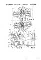
- FIG. 1illustrates a fluid delivery system incorporating a metering unit forming one embodiment of the present invention
- FIG. 2illustrates an inside view of one half of a cassette used in the metering unit
- FIG. 3illustrates a vertical cross-sectional view of the half taken along line 3--3 in FIG. 2 in the direction of the arrows;
- FIG. 4is an end view of the half taken along line 4--4 in FIG. 2 in the direction of the arrows;
- FIG. 5is a front view of a metering unit forming the first embodiment of the present invention.
- FIG. 6is a front view of a metering unit forming a second embodiment of the present invention.
- FIG. 7is a side view of the metering unit forming the second embodiment of the present invention.
- FIG. 8illustrates a fluid delivery system incorporating a metering unit forming a third embodiment of the present invention
- FIG. 9illustrates a vertical cross-sectional view of the cassette used in the third embodiment
- FIG. 10is an inside view of the one half of the cassette used in the third embodiment.
- FIG. 11is a vertical cross section of one half of the cassette taken along line 11--11 in FIG. 10 in the direction of the arrows;
- FIG. 12is a vertical cross section view of one half of the cassette taken along line 12--12 in the direction of the arrows in FIG. 10;
- FIG. 13is a vertical cross section view of one half of the cassette taken along line 13--13 in the direction of the arrows in FIG. 10;
- FIG. 14is a top view of the diaphragm employed with the cassette in the third embodiment.
- FIG. 15is a perspective view of an actuating mechanism for the cassette in the third embodiment
- FIG. 16is a bottom view of the actuating mechanism for the cassette of the third embodiment.
- FIG. 17is a side view of the frame in the actuating mechanism in partial cross section
- FIG. 18is a side view of one clamshell portion of the actuating mechanism
- FIG. 19is an end view of the actuating mechanism
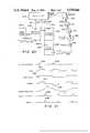
- FIG. 20is a block diagram of an electronic control circuit employed with the actuating mechanism.
- FIG. 21illustrates the relative time relationships of signals within the electronic control circuit.
- metering unit 10which is illustrated in FIGS. 1-5 and described hereinafter.
- the metering unit 10provides for a volumetrically controlled introduction of fluid from a container to a patient in the intravenous additive system 12 shown in FIG. 1.
- a container 14is suspended from a rod 16 as shown.
- the fluid 18 to be infusedis stored within the container 14.
- a delivery line 20extends from the container 14 to the patient 22.
- the metering unit 10is positioned within the delivery line 20.
- the fluid 18 and container 14are positioned above the metering unit 10 and patient 22 to provide a fluid pressure head to permit the metering unit 10 to function properly and infuse fluid into the patient.
- the metering unit 10can be positioned above fluid 18 and container 14 provided that the patient is still below container 14 with continuous fluid flow between the container and unit 10.
- the metering unit 10includes a frame 24 mounted in structure 25 and a cassette 26 positioned therein as best shown in FIG. 5. Also provided are electronics or other apparatus to operate the unit in the manner described hereafter.
- the cassette 26comprises two halves 28 and 30.
- the cassette 26has the significant advantage over prior known designs in performing the function noted hereafter while comprising only two halves 28 and 30.
- the halves 28 and 30are readily adapted for inexpensive, quantity production.
- Half 28is illustrated in FIGS. 2-4 and will be described hereinafter. In the preferred construction, the halves 28 and 30 are identical to reduce manufacturing costs. It will be understood that the description of half 28 will be equally applicable to half 30.
- the half 28includes an inner face 32 forming one side thereof. An outer face 34 is formed on the opposite side.
- a concave reservoir portion 36is formed within the inner face 32 as shown in FIGS. 2 and 3.
- An entry channel 38is also formed in the inner face 32 which extends from the reservoir portion 36 to an entry orifice 40 as shown in FIGS. 2 and 3.
- An exit channel 42is similarly formed within the inner face 32 which extends from the reservoir portion 36 to an exit orifice 44. Both channels 38 and 42 are offset from the elongate centerline of the half 28. In the preferred construction, the cross-sectional area of the entry and exit channels opening through the inner face 32 is minimized.
- An entry port portion 46is formed in inner face 32 at the end of the half 28 near entry orifice 40.
- the entry port portion 46has one end opening through a seal surface 48 surrounding the entry orifice 40 and formed in the outer face 34.
- a similar exit port portion 50is formed in the inner face 32 of the half 28 near the exit orifice 44.
- One end of the exit port portionextends through a seal surface 52 surrounding the orifice 44 and formed in the outer face 34.
- Annular notches 54 and 56are formed in the outer face 34 and are concentric with the entry and exit orifices 40 and 44, respectively.
- the halves 28 and 30are molded of a suitable plastic. The configuration of the inner and outer surfaces of the halves do not require the use of movable insert pins in the molding operation. This represents a significant cost advantage.
- An entry valve 58 formed of an elastomeric materialis provided with a lip 60 for sealing engagement within the annular groove 54.
- the entry valve 58includes a hemispherical sealing face 62 which may be moved into sealing engagement with the seal surface 48.
- An exit valve 64is provided with lips 66 for sealing engagement in the annular groove 56.
- the exit valve 64includes a hemispherical sealing face 68 for sealing engagement with the seal surface 52.
- the inner faces of the two halves 28 and 30are designed to be secured in a facing relation and separated by a flexible diaphragm 70. Suitable pins 72 and apertures 74 are provided on both halves 28 and 30 to properly align the halves in the facing relation.
- the halvesmay be maintained in this relation by any common means, such as glue, ultrasonic bonding, threaded screws, rivets, bolts, or even injection molded together, etc.
- the concave reservoir portionscombine to form a concave reservoir 76 separated into a first compartment 78 and a second compartment 80 by the flexible diaphragm 70.
- the flexible diaphragm 70also prevents fluid flow between the channels 38 and 42 within either half.
- the entry port portions 46 of each halfcombined to form an entry port 82.
- the exit port portions 50 of the two halvescombine to form an exit port 84.
- frame 24is movable relative to the cassette 26 about an axis X--X centered through the reservoir 76 in the cassette.
- the range of motionextends to angles ⁇ 1 and ⁇ 2 on either side of zero deflection.
- Frame 24is shown in FIG. 5 pivoted to angle ⁇ 1 .
- Members 91are positioned at the four corners of the frame 24 for guiding and supporting rods 93.
- the rods 93are urged toward the cassette by springs 95 acting between the members 91 and collars 97 on each of the rods.
- the tip of each of the rodslies adjacent a valve in cassette 26.
- the springs 95urge the rods 93 into engagement with the associated valves to close the valves and prevent fluid flow through the cassette.
- the metering unitmay be activated if the frame 24 is pivoted clockwise or the cassette 26 counterclockwise to the ⁇ 2 position. It will be seen that the rods acting on exit valve 64 and entry valve 86 will be withdrawn to permit the valves to move to the open position. The entry valve 58 and exit valve 88 are retained in the closed position. The metering unit may again be activated by moving frame 24 to the ⁇ 1 position as shown in FIG. 5, opening valves 58 and 88 and closing valves 64 and 86.
- Activation of the metering unit to open and close the alternate pairs of valveswill permit the metering of the predetermined volume of fluid into the exit port 84 for infusion into the patient upon each activation thereof.
- the rods 93 and springs 95can be designed to prevent the valves 58, 64, 86 and 88 from being open simultaneously in any position, even when the frame 24 is centered between the ⁇ 1 and ⁇ 2 positions.
- FIGS. 6 and 7A first modification of the present invention is illustrated in FIGS. 6 and 7 and comprises a metering unit 140.
- the metering unitincludes the cassette 26 described with reference to the first embodiment above.
- gear racks 94 and 96are slidably supported by the frame 24' for motion perpendicular to the elongate direction of the cassette.
- Each of the gear racksincludes extensions 98 and 100 for cooperation with the extensions 102 on the rods 90.
- the gear racks 94 and 96include gear teeth 104 and 106 for engaging the teeth of a gear 108 mounted for rotation about an axis Y-Y relative to the cassette.
- the operation of the metering units 10 and 140is described hereinafter.
- the portion of delivery line 20 extending from the fluid container 14is secured at the entry port 82.
- the portion of delivery line 20 extending to the patientis secured to the exit port 84. Without pivotal motion of frame 24 or rotation of gear 108, the valves in the cassette 26 are all retained in the closed position, preventing fluid flow from the container to the patient.
- the entry valve 86 and exit valve 64will be open. This will permit fluid to flow from the container at the higher pressure head through the entry port 82 and into the second compartment 80.
- the fluidflows into the second compartment 80, it deflects the flexible diaphragm 70 toward the inner surface of the reservoir portion 36 of half 28 until the second compartment has a volume substantially equal to the entire reservoir 76 and the first compartment 78 has substantially zero volume.
- the fluidwould be at a lower pressure head than the fluid in the second compartment 80 with the entry valve 58 in the closed position. The fluid entering the second compartment would urge the fluid in the first compartment through the open exit valve 64 and to the exit port 84 for infusion into the patient.
- the entry valve 58 and exit valve 88are opened. Simultaneously, the exit valve 64 and entry valve 86 are again moved to the closed position. Fluid from the container 14 then flows through the entry port 82 and into the first chamber 78. The relatively higher pressure head of the fluid entering the first compartment urges the flexible diaphragm 70 toward the inner surface of the reservoir portion of half 30, forcing the fluid in the second compartment past the exit valve 88 and into the exit port 84 for infusion into the patient.
- the volume of the reservoir 76is approximately 0.1 cc for adults, and 0.05 cc for pediatric applications. Therefore, upon each activation of the metering units 10 and 140 with a 0.1/cc reservoir, 0.1 cc of fluid is delivered for infusion into the patient. A predetermined rate of fluid may then readily be infused by the metering units 10 and 140 by activating the units at a predetermined frequency. If a steady flow is desired, a small reservoir volume and large cycle rate can be used to reduce the time delay between fluid delivery. The volume of fluid delivered for infusion into the patient may also readily be ascertained by summing the number of activations of the metering units 10 and 140.
- the metering units 10 and 140 of the present inventionform a significant improvement over the prior art. Neither unit relies upon pinch control to control the flow rate. Therefore, the inaccuracies associated with this technique can be eliminated. No drip chamber need be employed, eliminating the potential inaccuracy caused by the variation in drop volume.
- the cassette 26is formed of two equal halves which permits a much simpler construction than found in the prior art. While the halves 28 and 30 are identical in the preferred construction, they may be of any shape suitable to perform their function.
- the reservoir portion 36can be of spherical shape, for example. The reservoir portions on each half need not be equally shaped. The only restriction to reservoir shape is the necessity of the diaphragm 70 to be capable of urging a predetermined volume of fluid from each compartment.
- the delivery of fluidis also relatively independent of pressure head.
- the pressure head at the entry portneed only be sufficient to deflect the diaphragm.
- the cassette itselfmay be moved to meter fluid therethrough.
- the prior art deviceshave not been capable of this type of motion.
- the provision of a single entry and exit portsimplifies the connection of the metering unit in an additive system. This will prevent manipulation error and reduce the time required to prepare an additive system for operation.
- the provision of spring loaded rods, or other meanspermit the valves to be maintained in the closed position when the metering unit is not activated. This prevents infusion of fluid when the metering unit is not activated. If desired, the valves can be opened with free flow of fluid through the cassette controlled by a conventional pinch control or similar device on delivery line 20.
- the provision of a reservoir having a relatively small fluid volumepermits the metering units to achieve a relatively steady flow of fluid for infusion as the delivery of a number of small volumes on a discrete basis permits a relatively steady average flow rate to be established.
- the third embodiment of the present inventionis formed by metering unit 200 which is illustrated in FIGS. 8-21 and described hereinafter.
- the metering unit 200also provides for volumetrically controlled introduction of fluid from a container 14 to the patient 22.
- the metering unit 200includes a control section 202, an actuating frame 204 and a cassette 206.
- the cassette 206comprises two halves 208 and 210. In the preferred construction, the halves 208 and 210 are identical to reduce manufacturing cost. The detailed discussion of cassette half 208 hereinafter applies to half 210 as well.
- the half 208includes an inner face 212 forming one side thereof as best seen in FIG. 10.
- the inner face 212is formed predominantly in two offset parallel planes 286 and 292.
- An outer face 214is formed on the opposite side as best shown in FIGS. 9 and 11.
- a concave reservoir portion 216is formed within the inner face 212 as best seen in FIGS. 10 and 11.
- Dual parallel first channels 218are also formed in the inner face 212 which extend from a first orifice 220 to the reservoir portion 216.
- Dual parallel second channels 222are similarly formed within the inner face 212 which extend from the reservoir portion 216 to a second orifice 224.
- the first channels 218 and second channels 222extend into the surface 226 of the reservoir portion 216.
- the channels 218 and 222are connected by circular channels 228 and 230 also formed in surface 226.
- a cylindrical stem 232extends from one end of the cassette half 208 which includes a port 234.
- the cylindrical stem 232includes lugs 236 to secure a male Luer Lock fitting.
- a tubecan be solvent bonded within stem 232 or slip fit over the exterior of stem 232.
- the cassette halves 208 and 210are injection molded with a core pin to facilitate the formation of the multi-planar inner surface 212.
- the end of half 208 opposite stem 232is formed with a recess 238. The recess 238 is adapted to receive the stem on the half 210 when the halves form the cassette 206.
- the outer face 214 of half 208is formed with two concave seal surfaces 240 and 242 concentric with orifices 220 and 224.
- a first passage 244extends through the cassette half 208 opening through seal surface 240 a distance from orifice 220. The passage also opens into the port 234 through stem 232 and through the inner face 212 of the cassette half 208.
- a similar, second passage 246opens through the seal surface 242 and through the inner face 212.
- Annular notches 248 and 250are formed in the outer face 214 concentric with the seal surfaces 240 and 242, respectively.
- Outwardly extending ridges 252 and 254are provided with annular outwardly facing surfaces 256 and 258.
- An entry valve 260 and exit valve 262are provided with lips 264 for sealing engagement within the annular notches 248 and 250, respectively, as best seen in FIG. 9.
- Each valve 260 and 262includes a convex sealing face 266. Face 266 of valve 260 is movable into sealing engagement with the seal surface 240 to prevent flow between the first passage 244 and first orifice 220. Face 266 of valve 262 is movable into sealing engagement with seal surface 242 to prevent flow from second passage 246 to second orifice 224.
- the valves 260 and 262include lips 268 on their opposite side.
- Caps 270are provided with annular notches 272 for receiving the lips 268 as seen in FIG. 9.
- Each cap 270is provided with a circular ridge 274 for ultrasonic welding between the cap and cassette half which are formed of a plastic.
- the capsare placed on the cassette half with the valves secured therebetween as shown in FIG. 9.
- the piecesare then subjected to vibration at a high frequency, approximately 20 kilohertz.
- the mechanical energy of vibrationis directed between the cap and cassette half through the ridge 274.
- the adjacent areasbecome liquid from the frictional heat generation.
- the cap and cassette halfare clamped together until the pieces cool, resulting in a secure and fluid tight weld between the cap and cassette half.
- the capstherefore retain the valves 260 and 262 in close proximity to the cassette half and the valves may be actuated by mechanical action through the aperture 276 in each cap.
- the cassette half 208is formed with alignment pins 278 extending from the inner face 212 on opposite sides of the face.
- Two alignment holes 280, sized to receive the pins 278,are formed in the inner face on opposite sides of the cassette half.
- the inner face 212is generally formed in two parallel planes 286 and 292.
- Curvilinear ridges 282 with planar surfaces 284extend from plane 292 to plane 286.
- the surface 288 through which the orifices, passages, channels and reservoir portion are formedlies in plane 286.
- Surface 290 on either side of surfaces 288 and within the ridges 282is formed in plane 292.
- the pins 278extend from and holes 280 are formed in the surface 290.
- Curvilinear energy directors 294extend outwardly from the planar surfaces 284 and the plane 286 on the curvilinear ridges 282.
- the inner faces of the two halves 208 and 210are designed to be secured in a facing relation and separated by a flexible diaphragm 296.
- the diaphragm 296is best illustrated in FIG. 14.
- the diaphragmhas a generally curvilinear shape with holes 298 for passage of the alignment pins 278.
- Two holes 300permit free communication between the passages 244 and 246 of the two cassette halves.
- Port 234 and passage 244 of half 208 and passage 246 of half 210are each sections of an entry port for inflow of fluid.
- Port 234 and passage 244 of half 210 and passage 246 of half 208are each sections of an exit port for outflow of fluid.
- the halvesare then ultrasonically welded between the surfaces 284 through energy directors 294.
- the cassette halvescan also be formed of material other than plastics.
- the cassette halvescan also be secured together by any common means, such as glue, threaded screws, rivets, bolts, or even injection molded together, etc. as best suited for the material used.
- the cassette 206When the cassette halves 208 and 210 are in the facing relation with the diaphragm 296 therebetween, the cassette 206 is formed as best seen in FIG. 9.
- the concave reservoir portions 216combine to form a concave reservoir 302.
- the reservoir 302is separated into a first compartment 304 and a second compartment 306 by diaphragm 296. With the cassette halves secured together, the diaphragm 296 forms an effective seal between the passages, orifices, channels, reservoir portions and remainder of the cassette halves on the surface 288.
- valves illustratedare designed to be open in the absence of an external influence. However, the valves can as readily be closed if desired in the absence of an external influence. When the valves are deflected inward toward the inner face of the half cassette to which they are secured, the valve will close and prevent fluid flow between the associated passage and orifice.
- the cassette halves 208 and 210are preferably constructed with integral finger grip extensions 312 to ease handling of the cassette.
- the operation of the cassette 206is substantially identical to the operation of cassettes 10 and 140 described hereinabove.
- the use of dual parallel channels 218 and 222reduces the variance of fluid delivery with head pressure of the fluid within the cassette. If a single channel is employed, and particularly if the channels in the cassette halves are on directly opposite sides of the diaphragm, the pressure in the fluid within the cassette tends to deflect the diaphragm into the channel having the lower pressure fluid. This can result in an increase in the fluid delivered above the quantity determined by the reservoir, with the increase being dependent upon the head pressure of the fluid delivered.
- the use of multiple passages 244 and 246minimizes this problem by reducing the unsupported surface area of the diaphragm 296.
- the extension of the channels 218, 222 and circular channels 228 and 230 in surface 226reduces the potential for entrapment of fluid against the surfaces 226 as the diaphragm deflects sufficiently to approach the surfaces 226. Without these channels, ripples can develop in the diaphragm which may retain quantities of fluid within the reservoir portions and result in a delivery of less fluid than desired.
- the cassette 206can be mounted in and actuated by the actuating assembly 204 best illustrated in FIGS. 15-20.
- the actuating assembly 204includes a frame 314 firmly secured to the metering unit 200.
- Spring loaded clamshell clamps 316are pivoted at one of their ends by pins 318 to one end of frame 314.
- the front of the clamps 316include hook portions 320 which spread apart when the cassette 206 is inserted between the bars and snap together to retain the cassette within the frame as shown in FIGS. 15-19.
- the barsare urged together to retain the cassette within the frame by clamshell clamp retention springs 322 passing through apertures 323 in the frame 314.
- actuating arms 324two on each of the clamps 316, are pivoted at their center to pins 319.
- the forward end of each armis adapted for contacting one of the four valves employed in cassette 206.
- a button closure pad 321is threadedly received in each arm 324 for actual contact with the valves.
- the pads 321can be screwed in and out of the arms to provide adjustments.
- the pivoting of the forward end of an arminward closes the associated valve when the cassette 206 is clamped by clamps 316.
- Arm tension springs 325are positioned through apertures 327 in the frame 314. The springs 325 act on the arms between their pivot axis and valve contacting end to urge the arms away from the valves of the cassette 206.
- the end of each arm opposite the valve contacting endhas a cam follower 329 mounted thereon.
- a motor 326is mounted on the frame 314 for rotating a drive shaft 328 centrally located within the frame 314 at one end.
- the drive shaft 328mounts cams 330 and 332 and a position disk 334.
- An optical interrupter assembly 336is mounted to sense the passage of portions of the position disk to sense the rotational position of the drive shaft 328.
- the cams 330 and 332are designed to pivot the actuating arms 324 to alternately open and close each valve on the sides of the cassette.
- the cams 330 and 332are designed so that only one of the two valves controlled by a given cam can be in the open position at a given time. This can be accomplished by having a single raised camming surface on each of the cams 330 and 332 which can allow only one of the arms controlled by each of the cams to be moved into engagement with the valve which it controls.
- the cams 330 and 332are designed to operate the valves in a three stage sequence. In the first stage, the cams 330 and 332 will initially be positioned to cause a first pair of valves to be open and a second pair to be closed. The cams will then close all the valves in the second stage. Finally, the cam will open the second pair of valves and close the first pair of valves in the third stage.
- This sequencehas several critical advantages. First, the sequence permits great accuracy in fluid delivery through the cassette. That is, upon each movement of the cams to open a pair of valves, a volume limited to the volume of the fluid chamber in the cassette will be delivered to the patient. Secondly, should any component in the metering unit fail with a stoppage of the drive shaft 328 in a given position, the maximum volume of fluid which could be delivered to the patient after the malfunction is again the volume of the chamber in the cassette.
- FIG. 20illustrates a block diagram of the control system.
- FIG. 21illustrates the time relationships of activity in the control system.
- An electronic clock circuit 402generates a clock pulse or cycle requests 404 at uniform time intervals.
- the frequency of the cycle requestsis determined by the desired fluid delivery rate.
- a cycle request 404is generated when it is desired to deliver a volume of fluid to the patient equivalent to the volume of the delivery chamber in the cassette.
- the cycle request 404is transferred to a set/reset bistable circuit 406 over line 408.
- the cycle requestenters the circuit 406 at the S terminal, thereby setting the circuit and causing the circuit 406 to generate a run signal 410 over line 412.
- a motor driver circuit 414receives the run signal 410 and applies power to the motor 326 to rotate the shaft 328 and cams 330 and 332.
- the circuit 414can cause rotation of shaft 328 in both directions.
- the power to rotate the shaft 328 in a first directionis represented by a position signal 417.
- the rotation in the opposite directionis represented by negative signal 419.
- the direction of rotation of motor 326is determined by the value of a direction signal 416 delivered over line 418 to the motor driver circuit 414 from a trigger bistable circuit 420.
- the motor 326moves the shaft between first position A and second position B. In first position A, one set of valves is open and one closed. In second position B, the other set of valves is open and the first set closed.
- Motor 326continues to run until the optical interrupter assembly 336 senses motion of the position disk 334 sufficient for the shaft 328 to move between positions A and B to alter the positions of all four valves in the cassette.
- the interrupter assembly 336then delivers a completion of motion signal 422 over line 424 to a pulse bistable circuit 426.
- the pulse bistable circuit 426then generates a reset signal 428 which travels over line 430 to the set/reset bistable circuit 406 to reset the circuit 406.
- the run signal 410is deactivated and the motor driver circuit 414 therefore prevents further motion in the drive motor 326.
- the trigger bistable circuit 420alternates between on and off values each time the set/reset bistable circuit 406 receives a cycle request 404. This causes the motor driver circuit 414 to alternately apply opposite polarity to the motor, causing the rotation of the motor, and hence the drive shaft 328 and cams 330 and 332 to be in opposite directions each time a cycle request 404 is generated. The shaft therefore alternates between position A and position B.
- the cassette 206can be removed from the actuating assembly 204 by rotating the spreader lever 432.
- the spreader lever 432rotates the spreader shaft 434.
- the camsurge the clamshell clamps 316 apart to permit removal of the cassette 206.
- a clamshell locking cam 440can be secured on the shaft 434 to lock the cassette 206 within the actuating assembly 204 by preventing motion of the clamshell clamps 316.
- a clamshell locking shaft and clevis assembly 442can be used to remotely lock the cassette within the actuating assembly.
- the delivery line 20 extending from the fluid containeris secured, for example, at the port 234 of the cassette half 208.
- the delivery line 20extends from the exit port 234 in the second cassette half 210 for delivery to the patient.
- the motor 326can be activated to move cams 330 and 332 to position A so that the entry valve 260 and exit valve 310 are opened.
- the exit valve 262 and entry valve 308are closed in position A. This will permit fluid to flow from the container at a higher pressure head through the port 234, first passage 244, first orifice 220 and into the channels 218 of half 208 for entry into the first compartment 304.
- the diaphragm 296deflects into the second compartment 306, driving any fluid within the second compartment through the first channels 218, through the first passage 244 and out the port 234 of the cassette half 210 for delivery to the patient.
- the motor 326is then activated to move cams 330 and 332 to close all the valves intermediate positions A and B. As the motor 326 continues to move to position B, cams 330 and 332 close entry valve 260 and exit valve 310 and open exit valve 262 and entry valve 308. This permits fluid to flow from the port 234 and first passage 244 of cassette half 208 into the second passage 246 of the cassette halve 210 through a hole 300. The flow continues through the second channels 222 of cassette half 210. The fluid then flows into the second compartment 306, deflecting the diaphragm 296 in the opposite direction to fill the volume of the reservoir 302.
- the fluid in the first compartment 304is driven from the reservoir 302 through the second channels 222 in cassette half 208 through the second orifice 224 in cassette half 208, through the passages 246 and 244 in the cassette halves 208 and 210, respectively, to the port 234 in the second cassette half 210 for delivery to the patient.
- the limits of motion of shaft 328are 180° apart.
- the surface of cams 330 and 332are designed so that each set of valves is open for about 80° of travel from one limit with the 20° in mid-motion with all valves closed. Thus, each time the valve positions are changed, there is a guaranteed period when all valves are closed. The device prevents all valves from being open simultaneously, even in the event of a failure of the electronic circuits.
- the cassette 206 with actuating assembly 204can be operated in a manner identical to metering units 10 and 140 to achieve similar advantages.
- the valves describedcan be substituted for by any functional equivalent, for example rotary valves.
- the valves of metering units 10, 140 and 200can be provided with magnetic material for actuation by a magnetic source, such as an electromagnet. Pneumatic operation of the valves is also possible to effect opening and closing of the valves.
- the preferred material of construction of the diaphragms and valves employed in the metering units described hereinaboveis silicon. This material provides a good shelf life, relative insensitivity to temperature and good mechanical flexibility. However, latex rubber, urethane or a Krayton material or other suitable material can be used.
- the control system 400 of metering unit 200is employed to operate the metering unit to deliver a desired flow rate entered into the delivery controls 370 by the operator.
- the control system 400can also provide alarms to alert the operator to any condition desired.
- a display 372can be incorporated to represent the delivery system, in particular a representation of a system employing a primary and secondary fluid. With a primary and secondary fluid the display can illustrate the particular source delivering fluid at a given moment.
- the displaycan also provide an instantaneous read out of the volume of fluid infused to the patient and the remaining volume to be infused.
Landscapes
- Health & Medical Sciences (AREA)
- Heart & Thoracic Surgery (AREA)
- Animal Behavior & Ethology (AREA)
- Fluid Mechanics (AREA)
- Vascular Medicine (AREA)
- Engineering & Computer Science (AREA)
- Anesthesiology (AREA)
- Biomedical Technology (AREA)
- Physics & Mathematics (AREA)
- General Physics & Mathematics (AREA)
- Hematology (AREA)
- Life Sciences & Earth Sciences (AREA)
- General Health & Medical Sciences (AREA)
- Public Health (AREA)
- Veterinary Medicine (AREA)
- Infusion, Injection, And Reservoir Apparatuses (AREA)
- Control Of Multiple Motors (AREA)
- Control Of Stepping Motors (AREA)
- Portable Nailing Machines And Staplers (AREA)
Abstract
Description
Claims (38)
Priority Applications (4)
| Application Number | Priority Date | Filing Date | Title |
|---|---|---|---|
| US06/404,811US4559044A (en) | 1982-08-03 | 1982-08-03 | Volumetric metering unit for intravenous fluid addition |
| GB08320165AGB2125009B (en) | 1982-08-03 | 1983-07-26 | Volumetric metering unit for intravenous fluid addition |
| DE19833327494DE3327494A1 (en) | 1982-08-03 | 1983-07-29 | DEVICE FOR DOSING A FLOWING LIQUID |
| JP58141272AJPS5981518A (en) | 1982-08-03 | 1983-08-03 | Weigher and its driving method and drive |
Applications Claiming Priority (1)
| Application Number | Priority Date | Filing Date | Title |
|---|---|---|---|
| US06/404,811US4559044A (en) | 1982-08-03 | 1982-08-03 | Volumetric metering unit for intravenous fluid addition |
Publications (1)
| Publication Number | Publication Date |
|---|---|
| US4559044Atrue US4559044A (en) | 1985-12-17 |
Family
ID=23601147
Family Applications (1)
| Application Number | Title | Priority Date | Filing Date |
|---|---|---|---|
| US06/404,811Expired - Fee RelatedUS4559044A (en) | 1982-08-03 | 1982-08-03 | Volumetric metering unit for intravenous fluid addition |
Country Status (4)
| Country | Link |
|---|---|
| US (1) | US4559044A (en) |
| JP (1) | JPS5981518A (en) |
| DE (1) | DE3327494A1 (en) |
| GB (1) | GB2125009B (en) |
Cited By (61)
| Publication number | Priority date | Publication date | Assignee | Title |
|---|---|---|---|---|
| US5088515A (en)* | 1989-05-01 | 1992-02-18 | Kamen Dean L | Valve system with removable fluid interface |
| US5370612A (en)* | 1992-04-03 | 1994-12-06 | Sharp Kabushiki Kaisha | Infusion apparatus capable of measuring a fluid delivery rate taking a dead band into account |
| US5431627A (en)* | 1993-11-12 | 1995-07-11 | Abbott Laboratories | Cassette identification system for use with a multi-program drug infusion pump |
| US5531698A (en)* | 1994-04-15 | 1996-07-02 | Sims Deltec, Inc. | Optical reflection systems and methods for cassette identification fordrug pumps |
| US5853386A (en)* | 1996-07-25 | 1998-12-29 | Alaris Medical Systems, Inc. | Infusion device with disposable elements |
| US5935099A (en)* | 1992-09-09 | 1999-08-10 | Sims Deltec, Inc. | Drug pump systems and methods |
| USRE38189E1 (en) | 1995-07-12 | 2003-07-15 | Docusys, Inc. | Medication delivery and monitoring system and methods |
| US20030220608A1 (en)* | 2002-05-24 | 2003-11-27 | Bruce Huitt | Method and apparatus for controlling medical fluid pressure |
| US20030217957A1 (en)* | 2002-05-24 | 2003-11-27 | Bowman Joseph H. | Heat seal interface for a disposable medical fluid unit |
| US20030220605A1 (en)* | 2002-05-24 | 2003-11-27 | Bowman Joseph H. | Disposable medical fluid unit having rigid frame |
| US6679865B2 (en) | 2001-12-07 | 2004-01-20 | Nedrip Ltd. | Fluid flow meter for gravity fed intravenous fluid delivery systems |
| US6685678B2 (en) | 2000-03-22 | 2004-02-03 | Docusys, Inc. | Drug delivery and monitoring system |
| US6764761B2 (en) | 2002-05-24 | 2004-07-20 | Baxter International Inc. | Membrane material for automated dialysis system |
| US20040194196A1 (en)* | 2003-04-02 | 2004-10-07 | Muderlak Kenneth J. | Apparatus and method for automatically cleaning a tank-style toilet |
| US7153286B2 (en) | 2002-05-24 | 2006-12-26 | Baxter International Inc. | Automated dialysis system |
| US7347836B2 (en) | 1992-09-09 | 2008-03-25 | Smiths Medical, Inc. | Drug pump systems and methods |
| US8070709B2 (en) | 2003-10-28 | 2011-12-06 | Baxter International Inc. | Peritoneal dialysis machine |
| US8133197B2 (en) | 2008-05-02 | 2012-03-13 | Smiths Medical Asd, Inc. | Display for pump |
| US8149131B2 (en) | 2006-08-03 | 2012-04-03 | Smiths Medical Asd, Inc. | Interface for medical infusion pump |
| US8172789B2 (en) | 2000-02-10 | 2012-05-08 | Baxter International Inc. | Peritoneal dialysis system having cassette-based-pressure-controlled pumping |
| US8206338B2 (en) | 2002-12-31 | 2012-06-26 | Baxter International Inc. | Pumping systems for cassette-based dialysis |
| US8250483B2 (en) | 2002-02-28 | 2012-08-21 | Smiths Medical Asd, Inc. | Programmable medical infusion pump displaying a banner |
| US8435206B2 (en) | 2006-08-03 | 2013-05-07 | Smiths Medical Asd, Inc. | Interface for medical infusion pump |
| US8504179B2 (en) | 2002-02-28 | 2013-08-06 | Smiths Medical Asd, Inc. | Programmable medical infusion pump |
| CN103373484A (en)* | 2012-04-20 | 2013-10-30 | 比尔克特韦尔克有限公司 | Pneumatic dosing unit and pneumatic dosing system |
| US8858526B2 (en) | 2006-08-03 | 2014-10-14 | Smiths Medical Asd, Inc. | Interface for medical infusion pump |
| WO2014193246A1 (en)* | 2013-05-31 | 2014-12-04 | Adept Limited | Fluid metering apparatus and system |
| US8954336B2 (en) | 2004-02-23 | 2015-02-10 | Smiths Medical Asd, Inc. | Server for medical device |
| US8965707B2 (en) | 2006-08-03 | 2015-02-24 | Smiths Medical Asd, Inc. | Interface for medical infusion pump |
| CN104436359A (en)* | 2014-12-27 | 2015-03-25 | 贵州师范大学 | Infusion set capable of stopping automatically |
| US8992462B2 (en) | 2002-07-19 | 2015-03-31 | Baxter International Inc. | Systems and methods for performing peritoneal dialysis |
| DE102013111799A1 (en)* | 2013-10-25 | 2015-04-30 | Dominik Niedenzu | Precision metering device for conveying a fluid |
| DE102013111800A1 (en)* | 2013-10-25 | 2015-04-30 | Dominik Niedenzu | Precision metering device with expandable volume chamber |
| US9134735B2 (en) | 2011-09-30 | 2015-09-15 | Hospira, Inc. | Intravenous flow rate controller |
| US9514283B2 (en) | 2008-07-09 | 2016-12-06 | Baxter International Inc. | Dialysis system having inventory management including online dextrose mixing |
| US9582645B2 (en) | 2008-07-09 | 2017-02-28 | Baxter International Inc. | Networked dialysis system |
| US9675745B2 (en) | 2003-11-05 | 2017-06-13 | Baxter International Inc. | Dialysis systems including therapy prescription entries |
| US10022498B2 (en) | 2011-12-16 | 2018-07-17 | Icu Medical, Inc. | System for monitoring and delivering medication to a patient and method of using the same to minimize the risks associated with automated therapy |
| US10166328B2 (en) | 2013-05-29 | 2019-01-01 | Icu Medical, Inc. | Infusion system which utilizes one or more sensors and additional information to make an air determination regarding the infusion system |
| US10342917B2 (en) | 2014-02-28 | 2019-07-09 | Icu Medical, Inc. | Infusion system and method which utilizes dual wavelength optical air-in-line detection |
| US10430761B2 (en) | 2011-08-19 | 2019-10-01 | Icu Medical, Inc. | Systems and methods for a graphical interface including a graphical representation of medical data |
| US10463788B2 (en) | 2012-07-31 | 2019-11-05 | Icu Medical, Inc. | Patient care system for critical medications |
| US10578098B2 (en) | 2005-07-13 | 2020-03-03 | Baxter International Inc. | Medical fluid delivery device actuated via motive fluid |
| US10578474B2 (en) | 2012-03-30 | 2020-03-03 | Icu Medical, Inc. | Air detection system and method for detecting air in a pump of an infusion system |
| US10596316B2 (en) | 2013-05-29 | 2020-03-24 | Icu Medical, Inc. | Infusion system and method of use which prevents over-saturation of an analog-to-digital converter |
| US10635784B2 (en) | 2007-12-18 | 2020-04-28 | Icu Medical, Inc. | User interface improvements for medical devices |
| US10656894B2 (en) | 2017-12-27 | 2020-05-19 | Icu Medical, Inc. | Synchronized display of screen content on networked devices |
| US10682460B2 (en) | 2013-01-28 | 2020-06-16 | Smiths Medical Asd, Inc. | Medication safety devices and methods |
| US10850024B2 (en) | 2015-03-02 | 2020-12-01 | Icu Medical, Inc. | Infusion system, device, and method having advanced infusion features |
| US10874793B2 (en) | 2013-05-24 | 2020-12-29 | Icu Medical, Inc. | Multi-sensor infusion system for detecting air or an occlusion in the infusion system |
| US11135360B1 (en) | 2020-12-07 | 2021-10-05 | Icu Medical, Inc. | Concurrent infusion with common line auto flush |
| US11179516B2 (en) | 2017-06-22 | 2021-11-23 | Baxter International Inc. | Systems and methods for incorporating patient pressure into medical fluid delivery |
| US11246985B2 (en) | 2016-05-13 | 2022-02-15 | Icu Medical, Inc. | Infusion pump system and method with common line auto flush |
| US11278671B2 (en) | 2019-12-04 | 2022-03-22 | Icu Medical, Inc. | Infusion pump with safety sequence keypad |
| US11324888B2 (en) | 2016-06-10 | 2022-05-10 | Icu Medical, Inc. | Acoustic flow sensor for continuous medication flow measurements and feedback control of infusion |
| US11344668B2 (en) | 2014-12-19 | 2022-05-31 | Icu Medical, Inc. | Infusion system with concurrent TPN/insulin infusion |
| US11344673B2 (en) | 2014-05-29 | 2022-05-31 | Icu Medical, Inc. | Infusion system and pump with configurable closed loop delivery rate catch-up |
| US11478578B2 (en) | 2012-06-08 | 2022-10-25 | Fresenius Medical Care Holdings, Inc. | Medical fluid cassettes and related systems and methods |
| US11883361B2 (en) | 2020-07-21 | 2024-01-30 | Icu Medical, Inc. | Fluid transfer devices and methods of use |
| US12350233B2 (en) | 2021-12-10 | 2025-07-08 | Icu Medical, Inc. | Medical fluid compounding systems with coordinated flow control |
| USD1091564S1 (en) | 2021-10-13 | 2025-09-02 | Icu Medical, Inc. | Display screen or portion thereof with graphical user interface for a medical device |
Families Citing this family (1)
| Publication number | Priority date | Publication date | Assignee | Title |
|---|---|---|---|---|
| DE202009014944U1 (en)* | 2009-03-26 | 2010-10-21 | Helmholtz-Zentrum Für Umweltforschung Gmbh - Ufz | Dosing device for bioreactors |
Citations (5)
| Publication number | Priority date | Publication date | Assignee | Title |
|---|---|---|---|---|
| US3575161A (en)* | 1968-03-07 | 1971-04-20 | Seymour B London | Valve for biological systems |
| US4121584A (en)* | 1976-10-15 | 1978-10-24 | R. Scott Turner | Method and apparatus for controlling the dispensing of fluid |
| US4181245A (en)* | 1978-02-17 | 1980-01-01 | Baxter Travenol Laboratories, Inc. | Casette for use with an I.V. infusion controller |
| US4204538A (en)* | 1978-06-07 | 1980-05-27 | Imed Corporation | Cassette for intravenous controller |
| US4391598A (en)* | 1981-04-28 | 1983-07-05 | Quest Medical, Inc. | Intravenous drug additive delivery system with electronic control |
Family Cites Families (6)
| Publication number | Priority date | Publication date | Assignee | Title |
|---|---|---|---|---|
| GB1115231A (en)* | 1964-11-04 | 1968-05-29 | Christopher Ian Arthur Ellis | Improved dispensing device |
| US3804107A (en)* | 1972-04-05 | 1974-04-16 | G Lisitsina | Device for preparation of a dialyzing solution |
| JPS5119850B2 (en)* | 1972-07-13 | 1976-06-21 | ||
| JPS5028756B1 (en)* | 1974-08-15 | 1975-09-18 | ||
| ES478123A1 (en)* | 1979-02-27 | 1979-05-16 | Prats Riera Alberto | Apparatus for dispensing a controlled dose of a fluid |
| CA1166916A (en)* | 1979-09-04 | 1984-05-08 | Gordon E. Smith | Metering device for biological fluids |
- 1982
- 1982-08-03USUS06/404,811patent/US4559044A/ennot_activeExpired - Fee Related
- 1983
- 1983-07-26GBGB08320165Apatent/GB2125009B/ennot_activeExpired
- 1983-07-29DEDE19833327494patent/DE3327494A1/ennot_activeWithdrawn
- 1983-08-03JPJP58141272Apatent/JPS5981518A/enactivePending
Patent Citations (5)
| Publication number | Priority date | Publication date | Assignee | Title |
|---|---|---|---|---|
| US3575161A (en)* | 1968-03-07 | 1971-04-20 | Seymour B London | Valve for biological systems |
| US4121584A (en)* | 1976-10-15 | 1978-10-24 | R. Scott Turner | Method and apparatus for controlling the dispensing of fluid |
| US4181245A (en)* | 1978-02-17 | 1980-01-01 | Baxter Travenol Laboratories, Inc. | Casette for use with an I.V. infusion controller |
| US4204538A (en)* | 1978-06-07 | 1980-05-27 | Imed Corporation | Cassette for intravenous controller |
| US4391598A (en)* | 1981-04-28 | 1983-07-05 | Quest Medical, Inc. | Intravenous drug additive delivery system with electronic control |
Cited By (145)
| Publication number | Priority date | Publication date | Assignee | Title |
|---|---|---|---|---|
| US5088515A (en)* | 1989-05-01 | 1992-02-18 | Kamen Dean L | Valve system with removable fluid interface |
| US5370612A (en)* | 1992-04-03 | 1994-12-06 | Sharp Kabushiki Kaisha | Infusion apparatus capable of measuring a fluid delivery rate taking a dead band into account |
| US5935099A (en)* | 1992-09-09 | 1999-08-10 | Sims Deltec, Inc. | Drug pump systems and methods |
| US7347836B2 (en) | 1992-09-09 | 2008-03-25 | Smiths Medical, Inc. | Drug pump systems and methods |
| US7654976B2 (en) | 1992-09-09 | 2010-02-02 | Smiths Medical Asd, Inc. | Drug pump systems and methods |
| US5431627A (en)* | 1993-11-12 | 1995-07-11 | Abbott Laboratories | Cassette identification system for use with a multi-program drug infusion pump |
| US6123686A (en)* | 1994-04-15 | 2000-09-26 | Sims Deltec, Inc. | Systems and methods for cassette identification for drug pumps |
| US5647854A (en)* | 1994-04-15 | 1997-07-15 | Sims Deltec, Inc. | Base plate for a drug pump |
| US5531697A (en)* | 1994-04-15 | 1996-07-02 | Sims Deltec, Inc. | Systems and methods for cassette identification for drug pumps |
| US5531698A (en)* | 1994-04-15 | 1996-07-02 | Sims Deltec, Inc. | Optical reflection systems and methods for cassette identification fordrug pumps |
| USRE38189E1 (en) | 1995-07-12 | 2003-07-15 | Docusys, Inc. | Medication delivery and monitoring system and methods |
| US5853386A (en)* | 1996-07-25 | 1998-12-29 | Alaris Medical Systems, Inc. | Infusion device with disposable elements |
| US6110153A (en)* | 1996-07-25 | 2000-08-29 | Alaris Medical Systems, Inc. | Infusion device with optical sensor |
| US9474842B2 (en) | 2000-02-10 | 2016-10-25 | Baxter International Inc. | Method and apparatus for monitoring and controlling peritoneal dialysis therapy |
| US8323231B2 (en) | 2000-02-10 | 2012-12-04 | Baxter International, Inc. | Method and apparatus for monitoring and controlling peritoneal dialysis therapy |
| US8206339B2 (en) | 2000-02-10 | 2012-06-26 | Baxter International Inc. | System for monitoring and controlling peritoneal dialysis |
| US8172789B2 (en) | 2000-02-10 | 2012-05-08 | Baxter International Inc. | Peritoneal dialysis system having cassette-based-pressure-controlled pumping |
| US10322224B2 (en) | 2000-02-10 | 2019-06-18 | Baxter International Inc. | Apparatus and method for monitoring and controlling a peritoneal dialysis therapy |
| US6685678B2 (en) | 2000-03-22 | 2004-02-03 | Docusys, Inc. | Drug delivery and monitoring system |
| US20040082918A1 (en)* | 2000-03-22 | 2004-04-29 | Docusys, Inc. | Drug delivery and monitoring system |
| US20060144942A1 (en)* | 2000-03-22 | 2006-07-06 | Docusys, Inc. | Drug delivery and monitoring system |
| US7074209B2 (en) | 2000-03-22 | 2006-07-11 | Docusys, Inc. | Drug delivery and monitoring system |
| US7115113B2 (en) | 2000-03-22 | 2006-10-03 | Docusys, Inc. | Drug delivery and monitoring system |
| US6679865B2 (en) | 2001-12-07 | 2004-01-20 | Nedrip Ltd. | Fluid flow meter for gravity fed intravenous fluid delivery systems |
| US8250483B2 (en) | 2002-02-28 | 2012-08-21 | Smiths Medical Asd, Inc. | Programmable medical infusion pump displaying a banner |
| US8504179B2 (en) | 2002-02-28 | 2013-08-06 | Smiths Medical Asd, Inc. | Programmable medical infusion pump |
| US6939111B2 (en) | 2002-05-24 | 2005-09-06 | Baxter International Inc. | Method and apparatus for controlling medical fluid pressure |
| US20030220605A1 (en)* | 2002-05-24 | 2003-11-27 | Bowman Joseph H. | Disposable medical fluid unit having rigid frame |
| US7175606B2 (en) | 2002-05-24 | 2007-02-13 | Baxter International Inc. | Disposable medical fluid unit having rigid frame |
| US7087036B2 (en) | 2002-05-24 | 2006-08-08 | Baxter International Inc. | Fail safe system for operating medical fluid valves |
| US7500962B2 (en) | 2002-05-24 | 2009-03-10 | Baxter International Inc. | Medical fluid machine with air purging pump |
| US6953323B2 (en) | 2002-05-24 | 2005-10-11 | Baxter International Inc. | Medical fluid pump |
| US7789849B2 (en) | 2002-05-24 | 2010-09-07 | Baxter International Inc. | Automated dialysis pumping system using stepper motor |
| US7815595B2 (en) | 2002-05-24 | 2010-10-19 | Baxter International Inc. | Automated dialysis pumping system |
| US8066671B2 (en) | 2002-05-24 | 2011-11-29 | Baxter International Inc. | Automated dialysis system including a piston and stepper motor |
| US20030217957A1 (en)* | 2002-05-24 | 2003-11-27 | Bowman Joseph H. | Heat seal interface for a disposable medical fluid unit |
| US8075526B2 (en) | 2002-05-24 | 2011-12-13 | Baxter International Inc. | Automated dialysis system including a piston and vacuum source |
| US10137235B2 (en) | 2002-05-24 | 2018-11-27 | Baxter International Inc. | Automated peritoneal dialysis system using stepper motor |
| US9511180B2 (en) | 2002-05-24 | 2016-12-06 | Baxter International Inc. | Stepper motor driven peritoneal dialysis machine |
| US6814547B2 (en) | 2002-05-24 | 2004-11-09 | Baxter International Inc. | Medical fluid pump |
| US10751457B2 (en) | 2002-05-24 | 2020-08-25 | Baxter International Inc. | Systems with disposable pumping unit |
| US7153286B2 (en) | 2002-05-24 | 2006-12-26 | Baxter International Inc. | Automated dialysis system |
| US6764761B2 (en) | 2002-05-24 | 2004-07-20 | Baxter International Inc. | Membrane material for automated dialysis system |
| US20040010223A1 (en)* | 2002-05-24 | 2004-01-15 | Don Busby | Fail safe system for operating medical fluid valves |
| US8376999B2 (en) | 2002-05-24 | 2013-02-19 | Baxter International Inc. | Automated dialysis system including touch screen controlled mechanically and pneumatically actuated pumping |
| US8403880B2 (en) | 2002-05-24 | 2013-03-26 | Baxter International Inc. | Peritoneal dialysis machine with variable voltage input control scheme |
| US20030220608A1 (en)* | 2002-05-24 | 2003-11-27 | Bruce Huitt | Method and apparatus for controlling medical fluid pressure |
| US9504778B2 (en) | 2002-05-24 | 2016-11-29 | Baxter International Inc. | Dialysis machine with electrical insulation for variable voltage input |
| US8506522B2 (en) | 2002-05-24 | 2013-08-13 | Baxter International Inc. | Peritoneal dialysis machine touch screen user interface |
| US8529496B2 (en) | 2002-05-24 | 2013-09-10 | Baxter International Inc. | Peritoneal dialysis machine touch screen user interface |
| US9675744B2 (en) | 2002-05-24 | 2017-06-13 | Baxter International Inc. | Method of operating a disposable pumping unit |
| US9744283B2 (en) | 2002-05-24 | 2017-08-29 | Baxter International Inc. | Automated dialysis system using piston and negative pressure |
| US8684971B2 (en) | 2002-05-24 | 2014-04-01 | Baxter International Inc. | Automated dialysis system using piston and negative pressure |
| US9775939B2 (en) | 2002-05-24 | 2017-10-03 | Baxter International Inc. | Peritoneal dialysis systems and methods having graphical user interface |
| US9795729B2 (en) | 2002-07-19 | 2017-10-24 | Baxter International Inc. | Pumping systems for cassette-based dialysis |
| US10525184B2 (en) | 2002-07-19 | 2020-01-07 | Baxter International Inc. | Dialysis system and method for pumping and valving according to flow schedule |
| US9283312B2 (en) | 2002-07-19 | 2016-03-15 | Baxter International Inc. | Dialysis system and method for cassette-based pumping and valving |
| US8679054B2 (en) | 2002-07-19 | 2014-03-25 | Baxter International Inc. | Pumping systems for cassette-based dialysis |
| US8992462B2 (en) | 2002-07-19 | 2015-03-31 | Baxter International Inc. | Systems and methods for performing peritoneal dialysis |
| US8740837B2 (en) | 2002-07-19 | 2014-06-03 | Baxter International Inc. | Pumping systems for cassette-based dialysis |
| US8740836B2 (en) | 2002-07-19 | 2014-06-03 | Baxter International Inc. | Pumping systems for cassette-based dialysis |
| US11020519B2 (en) | 2002-07-19 | 2021-06-01 | Baxter International Inc. | Systems and methods for performing peritoneal dialysis |
| US8206338B2 (en) | 2002-12-31 | 2012-06-26 | Baxter International Inc. | Pumping systems for cassette-based dialysis |
| US20040194196A1 (en)* | 2003-04-02 | 2004-10-07 | Muderlak Kenneth J. | Apparatus and method for automatically cleaning a tank-style toilet |
| US10117986B2 (en) | 2003-10-28 | 2018-11-06 | Baxter International Inc. | Peritoneal dialysis machine |
| US8900174B2 (en) | 2003-10-28 | 2014-12-02 | Baxter International Inc. | Peritoneal dialysis machine |
| US8070709B2 (en) | 2003-10-28 | 2011-12-06 | Baxter International Inc. | Peritoneal dialysis machine |
| US9675745B2 (en) | 2003-11-05 | 2017-06-13 | Baxter International Inc. | Dialysis systems including therapy prescription entries |
| US8954336B2 (en) | 2004-02-23 | 2015-02-10 | Smiths Medical Asd, Inc. | Server for medical device |
| US10670005B2 (en) | 2005-07-13 | 2020-06-02 | Baxter International Inc. | Diaphragm pumps and pumping systems |
| US10590924B2 (en) | 2005-07-13 | 2020-03-17 | Baxter International Inc. | Medical fluid pumping system including pump and machine chassis mounting regime |
| US11384748B2 (en) | 2005-07-13 | 2022-07-12 | Baxter International Inc. | Blood treatment system having pulsatile blood intake |
| US12392335B2 (en) | 2005-07-13 | 2025-08-19 | Baxter International Inc. | Medical fluid pumping system having backflow prevention |
| US10578098B2 (en) | 2005-07-13 | 2020-03-03 | Baxter International Inc. | Medical fluid delivery device actuated via motive fluid |
| US9740829B2 (en) | 2006-08-03 | 2017-08-22 | Smiths Medical Asd, Inc. | Interface for medical infusion pump |
| US8952794B2 (en) | 2006-08-03 | 2015-02-10 | Smiths Medical Asd, Inc. | Interface for medical infusion pump |
| US8965707B2 (en) | 2006-08-03 | 2015-02-24 | Smiths Medical Asd, Inc. | Interface for medical infusion pump |
| US8858526B2 (en) | 2006-08-03 | 2014-10-14 | Smiths Medical Asd, Inc. | Interface for medical infusion pump |
| US8435206B2 (en) | 2006-08-03 | 2013-05-07 | Smiths Medical Asd, Inc. | Interface for medical infusion pump |
| US8149131B2 (en) | 2006-08-03 | 2012-04-03 | Smiths Medical Asd, Inc. | Interface for medical infusion pump |
| US10437963B2 (en) | 2006-08-03 | 2019-10-08 | Smiths Medical Asd, Inc. | Interface for medical infusion pump |
| US10255408B2 (en) | 2006-08-03 | 2019-04-09 | Smiths Medical Asd, Inc. | Interface for medical infusion pump |
| US10635784B2 (en) | 2007-12-18 | 2020-04-28 | Icu Medical, Inc. | User interface improvements for medical devices |
| US10726100B2 (en) | 2008-05-02 | 2020-07-28 | Tandem Diabetes Care, Inc. | Display for pump |
| US11580918B2 (en) | 2008-05-02 | 2023-02-14 | Tandem Diabetes Care, Inc. | Display for pump |
| US11488549B2 (en) | 2008-05-02 | 2022-11-01 | Tandem Diabetes Care, Inc. | Display for pump |
| US8133197B2 (en) | 2008-05-02 | 2012-03-13 | Smiths Medical Asd, Inc. | Display for pump |
| US9582645B2 (en) | 2008-07-09 | 2017-02-28 | Baxter International Inc. | Networked dialysis system |
| US10561780B2 (en) | 2008-07-09 | 2020-02-18 | Baxter International Inc. | Dialysis system having inventory management including online dextrose mixing |
| US9697334B2 (en) | 2008-07-09 | 2017-07-04 | Baxter International Inc. | Dialysis system having approved therapy prescriptions presented for selection |
| US9514283B2 (en) | 2008-07-09 | 2016-12-06 | Baxter International Inc. | Dialysis system having inventory management including online dextrose mixing |
| US9690905B2 (en) | 2008-07-09 | 2017-06-27 | Baxter International Inc. | Dialysis treatment prescription system and method |
| US12346879B2 (en) | 2011-08-19 | 2025-07-01 | Icu Medical, Inc. | Systems and methods for a graphical interface including a graphical representation of medical data |
| US10430761B2 (en) | 2011-08-19 | 2019-10-01 | Icu Medical, Inc. | Systems and methods for a graphical interface including a graphical representation of medical data |
| US11599854B2 (en) | 2011-08-19 | 2023-03-07 | Icu Medical, Inc. | Systems and methods for a graphical interface including a graphical representation of medical data |
| US11004035B2 (en) | 2011-08-19 | 2021-05-11 | Icu Medical, Inc. | Systems and methods for a graphical interface including a graphical representation of medical data |
| US11972395B2 (en) | 2011-08-19 | 2024-04-30 | Icu Medical, Inc. | Systems and methods for a graphical interface including a graphical representation of medical data |
| US9134735B2 (en) | 2011-09-30 | 2015-09-15 | Hospira, Inc. | Intravenous flow rate controller |
| US9134736B2 (en) | 2011-09-30 | 2015-09-15 | Hospira, Inc. | Intravenous flow rate controller |
| US11376361B2 (en) | 2011-12-16 | 2022-07-05 | Icu Medical, Inc. | System for monitoring and delivering medication to a patient and method of using the same to minimize the risks associated with automated therapy |
| US10022498B2 (en) | 2011-12-16 | 2018-07-17 | Icu Medical, Inc. | System for monitoring and delivering medication to a patient and method of using the same to minimize the risks associated with automated therapy |
| US10578474B2 (en) | 2012-03-30 | 2020-03-03 | Icu Medical, Inc. | Air detection system and method for detecting air in a pump of an infusion system |
| US11933650B2 (en) | 2012-03-30 | 2024-03-19 | Icu Medical, Inc. | Air detection system and method for detecting air in a pump of an infusion system |
| CN103373484B (en)* | 2012-04-20 | 2017-04-12 | 比尔克特韦尔克有限公司 | Pneumatic dosing unit and pneumatic dosing system |
| CN103373484A (en)* | 2012-04-20 | 2013-10-30 | 比尔克特韦尔克有限公司 | Pneumatic dosing unit and pneumatic dosing system |
| US11478578B2 (en) | 2012-06-08 | 2022-10-25 | Fresenius Medical Care Holdings, Inc. | Medical fluid cassettes and related systems and methods |
| US10463788B2 (en) | 2012-07-31 | 2019-11-05 | Icu Medical, Inc. | Patient care system for critical medications |
| US11623042B2 (en) | 2012-07-31 | 2023-04-11 | Icu Medical, Inc. | Patient care system for critical medications |
| US12280239B2 (en) | 2012-07-31 | 2025-04-22 | Icu Medical, Inc. | Patient care system for critical medications |
| US10881784B2 (en) | 2013-01-28 | 2021-01-05 | Smiths Medical Asd, Inc. | Medication safety devices and methods |
| US10682460B2 (en) | 2013-01-28 | 2020-06-16 | Smiths Medical Asd, Inc. | Medication safety devices and methods |
| US12048831B2 (en) | 2013-05-24 | 2024-07-30 | Icu Medical, Inc. | Multi-sensor infusion system for detecting air or an occlusion in the infusion system |
| US10874793B2 (en) | 2013-05-24 | 2020-12-29 | Icu Medical, Inc. | Multi-sensor infusion system for detecting air or an occlusion in the infusion system |
| US11433177B2 (en) | 2013-05-29 | 2022-09-06 | Icu Medical, Inc. | Infusion system which utilizes one or more sensors and additional information to make an air determination regarding the infusion system |
| US10166328B2 (en) | 2013-05-29 | 2019-01-01 | Icu Medical, Inc. | Infusion system which utilizes one or more sensors and additional information to make an air determination regarding the infusion system |
| US12059551B2 (en) | 2013-05-29 | 2024-08-13 | Icu Medical, Inc. | Infusion system and method of use which prevents over-saturation of an analog-to-digital converter |
| US11596737B2 (en) | 2013-05-29 | 2023-03-07 | Icu Medical, Inc. | Infusion system and method of use which prevents over-saturation of an analog-to-digital converter |
| US10596316B2 (en) | 2013-05-29 | 2020-03-24 | Icu Medical, Inc. | Infusion system and method of use which prevents over-saturation of an analog-to-digital converter |
| WO2014193246A1 (en)* | 2013-05-31 | 2014-12-04 | Adept Limited | Fluid metering apparatus and system |
| DE102013111799A1 (en)* | 2013-10-25 | 2015-04-30 | Dominik Niedenzu | Precision metering device for conveying a fluid |
| DE102013111800A1 (en)* | 2013-10-25 | 2015-04-30 | Dominik Niedenzu | Precision metering device with expandable volume chamber |
| US12083310B2 (en) | 2014-02-28 | 2024-09-10 | Icu Medical, Inc. | Infusion system and method which utilizes dual wavelength optical air-in-line detection |
| US10342917B2 (en) | 2014-02-28 | 2019-07-09 | Icu Medical, Inc. | Infusion system and method which utilizes dual wavelength optical air-in-line detection |
| US11344673B2 (en) | 2014-05-29 | 2022-05-31 | Icu Medical, Inc. | Infusion system and pump with configurable closed loop delivery rate catch-up |
| US11344668B2 (en) | 2014-12-19 | 2022-05-31 | Icu Medical, Inc. | Infusion system with concurrent TPN/insulin infusion |
| CN104436359A (en)* | 2014-12-27 | 2015-03-25 | 贵州师范大学 | Infusion set capable of stopping automatically |
| US10850024B2 (en) | 2015-03-02 | 2020-12-01 | Icu Medical, Inc. | Infusion system, device, and method having advanced infusion features |
| US12115337B2 (en) | 2015-03-02 | 2024-10-15 | Icu Medical, Inc. | Infusion system, device, and method having advanced infusion features |
| US12201811B2 (en) | 2016-05-13 | 2025-01-21 | Icu Medical, Inc. | Infusion pump system and method with common line auto flush |
| US11246985B2 (en) | 2016-05-13 | 2022-02-15 | Icu Medical, Inc. | Infusion pump system and method with common line auto flush |
| US11324888B2 (en) | 2016-06-10 | 2022-05-10 | Icu Medical, Inc. | Acoustic flow sensor for continuous medication flow measurements and feedback control of infusion |
| US12076531B2 (en) | 2016-06-10 | 2024-09-03 | Icu Medical, Inc. | Acoustic flow sensor for continuous medication flow measurements and feedback control of infusion |
| US11179516B2 (en) | 2017-06-22 | 2021-11-23 | Baxter International Inc. | Systems and methods for incorporating patient pressure into medical fluid delivery |
| US11029911B2 (en) | 2017-12-27 | 2021-06-08 | Icu Medical, Inc. | Synchronized display of screen content on networked devices |
| US11868161B2 (en) | 2017-12-27 | 2024-01-09 | Icu Medical, Inc. | Synchronized display of screen content on networked devices |
| US12333201B2 (en) | 2017-12-27 | 2025-06-17 | Icu Medical, Inc. | Synchronized display of screen content on networked devices |
| US10656894B2 (en) | 2017-12-27 | 2020-05-19 | Icu Medical, Inc. | Synchronized display of screen content on networked devices |
| US12268843B2 (en) | 2019-12-04 | 2025-04-08 | Icu Medical, Inc. | Infusion pump with safety sequence keypad |
| US11278671B2 (en) | 2019-12-04 | 2022-03-22 | Icu Medical, Inc. | Infusion pump with safety sequence keypad |
| US12310921B2 (en) | 2020-07-21 | 2025-05-27 | Icu Medical, Inc. | Fluid transfer devices and methods of use |
| US11883361B2 (en) | 2020-07-21 | 2024-01-30 | Icu Medical, Inc. | Fluid transfer devices and methods of use |
| US11135360B1 (en) | 2020-12-07 | 2021-10-05 | Icu Medical, Inc. | Concurrent infusion with common line auto flush |
| US12390586B2 (en) | 2020-12-07 | 2025-08-19 | Icu Medical, Inc. | Concurrent infusion with common line auto flush |
| USD1091564S1 (en) | 2021-10-13 | 2025-09-02 | Icu Medical, Inc. | Display screen or portion thereof with graphical user interface for a medical device |
| US12350233B2 (en) | 2021-12-10 | 2025-07-08 | Icu Medical, Inc. | Medical fluid compounding systems with coordinated flow control |
Also Published As
| Publication number | Publication date |
|---|---|
| DE3327494A1 (en) | 1984-02-09 |
| GB2125009B (en) | 1986-01-29 |
| GB8320165D0 (en) | 1983-08-24 |
| GB2125009A (en) | 1984-02-29 |
| JPS5981518A (en) | 1984-05-11 |
Similar Documents
| Publication | Publication Date | Title |
|---|---|---|
| US4559044A (en) | Volumetric metering unit for intravenous fluid addition | |
| US4146055A (en) | Valve structure | |
| US4936760A (en) | Volumetric infusion pump | |
| US4191184A (en) | Intravenous infusion regulation system with reciprocal metering means | |
| KR100790433B1 (en) | Device for selectively controlling the flow of fluid | |
| CA1311396C (en) | Fluid flow control | |
| US5207666A (en) | Passive shuttle metering device for implantable drug delivery system | |
| US4391598A (en) | Intravenous drug additive delivery system with electronic control | |
| EP0839062B1 (en) | Interlock, latching and retaining mechanism for an infusion pump | |
| CA1174136A (en) | Flow control device for administration of iv fluids | |
| US4729401A (en) | Aspiration assembly having dual co-axial check valves | |
| AU2002240183B2 (en) | Improved burette safety valve | |
| US20130261599A1 (en) | Dosing Unit With Safety Valve | |
| CN100581602C (en) | Injection-volume regulating device of liquid medicine | |
| JP2004337642A (en) | Changeover device for flow velocity of fluid | |
| EP0270499A2 (en) | Apparatus for controlling fluid flow rate in an infusion device | |
| JPH0622634B2 (en) | Pulse type liquid injection device | |
| US20110098645A1 (en) | Fluid delivery apparatus with bellows reservoir | |
| KR101695453B1 (en) | Selector | |
| US5176360A (en) | Infusor having fixed and variable flow rate control mechanisms | |
| US4969486A (en) | Flow control apparatus | |
| US4416397A (en) | Tamperproof metering dispenser | |
| US4064909A (en) | Slide valve apparatus | |
| EP0369997B1 (en) | An intravenous administration infusor | |
| EP4052740A2 (en) | Liquid medicine flow rate regulating device |
Legal Events
| Date | Code | Title | Description |
|---|---|---|---|
| AS | Assignment | Owner name:QUEST MEDICAL, INC.; 3312 WILEY POST RD., CARROLL Free format text:ASSIGNMENT OF ASSIGNORS INTEREST.;ASSIGNORS:ROBINSON, THOMAS P.;KILLMAN, DON M.;MATTSON, ANDREW P.;AND OTHERS;REEL/FRAME:004030/0820 Effective date:19820726 | |
| FEPP | Fee payment procedure | Free format text:PAYOR NUMBER ASSIGNED (ORIGINAL EVENT CODE: ASPN); ENTITY STATUS OF PATENT OWNER: LARGE ENTITY | |
| FPAY | Fee payment | Year of fee payment:4 | |
| AS | Assignment | Owner name:KENDALL MCGAW LABORATORIES, INC., A CORP. OF OH, C Free format text:ASSIGNMENT OF ASSIGNORS INTEREST.;ASSIGNOR:QUEST MEDICAL, INC.;REEL/FRAME:005330/0897 Effective date:19870902 | |
| AS | Assignment | Owner name:WELLS FARGO BANK, N.A. Free format text:SECURITY INTEREST;ASSIGNOR:MCGAW, INC., A CORP. OF OH;REEL/FRAME:005477/0809 Effective date:19901022 | |
| AS | Assignment | Owner name:KENDALL MCGAW LABORATORIES, INC. AN OH CORPORAT Free format text:RELEASED BY SECURED PARTY;ASSIGNOR:MANUFACTURERS HANOVER TRUST COMPANY;REEL/FRAME:005709/0001 Effective date:19901015 | |
| AS | Assignment | Owner name:KENDALL MCGAW LABORATORIES, INC., AN OH CORP. Free format text:RELEASED BY SECURED PARTY;ASSIGNOR:MANUFACTURERS HANOVER TRUST COMPANY;REEL/FRAME:005515/0206 Effective date:19901015 | |
| AS | Assignment | Owner name:MCGAW, INC., MORAINE, MONTGOMERY COUNTY, A CORP. O Free format text:MERGER;ASSIGNOR:MG ACQUISITION CORP. A CORP. OF DE (MERGED TO) KENDALL MCGAW LABORATORIES, INC., A CORP. OF OHIO;REEL/FRAME:005640/0520 Effective date:19910205 | |
| AS | Assignment | Owner name:GENERAL ELECTRIC CAPITAL CORPORATION, A NEW YORK C Free format text:ASSIGNMENT OF ASSIGNORS INTEREST.;ASSIGNOR:MCGAW, INC., A DELAWARE CORP.;REEL/FRAME:006073/0600 Effective date:19920401 | |
| AS | Assignment | Owner name:MCGAW, INC. A CORP. OF DELAWARE Free format text:SECURITY INTEREST;ASSIGNOR:WELLS FARGO BANK, N.A.;REEL/FRAME:006139/0057 Effective date:19920401 | |
| FEPP | Fee payment procedure | Free format text:PAT HLDR NO LONGER CLAIMS SMALL ENT STAT AS INDIV INVENTOR (ORIGINAL EVENT CODE: LSM1); ENTITY STATUS OF PATENT OWNER: LARGE ENTITY Free format text:PAYER NUMBER DE-ASSIGNED (ORIGINAL EVENT CODE: RMPN); ENTITY STATUS OF PATENT OWNER: LARGE ENTITY | |
| REMI | Maintenance fee reminder mailed | ||
| FPAY | Fee payment | Year of fee payment:8 | |
| SULP | Surcharge for late payment | ||
| REMI | Maintenance fee reminder mailed | ||
| LAPS | Lapse for failure to pay maintenance fees | ||
| FP | Lapsed due to failure to pay maintenance fee | Effective date:19971217 | |
| STCH | Information on status: patent discontinuation | Free format text:PATENT EXPIRED DUE TO NONPAYMENT OF MAINTENANCE FEES UNDER 37 CFR 1.362 |