US4558847A - Patient lifting table - Google Patents
Patient lifting tableDownload PDFInfo
- Publication number
- US4558847A US4558847AUS06/465,580US46558083AUS4558847AUS 4558847 AUS4558847 AUS 4558847AUS 46558083 AUS46558083 AUS 46558083AUS 4558847 AUS4558847 AUS 4558847A
- Authority
- US
- United States
- Prior art keywords
- platform
- lower platform
- ram
- spaced
- extending
- Prior art date
- Legal status (The legal status is an assumption and is not a legal conclusion. Google has not performed a legal analysis and makes no representation as to the accuracy of the status listed.)
- Expired - Lifetime
Links
- 230000007246mechanismEffects0.000claimsabstractdescription23
- 239000012530fluidSubstances0.000claimsdescription6
- 230000003319supportive effectEffects0.000claimsdescription5
- 230000002401inhibitory effectEffects0.000claims1
- 238000004140cleaningMethods0.000abstractdescription2
- 241001465754MetazoaSpecies0.000description2
- 210000005069earsAnatomy0.000description2
- 208000010392Bone FracturesDiseases0.000description1
- 206010010071ComaDiseases0.000description1
- 206010061245Internal injuryDiseases0.000description1
- 208000006670Multiple fracturesDiseases0.000description1
- 208000027418Wounds and injuryDiseases0.000description1
- 210000001124body fluidAnatomy0.000description1
- 238000010276constructionMethods0.000description1
- 230000006378damageEffects0.000description1
- 230000003028elevating effectEffects0.000description1
- 208000014674injuryDiseases0.000description1
- 238000001990intravenous administrationMethods0.000description1
- 239000000463materialSubstances0.000description1
- 238000005096rolling processMethods0.000description1
- 229910001220stainless steelInorganic materials0.000description1
- 239000010935stainless steelSubstances0.000description1
Images


Classifications
- A—HUMAN NECESSITIES
- A61—MEDICAL OR VETERINARY SCIENCE; HYGIENE
- A61G—TRANSPORT, PERSONAL CONVEYANCES, OR ACCOMMODATION SPECIALLY ADAPTED FOR PATIENTS OR DISABLED PERSONS; OPERATING TABLES OR CHAIRS; CHAIRS FOR DENTISTRY; FUNERAL DEVICES
- A61G13/00—Operating tables; Auxiliary appliances therefor
- A61G13/02—Adjustable operating tables; Controls therefor
- A61G13/06—Adjustable operating tables; Controls therefor raising or lowering of the whole table surface
- A—HUMAN NECESSITIES
- A61—MEDICAL OR VETERINARY SCIENCE; HYGIENE
- A61D—VETERINARY INSTRUMENTS, IMPLEMENTS, TOOLS, OR METHODS
- A61D3/00—Appliances for supporting or fettering animals for operative purposes
- A—HUMAN NECESSITIES
- A61—MEDICAL OR VETERINARY SCIENCE; HYGIENE
- A61G—TRANSPORT, PERSONAL CONVEYANCES, OR ACCOMMODATION SPECIALLY ADAPTED FOR PATIENTS OR DISABLED PERSONS; OPERATING TABLES OR CHAIRS; CHAIRS FOR DENTISTRY; FUNERAL DEVICES
- A61G7/00—Beds specially adapted for nursing; Devices for lifting patients or disabled persons
- A61G7/002—Beds specially adapted for nursing; Devices for lifting patients or disabled persons having adjustable mattress frame
- A61G7/012—Beds specially adapted for nursing; Devices for lifting patients or disabled persons having adjustable mattress frame raising or lowering of the whole mattress frame
- B—PERFORMING OPERATIONS; TRANSPORTING
- B66—HOISTING; LIFTING; HAULING
- B66F—HOISTING, LIFTING, HAULING OR PUSHING, NOT OTHERWISE PROVIDED FOR, e.g. DEVICES WHICH APPLY A LIFTING OR PUSHING FORCE DIRECTLY TO THE SURFACE OF A LOAD
- B66F7/00—Lifting frames, e.g. for lifting vehicles; Platform lifts
- B66F7/06—Lifting frames, e.g. for lifting vehicles; Platform lifts with platforms supported by levers for vertical movement
- B66F7/0625—Lifting frames, e.g. for lifting vehicles; Platform lifts with platforms supported by levers for vertical movement with wheels for moving around the floor
- B—PERFORMING OPERATIONS; TRANSPORTING
- B66—HOISTING; LIFTING; HAULING
- B66F—HOISTING, LIFTING, HAULING OR PUSHING, NOT OTHERWISE PROVIDED FOR, e.g. DEVICES WHICH APPLY A LIFTING OR PUSHING FORCE DIRECTLY TO THE SURFACE OF A LOAD
- B66F7/00—Lifting frames, e.g. for lifting vehicles; Platform lifts
- B66F7/06—Lifting frames, e.g. for lifting vehicles; Platform lifts with platforms supported by levers for vertical movement
- B66F7/065—Scissor linkages, i.e. X-configuration
- B—PERFORMING OPERATIONS; TRANSPORTING
- B66—HOISTING; LIFTING; HAULING
- B66F—HOISTING, LIFTING, HAULING OR PUSHING, NOT OTHERWISE PROVIDED FOR, e.g. DEVICES WHICH APPLY A LIFTING OR PUSHING FORCE DIRECTLY TO THE SURFACE OF A LOAD
- B66F7/00—Lifting frames, e.g. for lifting vehicles; Platform lifts
- B66F7/06—Lifting frames, e.g. for lifting vehicles; Platform lifts with platforms supported by levers for vertical movement
- B66F7/08—Lifting frames, e.g. for lifting vehicles; Platform lifts with platforms supported by levers for vertical movement hydraulically or pneumatically operated
- A—HUMAN NECESSITIES
- A61—MEDICAL OR VETERINARY SCIENCE; HYGIENE
- A61G—TRANSPORT, PERSONAL CONVEYANCES, OR ACCOMMODATION SPECIALLY ADAPTED FOR PATIENTS OR DISABLED PERSONS; OPERATING TABLES OR CHAIRS; CHAIRS FOR DENTISTRY; FUNERAL DEVICES
- A61G2203/00—General characteristics of devices
- A61G2203/70—General characteristics of devices with special adaptations, e.g. for safety or comfort
- A61G2203/72—General characteristics of devices with special adaptations, e.g. for safety or comfort for collision prevention
- A61G2203/723—Impact absorbing means, e.g. bumpers or airbags
Definitions
- This inventionrelates to lift tables and particularly to those tables employing a scissor linkage mechanism to vary the distance between an upper platform and a lower platform.
- Prior art devices for elevating objects, human patients or animals from a lowered position to an elevated positionhave generally been designed for a single specific purpose and usually are confined to a specific range of adjustment between a lower and an elevated position.
- a patient stretcher used in ambulancesis generally adapted for adjustment between a lowered position in which a patient can be lifted onto the stretcher with minimal lifting or handling and a higher, second position to facilitate transfer to an ambulance.
- Stretchersare also normally suitable for transporting the patient from the ambulance to a hospital bed. The stretchers have only a small range of height adjustment which usually necessitates lifting the patient from the ground surface onto the stretcher.
- the stretchercan be used for transporting the patient, the patient must ultimately be lifted a second or even a third time to transfer the patient to a bed or an operating table which is at a more convenient height for treatment.
- additional handling for transporation and lifting purposesmay create further injuries.
- the principal objects of the present inventionare: to provide a patient lifting table having a full range of height adjustment from a lowered position to an elevated position and including any position therebetween; to provide such a patient lifting table having a downward position situated only a small distance above a floor surface and which facilitates the placement of the patient onto the table; to provide such a patient lifting table in which a downward position is only a few inches above the floor surface; to provide such a patient lifting table in which an upper platform may rest only upon a lower platform for maximum downward travel; to provide such a patient lifting table which is useful for patient transportation and operating; to provide such a patient lifting table having planar, unobstructed surfaces on both upper and lower platforms for ease of cleaning and maintaining sanitary conditions; to provide such a patient lifting table which has a handy, foot operated pump and leaves both of the operator's hands free for working on the patient; to provide such a patient lifting table which is stable and sturdy in use and able to support moderate weights; and to provide such a patient lifting table which is relatively inexpensive
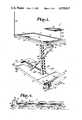
- FIG. 1is a perspective view of the patient lifting table shown in an elevated position.
- FIG. 2is a side elevational view of the patient lifting table in the elevated position.
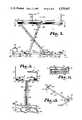
- FIG. 3is an end elevational view of the patient lifting table in the elevated position and having portions in fragmentary representation to show inner details.
- FIG. 4is a side elevational view of the patient lifting table in a lowered position.
- FIG. 5is a bottom view of a lower platform of the patient lifting table taken along lines 5--5, FIG. 2.
- FIG. 6is a bottom view of an upper platform of the patient lifting table of taken lines 6--6, FIG. 2.
- FIG. 7is an enlarged, fragmentary view of the underside of the lower platform.
- FIG. 8is a fragmentary, side elevational view of the portion of the lower platform shown in FIG. 7 and depicting the upper platform lowered against the lower platform.
- FIG. 9is a fragmentary, side elevational view of the lower platform and showing a scissors mechanism in an expanded position.
- FIG. 10is a sectional view taken along lines 10--10, FIG. 9.
- FIG. 11is a sectional view taken along lines 11--11, FIG. 2.
- FIG. 12is a sectional view taken along lines 12--12, FIG. 2.
- FIG. 13is a perspective, fragmentary view of a stop device affixed to the table.
- FIG. 14is an enlarged, fragmentary view of an accessory holder.
- FIG. 1generally indicates a patient lifting table embodying the present invention.
- the lifting table 1includes an upper supportive platform 2, a lower platform 3 located below the upper platform 2 for positioning upon a floor surface, and a scissor linkage mechanism 4 extending between and connected to the upper and lower platforms 2 and 3.
- the lever arm 5is affixed to and extends from a lower end of one of the scissors mechanism links and a means 6 extends between the lower platform 3 and the lever arm 5 and enables raising and lowering of the upper platform 2 relative to the lower platform 3.
- the patient lifting table 1is particularly adapted for human or animal patient use and is predominantly composed of a durable, rust-free material such as stainless steel.
- the upper platform 2is generally rectangular and has a substantially planar surface 8, opposite ends 9 and 10, spaced side walls 11 and 12 and peripherally extending groove 13. The groove 13 is for drainage of bodily fluids.
- An underside 15, FIG. 6, of the upper platform 2has a supportive framework 16 including opposite end members 17 and 18, side members 19 and 20 and intermediate cross braces 21 and 22 to which the planar surface 8 is attached.
- Spaced, parallel track members 24 and 25extend longitudinally along the underside 15 and are intermediately positioned between the side members 19 and 20 and connected to the end members 17 and 18 and the cross braces 21 and 22.
- the track members 24 and 25are in the form of elongate, C-shaped channels, each having an opening 26 toward the longitudinal center line of the upper platform 2 and an interior way 27.
- the track members 24 and 25 and ways 27are utilized in connection with the scissors linkage mechanism 4 as hereinafter described.
- stiffening plates 29extend between and are connected to the ends of the track members 24 and 25.
- Rods forming handrails 30extend from the stiffening plates 29 to the corners of the upper platform 2 for grasping and movement of the table 1 or for use as patient tie-downs.
- the instrument tray support 35includes an instrument tray 37 suitably and removably connected to a holder rod 38.
- the dripstand 36 and holder rod 38each have an L-shaped lower end which is received in an accessory holder, such as a sleeve 40, FIG. 14, such as of cross-sectionally square configuration.
- the lower end of the rod 38extends through the sleeve 40 and has a guide pawl 41 protruding therefrom and received in a generally T-shaped slot 42 of the sleeve 40.
- a coil spring 44encircles the end of the holder 38 and biases the rod and pawl 41 into the T-portion of the slot 42 so that the rod 38 remains upright when selectively moved to the upright position. Additionally, a mounting clip 45 secures the rod when the same is moved to a storage position. In use, the instrument tray support 35 and drip stand 36 are rotated into an upright position as desired and swung downwardly when not in use for out-of-the-way storage.
- the lower platform 3is positioned substantially below and aligned with the upper platform 2 and has a generally planar, obstruction free upper surface 50.
- the lower platform 3 and its opposite ends 51 and 52 and opposite side walls 53 and 54form a rectangular structure.
- An underside 55 of the lower platform 3, FIG. 5,is similarly configured to the underside 15 of the upper platform 2 and includes a framework 57 of spaced end members 58 and 59, side members 60 and 61 and cross braces 62 and 63.
- Track members 65 and 66 of the same configuration as that described in connection with the track members 24 and 25extend between the end members 58 and 59.
- An elongate inner opening 68extends longitudinally through lower platform 3 and has one end 69, FIG.
- the scissors linkage mechanism 4extends between and is connected to the upper and lower platforms 2 and 3 to provide substantially straight upward and downward movement of the upper platform 2 relative to the lower platform 3.
- the scissors linkage mechanism 4includes generally X-shaped when extended, straight crossing arms or legs, such as a center link arm or member 73 having an upper end 74 and a lower end 75, FIGS. 2 and 3.
- the upper end 74includes a rod or shaft 77, FIG. 6, extending therethrough and having opposite ends 78 extending through the spaced upper track member 24 and 25 and affixed thereto as by fasteners adjacent the end member 17.
- the upper end 74is notched, FIG. 8, for clearance upon swinging of the center leg members 73 relative to the upper platform 2, as when unfolding.
- wheels or rollers 80are rotatably mounted to the ends of the axle or rod 79 and are fitted within the ways 27 of the track members 65 and 66 so that the lower end 75 slides respectively forwardly and rearwardly upon lowering and raising.
- Second or crossing link members 83include in the illustrated example, FIG. 1, a pair of links 84 and 85.
- the links 84 and 85respectively have upper and lower ends 86 and 87 with the upper ends 86, FIG. 12, having an axle or rod 89 extending transversely therethrough and having wheels or rollers 90 rotatably mounted on the axle ends.
- the wheels or rollers 90are received in the ways 27 of the upper track members 24 and 25 whereby the upper ends 86 of the link members 84 and 85 roll or slide longitudinally in the track members 24 and 25 upon raising and lowering the upper platform 2 relative to the lower platform 3.
- an axle or rod 91extends transversely through the lower ends 87 and its opposite end portions are received in journals 92 securely mounted to connecting plates 93.
- the plates 93are in turn rigidly affixed to the track members 65 and 66 as by bolts 94, thereby swingably affixing the lower ends 87 of the link members 84 and 85 to the lower platform framework 57.
- mid portions of the respective members 73, 84 and 85are interconnected by a transverse axle or rod 96, FIG. 1, whereby upon movement of the upper platform 2 toward and away from the lower platform 3, the center link member 73 tends to swing or pivot relative to the link member 84 and 85.
- Respective lever armsare affixed to and extend from the lower ends 87 of the link members 84 and 85 and connect to the means 6 extending between the lower platform 3 and the lever arm.
- the means 6is extensible and retractable to cause raising and lowering of the upper platform 2 relative to the lower platform 3.
- an ear-shaped lever arm or bell crankFIGS. 9 and 10 extends upwardly of each of the lower ends 87 and protrudes toward the platform 72.
- the bell crank 98is of precise dimensions so as to achieve a specified throw or rotative angle of the link members 84 and 85 for full extension and retraction of the upper platform 2 relative to the lower platform 3.
- a connecting shaft 100extends between outer portions of the bell cranks 98 and its opposite ends are secured thereto as by nuts 101, FIG. 9.
- the connecting shaft 100is positioned below the level of the axle or shaft 91 throughout its full range of travel, FIGS. 8 and 9.
- the means 6, in the illustrated example,includes a single action power fluid ram 104 having a cylinder 105 and a piston 106. Both ends of the ram 104 are swingably mounted, respectively to the lower platform framework 57 and to the connecting shaft 100 and in the illustrated example FIG. 8, the piston 106 includes an end eye 108 holding a bushing 109 through which the connecting shaft 100 extends. Accordingly, the cylinder end 105 of the ram 104 is pivotally connected to the framework 57.
- a support for the cylinder end 105is formed of a sturdy cross brace 111 extending between and connected to the side members 60 and 61 and has out turned flanges 112 for strength.
- Spaced ears 114are positioned on opposite sides of the end of the cylinder end 105 and a pin 115, FIGS. 8 and 9, extends through the ears 114 and the end 105 of the ram 104 to rotatably secure the same to the framework 57.
- Sufficient sturdiness of the cross brace 111 and flanges 112is required, as the ram 104 must push hard against the cross brace 111 while exerting force against the bell cranks 98 to raise the scissors linkage mechanism 4.
- a pump meansis associated with the ram 104 to supply pressurized fluid.
- a pump bracket 117is mounted between the cross brace 111 and the end member 58 to provide support at one corner of the lower platform 3 for an end of a manual pump 119.
- the pump 119is of conventional configuration and is further mounted at a front bracket 120 so that the pump is securely mounted adjacent the end 51 of the lower platform 3.
- the pump 119projects above the upper surface 50 of the lower platform 3 and is protected by a suitable cover or guard 122, such as of rectangular configuration, FIG. 1, which is attached to the lower platform adjacent the end 51.
- a slot 123extends a portion of the cover 122 and provides for extension of a pump lever 124 having an end pad 125 suitable for foot operation and a return spring 126.
- Suitable conduit or tubing 127connects the outlet of the pump 119 with the ram 104 for carrying pressurized hydraulic fluid from the pump 119.
- the pump 119contains an internal one-way check or relief valve (not shown) which is actuated by a valve lever 128, FIGS. 8 and 9.
- a stop 129 in the form of a plate or bracketis mounted immediately below the valve lever 128 so that excessive foot pressure on the lever does not over stress the internal valve parts.
- casters or wheels 131are mounted on rotatable shafts 132 and are pivotally affixed in sockets 133 mounted at the four corners of the lower platform 123. Bumpers 134 are also located at the corners for protection during movement.
- a stop 136is provided to prevent undesired movement of the lifting table 1 about the floor, as when performing operations or leaving the table unattended.
- the stop 136is of the kick stand nature and comprises an elongate rod 137 extending between journals in brackets 137' depending from the opposite side walls 53 and 54.
- Short shafts forming feet 138 and 139each have a rubber tipped cap 140 and when the rod 137 is rotated, engage the floor.
- a foot operated lever 142is positioned outwardly of the side member 54 and is spring loaded to a retracted position by a coil spring 143 sleeved about the end of the rod 137 and having its opposite ends respectively mounted to the bracket 137' and the lever 142.
- L-shaped brackets 145are secured to the framework 57 at appropriate locations.
- the feet 138 and 139are longer than the combined length of the casters or wheels 131 and shafts 132 so that when foot pressure is applied to the stop lever 142, the feet 138 and 139 rotate into ground engagement and lift the table 1 upwardly a slight amount to remove weight from the adjacent casters or wheels 131. This prevents free rolling movement.
- the foot lever 142is simply rotated in the opposite direction so that the feet 138 and 139 are removed from ground contact and the adjacent casters or wheels 131 return to engagement with the floor.
- a full range of heights of the upper platform 2 relative to the floor surfacecan be achieved from a range of about 39 inches, which is the average operating table height, to as low as possible.
- the average cage base heightis located 8 to 9 inches above the floor and in an embodiment made according to the present invention, the upper platform 2 is 91/2 inches above the floor in the collapsed position.
- the scissors linkage mechanism 4permits the upper platform to rest horizontally upon the lower platform 3 just a very short distance above the floor surface.
- a comatose patientneed only be lifted a very short distance from the floor onto the upper platform 2, which persons of average strength are readily capable of performing.
- a doctor or medical technicianmerely places the patient on the upper platform and then, placing his foot upon the pump lever 124, pumps up the upper platform 2 to the desired height.
- Extension of the ram 104causes the piston end eye 108 to urge the shaft outwardly and push against the bell cranks 98, thus causing the bell cranks 98 to swing about the axle or rod 91.
- the link members 84 and 85swing upwardly with the upper ends 86 sliding.
- the scissors linkage mechanism 4provides both longitudinal and lateral stability to the upper platform 2 relative to the lower platform 3.
- the technicianmerely depresses the valve lever 128 and the weight of the platform 2 causes it to slowly lower.
Landscapes
- Life Sciences & Earth Sciences (AREA)
- Health & Medical Sciences (AREA)
- Engineering & Computer Science (AREA)
- Veterinary Medicine (AREA)
- General Health & Medical Sciences (AREA)
- Animal Behavior & Ethology (AREA)
- Public Health (AREA)
- Geology (AREA)
- Mechanical Engineering (AREA)
- Structural Engineering (AREA)
- Wood Science & Technology (AREA)
- Zoology (AREA)
- Animal Husbandry (AREA)
- Nursing (AREA)
- Biomedical Technology (AREA)
- Accommodation For Nursing Or Treatment Tables (AREA)
Abstract
Description
This is a continuation-in-part of application Ser. No. 313,086, filed Oct. 20, 1981, now abandoned.
This invention relates to lift tables and particularly to those tables employing a scissor linkage mechanism to vary the distance between an upper platform and a lower platform.
Prior art devices for elevating objects, human patients or animals from a lowered position to an elevated position have generally been designed for a single specific purpose and usually are confined to a specific range of adjustment between a lower and an elevated position. For example, in the medical field, a patient stretcher used in ambulances is generally adapted for adjustment between a lowered position in which a patient can be lifted onto the stretcher with minimal lifting or handling and a higher, second position to facilitate transfer to an ambulance. Stretchers are also normally suitable for transporting the patient from the ambulance to a hospital bed. The stretchers have only a small range of height adjustment which usually necessitates lifting the patient from the ground surface onto the stretcher. While the stretcher can be used for transporting the patient, the patient must ultimately be lifted a second or even a third time to transfer the patient to a bed or an operating table which is at a more convenient height for treatment. For patients suffering from broken bones and/or internal injuries, such additional handling for transporation and lifting purposes may create further injuries.
Many machinist's tables employ a scissors linkage mechanism but because enormous weights must sometimes be lifted, these tables are often extremely heavy and complex in construction. Moreover, the complexity of the tables mitigates against medical usage, as it is often difficult to thoroughly clean such tables. Greasy, oily or otherwise unsanitary mechanisms are often exposed between the upper and lower platforms, making the device unsuitable for either hospital or veterinary use.
In view of the above, the principal objects of the present invention are: to provide a patient lifting table having a full range of height adjustment from a lowered position to an elevated position and including any position therebetween; to provide such a patient lifting table having a downward position situated only a small distance above a floor surface and which facilitates the placement of the patient onto the table; to provide such a patient lifting table in which a downward position is only a few inches above the floor surface; to provide such a patient lifting table in which an upper platform may rest only upon a lower platform for maximum downward travel; to provide such a patient lifting table which is useful for patient transportation and operating; to provide such a patient lifting table having planar, unobstructed surfaces on both upper and lower platforms for ease of cleaning and maintaining sanitary conditions; to provide such a patient lifting table which has a handy, foot operated pump and leaves both of the operator's hands free for working on the patient; to provide such a patient lifting table which is stable and sturdy in use and able to support moderate weights; and to provide such a patient lifting table which is relatively inexpensive, sturdy and efficient in use and particularly well adapted for the intended purpose.
Other objects and advantages of this invention will become apparent from the following description taken in conjunction with the accompanying drawings wherein are set forth, by way of illustration and example, certain embodiments of this invention.
FIG. 1 is a perspective view of the patient lifting table shown in an elevated position.
FIG. 2 is a side elevational view of the patient lifting table in the elevated position.
FIG. 3 is an end elevational view of the patient lifting table in the elevated position and having portions in fragmentary representation to show inner details.
FIG. 4 is a side elevational view of the patient lifting table in a lowered position.
FIG. 5 is a bottom view of a lower platform of the patient lifting table taken alonglines 5--5, FIG. 2.
FIG. 6 is a bottom view of an upper platform of the patient lifting table of takenlines 6--6, FIG. 2.
FIG. 7 is an enlarged, fragmentary view of the underside of the lower platform.
FIG. 8 is a fragmentary, side elevational view of the portion of the lower platform shown in FIG. 7 and depicting the upper platform lowered against the lower platform.
FIG. 9 is a fragmentary, side elevational view of the lower platform and showing a scissors mechanism in an expanded position.
FIG. 10 is a sectional view taken alonglines 10--10, FIG. 9.
FIG. 11 is a sectional view taken alonglines 11--11, FIG. 2.
FIG. 12 is a sectional view taken alonglines 12--12, FIG. 2.
FIG. 13 is a perspective, fragmentary view of a stop device affixed to the table.
FIG. 14 is an enlarged, fragmentary view of an accessory holder.
As required, detailed embodiments of the present invention are disclosed herein, however, it is to be understood that the disclosed embodiments are merely exemplary of the invention which may be embodied in various forms. Therefore, specific structural and functional details disclosed herein are not to be interpreted as limiting, but merely as a basis for the claims and as a representative basis for teaching one skilled in the art to variously employ the present invention in virtually any appropriately detailed structure.
Referring to the drawings in more detail:
The reference numeral 1, FIG. 1 generally indicates a patient lifting table embodying the present invention. The lifting table 1 includes an uppersupportive platform 2, alower platform 3 located below theupper platform 2 for positioning upon a floor surface, and ascissor linkage mechanism 4 extending between and connected to the upper andlower platforms lever arm 5 is affixed to and extends from a lower end of one of the scissors mechanism links and ameans 6 extends between thelower platform 3 and thelever arm 5 and enables raising and lowering of theupper platform 2 relative to thelower platform 3.
In the illustrated example, the patient lifting table 1 is particularly adapted for human or animal patient use and is predominantly composed of a durable, rust-free material such as stainless steel. Theupper platform 2 is generally rectangular and has a substantiallyplanar surface 8,opposite ends side walls groove 13. Thegroove 13 is for drainage of bodily fluids. Anunderside 15, FIG. 6, of theupper platform 2 has asupportive framework 16 includingopposite end members side members 19 and 20 andintermediate cross braces planar surface 8 is attached. Spaced,parallel track members underside 15 and are intermediately positioned between theside members 19 and 20 and connected to theend members cross braces
In the illustrated example, FIG. 12, thetrack members opening 26 toward the longitudinal center line of theupper platform 2 and aninterior way 27. Thetrack members ways 27 are utilized in connection with thescissors linkage mechanism 4 as hereinafter described.
At theopposite ends stiffening plates 29 extend between and are connected to the ends of thetrack members Rods forming handrails 30 extend from thestiffening plates 29 to the corners of theupper platform 2 for grasping and movement of the table 1 or for use as patient tie-downs.
Making the lifting table 1 particularly useful for patient or hospital use are accessories such as aninstrument tray support 35 and anintravenous drip stand 36. Theinstrument tray support 35 includes aninstrument tray 37 suitably and removably connected to aholder rod 38. Thedripstand 36 andholder rod 38 each have an L-shaped lower end which is received in an accessory holder, such as asleeve 40, FIG. 14, such as of cross-sectionally square configuration. The lower end of therod 38 extends through thesleeve 40 and has aguide pawl 41 protruding therefrom and received in a generally T-shaped slot 42 of thesleeve 40. Acoil spring 44 encircles the end of theholder 38 and biases the rod andpawl 41 into the T-portion of theslot 42 so that therod 38 remains upright when selectively moved to the upright position. Additionally, amounting clip 45 secures the rod when the same is moved to a storage position. In use, the instrument traysupport 35 anddrip stand 36 are rotated into an upright position as desired and swung downwardly when not in use for out-of-the-way storage.
Thelower platform 3 is positioned substantially below and aligned with theupper platform 2 and has a generally planar, obstruction freeupper surface 50. In the illustrated example, thelower platform 3 and itsopposite ends opposite side walls lower platform 3, FIG. 5, is similarly configured to theunderside 15 of theupper platform 2 and includes a framework 57 of spacedend members side members 60 and 61 andcross braces members track members end members inner opening 68 extends longitudinally throughlower platform 3 and has oneend 69, FIG. 1, terminating at theend member 59 and anotheropening end 70 terminating substantially equidistantly between thecross brace 62 and theend member 58. Lower portions, described below, of thescissor linkage mechanism 4 extend upwardly through thecenter opening 68 for ultimate connection with theupper platform 2.
Thescissors linkage mechanism 4 extends between and is connected to the upper andlower platforms upper platform 2 relative to thelower platform 3. In the illustrated example, thescissors linkage mechanism 4 includes generally X-shaped when extended, straight crossing arms or legs, such as a center link arm ormember 73 having anupper end 74 and alower end 75, FIGS. 2 and 3. Theupper end 74 includes a rod orshaft 77, FIG. 6, extending therethrough and havingopposite ends 78 extending through the spacedupper track member end member 17. Theupper end 74 is notched, FIG. 8, for clearance upon swinging of thecenter leg members 73 relative to theupper platform 2, as when unfolding. Thelower end 75 of the centerlink member arm 73, FIG. 11, similarly has an axle or rod extending therethrough but instead has means facilitating sliding of thelower end 75 relative to thelower platform 3. In the illustrated example, wheels or rollers 80 are rotatably mounted to the ends of the axle orrod 79 and are fitted within theways 27 of thetrack members lower end 75 slides respectively forwardly and rearwardly upon lowering and raising.
Second or crossinglink members 83 include in the illustrated example, FIG. 1, a pair oflinks links rod 89 extending transversely therethrough and having wheels orrollers 90 rotatably mounted on the axle ends. The wheels orrollers 90 are received in theways 27 of theupper track members link members track members upper platform 2 relative to thelower platform 3. The lower ends 87, FIG. 10, of thelink members lower platform 3 and in the illustrated example, an axle orrod 91 extends transversely through the lower ends 87 and its opposite end portions are received injournals 92 securely mounted to connectingplates 93. Theplates 93 are in turn rigidly affixed to thetrack members bolts 94, thereby swingably affixing the lower ends 87 of thelink members link members center link member 73 in generally X-shaped or crossing relationship, mid portions of therespective members rod 96, FIG. 1, whereby upon movement of theupper platform 2 toward and away from thelower platform 3, thecenter link member 73 tends to swing or pivot relative to thelink member
Respective lever arms are affixed to and extend from the lower ends 87 of thelink members means 6 extending between thelower platform 3 and the lever arm. In the illustrated example, themeans 6 is extensible and retractable to cause raising and lowering of theupper platform 2 relative to thelower platform 3. In the illustrated example, an ear-shaped lever arm or bell crank, FIGS. 9 and 10, extends upwardly of each of the lower ends 87 and protrudes toward the platform 72. Thebell crank 98 is of precise dimensions so as to achieve a specified throw or rotative angle of thelink members upper platform 2 relative to thelower platform 3. A connectingshaft 100 extends between outer portions of the bell cranks 98 and its opposite ends are secured thereto as bynuts 101, FIG. 9. Preferably, the connectingshaft 100 is positioned below the level of the axle orshaft 91 throughout its full range of travel, FIGS. 8 and 9.
Themeans 6, in the illustrated example, includes a single actionpower fluid ram 104 having acylinder 105 and apiston 106. Both ends of theram 104 are swingably mounted, respectively to the lower platform framework 57 and to the connectingshaft 100 and in the illustrated example FIG. 8, thepiston 106 includes anend eye 108 holding abushing 109 through which the connectingshaft 100 extends. Accordingly, thecylinder end 105 of theram 104 is pivotally connected to the framework 57. In the illustrated example FIGS. 7 and 8, a support for thecylinder end 105 is formed of a sturdy cross brace 111 extending between and connected to theside members 60 and 61 and has out turned flanges 112 for strength. Spacedears 114 are positioned on opposite sides of the end of thecylinder end 105 and apin 115, FIGS. 8 and 9, extends through theears 114 and theend 105 of theram 104 to rotatably secure the same to the framework 57. Sufficient sturdiness of the cross brace 111 and flanges 112 is required, as theram 104 must push hard against the cross brace 111 while exerting force against the bell cranks 98 to raise thescissors linkage mechanism 4.
A pump means is associated with theram 104 to supply pressurized fluid. In the illustrated example FIG. 7, apump bracket 117 is mounted between the cross brace 111 and theend member 58 to provide support at one corner of thelower platform 3 for an end of amanual pump 119. Thepump 119 is of conventional configuration and is further mounted at afront bracket 120 so that the pump is securely mounted adjacent theend 51 of thelower platform 3. Thepump 119 projects above theupper surface 50 of thelower platform 3 and is protected by a suitable cover orguard 122, such as of rectangular configuration, FIG. 1, which is attached to the lower platform adjacent theend 51. Aslot 123 extends a portion of thecover 122 and provides for extension of apump lever 124 having anend pad 125 suitable for foot operation and areturn spring 126.
Suitable conduit ortubing 127 connects the outlet of thepump 119 with theram 104 for carrying pressurized hydraulic fluid from thepump 119. Thepump 119 contains an internal one-way check or relief valve (not shown) which is actuated by avalve lever 128, FIGS. 8 and 9. Astop 129 in the form of a plate or bracket is mounted immediately below thevalve lever 128 so that excessive foot pressure on the lever does not over stress the internal valve parts.
For movement about a floor surface, casters orwheels 131 are mounted onrotatable shafts 132 and are pivotally affixed insockets 133 mounted at the four corners of thelower platform 123.Bumpers 134 are also located at the corners for protection during movement.
Astop 136, FIG. 13, is provided to prevent undesired movement of the lifting table 1 about the floor, as when performing operations or leaving the table unattended. In the illustrated example, thestop 136 is of the kick stand nature and comprises anelongate rod 137 extending between journals in brackets 137' depending from theopposite side walls shafts forming feet cap 140 and when therod 137 is rotated, engage the floor. A foot operatedlever 142 is positioned outwardly of theside member 54 and is spring loaded to a retracted position by acoil spring 143 sleeved about the end of therod 137 and having its opposite ends respectively mounted to the bracket 137' and thelever 142. To maintain rigidity of therod 137, L-shapedbrackets 145 are secured to the framework 57 at appropriate locations. Thefeet wheels 131 andshafts 132 so that when foot pressure is applied to thestop lever 142, thefeet wheels 131. This prevents free rolling movement. To release the operation of thestop 132, thefoot lever 142 is simply rotated in the opposite direction so that thefeet wheels 131 return to engagement with the floor.
In the use of the present invention, a full range of heights of theupper platform 2 relative to the floor surface can be achieved from a range of about 39 inches, which is the average operating table height, to as low as possible. For example, for use in the veterinary field, the average cage base height is located 8 to 9 inches above the floor and in an embodiment made according to the present invention, theupper platform 2 is 91/2 inches above the floor in the collapsed position. Thescissors linkage mechanism 4 permits the upper platform to rest horizontally upon thelower platform 3 just a very short distance above the floor surface. Thus, a comatose patient need only be lifted a very short distance from the floor onto theupper platform 2, which persons of average strength are readily capable of performing.
For use, a doctor or medical technician merely places the patient on the upper platform and then, placing his foot upon thepump lever 124, pumps up theupper platform 2 to the desired height. Extension of theram 104 causes thepiston end eye 108 to urge the shaft outwardly and push against the bell cranks 98, thus causing the bell cranks 98 to swing about the axle orrod 91. Thelink members scissors linkage mechanism 4 provides both longitudinal and lateral stability to theupper platform 2 relative to thelower platform 3. To return theupper platform 2 to the lower position, the technician merely depresses thevalve lever 128 and the weight of theplatform 2 causes it to slowly lower.
It is to be understood that while certain forms of the present invention have been illustrated and described herein, it is not to be limited to the specific forms or arrangement of parts described and shown.
Claims (6)
1. A veterinary table comprising:
(a) an upper platform having a planar, patient supportive upper surface and an underside including track means;
(b) a lower platform positioned below and aligned with said upper platform and having a generally planar, obstruction free upper surface for said upper platform to rest upon and an underside;
(c) wheels mounted to said lower platform for movement over a floor surface;
(d) a track means mounted in said lower platform underside;
(e) a scissor linkage mechanism extending between and connected to said upper and lower platforms to provide straight upward and downward movement of said upper platform relative to said lower platform; said scissor linkage mechanism including a center link member having an upper end pivotally affixed to said upper platform underside and a lower end slidable in said lower platform track means, and spaced link members with said center link member extending therebetween; said spaced link members having upper ends slidable in said upper platform track means and lower ends pivotally affixed to said lower platform underside; said center link member and said spaced link members having pivotally interconnected mid-portions;
(f) said lower ends of said spaced link members being mounted below said lower platform upper surface and having bell crank arms extending angularly thereform and supporting a rod extending transversely between said bell crank arms;
(g) a power fluid ram mounted in said lower platform and aligned with said lower platform track means, said ram having one end pivotally connected to said lower platform and a second end pivotally connected to said rod, said rod being extensible and retractible to cause upward and downward swinging of said spaced link members and raising and lowering of said upper platform; said ram being mounted entirely below said lower platform upper surface for concealment and whereby said upper platform may rest against said lower platform; and
(h) a manual pump and relief valve mounted on said lower platform adjacent said ram.
2. The veterinary lift table set forth in claim 1 including:
(a) a stop secured to said lower platform and having lever means therewith operable to remove weight from some of said wheels to stop movement over said floor surface.
3. A veterinary lift table comprising:
(a) a rectangular, patient supportive upper platform having a substantially planar upper surface, opposite ends and an underside frame having spaced, longitudinal channels forming tracks;
(b) a rectangular lower platform of substantially equal dimensions to said upper platform and having a generally planar, obstruction free upper surface, opposite ends and an underside frame having spaced longitudinal channels forming tracks;
(c) wheels mounted on said lower platform for movement over a ground surface;
(d) stop means mounted on said lower platform and engageable with said ground surface for selectively inhibiting movement;
(e) a scissor linkage mechanism extending between and connected to said upper and lower platforms to provide straight upward and downward movement of said upper platform relative to said lower platform; said scissor linkage mechanisms including a center link arm having an upper end pivotally affixed to said upper platform frame and a lower end having wheels rotatably connected thereto and received in said lower platform tracks; and spaced link arms having upper ends with wheels rotatably connected thereto and received in said upper platform tracks and lower ends pivotally affixed to said lower platform frame; said center link arm and said spaced link arms crossing and having pivotally interconnected mid-portions;
(f) bell crank arms connected to and extending angularly from said spaced link arms lower ends, said bell crank arms having a rod extending therebetween and positioned below said spaced link rams lower ends;
(g) an extensible and retractible power fluid ram positioned in said lower platform below and concealed by the surface thereof and having one end pivotally affixed to said frame and a second end pivotally affixed to said rod for swinging said spaced link arms upwardly and downwardly upon respective extension and retraction of said ram; and
(h) a foot operated pump mounted on said lower platform at one end of said lower platform adjacent said ram and having a cover concealing said pump;
(i) a relief valve mounted at said one end of said lower platform and having a foot operable lever thereon to release pressure in said ram and facilitate lowering of said upper platform against said lower platform.
4. A veterinary table comprising:
(a) an upper platform having a planar, patient supportive, upper surface;
(b) a lower platform positioned below and aligned with said upper platform and having a generally planar, obstruction free, upper surface, for said upper platform to rest upon;
(c) a scissors linkage mechanism extending between and connected to said upper and lower platforms to provide straight upward and downward movement of said upper platform relative to said lower platform; said scissors linkage mechanism including a center link member having an upper end pivotally affixed to said upper platform and a lower end slidably mounted on said lower platform, and spaced link members with said center link member extending therebetween; said spaced link members having upper ends slidably mounted on said upper platform and lower ends pivotally affixed to said lower platform; one of said spaced link members having a lower end with a lever arm affixed thereto and extending therefrom;
(d) actuation means engaging said scissors linkage mechanism and operable to vary an extension of same and to cause selected raising and lowering of said upper platform relative to said lower platform;
(i) said actuation means including a power fluid ram pivotally connected to, and extending between, said lower platform and said lever arm and extensible and retractable to selectively cause said raising and lowering of said upper platform with respect to said lower platform.
5. The table as set forth in claim 4 wherein:
(a) said lower platform has a frame and an underside; said lower platform having first and second end positions;
(b) said ram has one end pivotally connected to said lower platform frame at said first end; and
(c) said ram is positioned entirely below said upper surface.
6. The lifting table set forth in claim 5 wherein:
(a) said lower platform has opposite ends, spaced sides, and a generally planar surface;
(b) an elongate opening extends through said lower platform; and, said scissors linkage mechanism has lower end portions extending through said opening;
(c) said ram is mounted at one of said ends of said lower platform and extends under said planar surface;
(d) said actuation means includes a pump mounted at said one of said ends of said lower platform;
(e) said pump includes a pump lever extending above said planar surface of said lower platform; and
(f) said pump lever has a pad thereon for foot actuation for raising of said upper platform.
Applications Claiming Priority (2)
| Application Number | Priority Date | Filing Date | Title |
|---|---|---|---|
| AUPE6168 | 1980-10-22 | ||
| AU616880 | 1980-10-22 |
Related Parent Applications (1)
| Application Number | Title | Priority Date | Filing Date |
|---|---|---|---|
| US06313086Continuation-In-Part | 1981-10-20 |
Publications (1)
| Publication Number | Publication Date |
|---|---|
| US4558847Atrue US4558847A (en) | 1985-12-17 |
Family
ID=3696676
Family Applications (1)
| Application Number | Title | Priority Date | Filing Date |
|---|---|---|---|
| US06/465,580Expired - LifetimeUS4558847A (en) | 1980-10-22 | 1983-02-10 | Patient lifting table |
Country Status (1)
| Country | Link |
|---|---|
| US (1) | US4558847A (en) |
Cited By (64)
| Publication number | Priority date | Publication date | Assignee | Title |
|---|---|---|---|---|
| EP0399618A1 (en)* | 1989-05-22 | 1990-11-28 | Oostwoud Holding B.V. | Bed |
| FR2675689A1 (en)* | 1991-04-23 | 1992-10-30 | Baldisserri Jean | Veterinary surgery table |
| US5271113A (en)* | 1992-04-28 | 1993-12-21 | Johnny White | Electromechanical ambulance cot conversion kit |
| EP0601695A3 (en)* | 1992-09-24 | 1995-02-15 | Snell Elizabeth | Operating table. |
| GB2301282A (en)* | 1992-09-24 | 1996-12-04 | Snell Elizabeth | Height-adjustable veterinary table |
| ES2110340A1 (en)* | 1994-06-09 | 1998-02-01 | Bresco Arturo Puig | Improved bed |
| US5826286A (en)* | 1996-10-09 | 1998-10-27 | Vssi, Inc. | Veterinary surgical table |
| US6101956A (en)* | 1997-12-16 | 2000-08-15 | Keil; Charles C. | Mobile veterinary treatment prep table |
| US6199508B1 (en) | 1998-06-22 | 2001-03-13 | Theresa Miale | Animal lift and transport apparatus |
| US6230662B1 (en) | 1998-06-22 | 2001-05-15 | Theresa Miale | Animal lift and transport apparatus and method for using the same |
| CN1085183C (en)* | 1996-02-20 | 2002-05-22 | 加里·克莱夫·哈姆 | Conveyor belt lifting device |
| US6516478B2 (en) | 2001-05-31 | 2003-02-11 | Health & Technology, Inc. | Adjustable height bed |
| US20040026991A1 (en)* | 2002-08-08 | 2004-02-12 | Asmo Co., Ltd. | Traction control system |
| US20040025795A1 (en)* | 1998-06-22 | 2004-02-12 | Miale Theresa M. | Animal lift and transport apparatus and method for using the same |
| US20040094077A1 (en)* | 1999-11-03 | 2004-05-20 | Stone Robert M. | Safety toe-sensor for lift table |
| US6772456B2 (en) | 1995-09-13 | 2004-08-10 | Hill-Rom Services, Inc. | Portable device for patient pullup, rollover, and transfer and methods thereof |
| US20040194734A1 (en)* | 2003-03-21 | 2004-10-07 | Fisher Larry A. | Animal raising and lowering system |
| WO2005044714A1 (en)* | 2003-11-07 | 2005-05-19 | Maarten Van Dalsen | Load displacer |
| US20050200091A1 (en)* | 2004-03-12 | 2005-09-15 | Mitchell Knecole A. | Portable tire and wheel lifting apparatus |
| US20060075558A1 (en)* | 2004-09-24 | 2006-04-13 | Lambarth Clifford E | Ambulance cot and hydraulic elevating mechanism therefor |
| US20060168730A1 (en)* | 2002-09-06 | 2006-08-03 | Menkedick Douglas J | Hospital bed |
| US7111338B2 (en) | 2002-06-17 | 2006-09-26 | Hill-Rom Services, Inc. | Apparatus for pulling patient up in bed |
| US20060241408A1 (en)* | 2005-02-04 | 2006-10-26 | General Electric Company | Method and apparatus for a multi-modality imaging system |
| US20060265807A1 (en)* | 2004-06-14 | 2006-11-30 | Earl Choy | Charging system for recharging a battery of an electrohydraulically powered lift ambulance cot with an electrical system of an emergency vehicle |
| US20070245977A1 (en)* | 1997-12-16 | 2007-10-25 | Midmark Corporation | Veterinary procedure table with scale |
| US7290299B2 (en) | 2004-01-09 | 2007-11-06 | Votel Thomas W | Device and method for positioning patients |
| US20070295285A1 (en)* | 2006-06-05 | 2007-12-27 | Wahl Clipper Corporation | Pet grooming stand |
| US20080276372A1 (en)* | 2004-09-24 | 2008-11-13 | Stryker Corporation | Ambulance cot with retractable head section and control system therefor |
| US20090044762A1 (en)* | 2007-08-14 | 2009-02-19 | Midmark Corporation | Grille for veterinary procedure tables |
| US20090172883A1 (en)* | 2004-06-14 | 2009-07-09 | Ferno-Washington, Inc. | Electro-hydraulically powered lift ambulance cot |
| US20090255483A1 (en)* | 2008-04-14 | 2009-10-15 | Midmark Corporation | Veterinary procedure table |
| US7725964B2 (en) | 2004-08-27 | 2010-06-01 | Hill-Rom Services, Inc. | Apparatus with patient adjustment device coupled to architectural system |
| US20100242174A1 (en)* | 2008-12-11 | 2010-09-30 | Morrison Sr Paul | Adjustable Height Lift Platform for Surgical Procedures |
| US20120006283A1 (en)* | 2010-07-09 | 2012-01-12 | Katz Andrew S | Animal handling station |
| US8333159B2 (en) | 2010-10-06 | 2012-12-18 | Schroer Manufacturing Company | Veterinary table assembly with rotatable table |
| US8336138B2 (en) | 2003-03-18 | 2012-12-25 | Hill-Rom Services, Inc. | Radial arm system for patient care equipment |
| USD706426S1 (en) | 2011-09-09 | 2014-06-03 | Schroer Manufacturing Company | Veterinary table |
| US8752675B2 (en)* | 2006-06-21 | 2014-06-17 | Stertil B.V. | Vehicle elevator and lift therein |
| CN103879921A (en)* | 2014-03-12 | 2014-06-25 | 亿丰洁净科技江苏股份有限公司 | Novel experiment lifting table |
| US20140265254A1 (en)* | 2011-10-13 | 2014-09-18 | Kayaba Industry Co., Ltd. | Conveyance cart |
| US8839725B2 (en)* | 2009-01-22 | 2014-09-23 | Fredricks Design, Inc. | Table apparatus |
| US9107494B2 (en)* | 2013-03-14 | 2015-08-18 | Electrolux Home Products, Inc. | Refrigerator with a lift mechanism including at least one pivot arm |
| US20150283017A1 (en)* | 2014-04-08 | 2015-10-08 | Harris Medical, Llc | Mobile transportation device convertible to an examination table and for use in a motor vehicle and method thereof |
| US20150289641A1 (en)* | 2014-04-14 | 2015-10-15 | Mustafa A. Ergun | Height adjustable desktop work surface |
| USD742526S1 (en) | 2014-06-23 | 2015-11-03 | Schroer Manufacturing Company | Veterinary table |
| US20150342805A1 (en)* | 2014-04-08 | 2015-12-03 | Harris Medical, Llc | Mobile transportation device convertible to a trendelenburg table and for use in a motor vehicle and method thereof |
| CN105616078A (en)* | 2016-03-31 | 2016-06-01 | 粟广欢 | Lifting platform in ambulance |
| US9371083B1 (en)* | 2014-12-16 | 2016-06-21 | Acu-Pac, Inc. | Collapsible stackable storage cart |
| US9554644B2 (en) | 2012-05-24 | 2017-01-31 | Varidesk, Llc | Adjustable desk platform |
| US9913697B1 (en)* | 2016-10-30 | 2018-03-13 | Eric A. DeVeaux | Portable workstation for healthcare professionals |
| US9999489B1 (en) | 2017-09-14 | 2018-06-19 | Theodore E. Kern, Sr. | Animal lifting table with offloading ramp |
| US10064383B1 (en)* | 2018-01-11 | 2018-09-04 | Michele L. Valdespee | Litter lift |
| US20190330034A1 (en)* | 2018-04-27 | 2019-10-31 | California Manufacturing & Engineering Company, Llc | Work platform with extension deck and work step |
| US10542817B2 (en) | 2015-09-24 | 2020-01-28 | Ergotron, Inc. | Height adjustable device |
| US10561555B2 (en) | 2015-06-24 | 2020-02-18 | Hill-Rom S.A.S. | Patient positioning apparatus and method |
| US10602840B2 (en) | 2015-10-08 | 2020-03-31 | Ergotron, Inc. | Height adjustable table |
| CN110972983A (en)* | 2019-12-24 | 2020-04-10 | 安徽省天长市周氏羊业有限公司 | All-round shaving apparatus of safe formula wool |
| CN111993338A (en)* | 2020-08-26 | 2020-11-27 | 山西医科大学 | A kind of replacement device and fixing device of molybdenum technetium generator |
| CN113440341A (en)* | 2021-07-30 | 2021-09-28 | 中国人民解放军新疆军区总医院 | Modular plateau critical care single cabin convenient to manage and transport |
| US20220265411A1 (en)* | 2021-02-23 | 2022-08-25 | Olympic Veterinary Corporation | Veterinary procedure table sysyem |
| US11447378B2 (en) | 2018-12-17 | 2022-09-20 | Terex South Dakota, Inc. | Access deck assembly and handle assembly for an aerial work platform of a vehicle |
| US11800927B1 (en) | 2015-01-24 | 2023-10-31 | Office Kick, Inc. | Desktop workspace that adjusts vertically |
| US11903883B2 (en) | 2015-05-29 | 2024-02-20 | Oakworks, Inc. | Support platform for body treatment |
| US12252380B1 (en)* | 2018-04-27 | 2025-03-18 | California Manufacturing & Engineering Company, Llc | Work platform having attached movable work step |
Citations (41)
| Publication number | Priority date | Publication date | Assignee | Title |
|---|---|---|---|---|
| US214224A (en)* | 1879-04-08 | Improvement in fire-escape ladders | ||
| US366365A (en)* | 1887-07-12 | Alexander | ||
| US682932A (en)* | 1900-09-06 | 1901-09-17 | Israel Louis Dreeben | Truck. |
| US1190034A (en)* | 1916-01-11 | 1916-07-04 | Steve Starcovic | Extensible fire-ladder. |
| US2043887A (en)* | 1935-05-16 | 1936-06-09 | John L Dement | Furniture truck |
| GB523334A (en)* | 1938-12-31 | 1940-07-11 | Albert Phillips Ltd | Improvements in or relating to bedsteads |
| US2370887A (en)* | 1943-08-03 | 1945-03-06 | Soskin Harry | Elevating scaffold |
| US2489056A (en)* | 1946-03-21 | 1949-11-22 | Skiler C Stewart | Lifting jack |
| US2501001A (en)* | 1947-02-10 | 1950-03-21 | Don A Neely | Linkage mechanism with two lifting phases |
| US2862689A (en)* | 1955-11-03 | 1958-12-02 | Southworth Machine Co | Paper lift |
| US2899172A (en)* | 1959-08-11 | cresci | ||
| US2928558A (en)* | 1957-04-09 | 1960-03-15 | Globe Machine Mfg Co Inc | Machine for tilting and lifting a load |
| US2937003A (en)* | 1956-10-12 | 1960-05-17 | John L Croll | Hydraulic lift |
| FR1256920A (en)* | 1960-05-13 | 1961-03-24 | Maschinen Trepel Kg | Improvements to hydraulic lifting tables |
| DE1106942B (en)* | 1960-01-14 | 1961-05-18 | Masch Trepel K G | Lifting table with Nuernberger scissors |
| US3032319A (en)* | 1960-08-15 | 1962-05-01 | Lamb Grays Harbor Co Inc | Tray type scissors lift |
| DE1136473B (en)* | 1958-04-26 | 1962-09-13 | Paul Schmidt | Lifting platform without a foundation with a platform guided in parallel by Nuremberg scissors |
| US3110476A (en)* | 1960-03-20 | 1963-11-12 | American Mfg Company Inc | Thrust linkage supported tables |
| US3203670A (en)* | 1960-03-20 | 1965-08-31 | American Mfg Company Inc | Double linkage supported table |
| US3208432A (en)* | 1963-01-11 | 1965-09-28 | Dot A Fisk | Examination and treatment table for veterinary use |
| US3228659A (en)* | 1962-10-26 | 1966-01-11 | Sturm Horst-Ernst | Lifting apparatus |
| US3237921A (en)* | 1963-08-13 | 1966-03-01 | Jarke Corp | Power operated platform |
| US3246876A (en)* | 1963-12-26 | 1966-04-19 | Jeddeloh Bros Sweed Mills Inc | Scissor-lift mechanism |
| US3282566A (en)* | 1964-05-18 | 1966-11-01 | Autoquip Corp | Scissors operating linkage |
| US3308790A (en)* | 1965-09-29 | 1967-03-14 | Commercial Welding Co Inc | Livestock tipping table |
| US3308485A (en)* | 1964-12-24 | 1967-03-14 | Nesbit Evans & Company Ltd J | Beds |
| US3380085A (en)* | 1966-10-24 | 1968-04-30 | Ferno Washington | Multi-purpose stretcher chair |
| US3476016A (en)* | 1967-10-20 | 1969-11-04 | Cascade Corp | Apparatus for producing coordinated,simultaneous actuation of multiple rams |
| DE1554034A1 (en)* | 1964-12-24 | 1970-01-29 | Nesbit Evans & Company Ltd | Underframe for a bed or a similar warehouse |
| DE1566467A1 (en)* | 1967-05-23 | 1970-12-23 | Stiegelmeyer & Co Gmbh | Height-adjustable hospital bed |
| US3621940A (en)* | 1969-11-03 | 1971-11-23 | Alois Lodige | Scissor action hoist |
| US3623707A (en)* | 1969-11-05 | 1971-11-30 | Chem Rubber Co | Laboratory jack |
| US3686696A (en)* | 1970-01-07 | 1972-08-29 | American Hospital Supply Corp | Hospital beds |
| DE2253765A1 (en)* | 1972-02-11 | 1973-08-16 | Coignet Construct Edmond | WORK PLATFORM |
| FR2252835A1 (en)* | 1973-12-04 | 1975-06-27 | Benmoura Pierre | Height adjustable veterinary table - piston and cylinder operates scissor linkage to raise supporting surface |
| US4073240A (en)* | 1976-11-02 | 1978-02-14 | Fly Howard G | Portable animal hospital table |
| US4097941A (en)* | 1977-05-17 | 1978-07-04 | Merkel Jerome L | Emergency cot with spring-biased retractable wheel carriage |
| US4148280A (en)* | 1975-12-08 | 1979-04-10 | Hideo Masuda | Livestock holder |
| US4221280A (en)* | 1978-05-05 | 1980-09-09 | Advance Lifts, Incorporated | Bi-elevational platform lift |
| GB2055753A (en)* | 1979-07-25 | 1981-03-11 | Osaka Taiyu Kk | Device for lifting a table |
| US4457403A (en)* | 1982-09-16 | 1984-07-03 | Up-Right, Inc. | Self-propelled elevating work platform |
- 1983
- 1983-02-10USUS06/465,580patent/US4558847A/ennot_activeExpired - Lifetime
Patent Citations (41)
| Publication number | Priority date | Publication date | Assignee | Title |
|---|---|---|---|---|
| US2899172A (en)* | 1959-08-11 | cresci | ||
| US366365A (en)* | 1887-07-12 | Alexander | ||
| US214224A (en)* | 1879-04-08 | Improvement in fire-escape ladders | ||
| US682932A (en)* | 1900-09-06 | 1901-09-17 | Israel Louis Dreeben | Truck. |
| US1190034A (en)* | 1916-01-11 | 1916-07-04 | Steve Starcovic | Extensible fire-ladder. |
| US2043887A (en)* | 1935-05-16 | 1936-06-09 | John L Dement | Furniture truck |
| GB523334A (en)* | 1938-12-31 | 1940-07-11 | Albert Phillips Ltd | Improvements in or relating to bedsteads |
| US2370887A (en)* | 1943-08-03 | 1945-03-06 | Soskin Harry | Elevating scaffold |
| US2489056A (en)* | 1946-03-21 | 1949-11-22 | Skiler C Stewart | Lifting jack |
| US2501001A (en)* | 1947-02-10 | 1950-03-21 | Don A Neely | Linkage mechanism with two lifting phases |
| US2862689A (en)* | 1955-11-03 | 1958-12-02 | Southworth Machine Co | Paper lift |
| US2937003A (en)* | 1956-10-12 | 1960-05-17 | John L Croll | Hydraulic lift |
| US2928558A (en)* | 1957-04-09 | 1960-03-15 | Globe Machine Mfg Co Inc | Machine for tilting and lifting a load |
| DE1136473B (en)* | 1958-04-26 | 1962-09-13 | Paul Schmidt | Lifting platform without a foundation with a platform guided in parallel by Nuremberg scissors |
| DE1106942B (en)* | 1960-01-14 | 1961-05-18 | Masch Trepel K G | Lifting table with Nuernberger scissors |
| US3110476A (en)* | 1960-03-20 | 1963-11-12 | American Mfg Company Inc | Thrust linkage supported tables |
| US3203670A (en)* | 1960-03-20 | 1965-08-31 | American Mfg Company Inc | Double linkage supported table |
| FR1256920A (en)* | 1960-05-13 | 1961-03-24 | Maschinen Trepel Kg | Improvements to hydraulic lifting tables |
| US3032319A (en)* | 1960-08-15 | 1962-05-01 | Lamb Grays Harbor Co Inc | Tray type scissors lift |
| US3228659A (en)* | 1962-10-26 | 1966-01-11 | Sturm Horst-Ernst | Lifting apparatus |
| US3208432A (en)* | 1963-01-11 | 1965-09-28 | Dot A Fisk | Examination and treatment table for veterinary use |
| US3237921A (en)* | 1963-08-13 | 1966-03-01 | Jarke Corp | Power operated platform |
| US3246876A (en)* | 1963-12-26 | 1966-04-19 | Jeddeloh Bros Sweed Mills Inc | Scissor-lift mechanism |
| US3282566A (en)* | 1964-05-18 | 1966-11-01 | Autoquip Corp | Scissors operating linkage |
| US3308485A (en)* | 1964-12-24 | 1967-03-14 | Nesbit Evans & Company Ltd J | Beds |
| DE1554034A1 (en)* | 1964-12-24 | 1970-01-29 | Nesbit Evans & Company Ltd | Underframe for a bed or a similar warehouse |
| US3308790A (en)* | 1965-09-29 | 1967-03-14 | Commercial Welding Co Inc | Livestock tipping table |
| US3380085A (en)* | 1966-10-24 | 1968-04-30 | Ferno Washington | Multi-purpose stretcher chair |
| DE1566467A1 (en)* | 1967-05-23 | 1970-12-23 | Stiegelmeyer & Co Gmbh | Height-adjustable hospital bed |
| US3476016A (en)* | 1967-10-20 | 1969-11-04 | Cascade Corp | Apparatus for producing coordinated,simultaneous actuation of multiple rams |
| US3621940A (en)* | 1969-11-03 | 1971-11-23 | Alois Lodige | Scissor action hoist |
| US3623707A (en)* | 1969-11-05 | 1971-11-30 | Chem Rubber Co | Laboratory jack |
| US3686696A (en)* | 1970-01-07 | 1972-08-29 | American Hospital Supply Corp | Hospital beds |
| DE2253765A1 (en)* | 1972-02-11 | 1973-08-16 | Coignet Construct Edmond | WORK PLATFORM |
| FR2252835A1 (en)* | 1973-12-04 | 1975-06-27 | Benmoura Pierre | Height adjustable veterinary table - piston and cylinder operates scissor linkage to raise supporting surface |
| US4148280A (en)* | 1975-12-08 | 1979-04-10 | Hideo Masuda | Livestock holder |
| US4073240A (en)* | 1976-11-02 | 1978-02-14 | Fly Howard G | Portable animal hospital table |
| US4097941A (en)* | 1977-05-17 | 1978-07-04 | Merkel Jerome L | Emergency cot with spring-biased retractable wheel carriage |
| US4221280A (en)* | 1978-05-05 | 1980-09-09 | Advance Lifts, Incorporated | Bi-elevational platform lift |
| GB2055753A (en)* | 1979-07-25 | 1981-03-11 | Osaka Taiyu Kk | Device for lifting a table |
| US4457403A (en)* | 1982-09-16 | 1984-07-03 | Up-Right, Inc. | Self-propelled elevating work platform |
Cited By (118)
| Publication number | Priority date | Publication date | Assignee | Title |
|---|---|---|---|---|
| EP0399618A1 (en)* | 1989-05-22 | 1990-11-28 | Oostwoud Holding B.V. | Bed |
| FR2675689A1 (en)* | 1991-04-23 | 1992-10-30 | Baldisserri Jean | Veterinary surgery table |
| US5271113A (en)* | 1992-04-28 | 1993-12-21 | Johnny White | Electromechanical ambulance cot conversion kit |
| EP0601695A3 (en)* | 1992-09-24 | 1995-02-15 | Snell Elizabeth | Operating table. |
| GB2301282A (en)* | 1992-09-24 | 1996-12-04 | Snell Elizabeth | Height-adjustable veterinary table |
| GB2301282B (en)* | 1992-09-24 | 1997-04-09 | Snell Elizabeth | Improvements relating to surgical tables |
| ES2110340A1 (en)* | 1994-06-09 | 1998-02-01 | Bresco Arturo Puig | Improved bed |
| US6772456B2 (en) | 1995-09-13 | 2004-08-10 | Hill-Rom Services, Inc. | Portable device for patient pullup, rollover, and transfer and methods thereof |
| CN1085183C (en)* | 1996-02-20 | 2002-05-22 | 加里·克莱夫·哈姆 | Conveyor belt lifting device |
| US5826286A (en)* | 1996-10-09 | 1998-10-27 | Vssi, Inc. | Veterinary surgical table |
| US6101956A (en)* | 1997-12-16 | 2000-08-15 | Keil; Charles C. | Mobile veterinary treatment prep table |
| US20070245977A1 (en)* | 1997-12-16 | 2007-10-25 | Midmark Corporation | Veterinary procedure table with scale |
| US6435110B1 (en)* | 1997-12-16 | 2002-08-20 | Dbl.7 Llc | Mobile veterinary treatment prep table |
| US20030000435A1 (en)* | 1997-12-16 | 2003-01-02 | Dbl.7 Llc | Adjustable height veterinary table having self-contained power unit |
| US20070125314A1 (en)* | 1997-12-16 | 2007-06-07 | Midmark Corporation | Adjustable height veterinary table |
| US8443761B2 (en) | 1997-12-16 | 2013-05-21 | Midmark Corporation | Veterinary procedure table with scale |
| US7827922B2 (en) | 1997-12-16 | 2010-11-09 | Midmark Corporation | Adjustable height veterinary table |
| US6230662B1 (en) | 1998-06-22 | 2001-05-15 | Theresa Miale | Animal lift and transport apparatus and method for using the same |
| US20040025795A1 (en)* | 1998-06-22 | 2004-02-12 | Miale Theresa M. | Animal lift and transport apparatus and method for using the same |
| US6729263B2 (en) | 1998-06-22 | 2004-05-04 | Theresa M. Miale | Animal lift and transport apparatus and method for using the same |
| US6199508B1 (en) | 1998-06-22 | 2001-03-13 | Theresa Miale | Animal lift and transport apparatus |
| US20040094077A1 (en)* | 1999-11-03 | 2004-05-20 | Stone Robert M. | Safety toe-sensor for lift table |
| US6516478B2 (en) | 2001-05-31 | 2003-02-11 | Health & Technology, Inc. | Adjustable height bed |
| US7111338B2 (en) | 2002-06-17 | 2006-09-26 | Hill-Rom Services, Inc. | Apparatus for pulling patient up in bed |
| US20040026991A1 (en)* | 2002-08-08 | 2004-02-12 | Asmo Co., Ltd. | Traction control system |
| US20060168730A1 (en)* | 2002-09-06 | 2006-08-03 | Menkedick Douglas J | Hospital bed |
| USRE43532E1 (en)* | 2002-09-06 | 2012-07-24 | Hill-Rom Services, Inc. | Hospital bed |
| US7406731B2 (en)* | 2002-09-06 | 2008-08-05 | Holl-Rom Services, Inc. | Hospital bed |
| US8336138B2 (en) | 2003-03-18 | 2012-12-25 | Hill-Rom Services, Inc. | Radial arm system for patient care equipment |
| US7044086B2 (en)* | 2003-03-21 | 2006-05-16 | Larry A. Fisher | Animal raising and lowering system |
| US20040194734A1 (en)* | 2003-03-21 | 2004-10-07 | Fisher Larry A. | Animal raising and lowering system |
| WO2005044714A1 (en)* | 2003-11-07 | 2005-05-19 | Maarten Van Dalsen | Load displacer |
| US7290299B2 (en) | 2004-01-09 | 2007-11-06 | Votel Thomas W | Device and method for positioning patients |
| US20110079185A1 (en)* | 2004-01-20 | 2011-04-07 | Midmark Corporation | Grille For Veterinary Procedure Tables |
| US7334804B2 (en)* | 2004-03-12 | 2008-02-26 | Mitchell Knecole A | Portable tire and wheel lifting apparatus |
| US20050200091A1 (en)* | 2004-03-12 | 2005-09-15 | Mitchell Knecole A. | Portable tire and wheel lifting apparatus |
| US20090172883A1 (en)* | 2004-06-14 | 2009-07-09 | Ferno-Washington, Inc. | Electro-hydraulically powered lift ambulance cot |
| US7996939B2 (en) | 2004-06-14 | 2011-08-16 | Ferno-Washington, Inc. | Electro-hydraulically powered lift ambulance cot |
| US20060265807A1 (en)* | 2004-06-14 | 2006-11-30 | Earl Choy | Charging system for recharging a battery of an electrohydraulically powered lift ambulance cot with an electrical system of an emergency vehicle |
| US7521891B2 (en) | 2004-06-14 | 2009-04-21 | Fernon-Washington, Inc. | Charging system for recharging a battery of powered lift ambulance cot with an electrical system of an emergency vehicle |
| US7725964B2 (en) | 2004-08-27 | 2010-06-01 | Hill-Rom Services, Inc. | Apparatus with patient adjustment device coupled to architectural system |
| USRE44884E1 (en) | 2004-09-24 | 2014-05-13 | Stryker Corporation | Ambulance cot with pinch safety feature |
| US20060075558A1 (en)* | 2004-09-24 | 2006-04-13 | Lambarth Clifford E | Ambulance cot and hydraulic elevating mechanism therefor |
| US7725968B2 (en) | 2004-09-24 | 2010-06-01 | Stryker Corporation | Ambulance cot with retractable head section and control system therefor |
| US7540047B2 (en) | 2004-09-24 | 2009-06-02 | Stryker Corporation | Ambulance cot with pinch safety feature |
| US20080276372A1 (en)* | 2004-09-24 | 2008-11-13 | Stryker Corporation | Ambulance cot with retractable head section and control system therefor |
| US20080211248A1 (en)* | 2004-09-24 | 2008-09-04 | Stryker Corporation | Ambulance cot with pinch safety feature |
| US8056950B2 (en) | 2004-09-24 | 2011-11-15 | Stryker Corporation | In-ambulance cot shut-off device |
| US7398571B2 (en) | 2004-09-24 | 2008-07-15 | Stryker Corporation | Ambulance cot and hydraulic elevating mechanism therefor |
| US8126537B2 (en) | 2005-02-04 | 2012-02-28 | General Electric Company | Method and apparatus for a multi-modality imaging system |
| US20060241408A1 (en)* | 2005-02-04 | 2006-10-26 | General Electric Company | Method and apparatus for a multi-modality imaging system |
| US20070295285A1 (en)* | 2006-06-05 | 2007-12-27 | Wahl Clipper Corporation | Pet grooming stand |
| US7946253B2 (en)* | 2006-06-05 | 2011-05-24 | Wahl Clipper Corporation | Pet grooming stand |
| US8752675B2 (en)* | 2006-06-21 | 2014-06-17 | Stertil B.V. | Vehicle elevator and lift therein |
| US20090044762A1 (en)* | 2007-08-14 | 2009-02-19 | Midmark Corporation | Grille for veterinary procedure tables |
| US9192457B2 (en) | 2008-04-14 | 2015-11-24 | Midmark Corporation | Veterinary procedure table |
| EP2110100A1 (en)* | 2008-04-14 | 2009-10-21 | Midmark Corporation | Veterinary procedure table |
| US20090255483A1 (en)* | 2008-04-14 | 2009-10-15 | Midmark Corporation | Veterinary procedure table |
| US20100242174A1 (en)* | 2008-12-11 | 2010-09-30 | Morrison Sr Paul | Adjustable Height Lift Platform for Surgical Procedures |
| US8839725B2 (en)* | 2009-01-22 | 2014-09-23 | Fredricks Design, Inc. | Table apparatus |
| US20120006283A1 (en)* | 2010-07-09 | 2012-01-12 | Katz Andrew S | Animal handling station |
| US8333159B2 (en) | 2010-10-06 | 2012-12-18 | Schroer Manufacturing Company | Veterinary table assembly with rotatable table |
| USD706426S1 (en) | 2011-09-09 | 2014-06-03 | Schroer Manufacturing Company | Veterinary table |
| US20140265254A1 (en)* | 2011-10-13 | 2014-09-18 | Kayaba Industry Co., Ltd. | Conveyance cart |
| US9132848B2 (en)* | 2011-10-13 | 2015-09-15 | Kayaba Industry Co., Ltd. | Conveyance cart |
| US10413053B2 (en) | 2012-05-24 | 2019-09-17 | Varidesk, Llc | Adjustable desk platform |
| US9924793B2 (en) | 2012-05-24 | 2018-03-27 | Varidesk, Llc | Adjustable desk platform |
| US9554644B2 (en) | 2012-05-24 | 2017-01-31 | Varidesk, Llc | Adjustable desk platform |
| US9107494B2 (en)* | 2013-03-14 | 2015-08-18 | Electrolux Home Products, Inc. | Refrigerator with a lift mechanism including at least one pivot arm |
| CN103879921A (en)* | 2014-03-12 | 2014-06-25 | 亿丰洁净科技江苏股份有限公司 | Novel experiment lifting table |
| CN103879921B (en)* | 2014-03-12 | 2016-06-29 | 亿丰洁净科技江苏股份有限公司 | A kind of novel experiment lifting platform |
| US20150283017A1 (en)* | 2014-04-08 | 2015-10-08 | Harris Medical, Llc | Mobile transportation device convertible to an examination table and for use in a motor vehicle and method thereof |
| US20150342805A1 (en)* | 2014-04-08 | 2015-12-03 | Harris Medical, Llc | Mobile transportation device convertible to a trendelenburg table and for use in a motor vehicle and method thereof |
| US9668572B2 (en) | 2014-04-14 | 2017-06-06 | Ergotron, Inc. | Height adjustable desktop work surface |
| US11033102B2 (en) | 2014-04-14 | 2021-06-15 | Ergotron, Inc. | Height adjustable desktop work surface |
| US20150289641A1 (en)* | 2014-04-14 | 2015-10-15 | Mustafa A. Ergun | Height adjustable desktop work surface |
| US10524565B2 (en) | 2014-04-14 | 2020-01-07 | Ergotron, Inc. | Height adjustable desktop work surface |
| USD742526S1 (en) | 2014-06-23 | 2015-11-03 | Schroer Manufacturing Company | Veterinary table |
| US9371083B1 (en)* | 2014-12-16 | 2016-06-21 | Acu-Pac, Inc. | Collapsible stackable storage cart |
| US11864654B1 (en) | 2015-01-24 | 2024-01-09 | Office Kick, Inc. | Desktop workspace that adjusts vertically |
| US12082696B1 (en) | 2015-01-24 | 2024-09-10 | Office Kick, Inc. | Desktop workspace that adjusts vertically |
| US12342937B1 (en) | 2015-01-24 | 2025-07-01 | Office Kick, Inc. | Desktop workspace that adjusts vertically |
| US12318002B1 (en) | 2015-01-24 | 2025-06-03 | Office Kick, Inc. | Desktop workspace that adjusts vertically |
| US12318003B1 (en) | 2015-01-24 | 2025-06-03 | Office Kick, Inc. | Desktop workspace that adjusts vertically |
| US12256842B1 (en) | 2015-01-24 | 2025-03-25 | Office Kick, Inc. | Desktop workspace that adjusts vertically |
| US12226015B1 (en) | 2015-01-24 | 2025-02-18 | Office Kick, Inc. | Desktop workspace that adjusts vertically |
| US12193569B1 (en) | 2015-01-24 | 2025-01-14 | Office Kick, Inc. | Desktop workspace that adjusts vertically |
| US12121149B1 (en) | 2015-01-24 | 2024-10-22 | Office Kick, Inc. | Desktop workspace that adjusts vertically |
| US12102229B1 (en) | 2015-01-24 | 2024-10-01 | Office Kick, Inc. | Desktop workspace that adjusts vertically |
| US12082695B1 (en) | 2015-01-24 | 2024-09-10 | Office Kick, Inc. | Desktop workspace that adjusts vertically |
| US11980289B1 (en) | 2015-01-24 | 2024-05-14 | Office Kick, Inc. | Desktop workspace that adjusts vertically |
| US11950699B1 (en) | 2015-01-24 | 2024-04-09 | Office Kick, Inc. | Desktop workspace that adjusts vertically |
| US11944196B1 (en) | 2015-01-24 | 2024-04-02 | Office Kick, Inc. | Desktop workspace that adjusts vertically |
| US11925264B1 (en) | 2015-01-24 | 2024-03-12 | Office Kick, Inc. | Desktop workspace that adjusts vertically |
| US11910926B1 (en) | 2015-01-24 | 2024-02-27 | Office Kick, Inc. | Desktop workspace that adjusts vertically |
| US11857073B1 (en) | 2015-01-24 | 2024-01-02 | Office Kick, Inc. | Desktop workspace that adjusts vertically |
| US11800927B1 (en) | 2015-01-24 | 2023-10-31 | Office Kick, Inc. | Desktop workspace that adjusts vertically |
| US11849843B1 (en) | 2015-01-24 | 2023-12-26 | Office Kick, Inc. | Desktop workspace that adjusts vertically |
| US11903883B2 (en) | 2015-05-29 | 2024-02-20 | Oakworks, Inc. | Support platform for body treatment |
| US10561555B2 (en) | 2015-06-24 | 2020-02-18 | Hill-Rom S.A.S. | Patient positioning apparatus and method |
| US10682274B2 (en) | 2015-06-24 | 2020-06-16 | Hill-Rom S.A.S. | Lobed fabric clamp for patient positioning apparatus |
| US10542817B2 (en) | 2015-09-24 | 2020-01-28 | Ergotron, Inc. | Height adjustable device |
| US10602840B2 (en) | 2015-10-08 | 2020-03-31 | Ergotron, Inc. | Height adjustable table |
| US11076688B2 (en) | 2015-10-08 | 2021-08-03 | Ergotron, Inc. | Height adjustable table |
| CN105616078A (en)* | 2016-03-31 | 2016-06-01 | 粟广欢 | Lifting platform in ambulance |
| US9913697B1 (en)* | 2016-10-30 | 2018-03-13 | Eric A. DeVeaux | Portable workstation for healthcare professionals |
| US9999489B1 (en) | 2017-09-14 | 2018-06-19 | Theodore E. Kern, Sr. | Animal lifting table with offloading ramp |
| US10064383B1 (en)* | 2018-01-11 | 2018-09-04 | Michele L. Valdespee | Litter lift |
| US12252380B1 (en)* | 2018-04-27 | 2025-03-18 | California Manufacturing & Engineering Company, Llc | Work platform having attached movable work step |
| US20190330034A1 (en)* | 2018-04-27 | 2019-10-31 | California Manufacturing & Engineering Company, Llc | Work platform with extension deck and work step |
| US11447378B2 (en) | 2018-12-17 | 2022-09-20 | Terex South Dakota, Inc. | Access deck assembly and handle assembly for an aerial work platform of a vehicle |
| CN110972983A (en)* | 2019-12-24 | 2020-04-10 | 安徽省天长市周氏羊业有限公司 | All-round shaving apparatus of safe formula wool |
| CN111993338B (en)* | 2020-08-26 | 2021-11-12 | 山西医科大学 | A kind of replacement device and fixing device of molybdenum technetium generator |
| CN111993338A (en)* | 2020-08-26 | 2020-11-27 | 山西医科大学 | A kind of replacement device and fixing device of molybdenum technetium generator |
| US12285315B2 (en)* | 2021-02-23 | 2025-04-29 | Olympic Veterinary Corporation | Veterinary procedure table system |
| US20220265411A1 (en)* | 2021-02-23 | 2022-08-25 | Olympic Veterinary Corporation | Veterinary procedure table sysyem |
| CN113440341A (en)* | 2021-07-30 | 2021-09-28 | 中国人民解放军新疆军区总医院 | Modular plateau critical care single cabin convenient to manage and transport |
| CN113440341B (en)* | 2021-07-30 | 2023-04-25 | 中国人民解放军新疆军区总医院 | Modularized altitude severe rescue single cabin convenient to manage and transport |
Similar Documents
| Publication | Publication Date | Title |
|---|---|---|
| US4558847A (en) | Patient lifting table | |
| US2903238A (en) | Invalid lifting and transporting apparatus | |
| US6654973B2 (en) | Mobile lift-assisted patient transport device | |
| US4653129A (en) | Side rail assembly for a wheeled stretcher | |
| US3914808A (en) | Lift and transport device | |
| US5022105A (en) | Mobile lift-assisted patient transport device for field use | |
| US6516478B2 (en) | Adjustable height bed | |
| US3938820A (en) | Invalid cart and lift | |
| US3790974A (en) | Lifting and transporting device for disabled persons | |
| US4703523A (en) | Invalid hoists | |
| US4240169A (en) | Patient transferring apparatus | |
| CA2641194C (en) | Combination ambulance cot and chair | |
| AU2010266799B2 (en) | Person moving devices for moving persons of limited mobility | |
| US2975435A (en) | Invalid transfer apparatus | |
| US5461736A (en) | Portable hydraulic lift step stool for raising handicapped patients to an elevated location | |
| US5185895A (en) | Patient lift and transport aid | |
| US2854673A (en) | Sick bed apparatus | |
| US2375907A (en) | Invalid transfer device | |
| US5283919A (en) | Folding trauma stretcher | |
| US5179745A (en) | Elevating convertible wheelchair | |
| US4920587A (en) | Bedside toilet | |
| US4221009A (en) | Bathing or shower apparatus | |
| BRPI0706741A2 (en) | lifting stretcher | |
| US2914110A (en) | Invalid handling apparatus | |
| US2564333A (en) | Portable cot |
Legal Events
| Date | Code | Title | Description |
|---|---|---|---|
| AS | Assignment | Owner name:COATES MANAGEMENT PTY. LTD., 83-85 ROSEMARY ST., R Free format text:ASSIGNMENT OF ASSIGNORS INTEREST.;ASSIGNOR:COATES, SIMON T. E.;REEL/FRAME:004121/0423 Effective date:19830113 | |
| STCF | Information on status: patent grant | Free format text:PATENTED CASE | |
| FPAY | Fee payment | Year of fee payment:4 | |
| AS | Assignment | Owner name:COATES, SIMON T. E., 83-85 ROSEMARY ST., BELLBIRD Free format text:ASSIGNMENT OF ASSIGNORS INTEREST.;ASSIGNOR:COATES MANAGEMENT PTY. LTD., A CORP. OF AUSTRALIA;REEL/FRAME:005681/0110 Effective date:19910208 | |
| FPAY | Fee payment | Year of fee payment:8 | |
| REFU | Refund | Free format text:REFUND OF EXCESS PAYMENTS PROCESSED (ORIGINAL EVENT CODE: R169); ENTITY STATUS OF PATENT OWNER: SMALL ENTITY | |
| FPAY | Fee payment | Year of fee payment:12 |