US4558715A - Apparatus for injecting measured quantities of liquid into a fluid stream - Google Patents
Apparatus for injecting measured quantities of liquid into a fluid streamDownload PDFInfo
- Publication number
- US4558715A US4558715AUS06/610,755US61075584AUS4558715AUS 4558715 AUS4558715 AUS 4558715AUS 61075584 AUS61075584 AUS 61075584AUS 4558715 AUS4558715 AUS 4558715A
- Authority
- US
- United States
- Prior art keywords
- piston
- fluid
- additive
- additive fluid
- chamber
- Prior art date
- Legal status (The legal status is an assumption and is not a legal conclusion. Google has not performed a legal analysis and makes no representation as to the accuracy of the status listed.)
- Expired - Lifetime
Links
- 239000012530fluidSubstances0.000titleclaimsabstractdescription274
- 239000007788liquidSubstances0.000titleabstractdescription25
- 239000000654additiveSubstances0.000claimsabstractdescription207
- 230000000996additive effectEffects0.000claimsabstractdescription204
- 238000002347injectionMethods0.000claimsabstractdescription32
- 239000007924injectionSubstances0.000claimsabstractdescription32
- 238000006073displacement reactionMethods0.000claimsabstractdescription22
- 230000007246mechanismEffects0.000claimsabstractdescription12
- 230000000694effectsEffects0.000claimsabstractdescription8
- 238000004891communicationMethods0.000claimsdescription27
- 230000004044responseEffects0.000claimsdescription12
- 230000008878couplingEffects0.000claimsdescription3
- 238000010168coupling processMethods0.000claimsdescription3
- 238000005859coupling reactionMethods0.000claimsdescription3
- 125000006850spacer groupChemical group0.000claims3
- 239000000126substanceSubstances0.000abstractdescription3
- 230000000717retained effectEffects0.000description8
- 238000007789sealingMethods0.000description3
- ZAMOUSCENKQFHK-UHFFFAOYSA-NChlorine atomChemical compound[Cl]ZAMOUSCENKQFHK-UHFFFAOYSA-N0.000description2
- 239000002671adjuvantSubstances0.000description2
- 229910052801chlorineInorganic materials0.000description2
- 239000000460chlorineSubstances0.000description2
- 239000003337fertilizerSubstances0.000description2
- 230000003116impacting effectEffects0.000description2
- 239000000463materialSubstances0.000description2
- 230000004048modificationEffects0.000description2
- 238000012986modificationMethods0.000description2
- XLYOFNOQVPJJNP-UHFFFAOYSA-NwaterSubstancesOXLYOFNOQVPJJNP-UHFFFAOYSA-N0.000description2
- ZCYVEMRRCGMTRW-UHFFFAOYSA-N7553-56-2Chemical compound[I]ZCYVEMRRCGMTRW-UHFFFAOYSA-N0.000description1
- 230000009471actionEffects0.000description1
- 239000013543active substanceSubstances0.000description1
- 230000015556catabolic processEffects0.000description1
- 239000003518causticsSubstances0.000description1
- 239000012141concentrateSubstances0.000description1
- 238000006731degradation reactionMethods0.000description1
- 239000003651drinking waterSubstances0.000description1
- 235000020188drinking waterNutrition0.000description1
- 239000003814drugSubstances0.000description1
- 229940079593drugDrugs0.000description1
- 238000000605extractionMethods0.000description1
- 229910052740iodineInorganic materials0.000description1
- 239000011630iodineSubstances0.000description1
- 239000003621irrigation waterSubstances0.000description1
- 244000144972livestockSpecies0.000description1
- 230000014759maintenance of locationEffects0.000description1
- 238000004519manufacturing processMethods0.000description1
- 239000002184metalSubstances0.000description1
- 239000000203mixtureSubstances0.000description1
- 230000002093peripheral effectEffects0.000description1
- 238000005086pumpingMethods0.000description1
- 238000006467substitution reactionMethods0.000description1
Images

Classifications
- G—PHYSICS
- G05—CONTROLLING; REGULATING
- G05D—SYSTEMS FOR CONTROLLING OR REGULATING NON-ELECTRIC VARIABLES
- G05D11/00—Control of flow ratio
- G05D11/02—Controlling ratio of two or more flows of fluid or fluent material
- G05D11/035—Controlling ratio of two or more flows of fluid or fluent material with auxiliary non-electric power
- G—PHYSICS
- G05—CONTROLLING; REGULATING
- G05D—SYSTEMS FOR CONTROLLING OR REGULATING NON-ELECTRIC VARIABLES
- G05D11/00—Control of flow ratio
- G05D11/02—Controlling ratio of two or more flows of fluid or fluent material
- G05D11/13—Controlling ratio of two or more flows of fluid or fluent material characterised by the use of electric means
- G05D11/131—Controlling ratio of two or more flows of fluid or fluent material characterised by the use of electric means by measuring the values related to the quantity of the individual components
- G05D11/132—Controlling ratio of two or more flows of fluid or fluent material characterised by the use of electric means by measuring the values related to the quantity of the individual components by controlling the flow of the individual components
- Y—GENERAL TAGGING OF NEW TECHNOLOGICAL DEVELOPMENTS; GENERAL TAGGING OF CROSS-SECTIONAL TECHNOLOGIES SPANNING OVER SEVERAL SECTIONS OF THE IPC; TECHNICAL SUBJECTS COVERED BY FORMER USPC CROSS-REFERENCE ART COLLECTIONS [XRACs] AND DIGESTS
- Y10—TECHNICAL SUBJECTS COVERED BY FORMER USPC
- Y10T—TECHNICAL SUBJECTS COVERED BY FORMER US CLASSIFICATION
- Y10T137/00—Fluid handling
- Y10T137/2496—Self-proportioning or correlating systems
- Y10T137/2514—Self-proportioning flow systems
- Y10T137/2516—Interconnected flow displacement elements
Definitions
- the present inventionpertains to a pumping apparatus for injecting predetermined quantities of liquid into a fluid stream.
- the apparatusis adapted to be interposed in a conduit and powered by the fluid flowing through the conduit for injecting an additive into the fluid flowing through the conduit.
- Another feature which is desired in the general type of apparatus described hereinis the provision of a hydraulic motor and an injection pump mechanism wherein the driving forces act generally along the central axes of the motor piston and pump piston to prevent skewing the respective pistons in their working bores, and to provide valve actuating mechanisms for the hydraulic motor which are operable to positively and reliably effect reciprocation of the motor piston.
- the present inventionprovides an improved liquid additive injection pump apparatus of a type wherein a predetermined quantity of liquid additive may be metered into a primary fluid flow stream and wherein the primary fluid itself provides the motive fluid for actuating the additive injection pump.
- an additive injection pumpwherein a hydraulic motor having a differential piston is connected to a reciprocating piston additive injection pump so that the driving forces of the motor are directed generally along the central axes of the motor piston and the additive pump piston.
- an improved additive injection pumpwherein the predetermined quantity of additive is injected into the primary fluid stream at a point downstream of the pump actuating motor to avoid injecting corrosive substances into the motor mechanism itself.
- an improved liquid additive injection pumpwherein the pump displacement may be easily adjusted to vary the predetermined quantity of additive injected into the primary fluid flow stream.
- a liquid additive injection pumphaving a unique mechanism for positively opening and closing fluid inlet and discharge valves for the pump hydraulic motor in response to reciprocation of the motor piston.
- the present inventionprovides a fluid additive injection pump for injecting a fluid adjuvant into a primary fluid flow stream which is powered by the fluid flow stream and is mechanically uncomplicated, reliable in operation and economical to manufacture.
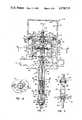
- FIG. 1is a longitudinal central section view of the additive injection pump apparatus of the present invention
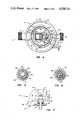
- FIG. 2is a detail section view taken along the line 2--2 of FIG. 1;
- FIG. 3is a detail section view taken along the line 3--3 of FIG. 1;
- FIG. 4is a section view taken along the line 4--4 of FIG. 1;
- FIG. 5is a section view taken along the line 5--5 of FIG. 1;
- FIG. 6is a section view taken along the line 6--6 of FIG. 1;
- FIG. 7is a detail section view taken along the line 7--7 of FIG. 4;
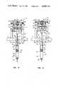
- FIGS. 8 through 11are views of the apparatus in schematic form showing the positions of the respective parts of the apparatus as the motor and injection pump pistons move through an operating cycle.
- the improved liquid additive injection pump apparatusis generally designated by the numeral 12 and comprises a housing 14 having a lower section 16 and an upper section 18.
- the housing section 16includes opposed bosses 19 and 20 providing respective fluid inlet and discharge passages 21 and 22.
- the bosses 19 and 20are adapted to be connected to a conduit, not shown, for conducting a primary liquid flow stream, such as water, into which a fluid additive is to be injected to flow with the liquid leaving the passage 22 and being conducted to an end use.
- the housing 16includes an interior cylindrical wall part 24 delimited by a cylindrical bore 26 forming a first expansible chamber 28 for a reciprocable piston assembly 30.
- the housing 18is releasably clamped to the housing 16 across cooperating circumferential flanges 32 and 34, respectively, which are suitably secured together with a conventional cylindrical band clamp 36.
- the housing 18includes a cylindrical bore 38 which is cooperable with the piston assembly 30 to form a second expansible chamber 40.
- the housing section 16further includes a third expansible fluid discharge chamber 42 which is defined in part between the wall part 24 and an outer cylindrical sidewall 25.
- the chamber 42is in communication with the fluid discharge passage 22 and the chamber 28 is in communication with the fluid inlet passage 21.
- the housing section 16further includes a bottom wall portion 44 integrally formed with the sidewall 25 and having a threaded bore 46 coaxial with the bore 26 for threaded engagement with one end of an elongated tubular additive injection pump cylinder 48.
- the housing part 16still further includes an interior cylindrical boss 50 having a stepped bore 52 formed therein and through which a pump piston rod 54 projects and is in slidable sealing engagement with a conventional piston rod seal 56.
- the rod seal 56is suitably retained in the bore 52 by a removable plug member 58.
- the piston assembly 30includes a first piston part 31 which is reciprocably disposed in the bore 26 and is in sealing engagement therewith at a suitable piston ring seal 60.
- the piston assembly 30includes a second piston part 33 of larger diameter than the piston part 31 and suitably secured thereto and slidably disposed in the chamber 40.
- the piston part 33is in slidable sealing engagement with the bore 38 by a suitable piston ring seal 62. Accordingly, the axially projected area of piston face 35 with respect to a longitudinal central axis 17 and exposed to the chamber 40 is greater than the opposed axially projected area of piston face 37 which is exposed to chamber 28.
- the differential areas between the effective piston faces 35 and 37are important to the functioning of the motor utilizing the piston assembly 30.
- a bottom wall 39 of the piston part 31is suitably secured to the upper end of piston rod 54 by a threaded fastener 64.
- the bottom wall 39includes an opening 66 therein which communicates the chamber 28 with an interior chamber portion 68 of the first chamber 28 formed within the piston assembly 30.
- the piston part 33includes a central bore 70 which is cooperable with a movable valve closure member 72 to place the chambers 28 and 40 in communication with each other and to effectively block the flow of fluid between the chambers 28 and 40.
- the closure member 72comprises a generally cylindrical plug having a central longitudinal bore 74 formed therein and having a resilient seating member 76 engageable with the piston part 33 to block communication between the chambers 28 and 40 through the bore 70.
- the closure member 72is movable in a generally downward direction, viewing FIG. 1, to place the chambers 28 and 40 in communication with each other through plural longitudinal grooves 80, see FIG. 2 also, formed in a reduced diameter portion of the closure member.
- the closure member 72is adapted to be biased in the position shown or in an open position to be shown and described further herein in conjunction with FIGS. 9 and 10 by a leaf spring 82 which is secured to the closure member 72 and is engaged with an axially projecting flange portion 83 of the piston part 33.
- the piston part 33further includes at least two fluid discharge valve passages 86 formed near the outer periphery of the part 33 and in communication with the chamber 42.
- Poppet type valve closure members 88are disposed for closing the passages 86 and are supported on opposed radially projecting arms 90 of a support member 92 which is suitably secured on the closure member 72 in a peripheral groove 93, FIG. 2. Accordingly, when the closure member 72 moves to a position such as shown in FIGS. 9 and 10 to place the chambers 28 and 40 in communication with each other the valve closure members 88 move to block flow of fluid between the chambers 40 and 42.
- the support arms 90are somewhat resiliently deflectable to provide for suitable seating of the closure members 88 against the piston part 33 to close the passages 86.
- valve members 72 and 88are assisted in their movement between respective open and closed positions by a mechanism comprising an elongated cylindrical shaft 100 having a portion 102 slidably disposed in the bore 78 and having a transverse collar portion 104 formed on its upper distal end, FIG. 1.
- the shaft 100includes an enlarged diameter portion 106 forming a transverse shoulder 107 with the portion 102 and having an elongated slot 108 formed therein.
- the lower end of the shaft 100includes a yoke section forming opposed axially extending arms 109 which project through slots 110 formed in the piston bottom wall 39 on opposite sides of the upper end of piston rod 54.
- the shaft 100is biased in opposed limit positions by a toggle type biasing mechanism including a lost motion coupling formed by a pin 112, FIGS. 3 and 4, disposed in the slot 108 and secured at its opposite ends to opposed links 114 and 116, respectively.
- the links 114 and 116are suitably retained on the pin 112 and are pivotal relative to the pin.
- the opposite ends of the links 114are connected to a pin 118 disposed in an elongated slot 120 formed in a boss 122 on the piston part 31.
- the links 116are suitably secured to a second pin 118 disposed in an elongated slot 121 formed in a boss 123 virtually identical to the boss 120 and directly opposite the boss 120 as shown in FIG. 4.
- the pins 118are secured to a pair of extension coil springs 126 which yieldably bias the pins toward each other to the limit position shown in FIG. 4 in the slots 120 and 121.
- the links 114 and 116are operable to extend the pins 118 in the slots 120 and 121 through the centered position of the links shown in FIG. 8 to the position shown in FIG. 9 to snap the closure member 72 into an open position and the closure members 88 into a closed position.
- the distal ends 111 of the arms 109are engageable with the boss 50, as shown in FIG.
- valve biasing mechanismto move the links 114 and 116 through a centered position to snap the closure member 72 in a closed position and the closure members 88 into an open position, as illustrated in FIG. 1.
- the liquid injection pump cylinder 48is closed at its lower end by a removable cap 130 which includes a fitting 132 forming a liquid additive inlet passage 134.
- the cap 130is threadedly connected to the lower end of the cylinder 48 and also is provided with a ball type check valve 136 which is operable to engage a seat 138 to prevent flow of fluid out of an interior chamber 140 through the passage 134.
- the check valve 136is suitably retained for limited movement away from seat 138 by opposed retainer fingers 141.
- the piston rod 54extends substantially through the chamber 140 in the position of the piston assembly 30 illustrated in FIG. 1 and includes a lower transverse flange 144 supporting a circumferential seal member 146 which may be a conventional o-ring or the like.
- the pump cylinder 48includes a longitudinal bore 49 defining, in part, the chamber 140 and slidably supporting therein an additive injection pump piston 150.
- the piston 150is slidably journalled on the rod 54 and includes a plurality of longitudinal passages 152 formed therein and communicating the chamber 140 with a chamber portion 156 formed in the cylinder 48 between the piston 150 and the seal 56.
- a lower transverse end face 153 of piston 150is engageable with the seal ring 146, however, to close off communication of fluid between the chambers 140 and 156 through the passages 152.
- the piston 150is supported in the bore 149 by suitable piston ring seals 157 disposed in cooperating circumferential grooves formed in the piston 150 in a conventional manner.
- the lower end of the piston rod 54includes a separable rod section 55 which is secured to an upper rod section 57 by a transversely extending retaining pin 158, FIG. 6, which extends through cooperating transverse bores formed in the rod sections 55 and 57, respectively, to join the rod sections together.
- the pin 158may be suitably retained in the position shown in FIG. 6 by a resilient retaining collar 160 which is removable to permit extraction of the pin 158 whereby the rod section 55 may be separated from the rod section 57.
- the collar 160also forms a retainer for a plurality of circumferential additive pump displacement control washers 162, 164, and 166, as shown by way of example in FIG.
- the washers 162, 164 and 166are preselected in accordance with the predetermined quantity of liquid to be injected per stroke of the additive injection apparatus and placed over the rod section 55 for retention between the piston 150 and the collar 160.
- the washers 162, 164 and 166are of smaller diameter than the bore 49 and are loosely retained on the piston rod 54 to permit free flow of additive fluid therearound.
- a fluid additive substancemay be injected into the primary fluid flowing through the apparatus 12 by injection of the additive fluid into the passage 22 downstream of the motor formed, in part, by the piston assembly 30 so that the additive will not be exposed to the piston assembly, its seals, the valves 72 and 88 or the valve actuating mechanism described hereinabove.
- the housing section 16is provided with a passage 164 formed by a conduit 166 extending from communication with the chamber 156 into the passage 22 whereby displacement of fluid from the chamber 156 by the piston 150 results in injection of fluid into the passage 22 to mix with the primary fluid after it has passed substantially through the apparatus 12.
- the apparatus 12also includes a bypass valve for bypassing the primary fluid which would normally flow through the apparatus 12 directly from the chamber 28 to the passage 22 without actuating the motor piston assembly 30.
- a conventional tapered plug valve closure member 170is suitably supported in a tapered valve bore 172 formed in the housing 16 and interposed in a passage 174 which extends between the chamber 28 and the passage 22 as indicated in FIGS. 4 and 7.
- the closure plug 170is suitably retained in the bore 172 by a removable retaining nut 176.
- primary fluidmay flow directly from chamber 28 through passage 174 and a suitable passage 171 formed in the closure plug directly to the passage 22.
- the plug 170may be rotated approximately 90° from the position shown in FIG. 7 to block the flow of fluid from chamber 28 directly to passage 22 by way of passage 174.
- FIGS. 1 and 8in particular, in the position of the piston assembly 30 and the piston 150 illustrated in FIG. 1, it will be assumed that primary fluid under pressure is present in chambers 28 and 68 from a source, not shown, by way of passage 21 and that the bypass valve closure member is closed to block the passage 174. It will further be assumed that primary fluid at a reduced pressure is present in chambers 40, 42 and passage 22 and, since the valves 88 are in an open position the pressure is the same in these respective chambers.
- passage 134is in communication with a source of fluid additive, not shown, and that a quantity of additive has been drawn into chamber 140 as the result of a previous operating cycle of the piston 150 and the piston rod 54. Due to the higher pressure of fluid in the chambers 28 and 68 than the fluid pressure in chambers 40 and 42 the piston assembly 30 is being urged to move upwardly due to a pressure fluid force acting across the effective area defined by the piston face 37.
- valve closure member 72In the position shown in FIG. 8, the valve closure member 72 is still in a position to block flow of fluid from chambers 28 and 68 to chamber 40 although fluid in chamber 40 flows through passages 86 into chamber 42. Since the volume of the chamber 42 does not increase at the same rate as decrease in the volume of chamber 40 some displacement of primary fluid occurs from chamber 42 through passage 29 and passage 22 to mix with the additive being injected into passage 22 during the upward stroke movement of the piston assembly 30 and the piston 150.
- valve closure member 72remains in the open position and the valve actuating mechanism comprising links 114 and 116 and pin 112 remains in the position into which it was displaced during movement to the FIG. 9 position from the FIG. 8 position.
- the piston 150 and the washers 162, 164 and 166remain in the FIG. 9 position even though the piston rod 54 is moving downward, thanks to frictional engagement of the piston ring seals 157 with the bore wall 149.
- the piston 150 and the washers supported thereonremain in the FIG. 9 position until the collar 160 engages the assembly of the washers 162, 164 and 166 and the piston 150 whereupon further downward movement of the rod 54 will displace the assembly with the rod 54.
- the check valve 136is normally in a closed position.
- the closure member 72is assisted in its movement and biased into the closed position.
- movement of the closure member 72 to close off the passage 70results in opening of the valves 88 to permit flow of fluid from chamber 40 to chamber 42.
- the piston assembly 30commences an upstroke described previously; however, displacement of a predetermined quantity of additive does not occur until the seal 146 engages the bottom face 153 of piston 150 to close off communication between chambers 140 and 156.
- the abovedescribed operating cycle of the apparatus 12occurs with relatively great speed depending on the working pressure of the primary fluid flowing into the chamber 28 and the downstream pressure of the fluid in passage 22.
- a corresponding predetermined quantity of fluid additiveis injected from the chamber 156 into the passage 22.
- the amount of fluid additive injected per stroke cycle of the piston assembly 30is preselected by the overall height of the washer stack comprising the washers 162, 164 and 166.
- additional washersmay be interposed between the piston 150 and the collar 160 or, one or more of the washers shown by way of example may be removed from the piston rod 54.
- some relative displacement between the rod 54 and the piston 150must be maintained to permit transfer of additive fluid from the chamber 140 to the chamber 156 through the passages 152.
- the number of washers retained on the piston rod 54may be conveniently changed by unthreading the cylinder 48 at its connection with the housing 16, removing the collar 160 and the pin 158 to separate the rod section 55 from the rod section 57 whereby washers may be added to or removed from the rod section 55 at will.
- the rod section 55is then reassembled with the rod section 57 and the cylinder 48 replaced.
- the primary fluid flow to the apparatus 12is preferably shut off during the modification of the displacement of the liquid additive injection apparatus.
- the arrangement of the piston assembly 30, piston rod 54 and liquid additive pump piston 150is such that all working forces acting on these parts of the apparatus 12 are directed generally along the center line or central axis 17 and there is no tendency to cock or skew the piston assembly 30, the rod 54 or the piston 150. This reduces wear and degradation of the seals 56, 60, 62 and 157 and provides for proper seating of the closure members 72 and 88. Still further, those skilled in the art will appreciate that the mechanism for snapping the valve closure member 72 into the open and closed positions provides for positive and reliable operation of the injection pump motor and the pump piston.
- the apparatus 12may be constructed of conventional engineering materials for liquid pumps which are compatible with substances being conveyed therethrough.
- the housing section 16may be cast of metal or plastic and in like manner the piston assembly 30 may be suitably formed of conventional engineering materials.
- the seals used throughout the apparatus 12may comprise conventional o-rings or piston ring type seals, or resilient lip type seals may be used for the seals 56, 60 and 62, for example.
Landscapes
- Engineering & Computer Science (AREA)
- Physics & Mathematics (AREA)
- General Physics & Mathematics (AREA)
- Automation & Control Theory (AREA)
- Power Engineering (AREA)
- Accessories For Mixers (AREA)
- Reciprocating Pumps (AREA)
Abstract
Description
Claims (19)
Priority Applications (10)
| Application Number | Priority Date | Filing Date | Title |
|---|---|---|---|
| US06/610,755US4558715A (en) | 1984-05-16 | 1984-05-16 | Apparatus for injecting measured quantities of liquid into a fluid stream |
| CA000480384ACA1266181A (en) | 1984-05-16 | 1985-04-30 | Apparatus for injecting measured quantities of liquid into a fluid stream |
| DE1985105513DE161614T1 (en) | 1984-05-16 | 1985-05-06 | APPARATUS FOR INJECTING MEASURED LIQUID AMOUNTS INTO THE FLOW OF A LIQUID MEDIUM. |
| DE8585105513TDE3580185D1 (en) | 1984-05-16 | 1985-05-06 | APPARATUS FOR INJECTING MEASURED LIQUID AMOUNTS INTO THE FLOW OF A LIQUID MEDIUM. |
| AT85105513TATE57775T1 (en) | 1984-05-16 | 1985-05-06 | APPARATUS FOR INJECTING MEASURED QUANTITIES OF LIQUID INTO A STREAM OF A LIQUID MEDIUM. |
| EP19850105513EP0161614B1 (en) | 1984-05-16 | 1985-05-06 | Apparatus for injecting measured quantities of liquid into a fluid stream |
| AU42083/85AAU570110B2 (en) | 1984-05-16 | 1985-05-08 | Injecting liquid into fluid stream |
| JP60101683AJPS6146479A (en) | 1984-05-16 | 1985-05-15 | Injection apparatus |
| NZ21208785ANZ212087A (en) | 1984-05-16 | 1985-05-15 | Injecting additive into fluid flow:injection pump driven by fluid flow |
| CA000611766ACA1306609C (en) | 1984-05-16 | 1989-09-18 | Apparatus for injecting measured quantities of liquid into a fluid stream |
Applications Claiming Priority (1)
| Application Number | Priority Date | Filing Date | Title |
|---|---|---|---|
| US06/610,755US4558715A (en) | 1984-05-16 | 1984-05-16 | Apparatus for injecting measured quantities of liquid into a fluid stream |
Related Child Applications (1)
| Application Number | Title | Priority Date | Filing Date |
|---|---|---|---|
| US69266885AContinuation-In-Part | 1984-05-16 | 1985-01-17 |
Publications (1)
| Publication Number | Publication Date |
|---|---|
| US4558715Atrue US4558715A (en) | 1985-12-17 |
Family
ID=24446294
Family Applications (1)
| Application Number | Title | Priority Date | Filing Date |
|---|---|---|---|
| US06/610,755Expired - LifetimeUS4558715A (en) | 1984-05-16 | 1984-05-16 | Apparatus for injecting measured quantities of liquid into a fluid stream |
Country Status (2)
| Country | Link |
|---|---|
| US (1) | US4558715A (en) |
| JP (1) | JPS6146479A (en) |
Cited By (67)
| Publication number | Priority date | Publication date | Assignee | Title |
|---|---|---|---|---|
| FR2602282A1 (en)* | 1986-07-31 | 1988-02-05 | Cloup Jean | IMPROVEMENT IN DEVICES FOR INJECTING AN ADDITIVE DOSE INTO A MAIN FLUID |
| US4809731A (en)* | 1985-01-17 | 1989-03-07 | Frank A. Walton | Liquid injection apparatus having an external adjustor |
| US4844700A (en)* | 1987-10-29 | 1989-07-04 | Henderson Charles J | Pressure amplifying pump system |
| US5002468A (en)* | 1987-05-28 | 1991-03-26 | Yamada Yuki Seizo Co., Ltd. | Switching device for reciprocating pumps |
| US5022585A (en)* | 1989-01-17 | 1991-06-11 | Automated Chemical Management, Inc. | Automatic chemigation |
| US5120202A (en)* | 1987-05-28 | 1992-06-09 | Yamada Yuki Seizo Co., Ltd. | Switching device for reciprocating pumps |
| US5137435A (en)* | 1991-03-25 | 1992-08-11 | Frank And Robyn Walton 1990 Family Trust | Compression spring fluid motor |
| US5184943A (en)* | 1991-03-08 | 1993-02-09 | Frank And Robyn Walton 1990 Family Trust | Rolling diaphragm injection pump |
| US5243897A (en)* | 1992-04-07 | 1993-09-14 | Frank & Robyn Walton 1990 Family Trust | Magnetically actuated fluid motor |
| US5314120A (en)* | 1989-02-16 | 1994-05-24 | Ciba-Geigy Corporation | Device for applying plant-protecting compositions |
| WO1996005428A1 (en)* | 1994-08-16 | 1996-02-22 | Frank And Robyn Walton 1990 Family Trust | Direct action fluid motor and injection pump |
| US5572922A (en)* | 1994-11-16 | 1996-11-12 | Daewoo Electronics Co., Ltd. | Actuating plunger of an electromagnetic pump |
| US5951265A (en)* | 1997-12-29 | 1999-09-14 | Diemold International, Inc. | Fluid driven reciprocating engine or pump having overcenter, snap-action mechanical valve control |
| EP1061426A2 (en) | 1999-06-06 | 2000-12-20 | Dosmatic USA, Inc. | Pumping system for the injection of measured qualities of fluid into a fluid stream |
| US6314979B1 (en) | 1999-03-16 | 2001-11-13 | Fertigator, Inc. | Liquid injection apparatus and method for horticultural watering systems |
| US6684753B1 (en) | 1999-02-09 | 2004-02-03 | Dosatron International | Reciprocating differential hydraulic machine, especially a differential hydraulic machine |
| US20040044527A1 (en)* | 2002-09-04 | 2004-03-04 | Microsoft Corporation | Quantization and inverse quantization for audio |
| US20040049978A1 (en)* | 2002-09-16 | 2004-03-18 | Lips Edwin A. | Combined controller apparatus for a horticultural watering system |
| US20040074921A1 (en)* | 2002-08-16 | 2004-04-22 | Lips Edwin A. | System for controlled dispersion of a consumable product |
| US6742761B2 (en)* | 2001-04-10 | 2004-06-01 | Tini Alloy Company | Miniature latching valve |
| US6752172B2 (en)* | 2000-10-27 | 2004-06-22 | Fresenius Medical Care Deutschland Gmbh | Disposable cassette having a sealing membrane and a valve actuator therefor |
| WO2005008060A2 (en) | 2003-07-08 | 2005-01-27 | Dosmatic Usa, Inc. | On/off switch for liquid additive injection pump |
| US20060204376A1 (en)* | 2005-03-09 | 2006-09-14 | Walton Frank A | Liquid additive injection pump with mixing chamber and one way valve |
| US7422403B1 (en) | 2003-10-23 | 2008-09-09 | Tini Alloy Company | Non-explosive releasable coupling device |
| US7441888B1 (en) | 2005-05-09 | 2008-10-28 | Tini Alloy Company | Eyeglass frame |
| US7540899B1 (en) | 2005-05-25 | 2009-06-02 | Tini Alloy Company | Shape memory alloy thin film, method of fabrication, and articles of manufacture |
| US7544257B2 (en) | 2004-05-06 | 2009-06-09 | Tini Alloy Company | Single crystal shape memory alloy devices and methods |
| US7586828B1 (en) | 2003-10-23 | 2009-09-08 | Tini Alloy Company | Magnetic data storage system |
| USD602512S1 (en) | 2008-10-24 | 2009-10-20 | Dosmatic Usa, Inc. | Piston assembly |
| USD603427S1 (en) | 2008-09-15 | 2009-11-03 | Dosmatic Usa, Inc. | On-off plunger |
| USD603435S1 (en) | 2008-08-29 | 2009-11-03 | Dosmatic Usa, Inc. | Dosage piston retention clip |
| US20100051716A1 (en)* | 2008-09-03 | 2010-03-04 | Walton Frank A | Automated switch for liquid additive injection pump |
| US7763342B2 (en) | 2005-03-31 | 2010-07-27 | Tini Alloy Company | Tear-resistant thin film methods of fabrication |
| US20100282072A1 (en)* | 2006-01-13 | 2010-11-11 | Dosatron International | Hydraulic machine, in particular hydraulic motor, with a reciprocating movement |
| US7842143B2 (en) | 2007-12-03 | 2010-11-30 | Tini Alloy Company | Hyperelastic shape setting devices and fabrication methods |
| US20110015610A1 (en)* | 2009-07-15 | 2011-01-20 | Fresenius Medical Care Holdings, Inc. | Medical fluid cassettes and related systems and methods |
| US7901376B2 (en) | 2007-07-05 | 2011-03-08 | Baxter International Inc. | Dialysis cassette having multiple outlet valve |
| US20110077784A1 (en)* | 2009-09-29 | 2011-03-31 | Jon Lips | System and method for injecting a fluid additive into a fluid dispensation system |
| US20110163172A1 (en)* | 2010-01-06 | 2011-07-07 | Puricore, Inc. | Method of injecting solution into a misting line |
| US8007674B2 (en) | 2007-07-30 | 2011-08-30 | Tini Alloy Company | Method and devices for preventing restenosis in cardiovascular stents |
| US20110274563A1 (en)* | 2009-01-19 | 2011-11-10 | Tefen Manufacture & Marketing Plastic Products 1990 Ltd. | Dosing pump |
| US8142653B2 (en) | 2002-06-04 | 2012-03-27 | Fresenius Medical Care Deutschland Gmbh | Medical fluid cassettes and related systems |
| US8349099B1 (en) | 2006-12-01 | 2013-01-08 | Ormco Corporation | Method of alloying reactive components |
| US8382917B2 (en) | 2007-12-03 | 2013-02-26 | Ormco Corporation | Hyperelastic shape setting devices and fabrication methods |
| US8556969B2 (en) | 2007-11-30 | 2013-10-15 | Ormco Corporation | Biocompatible copper-based single-crystal shape memory alloys |
| US8584767B2 (en) | 2007-01-25 | 2013-11-19 | Tini Alloy Company | Sprinkler valve with active actuation |
| US8684101B2 (en) | 2007-01-25 | 2014-04-01 | Tini Alloy Company | Frangible shape memory alloy fire sprinkler valve actuator |
| USD708293S1 (en) | 2013-03-11 | 2014-07-01 | Oms Investments, Inc. | Spraying device |
| US8932032B2 (en) | 2005-07-13 | 2015-01-13 | Fresenius Medical Care Holdings, Inc. | Diaphragm pump and pumping systems |
| US8986254B2 (en) | 2009-03-20 | 2015-03-24 | Fresenius Medical Care Holdings, Inc. | Medical fluid pump systems and related components and methods |
| US9011114B2 (en) | 2011-03-09 | 2015-04-21 | Fresenius Medical Care Holdings, Inc. | Medical fluid delivery sets and related systems and methods |
| US9079142B2 (en) | 2013-03-11 | 2015-07-14 | Oms Investments, Inc. | Hydraulic mixing device for sprayer system |
| US9180240B2 (en) | 2011-04-21 | 2015-11-10 | Fresenius Medical Care Holdings, Inc. | Medical fluid pumping systems and related devices and methods |
| US9500188B2 (en) | 2012-06-11 | 2016-11-22 | Fresenius Medical Care Holdings, Inc. | Medical fluid cassettes and related systems and methods |
| US9561323B2 (en) | 2013-03-14 | 2017-02-07 | Fresenius Medical Care Holdings, Inc. | Medical fluid cassette leak detection methods and devices |
| US9610392B2 (en) | 2012-06-08 | 2017-04-04 | Fresenius Medical Care Holdings, Inc. | Medical fluid cassettes and related systems and methods |
| US9694125B2 (en) | 2010-12-20 | 2017-07-04 | Fresenius Medical Care Holdings, Inc. | Medical fluid cassettes and related systems and methods |
| US10117985B2 (en) | 2013-08-21 | 2018-11-06 | Fresenius Medical Care Holdings, Inc. | Determining a volume of medical fluid pumped into or out of a medical fluid cassette |
| US10124197B2 (en) | 2012-08-31 | 2018-11-13 | TiNi Allot Company | Fire sprinkler valve actuator |
| WO2019007972A1 (en)* | 2017-07-03 | 2019-01-10 | Henkel Ag & Co. Kgaa | PNEUMATIC MOTOR WITH ACTIVE HUB CONTROL |
| WO2020014254A1 (en)* | 2018-07-11 | 2020-01-16 | Superior Energy Services, Llc | Autonomous flow controller device |
| CN111622941A (en)* | 2020-03-03 | 2020-09-04 | 江苏大学 | Valve adjusting type proportional fertilization pump |
| US11040230B2 (en) | 2012-08-31 | 2021-06-22 | Tini Alloy Company | Fire sprinkler valve actuator |
| GB2593774A (en)* | 2020-04-03 | 2021-10-06 | Hydro Systems Europe Ltd | Liquid dispenser comprising piezoelectric detector |
| US20220349492A1 (en)* | 2021-04-30 | 2022-11-03 | Abb Schweiz Ag | Positioner Drive for Controlling a Valve Positioner with Pneumatic Output |
| IT202300003831A1 (en)* | 2023-03-02 | 2024-09-02 | Mixtron S R L | PROPORTIONAL VOLUMETRIC DOSER |
| US12378954B2 (en) | 2022-10-03 | 2025-08-05 | Saudi Arabian Oil Company | Process pumps and related methods of treating a process line |
Families Citing this family (2)
| Publication number | Priority date | Publication date | Assignee | Title |
|---|---|---|---|---|
| JPH0781549B2 (en)* | 1987-05-28 | 1995-08-30 | 山田油機製造株式会社 | Reciprocating motion switching device for pump |
| JPH04122471U (en)* | 1991-03-22 | 1992-11-04 | いすゞ自動車株式会社 | Integrated oil seal fitting |
Citations (10)
| Publication number | Priority date | Publication date | Assignee | Title |
|---|---|---|---|---|
| US1506834A (en)* | 1924-02-14 | 1924-09-02 | Hook Charles Howard | Control valve |
| US1674614A (en)* | 1925-07-13 | 1928-06-19 | Zim Mfg Company | Pump for automobile oiling systems |
| US2262031A (en)* | 1940-05-06 | 1941-11-11 | George L N Meyer | Fluid proportioning device |
| GB595458A (en)* | 1944-12-08 | 1947-12-05 | Uni Gun Lubricating Equipment | Improvements in or relating to reciprocating pumps |
| US2712427A (en)* | 1952-07-22 | 1955-07-05 | Arthur A Welbom | Impact type snap acting shut-off valve |
| US3213873A (en)* | 1961-05-23 | 1965-10-26 | Carl F Jensen | Self-powered fluid treater |
| US3665808A (en)* | 1970-10-07 | 1972-05-30 | Walter H Vestal | Pumping system for liquid hydrocarbons and the like |
| US3692274A (en)* | 1971-05-17 | 1972-09-19 | Nordson Corp | Valve for pneumatic motor |
| US3901313A (en)* | 1973-08-13 | 1975-08-26 | Thaddeus M Doniguian | Oil well treatment |
| US3937241A (en)* | 1973-11-29 | 1976-02-10 | Philippe Cloup | Device for injecting an adjuvant into a liquid |
Family Cites Families (2)
| Publication number | Priority date | Publication date | Assignee | Title |
|---|---|---|---|---|
| JPS5122105A (en)* | 1974-08-19 | 1976-02-21 | Tokico Ltd | HONPUSOCHI |
| JPS591352B2 (en)* | 1975-10-16 | 1984-01-11 | カブシキガイシヤ マルヤマセイサクシヨ | Chiyuuniyu pump |
- 1984
- 1984-05-16USUS06/610,755patent/US4558715A/ennot_activeExpired - Lifetime
- 1985
- 1985-05-15JPJP60101683Apatent/JPS6146479A/enactivePending
Patent Citations (10)
| Publication number | Priority date | Publication date | Assignee | Title |
|---|---|---|---|---|
| US1506834A (en)* | 1924-02-14 | 1924-09-02 | Hook Charles Howard | Control valve |
| US1674614A (en)* | 1925-07-13 | 1928-06-19 | Zim Mfg Company | Pump for automobile oiling systems |
| US2262031A (en)* | 1940-05-06 | 1941-11-11 | George L N Meyer | Fluid proportioning device |
| GB595458A (en)* | 1944-12-08 | 1947-12-05 | Uni Gun Lubricating Equipment | Improvements in or relating to reciprocating pumps |
| US2712427A (en)* | 1952-07-22 | 1955-07-05 | Arthur A Welbom | Impact type snap acting shut-off valve |
| US3213873A (en)* | 1961-05-23 | 1965-10-26 | Carl F Jensen | Self-powered fluid treater |
| US3665808A (en)* | 1970-10-07 | 1972-05-30 | Walter H Vestal | Pumping system for liquid hydrocarbons and the like |
| US3692274A (en)* | 1971-05-17 | 1972-09-19 | Nordson Corp | Valve for pneumatic motor |
| US3901313A (en)* | 1973-08-13 | 1975-08-26 | Thaddeus M Doniguian | Oil well treatment |
| US3937241A (en)* | 1973-11-29 | 1976-02-10 | Philippe Cloup | Device for injecting an adjuvant into a liquid |
Cited By (114)
| Publication number | Priority date | Publication date | Assignee | Title |
|---|---|---|---|---|
| US4809731A (en)* | 1985-01-17 | 1989-03-07 | Frank A. Walton | Liquid injection apparatus having an external adjustor |
| FR2602282A1 (en)* | 1986-07-31 | 1988-02-05 | Cloup Jean | IMPROVEMENT IN DEVICES FOR INJECTING AN ADDITIVE DOSE INTO A MAIN FLUID |
| EP0255791A1 (en)* | 1986-07-31 | 1988-02-10 | Jean Cloup | Device for injecting an additional product into a principal fluid |
| US4756329A (en)* | 1986-07-31 | 1988-07-12 | Jean Cloup | Devices for the injection of an additive product metered into a main fluid |
| US5002468A (en)* | 1987-05-28 | 1991-03-26 | Yamada Yuki Seizo Co., Ltd. | Switching device for reciprocating pumps |
| US5120202A (en)* | 1987-05-28 | 1992-06-09 | Yamada Yuki Seizo Co., Ltd. | Switching device for reciprocating pumps |
| US4844700A (en)* | 1987-10-29 | 1989-07-04 | Henderson Charles J | Pressure amplifying pump system |
| US5022585A (en)* | 1989-01-17 | 1991-06-11 | Automated Chemical Management, Inc. | Automatic chemigation |
| US5314120A (en)* | 1989-02-16 | 1994-05-24 | Ciba-Geigy Corporation | Device for applying plant-protecting compositions |
| US5184943A (en)* | 1991-03-08 | 1993-02-09 | Frank And Robyn Walton 1990 Family Trust | Rolling diaphragm injection pump |
| EP0507071A1 (en)* | 1991-03-25 | 1992-10-07 | Frank And Robyn Walton 1990 Family Trust | Compression spring fluid motor |
| US5137435A (en)* | 1991-03-25 | 1992-08-11 | Frank And Robyn Walton 1990 Family Trust | Compression spring fluid motor |
| US5243897A (en)* | 1992-04-07 | 1993-09-14 | Frank & Robyn Walton 1990 Family Trust | Magnetically actuated fluid motor |
| WO1996005428A1 (en)* | 1994-08-16 | 1996-02-22 | Frank And Robyn Walton 1990 Family Trust | Direct action fluid motor and injection pump |
| US5513963A (en)* | 1994-08-16 | 1996-05-07 | Frank And Robyn Walton 1990 Family Trust | Direct action fluid motor and injection pump |
| US5572922A (en)* | 1994-11-16 | 1996-11-12 | Daewoo Electronics Co., Ltd. | Actuating plunger of an electromagnetic pump |
| US5951265A (en)* | 1997-12-29 | 1999-09-14 | Diemold International, Inc. | Fluid driven reciprocating engine or pump having overcenter, snap-action mechanical valve control |
| US6684753B1 (en) | 1999-02-09 | 2004-02-03 | Dosatron International | Reciprocating differential hydraulic machine, especially a differential hydraulic machine |
| US6314979B1 (en) | 1999-03-16 | 2001-11-13 | Fertigator, Inc. | Liquid injection apparatus and method for horticultural watering systems |
| EP1061426A3 (en)* | 1999-06-06 | 2002-07-10 | Dosmatic USA, Inc. | Pumping system for the injection of measured qualities of fluid into a fluid stream |
| EP1061426A2 (en) | 1999-06-06 | 2000-12-20 | Dosmatic USA, Inc. | Pumping system for the injection of measured qualities of fluid into a fluid stream |
| US6752172B2 (en)* | 2000-10-27 | 2004-06-22 | Fresenius Medical Care Deutschland Gmbh | Disposable cassette having a sealing membrane and a valve actuator therefor |
| US6742761B2 (en)* | 2001-04-10 | 2004-06-01 | Tini Alloy Company | Miniature latching valve |
| US8377293B2 (en) | 2002-06-04 | 2013-02-19 | Fresenius Medical Care Deutschland Gmbh | Dialysis fluid cassettes and related systems and methods |
| US10471194B2 (en) | 2002-06-04 | 2019-11-12 | Fresenius Medical Care Deutschland Gmbh | Dialysis systems and related methods |
| US9827359B2 (en) | 2002-06-04 | 2017-11-28 | Fresenius Medical Care Deutschland Gmbh | Dialysis systems and related methods |
| US8142653B2 (en) | 2002-06-04 | 2012-03-27 | Fresenius Medical Care Deutschland Gmbh | Medical fluid cassettes and related systems |
| US8366921B2 (en) | 2002-06-04 | 2013-02-05 | Fresenius Medical Care Deutschland Gmbh | Dialysis systems and related methods |
| US8721883B2 (en) | 2002-06-04 | 2014-05-13 | Fresenius Medical Care Deutschland Gmbh | Medical fluid cassettes and related systems |
| US8926835B2 (en) | 2002-06-04 | 2015-01-06 | Fresenius Medical Care Deustschland Gmbh | Dialysis systems and related methods |
| US9101709B2 (en) | 2002-06-04 | 2015-08-11 | Fresenius Medical Care Deutschland Gmbh | Dialysis fluid cassettes and related systems and methods |
| US8435408B2 (en) | 2002-06-04 | 2013-05-07 | Fresenius Medical Care Deutschland Gmbh | Medical fluid cassettes and related systems |
| US20040074921A1 (en)* | 2002-08-16 | 2004-04-22 | Lips Edwin A. | System for controlled dispersion of a consumable product |
| US20040044527A1 (en)* | 2002-09-04 | 2004-03-04 | Microsoft Corporation | Quantization and inverse quantization for audio |
| US20040049978A1 (en)* | 2002-09-16 | 2004-03-18 | Lips Edwin A. | Combined controller apparatus for a horticultural watering system |
| EP1658442A4 (en)* | 2003-07-08 | 2010-08-25 | Dosmatic Usa Inc | On/off switch for liquid additive injection pump |
| WO2005008060A2 (en) | 2003-07-08 | 2005-01-27 | Dosmatic Usa, Inc. | On/off switch for liquid additive injection pump |
| US7586828B1 (en) | 2003-10-23 | 2009-09-08 | Tini Alloy Company | Magnetic data storage system |
| US7422403B1 (en) | 2003-10-23 | 2008-09-09 | Tini Alloy Company | Non-explosive releasable coupling device |
| US7544257B2 (en) | 2004-05-06 | 2009-06-09 | Tini Alloy Company | Single crystal shape memory alloy devices and methods |
| US7632361B2 (en) | 2004-05-06 | 2009-12-15 | Tini Alloy Company | Single crystal shape memory alloy devices and methods |
| US7438537B2 (en) | 2005-03-09 | 2008-10-21 | Dosmatic Usa, Inc. | Liquid additive injection pump with mixing chamber and one way valve |
| US20060204376A1 (en)* | 2005-03-09 | 2006-09-14 | Walton Frank A | Liquid additive injection pump with mixing chamber and one way valve |
| US7763342B2 (en) | 2005-03-31 | 2010-07-27 | Tini Alloy Company | Tear-resistant thin film methods of fabrication |
| US7441888B1 (en) | 2005-05-09 | 2008-10-28 | Tini Alloy Company | Eyeglass frame |
| US7540899B1 (en) | 2005-05-25 | 2009-06-02 | Tini Alloy Company | Shape memory alloy thin film, method of fabrication, and articles of manufacture |
| US12392335B2 (en) | 2005-07-13 | 2025-08-19 | Baxter International Inc. | Medical fluid pumping system having backflow prevention |
| US10590924B2 (en) | 2005-07-13 | 2020-03-17 | Baxter International Inc. | Medical fluid pumping system including pump and machine chassis mounting regime |
| US8932032B2 (en) | 2005-07-13 | 2015-01-13 | Fresenius Medical Care Holdings, Inc. | Diaphragm pump and pumping systems |
| US10670005B2 (en) | 2005-07-13 | 2020-06-02 | Baxter International Inc. | Diaphragm pumps and pumping systems |
| US10578098B2 (en) | 2005-07-13 | 2020-03-03 | Baxter International Inc. | Medical fluid delivery device actuated via motive fluid |
| US11384748B2 (en) | 2005-07-13 | 2022-07-12 | Baxter International Inc. | Blood treatment system having pulsatile blood intake |
| US20100282072A1 (en)* | 2006-01-13 | 2010-11-11 | Dosatron International | Hydraulic machine, in particular hydraulic motor, with a reciprocating movement |
| US7975597B2 (en)* | 2006-01-13 | 2011-07-12 | Dosatron International | Hydraulic machine, in particular hydraulic motor, with a reciprocating movement |
| US8349099B1 (en) | 2006-12-01 | 2013-01-08 | Ormco Corporation | Method of alloying reactive components |
| US9340858B2 (en) | 2006-12-01 | 2016-05-17 | Ormco Corporation | Method of alloying reactive components |
| US10190199B2 (en) | 2006-12-01 | 2019-01-29 | Ormco Corporation | Method of alloying reactive components |
| US8685183B1 (en) | 2006-12-01 | 2014-04-01 | Ormco Corporation | Method of alloying reactive components |
| US8584767B2 (en) | 2007-01-25 | 2013-11-19 | Tini Alloy Company | Sprinkler valve with active actuation |
| US8684101B2 (en) | 2007-01-25 | 2014-04-01 | Tini Alloy Company | Frangible shape memory alloy fire sprinkler valve actuator |
| US7901376B2 (en) | 2007-07-05 | 2011-03-08 | Baxter International Inc. | Dialysis cassette having multiple outlet valve |
| US8007674B2 (en) | 2007-07-30 | 2011-08-30 | Tini Alloy Company | Method and devices for preventing restenosis in cardiovascular stents |
| US10610620B2 (en) | 2007-07-30 | 2020-04-07 | Monarch Biosciences, Inc. | Method and devices for preventing restenosis in cardiovascular stents |
| US8556969B2 (en) | 2007-11-30 | 2013-10-15 | Ormco Corporation | Biocompatible copper-based single-crystal shape memory alloys |
| US9539372B2 (en) | 2007-11-30 | 2017-01-10 | Ormco Corporation | Biocompatible copper-based single-crystal shape memory alloys |
| US7842143B2 (en) | 2007-12-03 | 2010-11-30 | Tini Alloy Company | Hyperelastic shape setting devices and fabrication methods |
| US8382917B2 (en) | 2007-12-03 | 2013-02-26 | Ormco Corporation | Hyperelastic shape setting devices and fabrication methods |
| US9127338B2 (en) | 2007-12-03 | 2015-09-08 | Ormco Corporation | Hyperelastic shape setting devices and fabrication methods |
| USD603435S1 (en) | 2008-08-29 | 2009-11-03 | Dosmatic Usa, Inc. | Dosage piston retention clip |
| US20100051716A1 (en)* | 2008-09-03 | 2010-03-04 | Walton Frank A | Automated switch for liquid additive injection pump |
| WO2010028124A3 (en)* | 2008-09-03 | 2010-05-27 | Dosmatic Usa, Inc. | Automated switch for liquid additive injection pump |
| USD603427S1 (en) | 2008-09-15 | 2009-11-03 | Dosmatic Usa, Inc. | On-off plunger |
| USD602512S1 (en) | 2008-10-24 | 2009-10-20 | Dosmatic Usa, Inc. | Piston assembly |
| US20110274563A1 (en)* | 2009-01-19 | 2011-11-10 | Tefen Manufacture & Marketing Plastic Products 1990 Ltd. | Dosing pump |
| US8986254B2 (en) | 2009-03-20 | 2015-03-24 | Fresenius Medical Care Holdings, Inc. | Medical fluid pump systems and related components and methods |
| US20110015610A1 (en)* | 2009-07-15 | 2011-01-20 | Fresenius Medical Care Holdings, Inc. | Medical fluid cassettes and related systems and methods |
| US9421314B2 (en) | 2009-07-15 | 2016-08-23 | Fresenius Medical Care Holdings, Inc. | Medical fluid cassettes and related systems and methods |
| US10507276B2 (en) | 2009-07-15 | 2019-12-17 | Fresenius Medical Care Holdings, Inc. | Medical fluid cassettes and related systems and methods |
| US20110077784A1 (en)* | 2009-09-29 | 2011-03-31 | Jon Lips | System and method for injecting a fluid additive into a fluid dispensation system |
| US8565925B2 (en) | 2009-09-29 | 2013-10-22 | Virid Services Llc | System and method for injecting a fluid additive into a fluid dispensation system |
| US20110163172A1 (en)* | 2010-01-06 | 2011-07-07 | Puricore, Inc. | Method of injecting solution into a misting line |
| US8628028B2 (en) | 2010-01-06 | 2014-01-14 | Puricore, Inc. | Method of injecting solution into a misting line |
| US9241498B2 (en) | 2010-01-06 | 2016-01-26 | Puricore, Inc. | Method of injecting solution into a misting line |
| US9694125B2 (en) | 2010-12-20 | 2017-07-04 | Fresenius Medical Care Holdings, Inc. | Medical fluid cassettes and related systems and methods |
| US9624915B2 (en) | 2011-03-09 | 2017-04-18 | Fresenius Medical Care Holdings, Inc. | Medical fluid delivery sets and related systems and methods |
| US9011114B2 (en) | 2011-03-09 | 2015-04-21 | Fresenius Medical Care Holdings, Inc. | Medical fluid delivery sets and related systems and methods |
| US10143791B2 (en) | 2011-04-21 | 2018-12-04 | Fresenius Medical Care Holdings, Inc. | Medical fluid pumping systems and related devices and methods |
| US9180240B2 (en) | 2011-04-21 | 2015-11-10 | Fresenius Medical Care Holdings, Inc. | Medical fluid pumping systems and related devices and methods |
| US11478578B2 (en) | 2012-06-08 | 2022-10-25 | Fresenius Medical Care Holdings, Inc. | Medical fluid cassettes and related systems and methods |
| US10463777B2 (en) | 2012-06-08 | 2019-11-05 | Fresenius Medical Care Holdings, Inc. | Medical fluid cassettes and related systems and methods |
| US9610392B2 (en) | 2012-06-08 | 2017-04-04 | Fresenius Medical Care Holdings, Inc. | Medical fluid cassettes and related systems and methods |
| US9500188B2 (en) | 2012-06-11 | 2016-11-22 | Fresenius Medical Care Holdings, Inc. | Medical fluid cassettes and related systems and methods |
| US11040230B2 (en) | 2012-08-31 | 2021-06-22 | Tini Alloy Company | Fire sprinkler valve actuator |
| US10124197B2 (en) | 2012-08-31 | 2018-11-13 | TiNi Allot Company | Fire sprinkler valve actuator |
| US9079142B2 (en) | 2013-03-11 | 2015-07-14 | Oms Investments, Inc. | Hydraulic mixing device for sprayer system |
| USD708293S1 (en) | 2013-03-11 | 2014-07-01 | Oms Investments, Inc. | Spraying device |
| US9561323B2 (en) | 2013-03-14 | 2017-02-07 | Fresenius Medical Care Holdings, Inc. | Medical fluid cassette leak detection methods and devices |
| US12061135B2 (en) | 2013-03-14 | 2024-08-13 | Fresenius Medical Care Holdings, Inc. | Medical fluid cassette leak detection methods and devices |
| US11262270B2 (en) | 2013-03-14 | 2022-03-01 | Fresenius Medical Care Holdings, Inc. | Medical fluid cassette leak detection methods and devices |
| US10539481B2 (en) | 2013-03-14 | 2020-01-21 | Fresenius Medical Care Holdings, Inc. | Medical fluid cassette leak detection methods and devices |
| US10117985B2 (en) | 2013-08-21 | 2018-11-06 | Fresenius Medical Care Holdings, Inc. | Determining a volume of medical fluid pumped into or out of a medical fluid cassette |
| US11291753B2 (en) | 2013-08-21 | 2022-04-05 | Fresenius Medical Care Holdings, Inc. | Determining a volume of medical fluid pumped into or out of a medical fluid cassette |
| WO2019007972A1 (en)* | 2017-07-03 | 2019-01-10 | Henkel Ag & Co. Kgaa | PNEUMATIC MOTOR WITH ACTIVE HUB CONTROL |
| WO2020014254A1 (en)* | 2018-07-11 | 2020-01-16 | Superior Energy Services, Llc | Autonomous flow controller device |
| US11047209B2 (en) | 2018-07-11 | 2021-06-29 | Superior Energy Services, Llc | Autonomous flow controller device |
| CN111622941B (en)* | 2020-03-03 | 2022-06-21 | 江苏大学 | A valve-regulated proportional fertilization pump |
| CN111622941A (en)* | 2020-03-03 | 2020-09-04 | 江苏大学 | Valve adjusting type proportional fertilization pump |
| US11773841B2 (en) | 2020-04-03 | 2023-10-03 | Hydro Systems Europe Ltd. | Liquid dispenser comprising piezoelectric detector |
| GB2593774A (en)* | 2020-04-03 | 2021-10-06 | Hydro Systems Europe Ltd | Liquid dispenser comprising piezoelectric detector |
| US12129844B2 (en) | 2020-04-03 | 2024-10-29 | Hydro Systems Europe Ltd. | Liquid dispenser comprising piezoelectric detector |
| US20220349492A1 (en)* | 2021-04-30 | 2022-11-03 | Abb Schweiz Ag | Positioner Drive for Controlling a Valve Positioner with Pneumatic Output |
| US12378954B2 (en) | 2022-10-03 | 2025-08-05 | Saudi Arabian Oil Company | Process pumps and related methods of treating a process line |
| IT202300003831A1 (en)* | 2023-03-02 | 2024-09-02 | Mixtron S R L | PROPORTIONAL VOLUMETRIC DOSER |
| WO2024180428A1 (en)* | 2023-03-02 | 2024-09-06 | Mixtron S.R.L. | Proportional volumetric dosing device |
Also Published As
| Publication number | Publication date |
|---|---|
| JPS6146479A (en) | 1986-03-06 |
Similar Documents
| Publication | Publication Date | Title |
|---|---|---|
| US4558715A (en) | Apparatus for injecting measured quantities of liquid into a fluid stream | |
| US4809731A (en) | Liquid injection apparatus having an external adjustor | |
| US5513963A (en) | Direct action fluid motor and injection pump | |
| US3930756A (en) | Metering pulse pump | |
| US5055008A (en) | Proportionating pump for liquid additive metering | |
| AU2016257652A1 (en) | Pneumatic timing valve | |
| US5234322A (en) | Proportioning pump improvements | |
| US4349130A (en) | Liquid metering pump | |
| US4161308A (en) | Switching valve assembly for fluid motor-driven injector pump | |
| EP0161614A2 (en) | Apparatus for injecting measured quantities of liquid into a fluid stream | |
| US4060351A (en) | Controlled inlet valves for metering pumps | |
| US4165759A (en) | Delivering measured quantities of liquid into a fluid | |
| US3010404A (en) | Chemical feed pump | |
| US4004602A (en) | Self-metering dual proportioner | |
| US4276001A (en) | Fluid pump assembly | |
| US6162027A (en) | Fluid driven pump and portioning check valve | |
| US5184943A (en) | Rolling diaphragm injection pump | |
| US3368458A (en) | Hydraulic motor | |
| US2559980A (en) | Pump | |
| US3329094A (en) | Switching valve | |
| US3291066A (en) | Pump apparatus with scavenger for check valve assembly | |
| US3131707A (en) | Proportioning medicator for waterers | |
| US3205830A (en) | Proportioning fluid pump | |
| US3213796A (en) | Variable proportioner | |
| RU2171398C1 (en) | Hydraulically-operated diaphragm proportioning pump |
Legal Events
| Date | Code | Title | Description |
|---|---|---|---|
| AS | Assignment | Owner name:KOWATACHI INTERNATIONAL LTD., 23 GREAT CASTLE ST., Free format text:ASSIGNMENT OF ASSIGNORS INTEREST.;ASSIGNORS:WALTON, FRANK A.;PERRINET, PAUL M.;REEL/FRAME:004284/0273 Effective date:19840515 Owner name:KOWATACHI INTERNATIONAL LTD., 23 GREAT CASTLE ST., Free format text:ASSIGNMENT OF ASSIGNORS INTEREST.;ASSIGNORS:WALTON, FRANK A.;PERRINET, PAUL M.;REEL/FRAME:004284/0271 Effective date:19840525 | |
| STCF | Information on status: patent grant | Free format text:PATENTED CASE | |
| AS | Assignment | Owner name:WALTON, FRANK A., 896 NORTH MILL STREET, LEWISVILL Free format text:NUNC PRO TUNC ASSIGNMENT;ASSIGNOR:KOWATACHI INTERNATIONAL LTD.;REEL/FRAME:004985/0354 Effective date:19880607 Owner name:WALTON, FRANK A., TEXAS Free format text:NUNC PRO TUNC ASSIGNMENT;ASSIGNOR:KOWATACHI INTERNATIONAL LTD.;REEL/FRAME:004985/0354 Effective date:19880607 | |
| FEPP | Fee payment procedure | Free format text:PAYOR NUMBER ASSIGNED (ORIGINAL EVENT CODE: ASPN); ENTITY STATUS OF PATENT OWNER: SMALL ENTITY | |
| FPAY | Fee payment | Year of fee payment:4 | |
| AS | Assignment | Owner name:AUTOTROL CORPORATION, 5730 NORTH GLEN PARK RD., MI Free format text:LICENSE;ASSIGNOR:J.F. EQUIPMENT CO. ("JFE"), A CORP. OF TX;REEL/FRAME:005584/0268 Effective date:19840720 | |
| FPAY | Fee payment | Year of fee payment:8 | |
| FPAY | Fee payment | Year of fee payment:12 | |
| AS | Assignment | Owner name:DOSMATIC, U.S.A., INC., TEXAS Free format text:ASSIGNMENT OF ASSIGNORS INTEREST;ASSIGNOR:WALTON, FRANK A.;REEL/FRAME:013077/0915 Effective date:20001220 |