US4558702A - Cardiac pacer having input/output circuit programmable for use with unipolar and bipolar pacer leads - Google Patents
Cardiac pacer having input/output circuit programmable for use with unipolar and bipolar pacer leadsDownload PDFInfo
- Publication number
- US4558702A US4558702AUS06/459,806US45980683AUS4558702AUS 4558702 AUS4558702 AUS 4558702AUS 45980683 AUS45980683 AUS 45980683AUS 4558702 AUS4558702 AUS 4558702A
- Authority
- US
- United States
- Prior art keywords
- atrial
- ventricular
- signal
- coupling
- pacer
- Prior art date
- Legal status (The legal status is an assumption and is not a legal conclusion. Google has not performed a legal analysis and makes no representation as to the accuracy of the status listed.)
- Expired - Lifetime
Links
- 102100026827Protein associated with UVRAG as autophagy enhancerHuman genes0.000titleclaimsabstractdescription75
- 101710102978Protein associated with UVRAG as autophagy enhancerProteins0.000titleclaimsabstractdescription75
- 230000000747cardiac effectEffects0.000titleclaimsabstractdescription27
- 230000002861ventricularEffects0.000claimsabstractdescription51
- 230000001746atrial effectEffects0.000claimsabstractdescription50
- 230000008878couplingEffects0.000claimsdescription22
- 238000010168coupling processMethods0.000claimsdescription22
- 238000005859coupling reactionMethods0.000claimsdescription22
- 239000003990capacitorSubstances0.000claimsdescription12
- 230000004044responseEffects0.000claimsdescription12
- 230000003750conditioning effectEffects0.000claims1
- 239000007943implantSubstances0.000abstractdescription4
- 230000009977dual effectEffects0.000abstractdescription2
- 230000001684chronic effectEffects0.000abstract1
- 238000010586diagramMethods0.000description6
- 238000010276constructionMethods0.000description5
- 230000001143conditioned effectEffects0.000description4
- 210000002837heart atriumAnatomy0.000description4
- 230000000638stimulationEffects0.000description4
- 230000008901benefitEffects0.000description3
- 230000028161membrane depolarizationEffects0.000description3
- 230000035945sensitivityEffects0.000description3
- 210000001124body fluidAnatomy0.000description2
- 239000010839body fluidSubstances0.000description2
- 230000003412degenerative effectEffects0.000description2
- 238000002955isolationMethods0.000description2
- 210000003205muscleAnatomy0.000description2
- 210000002976pectoralis muscleAnatomy0.000description2
- 206010065929Cardiovascular insufficiencyDiseases0.000description1
- 206010072064Exposure to body fluidDiseases0.000description1
- 230000003321amplificationEffects0.000description1
- 230000008859changeEffects0.000description1
- 238000004891communicationMethods0.000description1
- 238000007599dischargingMethods0.000description1
- 230000004064dysfunctionEffects0.000description1
- 230000036039immunityEffects0.000description1
- 238000002513implantationMethods0.000description1
- 230000005764inhibitory processEffects0.000description1
- 238000012977invasive surgical procedureMethods0.000description1
- 238000012986modificationMethods0.000description1
- 230000004048modificationEffects0.000description1
- 238000003199nucleic acid amplification methodMethods0.000description1
- 229920000136polysorbatePolymers0.000description1
- 229920006395saturated elastomerPolymers0.000description1
Images


Classifications
- A—HUMAN NECESSITIES
- A61—MEDICAL OR VETERINARY SCIENCE; HYGIENE
- A61N—ELECTROTHERAPY; MAGNETOTHERAPY; RADIATION THERAPY; ULTRASOUND THERAPY
- A61N1/00—Electrotherapy; Circuits therefor
- A61N1/18—Applying electric currents by contact electrodes
- A61N1/32—Applying electric currents by contact electrodes alternating or intermittent currents
- A61N1/36—Applying electric currents by contact electrodes alternating or intermittent currents for stimulation
- A61N1/362—Heart stimulators
- A61N1/365—Heart stimulators controlled by a physiological parameter, e.g. heart potential
- A61N1/368—Heart stimulators controlled by a physiological parameter, e.g. heart potential comprising more than one electrode co-operating with different heart regions
- Y—GENERAL TAGGING OF NEW TECHNOLOGICAL DEVELOPMENTS; GENERAL TAGGING OF CROSS-SECTIONAL TECHNOLOGIES SPANNING OVER SEVERAL SECTIONS OF THE IPC; TECHNICAL SUBJECTS COVERED BY FORMER USPC CROSS-REFERENCE ART COLLECTIONS [XRACs] AND DIGESTS
- Y10—TECHNICAL SUBJECTS COVERED BY FORMER USPC
- Y10S—TECHNICAL SUBJECTS COVERED BY FORMER USPC CROSS-REFERENCE ART COLLECTIONS [XRACs] AND DIGESTS
- Y10S128/00—Surgery
- Y10S128/902—Biological signal amplifier
Definitions
- the present inventionis directed generally to cardiac pacers, and more particularly to an input/output circuit for a cardiac pacer programmable for use with either bipolar or unipolar leads.
- Implantable battery operated cardiac pacersrequire one or more pacer leads for establishing electrical connection between their input/output terminals, and the atrium and/or the ventricle of the heart.
- pacer leadswhich are typically of the endocardial type for direct implantation in the heart, may be of either unipolar (UNIP) construction, wherein the implanted lead provides a cathode electrode and an anode electrode is provided through the pacer housing or other suitable means, or of bipolar (BIP) construction, wherein the implanted lead provides both the cathode and anode electrodes, and the pacer housing is isolated from the electrical circuit.
- unipolarunipolar
- BIPbipolar
- Unipolar leadshave the advantage of being physically smaller, and of providing less energy loss and greater sensitivity than bipolar leads.
- Bipolar leadshave the advantage of providing improved noise rejection, improved immunity against undesired muscle stimulation, and reduced susceptibility to artifacts resulting from patient movement.
- the choice of lead typeis made by the physician at the time of implant, depending on the particular pacing requirements of the patient and any problems encountered with either the sensing or pacing functions.
- the pacer and leadsare inaccessible except by invasive surgical procedures.
- a change in lead configurationi.e. BIP to UNIP, or UNIP to BIP
- pacershaving two electrodes; one for sensing and/or pacing the atrium, and one for sensing and/or pacing the ventricle.
- These pacersare typically utilized in treating more complex cardiac dysfunctions and are susceptible to cross-talk between atrial and ventricular leads, as well as to the previously outlined sensitivity and isolation problems. While many of such two electrode pacers incorporate a multiplex circuit which enables the pacer to be non-invasively reprogrammed by means of external control apparatus, there has heretofore been no provision for reconfiguring the pacer input/output circuitry for alternate lead arrangements.
- the present inventionprovides an input/output circuit for a cardiac pacer which enables the use of either UNIP or BIP lead configurations, for either sensing or pacing, as programmed by the physician, eithout the necessity of making physical changes to the pacer or its leads.
- the inventionis directed to an input/output circuit for a cardiac pacer which is selectively operable in unipolar and bipolar pacing and sensing modes in response to an applied command signal.
- the circuitincludes at least one pacer lead terminal having cathode and anode electrodes, a differential amplifier having inverting and non-inverting inputs, coupling means for coupling respective ones of the electrodes to the inputs, and reference electrode means for establishing contact with a resident body.
- First, second and third switching means responsive to first, second and third applied mode control signals developed by a mode control circuit responsive to the command signalselectively connect the electrodes to a plane of reference potential to establish bipolar or unipolar sensing and pacing.
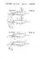
- FIG. 1is a perspective view of a battery powered implantable cardiac pacer including a universal externally programmable input/output circuit constructed in accordance with the invention.
- FIG. 2is a functional block diagram showing the principal elements of the cardiac pacer of FIG. 1.
- FIG. 3is a simplified schematic diagram of the input/output circuit of the cardiac pacer.
- FIG. 4is a simplified schematic diagram of the input/output circuit showing the principal components thereof configured for BIP sensing.
- FIG. 5is a simplified schematic diagram of the input/output circuit showing the principal components thereof configured for BIP pacing.
- FIG. 6is a simplified schematic diagram of the input/output circuit showing the principal components thereof configured for UNIP sensing.
- FIG. 7is a simplified schematic diagram of the input/output circuit showing the principal components thereof configured for UNIP pacing.
- a battery-operated implantable programmable cardiac pacer 10is shown implanted within a patient 11.
- the output of the paceris connected to the patient's heart 12 (shown in cross section) by means of pacer leads 13 and 14, which may be conventional in construction and operation.
- the pacer 10is preferably formed as a self-contained and hermetically sealed device such that its operation is unaffected by exposure to body fluids.
- Operation of the pacercan be modified as required by specific application by means of a multiplex-type monitor and control programmer apparatus 15 external to the patient.
- the apparatuswhich may be conventional in design and construction, includes a number of user-actuable controls by which the user can selectively vary certain operating functions and parameters of the pacer, including, in accordance with the invention, the input/output lead configuration.
- Communication between the control apparatus 15 and the paceris provided by a magnetic or radio-frequency transceiver 16 postioned by the user on the chest of the patient in close proximity to the implanted pacer.
- the transceivertransmits and receives telemetry data to and from the pacer in a manner well known to the art, and the resulting electrical signal is conveyed to and from the apparatus through a flexible electrical cable 17.
- the input/output circuits of pacer 10can be configured to operate in either a bipolar (BIP) mode or in a unipolar (UNIP) mode by actuating appropriate switches on apparatus 15.
- the implanted cardiac pacer 10is seen to include an atrial terminal 20 for connection to the atrium of the heart, and a ventricular terminal 21 for connection to the ventricle of the heart. These terminals are each coaxial in construction.
- the atrial terminal 20includes a cathode electrode 22 and a sleeve-shaped anode electrode 23.
- the ventricular terminal 21includes a central cathode electrode 24, and a sleeve-shaped anode electrode 25.
- the cathode and anode electrodes of each terminalare connected to an input/output circuit 26 wherein, in accordance with the invention, appropriate connections are established between the electrodes and the sensing and pacing circuitry of the pacer in accordance with a user-selected sense/pace operating mode.
- sense amplifier 30R-wave and P-wave signals developed on the atrial and ventricular terminals are applied to a sense amplifier 30 for amplification.
- sense amplifier 30has a bandpass characteristic which attenuates noise and other extraneous signals picked up by the pacer leads, so that the detected waves can be more effectively amplified.
- the amplified sense signalsare applied to a detector 31, which provides output pulses upon occurrence of the respective wave components in the sensed signal.
- the detector output pulsesare applied to a pulse control logic circuit 32, which under appropriate circumstances produces atrial and ventricular drive pulses for application to the input/output circuit 26. These drive pulses cause generation of pacer output pulses of predetermined amplitude and duration on the atrial and ventricular terminals for application to respective chambers of the heart by pacer leads 13 and 14.
- the control pulses applied to the input/output circuit 26include in addition to the atrial and ventricular drive pulses, atrial and ventricular charge dump pulses, which provide for a rapid depolarization of the electrodes immediately following each generated pacer pulse. Also, atrial and ventricular blanking pulses deactivate the sense amplifiers for approximately the duration of the drive and charge dump pulses from either channel.
- pulse control logic circuit 32may be controlled from an external location by means of multiplex circuit 33, which is adapted to receive on a pick-up element 34 an appropriately coded radio-frequency or magnetic control signal and generate appropriate control signals for application to pulse control logic circuit 32.
- multiplex circuit 33also provides two binary mode control signals, designated mode A and mode B signals, which are applied to input/output circuit 26 to control the interconnect mode of the circuit.
- input/output circuit 26is conditioned to one of the following four operating modes: UNIP sensing and UNIP pacing; or BIP sensing and BIP pacing; or UNIP sensing and BIP pacing; or BIP sensing and UNIP pacing.
- the input/output circuit 26 of the paceris seen to include an atrial circuit 36 and a ventricular circuit 36 within which atrial and ventricular signals are sensed and respective pacing pulses are developed.
- the atrial input circuitincludes a differential amplifier 37 for amplifying atrial signals received on terminal 20.
- the cathode 22 of terminal 20is connected to the inverting input of the differential amplifier through a capacitor 38 and a resistor 39, and the anode 23 of terminal 20 is connected to the non-inverting input of the differential amplifier through a capacitor 40 and a resistor 41.
- a resistor 42 connected between the output and the inverting input of differential amplifier 37provides degenerative feedback in accordance with conventional practice.
- the atrial pacing functionis accomplished by means of a pulse amplifier 43, which may be conventional in design and operation, and a capacitor 44 connected between the output of the amplifier and cathode electrode 22. In operation, amplifier 43 periodically produces output pulses in response to atrial drive signals developed in the pacer pulse control logic circuit 32.
- the atrial circuit 35includes in accordance with the invention PMOS transistors 45, 46 and 47.
- Transistor 45includes principal electrodes connected between the output of amplifier 43 and the pacer battery +V B , which forms the signal ground of the pacer.
- Transistor 46includes principal electrodes connected between anode 20 and +V B
- transistor 47includes principal electrodes connected between the non-inverting input of amplifier 48 and system ground.
- the ventricular circuit 36includes a differential amplifier 48 for amplifying ventricular signals received on terminal 21.
- the cathode 24 of terminal 21is connected to the inverting input of the differential amplifier through a capacitor 49 and a resistor 50, and the anode 25 of terminal 21 is connected to the non-inverting input of the differential amplifier through a capacitor 51 and a resistor 52.
- a resistor 42b connected between the output and the inverting input of differential amplifier 48provides degenerative feedback in accordance with conventional practice.
- the ventricular pacing functionis accomplished by means of a pulse amplifier 53, which may be conventional in design and operation, and a capacitor 54 connected between the output of the amplifier and cathode electrode 24.
- amplifier 48periodically produces output pulses in response to ventricular drive signals developed in the pacer pulse control logic circuit 32.
- the ventricular circuit 36includes, in accordance with the invention, PMOS transistors 55, 56 and 57.
- Transistor 55includes principal electrodes connected between the output of amplifier 53 and +V B .
- Transistor 56includes principal electrodes connected between anode 25 and +V B , and transistor 57 includes principal electrodes connected between the non-inverting input of amplifier 48 and system ground.
- any signal developed between the pacer lead tip electrodes of the connected bipolar leadis impressed through capacitors 38 and 40 to differential amplifier 37, wherein it is amplified for application to the pacer atrial sensing circuit.
- the differential amplifierdoes not respond to common-mode signals, such as artifacts and other interference signals, which appear on both terminals simultaneously.
- transistor 46When pacing in the BIP mode, as shown in FIG. 5, transistor 46 is biased into saturation, effectively grounding anode electrode 23 relative to any applied signal. Atrial stimulation pulses developed by amplifier 43 in response to applied atrial drive signals are applied to cathode electrode 22 through capacitor 44. Since the anode electrode is at signal ground, and transistor 63 is cut-off, the result is that virtually the entire output signal appears across the tip electrodes of the connected bipolar atrial pacer lead.
- the ventricular channel 36is similarly configured for BIP/UNIP sensing and pacing.
- transistors 55-57are biased into cut-off, as shown in FIG. 4, and ventricular signals present on the tip electrodes of a connected bipolar lead are applied to the inverting and non-inverting input terminals of differential amplifier 48.
- transistor 56is biased into saturation, effectively grounding cathode electrode 25, and transistor 63 is biased into cut-off, causing substantially the entire output signal to appear across the tip electrodes of the connected bipolar ventricular pacer lead.
- transistor 47When the input/output circuit 26 is conditioned for UNIP sensing, as shown in FIG. 6, within atrial channel 35 transistor 47 is biased into saturation, causing the non-inverting input of differential amplifier 37 to be effectively connected to signal ground. This results in the signal received on the tip electrode of the connected UNIP pacer lead to be applied to the inverting input.
- the case electrode 27may be connected to +V B at this time by a PMOS transistor 63, depending on the strapping of terminals A, B and C of a terminal block 64 on the pacer housing, to provide a return path through body fluid for the sensed signal.
- ventricular channel 36 in the UNIP sensing modeis similar to that of channel 35.
- Transistor 57is biased into saturation, causing the non-inverting input of differential amplifier 48 to be effectively at signal ground, and the ventricular signal developed on the tip electrode of the connected unipolar lead to be applied to the inverting input of differential amplifier 48.
- transistors 45-47 in atrial channel 35are biased into cut-off, causing the output pulse developed by amplifier 43 to be applied only to cathode electrode.
- transistor 63is biased into saturation by an applied control signal to connect the pacer housing to system ground.
- Transistors 55-57are biased to cut-off, and the output pulse developed by amplifier 53 is applied to cathode electrode 24.
- the grounded case electrode 27provides a return path for the pacing pulse.
- transistors 45 and 55The conduction state of transistors 45 and 55 is controlled by respective atrial and ventricular charge dump signals developed in pulse control logic circuit 32 and applied to the control electrodes of the devices on lines 73 and 74. These signals cause respective ones of transistors 45 and 55 to be driven into saturation for a short period of time following each atrial and ventricular output pulse, thereby discharging respective ones of capacitors 44 and 54 and allowing rapid depolarization of the associated electrodes.
- Atrial and ventricular drive pulses required for producing output pulses from amplifiers 43 and 48are developed by pulse control logic circuit 32 and applied to the inputs of the amplifiers on lines 75 and 76, respectively.
- P-waves detected by the atrial pacer lead and amplified by differential amplifier 37are applied to sense amplifier 30 (FIG. 2) by way of a signal line 77.
- R-wave signals detected by the ventricular pacer lead and amplified by differential amplifier 48are applied to sense amplifier 30 by way of a signal line 78.
- the atrial and ventricular channels 35 and 36may be conditioned to sense and/or pace in either a bipolar (BIP) or unipolar (UNIP) mode.
- the input/output circuit 26includes a mode control circuit comprising an AND gate 80, a plurality of NAND gates 81-84, an OR gate 85, a pair of NOR gates 86 and 87, an AND gate 88, and an exclusive NOR gate 89.
- the purpose of these logic elementsis to generate appropriate control signals to condition transistors 45, 47, 55, 57 and 63 into either cut-off or saturated states, as required by the operator-selected input/output mode.
- the input/output operating modeis determined by A and B mode designation signals developed in multiplex circuit 33. These mode designation signals are applied on respective control lines 90 and 91 to inputs of various ones of the logic elements, as shown in FIG. 3, to obtain pacing and sensing modes in accordance with the following table:
- the output logic OR gate 85becomes logic high, causing the output of logic AND gate 80 to become logic high. This biases transistor 63 into cut-off, and isolates the pacer housing electrode 27 from the system ground.
- either NAND gate 81 or NAND gate 82will provide a logic low output, depending on which output channel is active, to bias on the respective one of transistor 46 or transistor 56 for bipolar pacing. If contacts A and B of interconnect pad 64 are jumpered (instead of contacts A and C), then transistor 63 does not become conductive in the bipolar sensing mode, resulting in ungrounded differential sensing occurring.
- the A mode control signal and the B mode control signalare both logic high. This causes transistors 46 and 56 to be cutoff during sensing, and transistor 63 to be in saturation if contacts A and C are connected. As a result, each chamber of the heart is sensed in a differential mode with the pacemaker's housing serving as a ground electrode. If contacts A and B are connected (instead of A and C), then transistor 63 will be cutoff during sensing and no ground electrodes will be available. During an output pulse and subsequent charge dump, the appropriate one of transistors 56 and 46 will remain cut off and transistor 63 will remain conductive.
- both mode control signals A and Bare logic low, causing transistor 63 to be conductive and transistors 46 and 56 to be cut-off at all times.
- Transistors 60 and 61are also rendered conductive in this mode, so that the non-inverting inputs to the differential amplifiers are clamped to the reference voltage. Consequently, differential amplifiers 40 and 50 become single ended amplifiers, providing sensing between the pacer's case and the cathode's electrodes.
- the mode A control signalis logic low and the mode B control signal is logic high. This causes transistors 46 and 56 to be cut off, and transistor 63 to become conductive during sensing. During pacing and subsequent charge dump the outputs of NAND gates 81 and 82 become logic high. Depending on which channel is active, either transistor 46 or transistor 56 will become conductive. Transistor 63 is cut off at this time to disconnect the unipolar anode from the system.
- the operating mode of the input/output circuitmay be readily changed by external telemetry apparatus, changes in the patient which might occur following the implant of the pacer, and which would call for a different sensing or pacing lead configuration, can be non-invasively accomplished by the physician.
- the input/output circuit of the inventioncan be used in conjunction with a single channel pacer, as where only a ventricular channel is provided, to provide selective UNIP and BIP pacing and sensing modes in response to an externally applied control signal.
Landscapes
- Health & Medical Sciences (AREA)
- Cardiology (AREA)
- Heart & Thoracic Surgery (AREA)
- Life Sciences & Earth Sciences (AREA)
- Biophysics (AREA)
- Physiology (AREA)
- Engineering & Computer Science (AREA)
- Biomedical Technology (AREA)
- Nuclear Medicine, Radiotherapy & Molecular Imaging (AREA)
- Radiology & Medical Imaging (AREA)
- Animal Behavior & Ethology (AREA)
- General Health & Medical Sciences (AREA)
- Public Health (AREA)
- Veterinary Medicine (AREA)
- Electrotherapy Devices (AREA)
Abstract
Description
______________________________________ A B SENSE PACE ______________________________________ .0. .0. UNIP UNIP 1 .0. BIP BIP .0. 1 UNIP BIP 1 1 BIP UNIP ______________________________________
______________________________________ SENSING PACING ______________________________________ BIP UNIP Minimizes loss of energy at the out- put lead and prevents false inhibi- tion of the pacer by myopotentials. UNIP BIP Prevents stimulation of the pectoral muscle resulting from contact be- tween the muscle and the pacer housing. Allows a larger ampli- tude cardiac signal to be picked up because the amplitude is not subject to electrode orientation relative to the depolarization wavefront. UNIP UNIP Advantageous for patients with high stimulous thresholds and low cardiac amplitudes. BIP BIP Advantageous for patients with high myopotential amplitudes and pectoral muscle stimulation problems. ______________________________________
Claims (7)
Priority Applications (4)
| Application Number | Priority Date | Filing Date | Title |
|---|---|---|---|
| US06/459,806US4558702A (en) | 1983-01-21 | 1983-01-21 | Cardiac pacer having input/output circuit programmable for use with unipolar and bipolar pacer leads |
| EP84100570AEP0114679B2 (en) | 1983-01-21 | 1984-01-19 | Cardiac pacer having input/output circuit programmable for use with unipolar and bipolar pacer leads |
| DE8484100570TDE3471257D1 (en) | 1983-01-21 | 1984-01-19 | Cardiac pacer having input/output circuit programmable for use with unipolar and bipolar pacer leads |
| CA000445814ACA1226040A (en) | 1983-01-21 | 1984-01-20 | Cardiac pacer having input/output circuit programmable for use with unipolar and bipolar pacer leads |
Applications Claiming Priority (1)
| Application Number | Priority Date | Filing Date | Title |
|---|---|---|---|
| US06/459,806US4558702A (en) | 1983-01-21 | 1983-01-21 | Cardiac pacer having input/output circuit programmable for use with unipolar and bipolar pacer leads |
Publications (1)
| Publication Number | Publication Date |
|---|---|
| US4558702Atrue US4558702A (en) | 1985-12-17 |
Family
ID=23826222
Family Applications (1)
| Application Number | Title | Priority Date | Filing Date |
|---|---|---|---|
| US06/459,806Expired - LifetimeUS4558702A (en) | 1983-01-21 | 1983-01-21 | Cardiac pacer having input/output circuit programmable for use with unipolar and bipolar pacer leads |
Country Status (4)
| Country | Link |
|---|---|
| US (1) | US4558702A (en) |
| EP (1) | EP0114679B2 (en) |
| CA (1) | CA1226040A (en) |
| DE (1) | DE3471257D1 (en) |
Cited By (48)
| Publication number | Priority date | Publication date | Assignee | Title |
|---|---|---|---|---|
| US4741341A (en)* | 1986-03-12 | 1988-05-03 | Siemens-Pacesetter, Inc. | Protection circuit and method for implanted ECG telemetry circuits |
| US4741342A (en)* | 1986-03-11 | 1988-05-03 | Intermedics, Inc. | Cardiac pacemaker with selective unipolar/bipolar pacing |
| US4793353A (en)* | 1981-06-30 | 1988-12-27 | Borkan William N | Non-invasive multiprogrammable tissue stimulator and method |
| US4895152A (en)* | 1985-12-11 | 1990-01-23 | Telectronics N.V. | System for cardiac pacing |
| US4964407A (en)* | 1988-08-29 | 1990-10-23 | Intermedics, Inc. | Method and apparatus for assuring pacer programming is compatible with the lead |
| US4991583A (en)* | 1986-08-13 | 1991-02-12 | Siemens-Pacesetter, Inc. | Pacemaker having independently programmable electrode configuration for pacing and sensing and method for operation thereof |
| US5003975A (en)* | 1988-04-19 | 1991-04-02 | Siemens-Pacesetter, Inc. | Automatic electrode configuration of an implantable pacemaker |
| US5095902A (en)* | 1989-08-28 | 1992-03-17 | Siemens Aktiengesellschaft | Implantable medical stimulation system optionally operable in a bipolar or a unipolar mode |
| US5133353A (en)* | 1990-04-25 | 1992-07-28 | Cardiac Pacemakers, Inc. | Implantable intravenous cardiac stimulation system with pulse generator housing serving as optional additional electrode |
| US5312448A (en)* | 1989-09-07 | 1994-05-17 | Siemens Aktiengesellschaft | Medical appliance for stimulating tissue contractions |
| US5620477A (en)* | 1994-03-31 | 1997-04-15 | Ventritex, Inc. | Pulse generator with case that can be active or inactive |
| US5658321A (en)* | 1995-06-09 | 1997-08-19 | Ventritex, Inc. | Conductive housing for implantable cardiac device |
| US6381494B1 (en) | 1999-08-20 | 2002-04-30 | Cardiac Pacemakers, Inc. | Response to ambient noise in implantable pulse generator |
| US20020107551A1 (en)* | 2000-12-26 | 2002-08-08 | Stahmann Jeffrey E. | Pacing and sensing vectors |
| US20040243194A1 (en)* | 1999-08-20 | 2004-12-02 | Cardiac Pacemakers, Inc. | Implantable pulse generator and method having adjustable signal blanking |
| US20050119707A1 (en)* | 1990-04-25 | 2005-06-02 | Cardiac Pacemakers, Inc. | Subcutaneous cardiac rhythm management |
| US7110815B2 (en) | 2002-05-06 | 2006-09-19 | Cardiac Pacemakers, Inc. | System and method for providing temporary stimulation therapy to optimize chronic electrical performance for electrodes used in conjunction with a cardiac rhythm management system |
| US20060271110A1 (en)* | 2005-05-31 | 2006-11-30 | Vernon Scott D | Apparatus for tissue stimulation |
| US20070135851A1 (en)* | 2000-08-29 | 2007-06-14 | Cardiac Pacemakers, Inc. | Implantable pulse generator and method having adjustable signal blanking |
| US7389140B1 (en)* | 2004-06-16 | 2008-06-17 | Kroll Mark W | Adjustment of stimulation current path |
| US9308378B2 (en) | 2013-05-03 | 2016-04-12 | Alfred E. Mann Foundation For Scientific Research | Implant recharger handshaking system and method |
| US9427574B2 (en) | 2014-08-15 | 2016-08-30 | Axonics Modulation Technologies, Inc. | Implantable lead affixation structure for nerve stimulation to alleviate bladder dysfunction and other indication |
| US9433779B2 (en) | 2013-05-03 | 2016-09-06 | Alfred E. Mann Foundation For Scientific Research | Multi-branch stimulation electrode for subcutaneous field stimulation |
| US9446241B2 (en) | 2013-03-15 | 2016-09-20 | Alfred E. Mann Foundation For Scientific Research | Current sensing multiple output current stimulators |
| US9517338B1 (en) | 2016-01-19 | 2016-12-13 | Axonics Modulation Technologies, Inc. | Multichannel clip device and methods of use |
| US9533155B2 (en) | 2014-08-15 | 2017-01-03 | Axonics Modulation Technologies, Inc. | Methods for determining neurostimulation electrode configurations based on neural localization |
| US9555246B2 (en) | 2014-08-15 | 2017-01-31 | Axonics Modulation Technologies, Inc. | Electromyographic lead positioning and stimulation titration in a nerve stimulation system for treatment of overactive bladder |
| US9675807B2 (en) | 2013-05-03 | 2017-06-13 | Alfred E. Mann Foundation For Scientific Research | High reliability wire welding for implantable devices |
| US9682237B2 (en) | 2013-03-15 | 2017-06-20 | Alfred E. Mann Foundation For Scientific Research | High voltage monitoring successive approximation analog to digital converter |
| US9700731B2 (en) | 2014-08-15 | 2017-07-11 | Axonics Modulation Technologies, Inc. | Antenna and methods of use for an implantable nerve stimulator |
| US9728981B2 (en) | 2012-08-31 | 2017-08-08 | Alfred E. Mann Foundation For Scientific Research | Feedback controlled coil driver for inductive power transfer |
| US9780596B2 (en) | 2013-07-29 | 2017-10-03 | Alfred E. Mann Foundation For Scientific Research | Microprocessor controlled class E driver |
| US9802051B2 (en) | 2014-08-15 | 2017-10-31 | Axonics Modulation Technologies, Inc. | External pulse generator device and associated methods for trial nerve stimulation |
| US9855436B2 (en) | 2013-07-29 | 2018-01-02 | Alfred E. Mann Foundation For Scientific Research | High efficiency magnetic link for implantable devices |
| US9895546B2 (en) | 2015-01-09 | 2018-02-20 | Axonics Modulation Technologies, Inc. | Patient remote and associated methods of use with a nerve stimulation system |
| US9925381B2 (en) | 2015-07-10 | 2018-03-27 | Axonics Modulation Technologies, Inc. | Implantable nerve stimulator having internal electronics without ASIC and methods of use |
| US10092762B2 (en) | 2014-08-15 | 2018-10-09 | Axonics Modulation Technologies, Inc. | Integrated electromyographic clinician programmer for use with an implantable neurostimulator |
| US10195423B2 (en) | 2016-01-19 | 2019-02-05 | Axonics Modulation Technologies, Inc. | Multichannel clip device and methods of use |
| US10376704B2 (en) | 2016-02-12 | 2019-08-13 | Axonics Modulation Technologies, Inc. | External pulse generator device and associated methods for trial nerve stimulation |
| WO2019172993A1 (en)* | 2018-03-06 | 2019-09-12 | Cardioinsight Technologies, Inc. | Channel integrity detection and reconstruction of electrophysiological signals |
| US10561835B2 (en) | 2006-10-31 | 2020-02-18 | Medtronic, Inc. | Implantable medical lead with threaded fixation |
| US10682521B2 (en) | 2014-08-15 | 2020-06-16 | Axonics Modulation Technologies, Inc. | Attachment devices and associated methods of use with a nerve stimulation charging device |
| US11110283B2 (en) | 2018-02-22 | 2021-09-07 | Axonics, Inc. | Neurostimulation leads for trial nerve stimulation and methods of use |
| US11439829B2 (en) | 2019-05-24 | 2022-09-13 | Axonics, Inc. | Clinician programmer methods and systems for maintaining target operating temperatures |
| US11484723B2 (en) | 2015-01-09 | 2022-11-01 | Axonics, Inc. | Attachment devices and associated methods of use with a nerve stimulation charging device |
| US11642537B2 (en) | 2019-03-11 | 2023-05-09 | Axonics, Inc. | Charging device with off-center coil |
| US11848090B2 (en) | 2019-05-24 | 2023-12-19 | Axonics, Inc. | Trainer for a neurostimulator programmer and associated methods of use with a neurostimulation system |
| US12420103B1 (en) | 2020-08-20 | 2025-09-23 | Axonics, Inc. | Neurostimulation leads with reduced current leakage |
Families Citing this family (8)
| Publication number | Priority date | Publication date | Assignee | Title |
|---|---|---|---|---|
| US4741339A (en)* | 1984-10-22 | 1988-05-03 | Cochlear Pty. Limited | Power transfer for implanted prostheses |
| US4726379A (en)* | 1985-11-14 | 1988-02-23 | Cardiac Control Systems, Inc. | Cardiac pacer with switching circuit for isolation |
| IT1214738B (en)* | 1986-11-11 | 1990-01-18 | Sbm Soc Brevetti Medicina | IMPROVEMENT IN CARDIAC STIMULATION SYSTEMS VIA PACEMAKER |
| EP0308536B2 (en)* | 1987-09-24 | 1999-06-23 | Pacesetter, Inc. | Pacemaker having programmable configuration |
| GB2214813A (en)* | 1988-01-14 | 1989-09-13 | Stuart Charles Webb | Rate-responsive pacemaker |
| DE68927447T2 (en)* | 1988-02-17 | 1997-04-03 | Lewis | Frequency-sensitive pacemaker |
| AU614118B2 (en)* | 1988-04-19 | 1991-08-22 | Pacesetter Ab | Configuration programming of an implantable pacemaker |
| US5265602A (en)* | 1992-07-13 | 1993-11-30 | Medtronic, Inc. | Ring-to-ring cardiac electrogram pacemaker |
Citations (4)
| Publication number | Priority date | Publication date | Assignee | Title |
|---|---|---|---|---|
| US4055189A (en)* | 1975-05-19 | 1977-10-25 | Medalert Corporation | Condition monitoring pacer |
| GB2026870A (en)* | 1978-07-20 | 1980-02-13 | Medtronic Inc | Body implantable pacemaker |
| EP0030897A1 (en)* | 1979-12-18 | 1981-06-24 | Cardiofrance- Compagnie Francaise D'electrocardiologie | Polyvalent implantable cardiac pacemaker |
| US4402322A (en)* | 1981-03-25 | 1983-09-06 | Medtronic, Inc. | Pacer output circuit |
Family Cites Families (4)
| Publication number | Priority date | Publication date | Assignee | Title |
|---|---|---|---|---|
| US3735766A (en)* | 1971-04-19 | 1973-05-29 | Gen Electric | Optional unipolar-bipolar body organ stimulator |
| WO1979000070A1 (en)* | 1977-07-27 | 1979-02-22 | S Joseph | Heart stimulating apparatus |
| FR2440197A1 (en)* | 1978-11-06 | 1980-05-30 | Medtronic Inc | ON-DEMAND CARDIAC STIMULATOR DETECTION AMPLIFIER |
| FR2491659B1 (en)* | 1980-10-07 | 1986-04-04 | Medtronic Inc | TELEMETRY DEVICE FOR AN IMPLANTABLE STIMULATOR |
- 1983
- 1983-01-21USUS06/459,806patent/US4558702A/ennot_activeExpired - Lifetime
- 1984
- 1984-01-19EPEP84100570Apatent/EP0114679B2/ennot_activeExpired - Lifetime
- 1984-01-19DEDE8484100570Tpatent/DE3471257D1/ennot_activeExpired
- 1984-01-20CACA000445814Apatent/CA1226040A/ennot_activeExpired
Patent Citations (4)
| Publication number | Priority date | Publication date | Assignee | Title |
|---|---|---|---|---|
| US4055189A (en)* | 1975-05-19 | 1977-10-25 | Medalert Corporation | Condition monitoring pacer |
| GB2026870A (en)* | 1978-07-20 | 1980-02-13 | Medtronic Inc | Body implantable pacemaker |
| EP0030897A1 (en)* | 1979-12-18 | 1981-06-24 | Cardiofrance- Compagnie Francaise D'electrocardiologie | Polyvalent implantable cardiac pacemaker |
| US4402322A (en)* | 1981-03-25 | 1983-09-06 | Medtronic, Inc. | Pacer output circuit |
Cited By (102)
| Publication number | Priority date | Publication date | Assignee | Title |
|---|---|---|---|---|
| US4793353A (en)* | 1981-06-30 | 1988-12-27 | Borkan William N | Non-invasive multiprogrammable tissue stimulator and method |
| US4895152A (en)* | 1985-12-11 | 1990-01-23 | Telectronics N.V. | System for cardiac pacing |
| US4741342A (en)* | 1986-03-11 | 1988-05-03 | Intermedics, Inc. | Cardiac pacemaker with selective unipolar/bipolar pacing |
| US4741341A (en)* | 1986-03-12 | 1988-05-03 | Siemens-Pacesetter, Inc. | Protection circuit and method for implanted ECG telemetry circuits |
| US4991583A (en)* | 1986-08-13 | 1991-02-12 | Siemens-Pacesetter, Inc. | Pacemaker having independently programmable electrode configuration for pacing and sensing and method for operation thereof |
| US5003975A (en)* | 1988-04-19 | 1991-04-02 | Siemens-Pacesetter, Inc. | Automatic electrode configuration of an implantable pacemaker |
| US4964407A (en)* | 1988-08-29 | 1990-10-23 | Intermedics, Inc. | Method and apparatus for assuring pacer programming is compatible with the lead |
| US5095902A (en)* | 1989-08-28 | 1992-03-17 | Siemens Aktiengesellschaft | Implantable medical stimulation system optionally operable in a bipolar or a unipolar mode |
| US5312448A (en)* | 1989-09-07 | 1994-05-17 | Siemens Aktiengesellschaft | Medical appliance for stimulating tissue contractions |
| US5133353A (en)* | 1990-04-25 | 1992-07-28 | Cardiac Pacemakers, Inc. | Implantable intravenous cardiac stimulation system with pulse generator housing serving as optional additional electrode |
| AU641224B2 (en)* | 1990-04-25 | 1993-09-16 | Cardiac Pacemakers, Inc. | Implantable intravenous cardiac stimulation system with pulse generator housing serving as optional additional electrode |
| US5385574A (en)* | 1990-04-25 | 1995-01-31 | Cardiac Pacemakers, Inc. | Implantable intravenous cardiac stimulation system with pulse generator housing serving as optional additional electrode |
| US7522959B2 (en) | 1990-04-25 | 2009-04-21 | Cardiac Pacemakers, Inc. | Subcutaneous cardiac rhythm management |
| US20050119707A1 (en)* | 1990-04-25 | 2005-06-02 | Cardiac Pacemakers, Inc. | Subcutaneous cardiac rhythm management |
| US6999814B2 (en) | 1990-04-25 | 2006-02-14 | Cardiac Pacemakers, Inc. | Implantable intravenous cardiac stimulation system with pulse generator housing serving as optional additional electrode |
| US5620477A (en)* | 1994-03-31 | 1997-04-15 | Ventritex, Inc. | Pulse generator with case that can be active or inactive |
| US5658321A (en)* | 1995-06-09 | 1997-08-19 | Ventritex, Inc. | Conductive housing for implantable cardiac device |
| US20040243194A1 (en)* | 1999-08-20 | 2004-12-02 | Cardiac Pacemakers, Inc. | Implantable pulse generator and method having adjustable signal blanking |
| US7200436B2 (en) | 1999-08-20 | 2007-04-03 | Cardiac Pacemakers, Inc. | Implantable pulse generator and method having adjustable signal blanking |
| US6873875B1 (en) | 1999-08-20 | 2005-03-29 | Cardiac Pacemakers, Inc. | Implantable pulse generator and method having adjustable signal blanking |
| US6381494B1 (en) | 1999-08-20 | 2002-04-30 | Cardiac Pacemakers, Inc. | Response to ambient noise in implantable pulse generator |
| US20100324622A1 (en)* | 2000-08-29 | 2010-12-23 | Gilkerson James O | Implantable pulse generator and method having adjustable signal blanking |
| US7801606B2 (en) | 2000-08-29 | 2010-09-21 | Cardiac Pacemakers, Inc. | Implantable pulse generator and method having adjustable signal blanking |
| US20070135851A1 (en)* | 2000-08-29 | 2007-06-14 | Cardiac Pacemakers, Inc. | Implantable pulse generator and method having adjustable signal blanking |
| US8214037B2 (en) | 2000-08-29 | 2012-07-03 | Cardiac Pacemakers, Inc. | Implantable pulse generator and method having adjustable signal blanking |
| US7974692B2 (en) | 2000-08-29 | 2011-07-05 | Cardiac Pacemakers, Inc. | Implantable pulse generator and method having adjustable signal blanking |
| US7130682B2 (en)* | 2000-12-26 | 2006-10-31 | Cardiac Pacemakers, Inc. | Pacing and sensing vectors |
| US20020107551A1 (en)* | 2000-12-26 | 2002-08-08 | Stahmann Jeffrey E. | Pacing and sensing vectors |
| US7945325B2 (en) | 2001-02-08 | 2011-05-17 | Cardiac Pacemakers, Inc. | Pacing and sensing vectors |
| US9278221B2 (en) | 2001-02-08 | 2016-03-08 | Cardiac Pacemakers, Inc. | Pacing and sensing vectors |
| US8798744B2 (en) | 2001-02-08 | 2014-08-05 | Cardiac Pacemakers, Inc. | Pacing and sensing vectors |
| US20160136433A1 (en)* | 2001-02-08 | 2016-05-19 | Cardiac Pacemakers, Inc. | Pacing and sensing vectors |
| US7991468B2 (en) | 2001-02-08 | 2011-08-02 | Cardiac Pacemakers, Inc. | Pacing and sensing vectors |
| US7110815B2 (en) | 2002-05-06 | 2006-09-19 | Cardiac Pacemakers, Inc. | System and method for providing temporary stimulation therapy to optimize chronic electrical performance for electrodes used in conjunction with a cardiac rhythm management system |
| US7389140B1 (en)* | 2004-06-16 | 2008-06-17 | Kroll Mark W | Adjustment of stimulation current path |
| US7715911B2 (en) | 2005-05-31 | 2010-05-11 | Medtronic, Inc. | Apparatus for tissue stimulation |
| US20100256711A1 (en)* | 2005-05-31 | 2010-10-07 | Medtronic, Inc. | Apparatus for tissue stimulation |
| US20060271110A1 (en)* | 2005-05-31 | 2006-11-30 | Vernon Scott D | Apparatus for tissue stimulation |
| US8290583B2 (en) | 2005-05-31 | 2012-10-16 | Medtronic, Inc. | Apparatus for tissue stimulation |
| US10561835B2 (en) | 2006-10-31 | 2020-02-18 | Medtronic, Inc. | Implantable medical lead with threaded fixation |
| US9728981B2 (en) | 2012-08-31 | 2017-08-08 | Alfred E. Mann Foundation For Scientific Research | Feedback controlled coil driver for inductive power transfer |
| US9981130B2 (en) | 2013-03-15 | 2018-05-29 | Alfred E. Mann Foundation For Scientific Research | Current sensing multiple output current stimulators |
| US9446241B2 (en) | 2013-03-15 | 2016-09-20 | Alfred E. Mann Foundation For Scientific Research | Current sensing multiple output current stimulators |
| US11338144B2 (en) | 2013-03-15 | 2022-05-24 | Alfred E. Mann Foundation For Scientific Research | Current sensing multiple output current stimulators |
| US9682237B2 (en) | 2013-03-15 | 2017-06-20 | Alfred E. Mann Foundation For Scientific Research | High voltage monitoring successive approximation analog to digital converter |
| US10603495B2 (en) | 2013-03-15 | 2020-03-31 | The Alfred E. Mann Foundation For Scientific Research | Current sensing multiple output current stimulators |
| US9433779B2 (en) | 2013-05-03 | 2016-09-06 | Alfred E. Mann Foundation For Scientific Research | Multi-branch stimulation electrode for subcutaneous field stimulation |
| US9675807B2 (en) | 2013-05-03 | 2017-06-13 | Alfred E. Mann Foundation For Scientific Research | High reliability wire welding for implantable devices |
| US9308378B2 (en) | 2013-05-03 | 2016-04-12 | Alfred E. Mann Foundation For Scientific Research | Implant recharger handshaking system and method |
| US9789325B2 (en) | 2013-05-03 | 2017-10-17 | Alfred E. Mann Foundation For Scientific Research | Implant recharger handshaking system and method |
| US10029090B2 (en) | 2013-05-03 | 2018-07-24 | Alfred E. Mann Foundation For Scientific Research | Multi-branch stimulation electrode for subcutaneous field stimulation |
| US10971950B2 (en) | 2013-07-29 | 2021-04-06 | The Alfred E. Mann Foundation For Scientific Research | Microprocessor controlled class E driver |
| US11722007B2 (en) | 2013-07-29 | 2023-08-08 | The Alfred E. Mann Foundation For Scientific Rsrch | Microprocessor controlled class E driver |
| US10449377B2 (en) | 2013-07-29 | 2019-10-22 | The Alfred E. Mann Foundation For Scientific Research | High efficiency magnetic link for implantable devices |
| US9780596B2 (en) | 2013-07-29 | 2017-10-03 | Alfred E. Mann Foundation For Scientific Research | Microprocessor controlled class E driver |
| US10447083B2 (en) | 2013-07-29 | 2019-10-15 | The Alfred E. Mann Foundation For Scientific Research | Microprocessor controlled class E driver |
| US9855436B2 (en) | 2013-07-29 | 2018-01-02 | Alfred E. Mann Foundation For Scientific Research | High efficiency magnetic link for implantable devices |
| US9700731B2 (en) | 2014-08-15 | 2017-07-11 | Axonics Modulation Technologies, Inc. | Antenna and methods of use for an implantable nerve stimulator |
| US9533155B2 (en) | 2014-08-15 | 2017-01-03 | Axonics Modulation Technologies, Inc. | Methods for determining neurostimulation electrode configurations based on neural localization |
| US11730411B2 (en) | 2014-08-15 | 2023-08-22 | Axonics, Inc. | Methods for determining neurostimulation electrode configurations based on neural localization |
| US9855423B2 (en) | 2014-08-15 | 2018-01-02 | Axonics Modulation Technologies, Inc. | Systems and methods for neurostimulation electrode configurations based on neural localization |
| US9802038B2 (en) | 2014-08-15 | 2017-10-31 | Axonics Modulation Technologies, Inc. | Implantable lead affixation structure for nerve stimulation to alleviate bladder dysfunction and other indication |
| US10092762B2 (en) | 2014-08-15 | 2018-10-09 | Axonics Modulation Technologies, Inc. | Integrated electromyographic clinician programmer for use with an implantable neurostimulator |
| US9427574B2 (en) | 2014-08-15 | 2016-08-30 | Axonics Modulation Technologies, Inc. | Implantable lead affixation structure for nerve stimulation to alleviate bladder dysfunction and other indication |
| US11497916B2 (en) | 2014-08-15 | 2022-11-15 | Axonics, Inc. | Electromyographic lead positioning and stimulation titration in a nerve stimulation system for treatment of overactive bladder |
| US11389659B2 (en) | 2014-08-15 | 2022-07-19 | Axonics, Inc. | External pulse generator device and associated methods for trial nerve stimulation |
| US11213675B2 (en) | 2014-08-15 | 2022-01-04 | Axonics, Inc. | Implantable lead affixation structure for nerve stimulation to alleviate bladder dysfunction and other indication |
| US10406369B2 (en) | 2014-08-15 | 2019-09-10 | Axonics Modulation Technologies, Inc. | Electromyographic lead positioning and stimulation titration in a nerve stimulation system for treatment of overactive bladder |
| US11116985B2 (en) | 2014-08-15 | 2021-09-14 | Axonics, Inc. | Clinician programmer for use with an implantable neurostimulation lead |
| US9802051B2 (en) | 2014-08-15 | 2017-10-31 | Axonics Modulation Technologies, Inc. | External pulse generator device and associated methods for trial nerve stimulation |
| US10729903B2 (en) | 2014-08-15 | 2020-08-04 | Axonics Modulation Technologies, Inc. | Methods for determining neurostimulation electrode configurations based on neural localization |
| US10478619B2 (en) | 2014-08-15 | 2019-11-19 | Axonics Modulation Technologies, Inc. | Implantable lead affixation structure for nerve stimulation to alleviate bladder dysfunction and other indication |
| US9561372B2 (en) | 2014-08-15 | 2017-02-07 | Axonics Modulation Technologies, Inc. | Electromyographic lead positioning and stimulation titration in a nerve stimulation system for treatment of overactive bladder |
| US10589103B2 (en) | 2014-08-15 | 2020-03-17 | Axonics Modulation Technologies, Inc. | External pulse generator device and associated methods for trial nerve stimulation |
| US9555246B2 (en) | 2014-08-15 | 2017-01-31 | Axonics Modulation Technologies, Inc. | Electromyographic lead positioning and stimulation titration in a nerve stimulation system for treatment of overactive bladder |
| US10682521B2 (en) | 2014-08-15 | 2020-06-16 | Axonics Modulation Technologies, Inc. | Attachment devices and associated methods of use with a nerve stimulation charging device |
| US10384067B2 (en) | 2015-01-09 | 2019-08-20 | Axonics Modulation Technologies, Inc. | Patient remote and associated methods of use with a nerve stimulation system |
| US11478648B2 (en) | 2015-01-09 | 2022-10-25 | Axonics, Inc. | Antenna and methods of use for an implantable nerve stimulator |
| US10105542B2 (en) | 2015-01-09 | 2018-10-23 | Axonics Modulation Technologies, Inc. | Patient remote and associated methods of use with a nerve stimulation system |
| US9895546B2 (en) | 2015-01-09 | 2018-02-20 | Axonics Modulation Technologies, Inc. | Patient remote and associated methods of use with a nerve stimulation system |
| US10722721B2 (en) | 2015-01-09 | 2020-07-28 | Axonics Modulation Technologies, Inc. | Antenna and methods of use for an implantable nerve stimulator |
| US11123569B2 (en) | 2015-01-09 | 2021-09-21 | Axonics, Inc. | Patient remote and associated methods of use with a nerve stimulation system |
| US9770596B2 (en) | 2015-01-09 | 2017-09-26 | Axonics Modulation Technologies, Inc. | Antenna and methods of use for an implantable nerve stimulator |
| US11484723B2 (en) | 2015-01-09 | 2022-11-01 | Axonics, Inc. | Attachment devices and associated methods of use with a nerve stimulation charging device |
| US10850104B2 (en) | 2015-07-10 | 2020-12-01 | Axonics Modulation Technologies, Inc. | Implantable nerve stimulator having internal electronics without ASIC and methods of use |
| US11766568B2 (en) | 2015-07-10 | 2023-09-26 | Axonics, Inc. | Implantable nerve stimulator having internal electronics without ASIC and methods of use |
| US9925381B2 (en) | 2015-07-10 | 2018-03-27 | Axonics Modulation Technologies, Inc. | Implantable nerve stimulator having internal electronics without ASIC and methods of use |
| US9517338B1 (en) | 2016-01-19 | 2016-12-13 | Axonics Modulation Technologies, Inc. | Multichannel clip device and methods of use |
| US10195423B2 (en) | 2016-01-19 | 2019-02-05 | Axonics Modulation Technologies, Inc. | Multichannel clip device and methods of use |
| US10376704B2 (en) | 2016-02-12 | 2019-08-13 | Axonics Modulation Technologies, Inc. | External pulse generator device and associated methods for trial nerve stimulation |
| US12226643B2 (en) | 2016-02-12 | 2025-02-18 | Axonics, Inc. | External pulse generator device and affixation device for trial nerve stimulation and methods of use |
| US11260236B2 (en) | 2016-02-12 | 2022-03-01 | Axonics, Inc. | External pulse generator device and affixation device for trial nerve stimulation and methods of use |
| US12042662B2 (en) | 2018-02-22 | 2024-07-23 | Axonics, Inc. | Neurostimulation leads for trial nerve stimulation and methods of use |
| US11511122B2 (en) | 2018-02-22 | 2022-11-29 | Axonics, Inc. | Neurostimulation leads for trial nerve stimulation and methods of use |
| US11110283B2 (en) | 2018-02-22 | 2021-09-07 | Axonics, Inc. | Neurostimulation leads for trial nerve stimulation and methods of use |
| WO2019172993A1 (en)* | 2018-03-06 | 2019-09-12 | Cardioinsight Technologies, Inc. | Channel integrity detection and reconstruction of electrophysiological signals |
| US12059260B2 (en) | 2018-03-06 | 2024-08-13 | Cardioinsight Technologies Inc. | Channel integrity detection and reconstruction of electrophysiological signals |
| US10874318B2 (en) | 2018-03-06 | 2020-12-29 | Cardioinsight Technologies, Inc. | Channel integrity detection and reconstruction of electrophysiological signals |
| US11642537B2 (en) | 2019-03-11 | 2023-05-09 | Axonics, Inc. | Charging device with off-center coil |
| US11848090B2 (en) | 2019-05-24 | 2023-12-19 | Axonics, Inc. | Trainer for a neurostimulator programmer and associated methods of use with a neurostimulation system |
| US11439829B2 (en) | 2019-05-24 | 2022-09-13 | Axonics, Inc. | Clinician programmer methods and systems for maintaining target operating temperatures |
| US12420103B1 (en) | 2020-08-20 | 2025-09-23 | Axonics, Inc. | Neurostimulation leads with reduced current leakage |
Also Published As
| Publication number | Publication date |
|---|---|
| EP0114679A3 (en) | 1984-08-22 |
| DE3471257D1 (en) | 1988-06-23 |
| CA1226040A (en) | 1987-08-25 |
| EP0114679B2 (en) | 1997-07-23 |
| EP0114679B1 (en) | 1988-05-18 |
| EP0114679A2 (en) | 1984-08-01 |
Similar Documents
| Publication | Publication Date | Title |
|---|---|---|
| US4558702A (en) | Cardiac pacer having input/output circuit programmable for use with unipolar and bipolar pacer leads | |
| EP0923401B1 (en) | A stimulation device | |
| US4628934A (en) | Method and means of electrode selection for pacemaker with multielectrode leads | |
| US6658294B1 (en) | Implantable cardiac device having an impedance monitoring circuit and method | |
| US4387717A (en) | Pacer internal cardiac electrogram sensing system | |
| US6016446A (en) | Cardiac rhythm management system including nonlinear, non-blanking sense amplifier | |
| US6275734B1 (en) | Efficient generation of sensing signals in an implantable medical device such as a pacemaker or ICD | |
| US4379459A (en) | Cardiac pacemaker sense amplifier | |
| US6600952B1 (en) | Secure telemetry system and method for an implantable cardiac stimulation device | |
| US6721598B1 (en) | Coronary sinus cardiac lead for stimulating and sensing in the right and left heart and system | |
| US5571143A (en) | Heart Stimulator | |
| US5265602A (en) | Ring-to-ring cardiac electrogram pacemaker | |
| US5817130A (en) | Implantable cardiac cardioverter/defibrillator with EMI suppression filter with independent ground connection | |
| US4310000A (en) | Implantable pulse generator having separate passive sensing reference electrode | |
| JP2805214B2 (en) | Method and apparatus for reliably programming a pacemaker | |
| US4114627A (en) | Cardiac pacer system and method with capture verification signal | |
| US6735472B2 (en) | Method of defibrillating a heart with electrode configurations including a left ventricular defibrillation electrode | |
| US6658283B1 (en) | Implantable cardiac stimulation device, system and method which provides an electrogram signal having the appearance of a surface electrocardiogram | |
| US5620473A (en) | Calibration system for pacemaker-generated intracardiac electrogram | |
| US6907291B1 (en) | Secure telemetry system and method for an implantable cardiac stimulation device | |
| JPH0328227B2 (en) | ||
| US7024241B1 (en) | Pacing pulse waveforms that support simultaneous intracardiac signal sensing and analysis | |
| US3625201A (en) | Tester for standby cardiac pacing | |
| US4513752A (en) | Bipolar sensing system | |
| US6658289B2 (en) | Universal pacing and defibrillation system |
Legal Events
| Date | Code | Title | Description |
|---|---|---|---|
| AS | Assignment | Owner name:CORDIS CORPORATION, MIAMI, FL A CORP. OF FL Free format text:ASSIGNMENT OF ASSIGNORS INTEREST.;ASSIGNORS:BARRERAS, FRANCISCO J.;MARTUCCI, JAMES P.;REEL/FRAME:004088/0835;SIGNING DATES FROM 19821220 TO 19830103 | |
| STCF | Information on status: patent grant | Free format text:PATENTED CASE | |
| AS | Assignment | Owner name:TELECTRONICS, N.V., DE RUYTERKADE 58A, CURACAO, NE Free format text:ASSIGNMENT OF ASSIGNORS INTEREST.;ASSIGNOR:TNC MEDICAL DEVICES PTE. LTD.;REEL/FRAME:004748/0373 Effective date:19870430 Owner name:TELECTRONICS, N.V., NAMIBIA Free format text:ASSIGNMENT OF ASSIGNORS INTEREST;ASSIGNOR:TNC MEDICAL DEVICES PTE. LTD.;REEL/FRAME:004748/0373 Effective date:19870430 | |
| AS | Assignment | Owner name:SOUTHEAST BANK, N.A., MIDLAD BANK PLC (SINGAPORE B Free format text:SECURITY INTEREST;ASSIGNOR:TELECTRONICS N.V.;REEL/FRAME:004748/0364 Effective date:19870612 | |
| AS | Assignment | Owner name:SOUTHEAST BANK, N.A. Free format text:SECURITY INTEREST;ASSIGNOR:TELECTRONICS N.V.;REEL/FRAME:004747/0217 Effective date:19870630 Owner name:CREDIT LYONNAIS (CAYMAN ISLANDS BRANCH) Free format text:SECURITY INTEREST;ASSIGNOR:TELECTRONICS N.V.;REEL/FRAME:004747/0217 Effective date:19870630 Owner name:MIDLAND BANK PLC (SINGAPORE BRANCH) Free format text:SECURITY INTEREST;ASSIGNOR:TELECTRONICS N.V.;REEL/FRAME:004747/0217 Effective date:19870630 | |
| AS | Assignment | Owner name:TELECTRONICS N.V., NETHERLANDS ANTILLES Free format text:RELEASED BY SECURED PARTY;ASSIGNOR:SOUTHEAST BANKN.A., MIDLAND BANK PLC AND CREDIT LYONNAIS;REEL/FRAME:005002/0786 Effective date:19880615 | |
| FPAY | Fee payment | Year of fee payment:4 | |
| AS | Assignment | Owner name:TELECTRONICS PACING SYSTEMS, INC., COLORADO Free format text:ASSIGNORS HEREBY CONFIRMS THE ENTIRE INTEREST IN SAID INVENTIONS TO ASSIGNEE ELECUTED ON SEPT. 16, 1988;ASSIGNORS:TELECTRONICS PTY. LTD.;MEDICAL TELECTRONICS HOLDING & FINANCE CO.;TELECTRONIC NV;AND OTHERS;REEL/FRAME:006172/0028 Effective date:19920622 | |
| FPAY | Fee payment | Year of fee payment:8 | |
| AS | Assignment | Owner name:TELECTRONICS PACING SYSTEMS, INC., COLORADO Free format text:CORRECTIVE ASSIGNMENT TO CORRECT ASSIGNEE'S STATE OF INCORPORATION. AN ASSIGNMENT WAS PREVIOUSLY RECORDED AT REEL 6172, FRAME 0028;ASSIGNORS:TELECTRONICS PTY. LTD., AN AUSTRALIAN COMPANY;MEDICAL TELECTRONICS HOLDING & FINANCE CO. (BV), A DUTCH COMPANY;TELECTRONICS NV, A COMPANY OF THE NETHERLANDS ANTILLES;AND OTHERS;REEL/FRAME:008321/0072 Effective date:19961101 | |
| AS | Assignment | Owner name:PACESETTER, INC., CALIFORNIA Free format text:ASSIGNMENT OF ASSIGNORS INTEREST;ASSIGNOR:TELECTRONICS PACING SYSTEMS;REEL/FRAME:008454/0461 Effective date:19961129 | |
| FPAY | Fee payment | Year of fee payment:12 |