US4558388A - Substrate and substrate holder - Google Patents
Substrate and substrate holderDownload PDFInfo
- Publication number
- US4558388A US4558388AUS06/548,124US54812483AUS4558388AUS 4558388 AUS4558388 AUS 4558388AUS 54812483 AUS54812483 AUS 54812483AUS 4558388 AUS4558388 AUS 4558388A
- Authority
- US
- United States
- Prior art keywords
- substrate
- blade
- edge
- groove
- faces
- Prior art date
- Legal status (The legal status is an assumption and is not a legal conclusion. Google has not performed a legal analysis and makes no representation as to the accuracy of the status listed.)
- Expired - Fee Related
Links
- 239000000758substrateSubstances0.000titleclaimsabstractdescription141
- 238000000576coating methodMethods0.000claimsabstractdescription34
- 239000011248coating agentSubstances0.000claimsabstractdescription30
- 239000000463materialSubstances0.000claimsabstractdescription14
- 238000000034methodMethods0.000claimsdescription10
- 239000000696magnetic materialSubstances0.000claimsdescription7
- 230000002093peripheral effectEffects0.000claimsdescription7
- 238000004544sputter depositionMethods0.000description10
- 230000000694effectsEffects0.000description5
- 238000004519manufacturing processMethods0.000description4
- 238000011065in-situ storageMethods0.000description3
- 239000002245particleSubstances0.000description3
- XKRFYHLGVUSROY-UHFFFAOYSA-NArgonChemical compound[Ar]XKRFYHLGVUSROY-UHFFFAOYSA-N0.000description2
- 229910052782aluminiumInorganic materials0.000description2
- XAGFODPZIPBFFR-UHFFFAOYSA-NaluminiumChemical compound[Al]XAGFODPZIPBFFR-UHFFFAOYSA-N0.000description2
- 238000005266castingMethods0.000description2
- 230000006835compressionEffects0.000description2
- 238000007906compressionMethods0.000description2
- 239000007789gasSubstances0.000description2
- 238000003780insertionMethods0.000description2
- 230000037431insertionEffects0.000description2
- 229910052751metalInorganic materials0.000description2
- 239000002184metalSubstances0.000description2
- 238000001771vacuum depositionMethods0.000description2
- 229910052786argonInorganic materials0.000description1
- 230000015572biosynthetic processEffects0.000description1
- 239000000356contaminantSubstances0.000description1
- 239000011261inert gasSubstances0.000description1
- 238000000992sputter etchingMethods0.000description1
- 238000010561standard procedureMethods0.000description1
Images


Classifications
- C—CHEMISTRY; METALLURGY
- C23—COATING METALLIC MATERIAL; COATING MATERIAL WITH METALLIC MATERIAL; CHEMICAL SURFACE TREATMENT; DIFFUSION TREATMENT OF METALLIC MATERIAL; COATING BY VACUUM EVAPORATION, BY SPUTTERING, BY ION IMPLANTATION OR BY CHEMICAL VAPOUR DEPOSITION, IN GENERAL; INHIBITING CORROSION OF METALLIC MATERIAL OR INCRUSTATION IN GENERAL
- C23C—COATING METALLIC MATERIAL; COATING MATERIAL WITH METALLIC MATERIAL; SURFACE TREATMENT OF METALLIC MATERIAL BY DIFFUSION INTO THE SURFACE, BY CHEMICAL CONVERSION OR SUBSTITUTION; COATING BY VACUUM EVAPORATION, BY SPUTTERING, BY ION IMPLANTATION OR BY CHEMICAL VAPOUR DEPOSITION, IN GENERAL
- C23C14/00—Coating by vacuum evaporation, by sputtering or by ion implantation of the coating forming material
- C23C14/22—Coating by vacuum evaporation, by sputtering or by ion implantation of the coating forming material characterised by the process of coating
- C23C14/50—Substrate holders
- G—PHYSICS
- G11—INFORMATION STORAGE
- G11B—INFORMATION STORAGE BASED ON RELATIVE MOVEMENT BETWEEN RECORD CARRIER AND TRANSDUCER
- G11B5/00—Recording by magnetisation or demagnetisation of a record carrier; Reproducing by magnetic means; Record carriers therefor
- G11B5/84—Processes or apparatus specially adapted for manufacturing record carriers
Definitions
- the present inventionrelates generally to a method of and apparatus for coating and/or otherwise processing a substrate and more particularly to such apparatus and method wherein a substrate having a peripheral edge which is customarily flat or convex is made with a groove in such edge whereby the substrate is held by a blade engaging said groove in the edge of the substrate.
- the inventionalso relates to a substrate having such grooved edge and to a coated substrate having such a grooved edge.
- Certain substratesare desirably coated in a vacuum simultaneously on both planar faces of the substrate.
- Winchester or other hard magnetic discsare formed by simultaneously vacuum sputtering magnetic material onto opposite planar faces of a non-magnetic substrate. It is known that it is desirable to hold such a disc vertically during the coating operation to minimize the problem of particulates settling on the disc surface; the particulates have a tendence to be generated in a vacuum sputtering system.
- the substraterests in the groove in the blade, so that a small portion of the substrate is shadowed or obscured from the coating material. Thereby, this small portion of the substrate remains uncoated, which has been perceived as a problem in manufacturing hard magnetic discs because every square millimeter of the disc is desirably employed to enable the maximum amount of data to be loaded into the disc.
- the substrateis lowered from the coating position by retracting the blade downwardly. The substrate returns to the holder, thence it is transported to another area, such as another coating station in the vacuum, or to an unloading vacuum lock station.
- an object of the present inventionto provide a new and improved apparatus for and method of coating substrates in a vacuum wherein the substrates are so supported that during the coating operation no portion of the holding structure provides any obstruction between the face of the substrate being coated and the source of the coating material which is deposited on said face.
- Another object of the present inventionis to provide a new and improved apparatus for and method of simultaneously coating opposite faces of a non-magnetic disc shaped substrate held on edge during the coating operation so that the parallel faces of the substrate are vertically oriented, wherein the substrate is coated completely to the edges thereof with magnetic material.
- Another object of the present inventionis to provide a new and improved apparatus for and method of supporting a thin, generally circular substrate having opposite faces, and wherein the holding means does not contact or cover any portion of said faces.
- Another object of the present inventionis to provide a substrate particularly adapted to be supported such that coating material can be deposited onto one or both faces of the substrate to the edges thereof.
- parallel opposite faces of a substrateare simultaneously coated in vacuo by holding the substrate on edge in a vertical plane during the in vacuo coating by inserting a blade in a groove in the edge.
- the blade, edge and grooveare such that no portion of the faces is covered by any holding structure and no obstruction is provided by the holding structure between the faces and source means of the coating material which simultaneously coats the parallel opposite faces.
- the substrateis held by the blade so the substrate bears down on the blade.
- the bladein addition to holding the substrate in situ during the coating operation, is part of a structure for raising and lowering the substrate between a holder and the position where the coating is performed.
- a single bladeis the only object which contacts the substrate while the substrate is raised, lowered and held in situ.
- the bladeis preferably configured as a knife edge having two opposite planar and generally vertical faces and an upper generally horizontally extending edge between the vertical faces.
- the planar facesare adapted to fit between planar surfaces that define the groove.
- the generally horizontally extending edge of the bladeseats close to or engages a root of the groove between the planar surfaces of the groove.
- the groovein plan view, has a circular root.
- the blade in plan viewhas an upper edge configured as a segment of a circle having approximately the same radius as the radius of the circular root.
- the groove and bladehaving generally triangular, corresponding cross-sections.
- a new and improved article of manufacturecomprises the substrate which is used with the coating apparatus and method.
- a substrateis rigid and has two parallel planar faces and at least one edge with a groove capable of receiving a blade that exclusively holds the substrate while the material is simultaneously coated on the faces in vacuo in such a manner that portions of both faces immediately adjacent the groove can be coated.
- the articleis initially an uncoated disc to be coated to form a magnetic disc and the substrate is non-magnetic.
- the finished articleis a magnetic disc, with the substrate being non-magnetic and coated with magnetic material completely across the faces of the disc.
- the groove in the edge of the substrateis engaged by holding means comprising a plurality of blades each engaging the groove in the substrate from a different direction.
- holding meanscomprising a plurality of blades each engaging the groove in the substrate from a different direction.
- a plurality of substratescan be supported on a unitary holding structure.
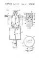
- FIG. 1is a side sectional view of a coating apparatus including in the invention
- FIG. 2is a side sectional, enlarged view of a portion of the structure illustrated in FIG. 1;
- FIG. 3is a front view of a substrate in accordance with the invention in combination with a substrate holding structure in accordance with the invention
- FIGS. 4, 5, 6 and 7are side sectional, enlarged views of four additional embodiments of the invention.
- FIG. 8is a plan view of another embodiment of the apparatus.
- FIG. 9is an enlarged plan view of a portion of FIG. 8.
- FIG. 10is a sectional view taken on line 10--10 of FIG. 9.
- the inventionis described in combination with a cathode sputtering structure in connection with FIG. 1. It is to be understood, however, that the invention is applicable to other types of vacuum coating systems and is not restricted to cathode sputtering. The invention is also applicable to other types of substrate processing such as sputter etching.
- substrate 11preferably fabricated as a rigid non-magnetic preferably aluminum disc, is vertically translated by blade 14 between vacuum handling chamber 12 and vacuum sputter coating chamber 13. While substrate 11 is coated, blade 14 holds the substrate on edge so that parallel, planar faces 15 and 16 (FIG. 2) of the substrate are vertically disposed.
- substrate 11By positioning substrate 11 so that faces 15 and 16 are vertically disposed, settling of particulates, having a tendency to be generated in vacuum chamber 13 during the sputtering operation, is minimized so that surfaces 15 and 16 remain relatively free of contaminants.
- targets 17 and 18form part of a cathode electrode.
- targets 17 and 18are fabricated of a magnetic material which, when deposited on substrate 11, is capable of storing magnetic information.
- envelope 19 of chamber 13serves as an anode electrode.
- DC source 20maintains targets 17 and 18 at a relatively high, negative DC voltage, while metal envelope 19 is grounded.
- An inert gas, typically argon,is supplied from a suitable source 21 to the interior of chamber 13, that is evacuated by vacuum source 22.
- blade 14is lowered, to return substrate 11 to handling chamber 12. After substrate 11 has been returned to handling chamber 12, it is removed from blade 14 and transported, by suitable means (not shown) to another vacuum coating station or to an unloading vacuum lock station. The entire time while substrate 11 is held by blade 14, the substrate is held on edge, so that faces 15 and 16 are vertically disposed.
- actuating cylinder 27preferably driven by a pneumatic source, is provided. Cylinder 27 drives piston 28, having an upper horizontal face to which platform 29 is secured. Platform 29 carries blade 14.
- the edge 31includes groove 32.
- Groove 32is concentric with and extends completely around peripheral edge 31.
- Groove 32has a generally triangular cross-section (FIG. 2), with generally vertical, slightly sloping planar surfaces 33 and 34 that meet at root 32' of groove 32. Root 32', at the intersection of surfaces 33 and 34, is rounded to facilitate manufacture of groove 32. The angle between surfaces 33 and 34 is typically 60°.
- groove 32For a typical magnetic disc having a substrate 11 with a thickness between faces 15 and 16 of approximately 1.9 mm, groove 32 has a radial depth of approximately 1.0 mm. The apex of root 32' is equispaced between faces 15 and 16.
- Groove 32has an opening in edge 31, between faces 15 and 16, of approximately 1.2 mm. In accordance with the invention it has been found that even though the substrate is relatively thin, there is adequate thickness on both sides of the groove 32 along edge 31 to provide adequate strength between surface 33 and face 15, as well as between face 34 and face 16.
- blade 14is configured so that the tip thereof corresponds in cross-sectional shape with the cross-sectional shape of groove 32.
- Blade 14includes parallel, vertically extending faces 35 and 36, which extend upwardly from platform 29. At the upper ends of faces 35 and 36, horizontal shoulders 39 and 40 are provided. From the inner edges of shoulders 39 and 40 are upwardly extending knife edge segments 37 and 38 that are tapered toward each other so as to have a shape corresponding with surfaces 33 and 34. The dimensions and shape of edges 37 and 38 are such that the edges can fit into groove 32 between surfaces 33 and 34. Edges 37 and 38 are rounded at the ends thereof to define a circular edge 41 which enters the groove. Circular edge 41 has a radius (in side view, FIG.
- Edge 41has an approximately 90° angular extent (in side view), so that one quarter of the peripheral area of substrate 11 bears against edge 41 to provide substantial contact area between substrate 11 and blade 14.
- the angular extent of edge 41could be more or less than 90° but preferably not more than 180° so as not to project outwardly beyond the diameter of the substrate.
- substrate 11When groove 32 extends 360° around the periphery of edge 31, substrate 11 is orientation insensitive. In other words, it is not necessary for substrate 11 to have any particular angular orientation when it is engaged by blade 14. Because there are no obstructions between targets 17 and 18 or the coating material generated thereby and faces 15 and 16, coatings 24 and 25 are deposited across the faces of substrate 11, completely to edge 31, and the thicknesses of coatings 24 and 25 at edge 31 can be the same as the thicknesses of the coatings at other portions of substrate 11 where coating material is deposited.
- the groove 32can extend along only an edge portion of the substrate which forms a circular arc slightly larger than the width of blade 14 as viewed in FIG. 3.
- the center portion of the upper edge of blade 14(as viewed in FIG. 3) can be recessed downwardly (for example across the center one third of the total width of the blade) so as not to engage the substrate when the substrate is supported by the two upwardly projecting outer portions of the blade.
- the important considerationis that the blade engage the substrate at two locations on opposite sides of the vertical diameter of the substrate and significantly above the bottom of the substrate to hold the substrate against tilting. In such an arrangement the substrate can have two spaced groove portions to receive the two spaced outer projections on the blade.
- Hard magnetic disc substratessuch as disc 11 are normally made with a centrally located hole as shown at 43 in FIG. 3.
- the outside diameter of the discsranges from about 50 mm to about 355 mm.
- FIGS. 4-7wherein alternate configurations for blade 14 and groove 32 are illustrated.
- the bladehas side walls that extend into groove 32 such that the wall length is sufficiently great to preclude shadowing of faces 15 and 16.
- groove 32preferably has a depth of approximately 1.0 mm and extends completely around the periphery of edge 31.
- groove 32has a cross-section similar to that of a pentagon, including walls 42 and 43, both of which are parallel to each other and faces 15 and 16.
- Parallel walls 42 and 43intersect sloping walls 44 and 45, respectively.
- Walls 44 and 45intersect at circular cross-sectioned root 46 of groove 32.
- the angle between walls 44 and 45is approximately 45°, a result achieved because of the geometry wherein walls 42 and 43 extend approximately 0.5 mm radially into substrate 11.
- the end of blade 14 which engages groove 32 to support and hold substrate 11has a pentagonal shape including sloping end walls 47 and 48, each of which is approximately as long as walls 44 and 45; walls 47 and 48 are joined together by rounded tip 49, which conforms with rounded root 46. Sloping walls 47 and 48 extend from parallel walls 51 and 52, having a length approximately twice the length of walls 42 and 43. Thereby, walls 51 and 52 extend from sloping shoulders 53 and 54, respectively, such that the shoulders are spaced from and do not shadow faces 15 and 16 of disc substrate 11.
- groove 32includes sloping walls 55 and 56 which start at edge 31 and taper toward each other as they extend radially toward the center of disc substrate 11.
- Walls 55 and 56extend radially of disc 11 for approximately 0.5 mm, at which point they intersect walls 57 and 58, that are parallel with each other and with faces 15 and 16.
- Walls 57 and 58extend radially of disc substrate 11 until they intersect circular root segment 59.
- the disc substrate 11 of FIG. 5is supported by a blade including a pair of elongated walls 61 and 62, spaced from each other by slightly less than the spacing between walls 57 and 58.
- Walls 61 and 62have a length in excess of the distance between edge 31 and root 59, to preclude a shadow effect on faces 15 and 16.
- walls 61 and 62extend from sloping shoulders 63 of blade 14.
- Walls 61 and 62are connected by a circular tip 60.
- the relatively wide mouth on edge 31, between sloping walls 55 and 56,allows greater tolerance in the positioning of blade 14 relative to substrate 11 across the width of the substrate between faces 15 and 16 (for insertion of the blade into groove 32).
- groove 32has a semi-circular cross-section with a perimeter 64 having a diameter on edge 31.
- the semi-circlehas a point of tangency across the width of disc 11 at a point equidistant from faces 15 and 16; similarly, the grooves in all other embodiments are preferably centered between the opposite faces of substrate 11.
- the semi-circular groove 64is easier to fabricate than the grooves of the other embodiments but is likely to be less stable in holding the substrate than the other embodiments.
- blade 14is configured to have a semi-circular periphery 65, having a radius approximately equal to, but slightly less than, the radius of perimeter 64.
- Semi-circular perimeter 65extends from vertically extending walls 66 and 67 at a point of tangency between the semi-circular perimeter and the vertical walls. Walls 66 and 67 have a length sufficient to prevent a shadow effect of material on faces 15 and 16 adjacent edge 31. Walls 66 and 67 extend from shoulders 68.
- groove 32is formed as two parallel walls 71 and 72 which extend from edge 31 and are parallel to each other, as well as faces 15 and 16.
- Walls 71 and 72extend approximately 0.5 mm radially toward the center of disc 11, at which point they intersect semicircular wall segment 73, where the diameter of the wall segment is such that it intersects walls 71 and 72 diametrically opposite points of tangency.
- Blade 14has an end which conforms roughly with the groove illustrated in FIG. 7.
- the end of blade 14has a cross-section with a semi-circular perimeter 74 having a diameter slightly less than the diameter of peripheral wall segment 73.
- the perimeterintersects vertically extending, parallel walls 75 and 76, having a spacing between them slightly less than the spacing between walls 71 and 72.
- Walls 75 and 76have a length sufficiently in excess of the length of walls 71 and 72 to preclude casting a shadow on faces 15 and 16 at the intersection thereof with edge 31.
- Walls 75 and 76extend from sloping shoulders 77 of blade 14.
- FIGS. 5-7the tip edge of the blade will engage the root of groove 32 when the substrate is supported vertically on the blade. Such engagement is not required for FIGS. 2, 4 and 10.
- substrate 11can be formed as a cast aluminum or other non-magnetic metal wherein the desired shape is achieved by proper formation of the casting dies.
- mechanical meanssuch as saws or mills, can be used to form grooves 32 in edges 31.
- FIGS. 8, 9 and 10Another embodiment of the invention is shown in FIGS. 8, 9 and 10.
- the holding structureis so designed that substrate 11 is held and/or transported by a plurality of supporting blades.
- the holding structurecan support a single substrate, or a plurality of substrates when the holding structure is in the form of an enlarged platen 50 (FIG. 8).
- the platencould be of a size to support only one substrate.
- a support structuresuch as platen 50 is provided with one or more apertures 52.
- a plurality of supporting blades 54, 55, and 56are attached to the platten in spaced fashion around aperture 52.
- Blades 54 and 55are stationary and blade 56 is moveable toward and away from edge 31 of the substrate.
- Blades 54 and 55are preferably spaced part such that the centerlines through each of them intersect to form at an angle of about 120° or less, but preferably not less than about 90°.
- Moveable blade 56is preferably located on the diameter of aperture 52 which bisects the angle between stationary blades 54 and 55.
- blades 54 and 55could be replaced by a single stationary blade. In which case the single blade is preferably centered on the same diameter on which moveable blade 56 is centered, and the combined length of circular contact between the substrate and the two blades must be sufficient to hold the substrate securely in a fixed plane.
- blade 56has an integral arm 58 which is rigidly attached to a shaft 60 which is received in a bearing bore in platen 50 and is held against axial motion as by nut 62.
- a knurled turn knob 64is rigidly attached to arm 58 concentric with the axis of shaft 60.
- the criteria for the arrangementis that the blade 56 is maintained in a fixed plane as it moves about the axis of shaft 60 during substrate loading and unloading operations.
- the arrangementmay be such that the arm 58 bears rotatably against recessed wall 66 of the platen, or against an intervening washer, and that nut 62 or equivalent bears rotatably against the opposite wall of the platen and is designed so that after it is threaded onto shaft 60 it is prevented from rotating relative to the shaft during rotation of arm 58 about the axis of the shaft. Also, it is necessary that when arm 58 is rotated to a position in which blade 56 contacts groove 68 (FIG. 10) in the edge of substrate 11, the blade will be prevented from movement out of such contact until it is desired to unload the substrate. As shown schematically in FIG.
- the arrangement of spring 70is preferably also such that when arm 58 is rotated clockwise to the retracted position (which enables insertion or removal of the substrate) the spring will cause it to remain there until knob 64 is rotated counterclockwise to move blade 56 back into engagement with a substrate.
- FIG. 10The cross-section shape of the groove 68 and the end of each of the blades 54-56 is shown in FIG. 10 as being a knife edge taper for the blades and a matching taper for the groove walls, similar to FIG. 2 but without shoulders 39 and 40.
- the shape for the groove and blades for the embodiment of FIGS. 8-10can be the same as any shown in FIGS. 2 and 4-7.
- the groove shape of FIG. 6will not suffer from the instability which may be experienced when used with a single blade.
- the substrate-loading procedure for the embodiment of FIGS. 8-10is that an operator rotates knob 64 to its retracted position in which the inner edge of blade 56 is moved outward far enough for the operator to position a substrate 11 such that blades 54 and 55 are received in groove 68. Then the operator rotates knob 64 to insert blade 56 into the groove. For unloading, the operator turns knob 64 to fully withdraw blade 56 and then removes the substrate from blades 54 and 55.
- the operatorcan hold the blade during loading and unloading either by grasping it around hole 43 by placing one finger through the hole and another finger on the opposite face of the substrate, or by grasping the substrate around its periphery. In the later case the aperture 52 must be large enough (or indented) to accomodate the operator's fingers.
- the operatormay use spring type tweezers to grip either the inner or outer periphery of the substrate.
- platen 50After platen 50 is loaded with one or more substrates, it can be held stationary in, or moved through, a vacuum chamber in vertical, horizontal or other angular orientation so the one or more substrates can be coated from one or more coating sources located on one or both sides of the platen.
- the blades 54-56 and the moving mechanism for blade 56can be mounted on the face of an unapertured platen 50. Such an arrangement would still use the same circular orientation of the blades as shown in FIG. 9, and the same spaced location as shown in FIG. 8 for the various three-blade sets which each hold one substrate.
Landscapes
- Chemical & Material Sciences (AREA)
- Chemical Kinetics & Catalysis (AREA)
- Engineering & Computer Science (AREA)
- Materials Engineering (AREA)
- Mechanical Engineering (AREA)
- Metallurgy (AREA)
- Organic Chemistry (AREA)
- Manufacturing Of Magnetic Record Carriers (AREA)
- Magnetic Record Carriers (AREA)
Abstract
Description
Claims (6)
Priority Applications (2)
| Application Number | Priority Date | Filing Date | Title |
|---|---|---|---|
| US06/548,124US4558388A (en) | 1983-11-02 | 1983-11-02 | Substrate and substrate holder |
| JP59218730AJPS60103520A (en) | 1983-11-02 | 1984-10-19 | Substrate and substrate holder |
Applications Claiming Priority (1)
| Application Number | Priority Date | Filing Date | Title |
|---|---|---|---|
| US06/548,124US4558388A (en) | 1983-11-02 | 1983-11-02 | Substrate and substrate holder |
Publications (1)
| Publication Number | Publication Date |
|---|---|
| US4558388Atrue US4558388A (en) | 1985-12-10 |
Family
ID=24187523
Family Applications (1)
| Application Number | Title | Priority Date | Filing Date |
|---|---|---|---|
| US06/548,124Expired - Fee RelatedUS4558388A (en) | 1983-11-02 | 1983-11-02 | Substrate and substrate holder |
Country Status (2)
| Country | Link |
|---|---|
| US (1) | US4558388A (en) |
| JP (1) | JPS60103520A (en) |
Cited By (35)
| Publication number | Priority date | Publication date | Assignee | Title |
|---|---|---|---|---|
| WO1986006753A1 (en)* | 1985-05-09 | 1986-11-20 | Seagate Technology | IN-lINE DISK SPUTTERING SYSTEM |
| US4634512A (en)* | 1984-08-21 | 1987-01-06 | Komag, Inc. | Disk and plug |
| EP0235731A1 (en)* | 1986-02-26 | 1987-09-09 | BASF Aktiengesellschaft | Device for supporting work pieces on substrate holders |
| US4701251A (en)* | 1986-02-03 | 1987-10-20 | Bvt Limited | Apparatus for sputter coating discs |
| US4749465A (en)* | 1985-05-09 | 1988-06-07 | Seagate Technology | In-line disk sputtering system |
| US4790921A (en)* | 1984-10-12 | 1988-12-13 | Hewlett-Packard Company | Planetary substrate carrier method and apparatus |
| US4834855A (en)* | 1985-05-02 | 1989-05-30 | Hewlett-Packard Company | Method for sputter depositing thin films |
| EP0222459A3 (en)* | 1985-11-15 | 1989-08-23 | Komag, Inc. | Robotic disk handler system and method |
| US4909185A (en)* | 1988-02-03 | 1990-03-20 | Weiss Scientific Glass Blowing Co. | Cantilever and cold zone assembly for loading and unloading an oven |
| US4938858A (en)* | 1989-04-14 | 1990-07-03 | Leybold Aktiengesellschaft | Cathode sputtering system |
| US5091212A (en)* | 1988-12-19 | 1992-02-25 | Murata Manufacturing Co., Ltd. | Method and apparatus for forming electrode on electronic component |
| US5228968A (en)* | 1991-12-11 | 1993-07-20 | Leybold Aktiengesellschaft | Cathode sputtering system with axial gas distribution |
| US5244555A (en)* | 1991-11-27 | 1993-09-14 | Komag, Inc. | Floating pocket memory disk carrier, memory disk and method |
| US5356522A (en)* | 1992-02-18 | 1994-10-18 | Hmt Technology Corporation | Method for manufacturing thin-film medium with chromium underlayer gradient |
| US5514259A (en)* | 1989-12-07 | 1996-05-07 | Casio Computer Co., Ltd. | Sputtering apparatus |
| US5516545A (en)* | 1991-03-26 | 1996-05-14 | Sandock; Leonard R. | Coating processes and apparatus |
| WO1996022405A1 (en)* | 1995-01-17 | 1996-07-25 | Hmt Technology Corporation | Disc-handling apparatus |
| US5576058A (en)* | 1994-03-18 | 1996-11-19 | Sandvik Ab | Batch loading system for CVD |
| US5683561A (en)* | 1991-04-04 | 1997-11-04 | Conner Peripherals, Inc. | Apparatus and method for high throughput sputtering |
| WO1998014631A1 (en)* | 1996-10-02 | 1998-04-09 | Intevac, Inc. | Methods and apparatus for sputtering with rotating magnet sputter sources |
| US5753091A (en)* | 1993-05-05 | 1998-05-19 | Hoechst Aktiengesellschaft | Carrier palette for substrates of optical storage media |
| US5753089A (en)* | 1995-06-28 | 1998-05-19 | Balzers Aktiengesellschaft | Sputter coating station |
| US5792272A (en)* | 1995-07-10 | 1998-08-11 | Watkins-Johnson Company | Plasma enhanced chemical processing reactor and method |
| US5976255A (en)* | 1997-09-20 | 1999-11-02 | Anelva Corporation | Substrate holder for reducing non-uniform film characteristics resulting from support structures |
| US6183615B1 (en) | 1992-06-26 | 2001-02-06 | Tokyo Electron Limited | Transport system for wafer processing line |
| US6250374B1 (en) | 1998-01-12 | 2001-06-26 | Anelva Corporation | Apparatus and method for treating substrates |
| US20020000198A1 (en)* | 1997-05-29 | 2002-01-03 | Applied Materials, Inc. | The dome: shape and temperature controlled surfaces |
| US6497799B1 (en) | 2000-04-14 | 2002-12-24 | Seagate Technology Llc | Method and apparatus for sputter deposition of multilayer films |
| US6567240B2 (en)* | 2001-02-26 | 2003-05-20 | International Business Machines Corporation | Disk drive platter using sputter shadows thereon for determining orientation thereof |
| US6605195B2 (en) | 2000-04-14 | 2003-08-12 | Seagate Technology Llc | Multi-layer deposition process using four ring sputter sources |
| US20090125109A1 (en)* | 2005-01-24 | 2009-05-14 | Danfoss A/S | Method for coating an object |
| US20100251960A1 (en)* | 2007-12-14 | 2010-10-07 | Ulvac, Inc. | Chamber and film forming apparatus |
| CN101899643A (en)* | 2009-05-28 | 2010-12-01 | 西部数据传媒公司 | The magnetic particle trapper that is used for disk sputtering system |
| US20120199477A1 (en)* | 2009-08-26 | 2012-08-09 | Canon Anelva Corporation | Film forming apparatus |
| US11643751B2 (en) | 2020-03-10 | 2023-05-09 | Matrix Sensors, Inc. | Apparatus and method for producing a crystalline film on a substrate surface |
Families Citing this family (1)
| Publication number | Priority date | Publication date | Assignee | Title |
|---|---|---|---|---|
| JPH0190167U (en)* | 1987-12-02 | 1989-06-14 |
Citations (8)
| Publication number | Priority date | Publication date | Assignee | Title |
|---|---|---|---|---|
| US1229428A (en)* | 1917-03-03 | 1917-06-12 | Thoralf Fabritius | Golf-ball hanger. |
| US1945572A (en)* | 1932-06-04 | 1934-02-06 | Sandbrook Arthur | Screen holder |
| US2349908A (en)* | 1941-03-03 | 1944-05-30 | Int Harvester Co | Holder for deplating articles |
| US3396696A (en)* | 1966-10-06 | 1968-08-13 | Ralph F. Becker | Lens turner for high vacuum evaporators |
| US3516386A (en)* | 1965-07-16 | 1970-06-23 | Boeing Co | Thin film deposition fixture |
| US3808079A (en)* | 1969-12-29 | 1974-04-30 | Fuji Photo Film Co Ltd | Method of making a magnetic disc |
| US3874525A (en)* | 1973-06-29 | 1975-04-01 | Ibm | Method and apparatus for handling workpieces |
| US4311427A (en)* | 1979-12-21 | 1982-01-19 | Varian Associates, Inc. | Wafer transfer system |
- 1983
- 1983-11-02USUS06/548,124patent/US4558388A/ennot_activeExpired - Fee Related
- 1984
- 1984-10-19JPJP59218730Apatent/JPS60103520A/enactivePending
Patent Citations (8)
| Publication number | Priority date | Publication date | Assignee | Title |
|---|---|---|---|---|
| US1229428A (en)* | 1917-03-03 | 1917-06-12 | Thoralf Fabritius | Golf-ball hanger. |
| US1945572A (en)* | 1932-06-04 | 1934-02-06 | Sandbrook Arthur | Screen holder |
| US2349908A (en)* | 1941-03-03 | 1944-05-30 | Int Harvester Co | Holder for deplating articles |
| US3516386A (en)* | 1965-07-16 | 1970-06-23 | Boeing Co | Thin film deposition fixture |
| US3396696A (en)* | 1966-10-06 | 1968-08-13 | Ralph F. Becker | Lens turner for high vacuum evaporators |
| US3808079A (en)* | 1969-12-29 | 1974-04-30 | Fuji Photo Film Co Ltd | Method of making a magnetic disc |
| US3874525A (en)* | 1973-06-29 | 1975-04-01 | Ibm | Method and apparatus for handling workpieces |
| US4311427A (en)* | 1979-12-21 | 1982-01-19 | Varian Associates, Inc. | Wafer transfer system |
Non-Patent Citations (1)
| Title |
|---|
| U.S. application Ser. No. 515,247; Boys; Donald R. et al., Disk or Wafer Handling and Coating System, filed 07/19/83.* |
Cited By (45)
| Publication number | Priority date | Publication date | Assignee | Title |
|---|---|---|---|---|
| US4634512A (en)* | 1984-08-21 | 1987-01-06 | Komag, Inc. | Disk and plug |
| US4790921A (en)* | 1984-10-12 | 1988-12-13 | Hewlett-Packard Company | Planetary substrate carrier method and apparatus |
| US4834855A (en)* | 1985-05-02 | 1989-05-30 | Hewlett-Packard Company | Method for sputter depositing thin films |
| WO1986006753A1 (en)* | 1985-05-09 | 1986-11-20 | Seagate Technology | IN-lINE DISK SPUTTERING SYSTEM |
| US4749465A (en)* | 1985-05-09 | 1988-06-07 | Seagate Technology | In-line disk sputtering system |
| EP0222459A3 (en)* | 1985-11-15 | 1989-08-23 | Komag, Inc. | Robotic disk handler system and method |
| EP0222458A3 (en)* | 1985-11-15 | 1989-08-16 | Komag, Inc. | Disk and plug |
| US4701251A (en)* | 1986-02-03 | 1987-10-20 | Bvt Limited | Apparatus for sputter coating discs |
| EP0235731A1 (en)* | 1986-02-26 | 1987-09-09 | BASF Aktiengesellschaft | Device for supporting work pieces on substrate holders |
| US4909185A (en)* | 1988-02-03 | 1990-03-20 | Weiss Scientific Glass Blowing Co. | Cantilever and cold zone assembly for loading and unloading an oven |
| US5091212A (en)* | 1988-12-19 | 1992-02-25 | Murata Manufacturing Co., Ltd. | Method and apparatus for forming electrode on electronic component |
| US4938858A (en)* | 1989-04-14 | 1990-07-03 | Leybold Aktiengesellschaft | Cathode sputtering system |
| US5514259A (en)* | 1989-12-07 | 1996-05-07 | Casio Computer Co., Ltd. | Sputtering apparatus |
| US5516545A (en)* | 1991-03-26 | 1996-05-14 | Sandock; Leonard R. | Coating processes and apparatus |
| US5683561A (en)* | 1991-04-04 | 1997-11-04 | Conner Peripherals, Inc. | Apparatus and method for high throughput sputtering |
| US5814196A (en)* | 1991-04-04 | 1998-09-29 | Conner Peripherals, Inc. | Apparatus and method for high throughput sputtering |
| US5244555A (en)* | 1991-11-27 | 1993-09-14 | Komag, Inc. | Floating pocket memory disk carrier, memory disk and method |
| US5228968A (en)* | 1991-12-11 | 1993-07-20 | Leybold Aktiengesellschaft | Cathode sputtering system with axial gas distribution |
| US5356522A (en)* | 1992-02-18 | 1994-10-18 | Hmt Technology Corporation | Method for manufacturing thin-film medium with chromium underlayer gradient |
| US6183615B1 (en) | 1992-06-26 | 2001-02-06 | Tokyo Electron Limited | Transport system for wafer processing line |
| US5753091A (en)* | 1993-05-05 | 1998-05-19 | Hoechst Aktiengesellschaft | Carrier palette for substrates of optical storage media |
| US5576058A (en)* | 1994-03-18 | 1996-11-19 | Sandvik Ab | Batch loading system for CVD |
| US5759621A (en)* | 1994-03-18 | 1998-06-02 | Sandvik Ab | Batch loading system for CVD |
| WO1996022405A1 (en)* | 1995-01-17 | 1996-07-25 | Hmt Technology Corporation | Disc-handling apparatus |
| US5753089A (en)* | 1995-06-28 | 1998-05-19 | Balzers Aktiengesellschaft | Sputter coating station |
| US5792272A (en)* | 1995-07-10 | 1998-08-11 | Watkins-Johnson Company | Plasma enhanced chemical processing reactor and method |
| US6001267A (en)* | 1995-07-10 | 1999-12-14 | Watkins-Johnson Company | Plasma enchanced chemical method |
| US6178918B1 (en) | 1995-07-10 | 2001-01-30 | Applied Materials, Inc. | Plasma enhanced chemical processing reactor |
| US5830327A (en)* | 1996-10-02 | 1998-11-03 | Intevac, Inc. | Methods and apparatus for sputtering with rotating magnet sputter sources |
| WO1998014631A1 (en)* | 1996-10-02 | 1998-04-09 | Intevac, Inc. | Methods and apparatus for sputtering with rotating magnet sputter sources |
| US20020000198A1 (en)* | 1997-05-29 | 2002-01-03 | Applied Materials, Inc. | The dome: shape and temperature controlled surfaces |
| US5976255A (en)* | 1997-09-20 | 1999-11-02 | Anelva Corporation | Substrate holder for reducing non-uniform film characteristics resulting from support structures |
| US6250374B1 (en) | 1998-01-12 | 2001-06-26 | Anelva Corporation | Apparatus and method for treating substrates |
| US6605195B2 (en) | 2000-04-14 | 2003-08-12 | Seagate Technology Llc | Multi-layer deposition process using four ring sputter sources |
| US6497799B1 (en) | 2000-04-14 | 2002-12-24 | Seagate Technology Llc | Method and apparatus for sputter deposition of multilayer films |
| US6567240B2 (en)* | 2001-02-26 | 2003-05-20 | International Business Machines Corporation | Disk drive platter using sputter shadows thereon for determining orientation thereof |
| US20090125109A1 (en)* | 2005-01-24 | 2009-05-14 | Danfoss A/S | Method for coating an object |
| US8535751B2 (en) | 2005-01-24 | 2013-09-17 | Tantaline A/S | Method for coating an object |
| US20100251960A1 (en)* | 2007-12-14 | 2010-10-07 | Ulvac, Inc. | Chamber and film forming apparatus |
| US8677925B2 (en)* | 2007-12-14 | 2014-03-25 | Ulvac, Inc. | Chamber and film forming apparatus |
| CN101899643A (en)* | 2009-05-28 | 2010-12-01 | 西部数据传媒公司 | The magnetic particle trapper that is used for disk sputtering system |
| US20100300875A1 (en)* | 2009-05-28 | 2010-12-02 | Wd Media, Inc. | Magnetic particle trapper for a disk sputtering system |
| US8101054B2 (en) | 2009-05-28 | 2012-01-24 | Wd Media, Inc. | Magnetic particle trapper for a disk sputtering system |
| US20120199477A1 (en)* | 2009-08-26 | 2012-08-09 | Canon Anelva Corporation | Film forming apparatus |
| US11643751B2 (en) | 2020-03-10 | 2023-05-09 | Matrix Sensors, Inc. | Apparatus and method for producing a crystalline film on a substrate surface |
Also Published As
| Publication number | Publication date |
|---|---|
| JPS60103520A (en) | 1985-06-07 |
Similar Documents
| Publication | Publication Date | Title |
|---|---|---|
| US4558388A (en) | Substrate and substrate holder | |
| US5922176A (en) | Spark eliminating sputtering target and method for using and making same | |
| US5024747A (en) | Wafer coating system | |
| US5114556A (en) | Deposition apparatus and method for enhancing step coverage and planarization on semiconductor wafers | |
| US4756815A (en) | Wafer coating system | |
| US6086735A (en) | Contoured sputtering target | |
| WO2019221972A1 (en) | Pre-clean chamber with integrated shutter garage | |
| KR102699890B1 (en) | Two-piece shutter disc assembly with self-centering feature | |
| JPH036990B2 (en) | ||
| JPH05259258A (en) | Removable shutter of semiconductor processing chamber | |
| US6042706A (en) | Ionized PVD source to produce uniform low-particle deposition | |
| US20060054494A1 (en) | Physical vapor deposition apparatus for depositing thin multilayer films and methods of depositing such films | |
| US20050072668A1 (en) | Sputter target having modified surface texture | |
| CA2611345A1 (en) | Sputtering target with slow-sputter layer under target material | |
| JPH11503793A (en) | Mechanically mounted sputtering target and adapter | |
| KR930008341B1 (en) | Device for transferring a workpiece into and out of a vacuum chamber | |
| CN100540726C (en) | Modular units for coated surfaces | |
| US5089110A (en) | Data storage disk and plug | |
| JP3498950B2 (en) | Multi target equipment for sputtering | |
| CN117178340A (en) | Sputtering units for coating 3D objects | |
| EP0634779A1 (en) | Collimation chamber with rotatable pedestal | |
| KR20210116245A (en) | Sputtering apparatus | |
| US20190378699A1 (en) | Methods and apparatus for magnetron assemblies in semiconductor process chambers | |
| JPH02250963A (en) | Sputtering device | |
| JPS621229Y2 (en) |
Legal Events
| Date | Code | Title | Description |
|---|---|---|---|
| AS | Assignment | Owner name:VARIAN ASSOCIATES, INC., PALO ALTO, CA. A DE CORP. Free format text:ASSIGNMENT OF ASSIGNORS INTEREST.;ASSIGNOR:GRAVES, WALTER E. JR.;REEL/FRAME:004234/0986 Effective date:19831101 | |
| FEPP | Fee payment procedure | Free format text:PAYOR NUMBER ASSIGNED (ORIGINAL EVENT CODE: ASPN); ENTITY STATUS OF PATENT OWNER: LARGE ENTITY | |
| FPAY | Fee payment | Year of fee payment:4 | |
| AS | Assignment | Owner name:INTEVAC, INC. Free format text:CHANGE OF NAME;ASSIGNOR:DKP ELECTRONICS, A CORPORATION OF CA;REEL/FRAME:005805/0265 Effective date:19910219 Owner name:DKP, A CORPORATION OF CA, CALIFORNIA Free format text:ASSIGNMENT OF ASSIGNORS INTEREST, EFFECTIVE 2/15/1991.;ASSIGNOR:VARIAN ASSOCIATES INC., A CORPORATION OF DE;REEL/FRAME:005805/0259 Effective date:19910331 | |
| REMI | Maintenance fee reminder mailed | ||
| AS | Assignment | Owner name:SILICON VALLEY BANK, CALIFORNIA Free format text:SECURITY INTEREST;ASSIGNOR:INTEVAC, INC.;REEL/FRAME:006747/0087 Effective date:19930708 | |
| LAPS | Lapse for failure to pay maintenance fees | ||
| FP | Lapsed due to failure to pay maintenance fee | Effective date:19931212 | |
| STCH | Information on status: patent discontinuation | Free format text:PATENT EXPIRED DUE TO NONPAYMENT OF MAINTENANCE FEES UNDER 37 CFR 1.362 |