US4558172A - Wall recess cable connector permitting simplified innerconnection and limiting protruding cables - Google Patents
Wall recess cable connector permitting simplified innerconnection and limiting protruding cablesDownload PDFInfo
- Publication number
- US4558172A US4558172AUS06/521,448US52144883AUS4558172AUS 4558172 AUS4558172 AUS 4558172AUS 52144883 AUS52144883 AUS 52144883AUS 4558172 AUS4558172 AUS 4558172A
- Authority
- US
- United States
- Prior art keywords
- wall
- coaxial
- connector
- assembly
- chamber
- Prior art date
- Legal status (The legal status is an assumption and is not a legal conclusion. Google has not performed a legal analysis and makes no representation as to the accuracy of the status listed.)
- Expired - Lifetime
Links
- 238000012986modificationMethods0.000description6
- 230000004048modificationEffects0.000description6
- 230000005540biological transmissionEffects0.000description1
- 230000009977dual effectEffects0.000description1
- 239000003063flame retardantSubstances0.000description1
- 230000002452interceptive effectEffects0.000description1
- 239000000463materialSubstances0.000description1
Images

Classifications
- H—ELECTRICITY
- H01—ELECTRIC ELEMENTS
- H01R—ELECTRICALLY-CONDUCTIVE CONNECTIONS; STRUCTURAL ASSOCIATIONS OF A PLURALITY OF MUTUALLY-INSULATED ELECTRICAL CONNECTING ELEMENTS; COUPLING DEVICES; CURRENT COLLECTORS
- H01R13/00—Details of coupling devices of the kinds covered by groups H01R12/70 or H01R24/00 - H01R33/00
- H01R13/73—Means for mounting coupling parts to apparatus or structures, e.g. to a wall
- H—ELECTRICITY
- H01—ELECTRIC ELEMENTS
- H01R—ELECTRICALLY-CONDUCTIVE CONNECTIONS; STRUCTURAL ASSOCIATIONS OF A PLURALITY OF MUTUALLY-INSULATED ELECTRICAL CONNECTING ELEMENTS; COUPLING DEVICES; CURRENT COLLECTORS
- H01R2103/00—Two poles
- H—ELECTRICITY
- H01—ELECTRIC ELEMENTS
- H01R—ELECTRICALLY-CONDUCTIVE CONNECTIONS; STRUCTURAL ASSOCIATIONS OF A PLURALITY OF MUTUALLY-INSULATED ELECTRICAL CONNECTING ELEMENTS; COUPLING DEVICES; CURRENT COLLECTORS
- H01R24/00—Two-part coupling devices, or either of their cooperating parts, characterised by their overall structure
- H01R24/38—Two-part coupling devices, or either of their cooperating parts, characterised by their overall structure having concentrically or coaxially arranged contacts
- H01R24/40—Two-part coupling devices, or either of their cooperating parts, characterised by their overall structure having concentrically or coaxially arranged contacts specially adapted for high frequency
Definitions
- This inventionrelates to wiring for data transmission, such as between a terminal and a computer central processing unit, between terminals, or between two or more central processing units of a computer.
- wiring for data transmissionsuch as between a terminal and a computer central processing unit, between terminals, or between two or more central processing units of a computer.
- coaxial cable used for the interconnectionsrun within the walls and to have outlets in different rooms or offices.
- the assembly of the present inventionallows for recessed interconnection, for essentially flush mounting, and for easy connection and disconnection. Perhaps most importantly, it permits the coaxial cable to leave the connection area essentially flush with the wall and not protruding so as to interfere with furniture.
- a flush-type, wall-mounted coaxial connector assemblymade up of a wall plate with an inwardly recessed chamber to receive and interconnect the cables.
- the recessed chamberis of sufficient size to permit finger access for connecting and disconnecting the cable and is deep and wide enough so that the cable may bend and be essentially flush with the wall by the time it leaves the recessed chamber.
- the connectoritself is not on the back wall of the recess chamber, but is on one of the side walls; and the side wall is at such an angle as to permit the cable to readily flex sufficiently so that it leaves the recess essentially flush with the wall.
- a side wall at a slightly obtuse angle relative to the base plateis best.
- the recessed chambermay provide for more than one coaxial cable connector. It may also include a single external connector and a multiposition lockout switch within the recessed chamber for interconnecting that cable with any desired other cable.
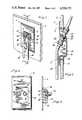
- FIG. 1is a perspective view of the wall mounting assembly showing two connectors located on one angularly positioned side wall of its chamber and showing two coaxial cables extending from the chamber substantially parallel to the wall surface.
- FIG. 2is a section on line 2--2 of FIG. 1 showing the interconnection of one cable with a coaxial cable running within the walls of the building. It should be noted that the cable running within the room is proximate to and parallel with the wall.
- FIG. 3is a front elevation of a modification of the invention in which two connectors are mounted on the back wall of the recessed chamber.
- FIG. 4is a side elevation, partially broken away, of the assembly of FIG. 3.
- FIG. 5is a further modification of the unit using a single connector and a multi-position push button lock-out switch, allowing the user to elect which incoming coaxial cable will be used.
- FIG. 6is a section on line 6--6 of FIG. 5.
- FIG. 1show various forms of my flush-type, wall-mounted connector assembly for interconnection of the coaxial cables of small office computers and the like with coaxial cables prewired within the walls of a building.
- the assembly 1includes a face plate 2 and, as shown, is secured to office wall 3 with bolts or screws 4.
- Assembly 1is integrally molded to form face plate 2 and recessed chamber 8, the preferred material being ABS fire retardant plastic.
- the recessed chamber 8is generally centered in the assembly.
- Recessed chamber 8includes back wall 10, side walls 12, bottom wall 14, and top wall 16.
- back wall 10is recessed from but parallel to face plate 2.
- Side walls 12 and bottom wall 14are perpendicular to face plate 2, and top wall 16 is at an obtuse angle with respect to face plate 14.
- FIGS. 1 and 2show two coaxial connectors 20 utilizing, in this instance, bayonet type mounts.
- the connectorsare made up of standard hardware which includes two jacks 22, a bushing 24 and a securing nut 26 (note also FIG. 4.)
- Assembly 1is preferably secured to the wall by having bolt 4 pass through the wall and be threaded to mounting plate 6 (FIG. 2.)
- the connected coaxial cables 30enter the room and lead to the terminal or other unit being used. They are connected through coaxial connectors 22 to the coaxial cables 32 running inside the walls.
- Coaxial cable 30is normally 93 ohm (RG 62/U) or 75 ohm (RG 59/U) which, though it will flex and bend, has limits upon the extent to which it can bend.
- top wall 16relative to the depth of recessed chamber 8 and the distance between top wall 16 and bottom wall 14 should be such that the connected cable has room to flex sufficiently to leave chamber 8 running substantially parallel with and contiguous to wall 3. (As shown for example in FIGS. 1 and 2.)
- the depth of the recessed chamberis limited due to the limitation of internal wall space.
- Typical dimensions for a dual recessed assembly unitwould include a face plate measuring 2.75 by 4.50 inches with an opening of 15/8 by 2 inches and bottom and side walls with a depth of 5/8 inches.
- the assemblyitself is approximately 1/8 inch thick.
- the back wallwould be (internally) about 13/4 inch long with the top wall dimensioned accordingly and at an angle to the face plate of approximately 120 degrees. With this dimensioning and the use of a standard jack, the outer edge of the jack itself would be approximately flush with the plane of face plate 2, thus permitting coaxial cable 30, when connected, to flex sufficiently to be proximate to and parallel with the wall 3.
- This assemblyincludes a wall plate having an inwardly recessed chamber 8 for receiving and interconnecting coaxial cable 30 located within the room with coaxial cables 32 located within the wall; and the chamber 8 includes side walls 12, back wall 10, bottom wall 14 and top wall 16. These walls define a chamber space adequate to hold a coaxial connector 20 entirely within the recessed chamber 8 and to permit finger access for attaching cable 30 by use of its connector 34; and connector unit 20 is mounted in one of the walls of the recess so that the coaxial cables 30 can be readily connected and disconnected within the assembly without the connector extending beyond the assembly's outer surface.
- FIGS. 3 and 4disclose a modification of my coaxial connector assembly.
- coaxial connector 20is secured to and passes through the back wall 10 of the recessed chamber 8. Its outer end is within chamber 8 providing for a recessed fixture, but is not on an angular wall such as top wall 16. This provides the convenience of a recessed fixture with space for finger access for connection and disconnection. Since the connector is recessed from the plane of the face plate 2, the cable will not project into the room to the extent normally found in such structures, but it is not as effective in providing a path for coaxial cable 30 immediately proximate to the office wall 3 as is the former modification.
- FIGS. 5 and 6disclose a further modification adapted to permit a single coaxial cable to be interconnected with various coaxial cables within the wall.
- the assemblyis somewhat wider, with face plate 2 including a recessed chamber 8 of rectangular cross section.
- Chamber 8includes a single connector 20 mounted on bottom wall 14 and uses a multiposition lock-out switch 42 to interconnect connector 20 with the desired one of a series of coaxial cables 46 within the wall.
- the actuating buttons 40 for switch 42project through the bottom wall 14 and so are accessible to the user.
- Connectors 46 for the various internal coaxial cablesare held by a mounting bracket 50 secured to the back of the recessed chamber.
- Switch 42is connected with connector 20 through leads 44 and with internal connectors 46 through leads 48.
Landscapes
- Details Of Indoor Wiring (AREA)
Abstract
Description
Claims (3)
Priority Applications (2)
| Application Number | Priority Date | Filing Date | Title |
|---|---|---|---|
| US06/521,448US4558172A (en) | 1983-08-08 | 1983-08-08 | Wall recess cable connector permitting simplified innerconnection and limiting protruding cables |
| US06/776,758US4950840A (en) | 1983-08-08 | 1985-09-16 | Wall recess cable connector permitting simplified innerconnection and limiting protruding cables |
Applications Claiming Priority (1)
| Application Number | Priority Date | Filing Date | Title |
|---|---|---|---|
| US06/521,448US4558172A (en) | 1983-08-08 | 1983-08-08 | Wall recess cable connector permitting simplified innerconnection and limiting protruding cables |
Related Child Applications (1)
| Application Number | Title | Priority Date | Filing Date |
|---|---|---|---|
| US06/776,758DivisionUS4950840A (en) | 1983-08-08 | 1985-09-16 | Wall recess cable connector permitting simplified innerconnection and limiting protruding cables |
Publications (1)
| Publication Number | Publication Date |
|---|---|
| US4558172Atrue US4558172A (en) | 1985-12-10 |
Family
ID=24076772
Family Applications (1)
| Application Number | Title | Priority Date | Filing Date |
|---|---|---|---|
| US06/521,448Expired - LifetimeUS4558172A (en) | 1983-08-08 | 1983-08-08 | Wall recess cable connector permitting simplified innerconnection and limiting protruding cables |
Country Status (1)
| Country | Link |
|---|---|
| US (1) | US4558172A (en) |
Cited By (26)
| Publication number | Priority date | Publication date | Assignee | Title |
|---|---|---|---|---|
| USD286739S (en) | 1983-09-26 | 1986-11-18 | Svagstroms Montage HB | Protective cover for low voltage equipment |
| USD286740S (en) | 1983-09-26 | 1986-11-18 | Svagstroms Montage HB | Protective cover for low voltage equipment |
| US4669802A (en)* | 1986-03-26 | 1987-06-02 | Amp Incorporated | Outlet for optical fiber connectors |
| US4758687A (en)* | 1986-05-16 | 1988-07-19 | Deborah Ann Lathrop | Obliquely walled electrical box |
| US4922056A (en)* | 1988-02-10 | 1990-05-01 | Network Communications, Inc. | Surface mounted box |
| US5002502A (en)* | 1990-05-22 | 1991-03-26 | Hill Robert D | Satellite TV system to tuner receiver main cable array wall plate assembly |
| USD350727S (en) | 1992-11-13 | 1994-09-20 | Control Logic (Proprietary) Limited | Facia portion of an electrical socket |
| US5645449A (en)* | 1995-02-21 | 1997-07-08 | The Whitaker Corporation | Low profile mixed media information outlet |
| US5735714A (en)* | 1995-04-06 | 1998-04-07 | Ortronics Inc. | Information management outlet module and assembly providing protection to exposed cabling |
| WO1998018654A1 (en)* | 1996-10-26 | 1998-05-07 | Robert Bosch Gmbh | Radio receiver |
| RU2129748C1 (en)* | 1993-03-12 | 1999-04-27 | Эйти энд Ти Корп. | Electrical equipment safety box |
| US6175079B1 (en) | 1999-06-03 | 2001-01-16 | Tyco Electronics Corporation | Fiber optic cable management system |
| US6231380B1 (en)* | 1999-03-31 | 2001-05-15 | Adc Telecommunications, Inc. | Bulkhead connector system including angled adapter |
| USD443252S1 (en) | 2000-06-02 | 2001-06-05 | Corning Cable Systems Llc | Wall mount housing |
| US6250816B1 (en) | 1999-02-19 | 2001-06-26 | Tyco Electronics Corporation | Cable connector plate and method for interconnecting ends of fiber optic cable |
| US6353183B1 (en)* | 1996-05-23 | 2002-03-05 | The Siemon Company | Adapter plate for use with cable adapters |
| US6713679B2 (en)* | 2001-09-25 | 2004-03-30 | Hubbell Incorporated | Terminal pad for an insulator assembly |
| USD553475S1 (en)* | 2006-11-30 | 2007-10-23 | Data:)Comm Electronics, Inc. | Wall plate with angled edge internal nose |
| USD554475S1 (en)* | 2006-10-20 | 2007-11-06 | Data: ) Comm Electronics, Inc. | Wall plate having internal nose for electrical cable |
| US7371130B1 (en)* | 2006-08-17 | 2008-05-13 | Grant Michael F | Coaxial cable covering |
| US7554036B1 (en) | 2008-02-15 | 2009-06-30 | Decosta Thomas J | Sectional plate for wall port incorporating recessed scoop for wire management |
| US20090269011A1 (en)* | 2007-11-30 | 2009-10-29 | Jarrod Scadden | Hybrid fiber/copper connector system and method |
| US20130291740A1 (en)* | 2012-05-04 | 2013-11-07 | Accutemp Products, Inc. | Connector for a harsh environment |
| US20150125765A1 (en)* | 2012-05-10 | 2015-05-07 | Honda Motor Co., Ltd. | Fuel cell system |
| US9614359B2 (en) | 2015-03-31 | 2017-04-04 | Thomas & Betts International Llc | Low profile while-in-use electrical box and cover |
| US12276855B2 (en)* | 2022-05-06 | 2025-04-15 | Amphenol Fiber Optic Technology (Shenzhen) Co., Ltd. | Fiber optic distribution box |
Citations (5)
| Publication number | Priority date | Publication date | Assignee | Title |
|---|---|---|---|---|
| US2634340A (en)* | 1950-05-08 | 1953-04-07 | Hugh W Batcheller | Push-button switch |
| US3341268A (en)* | 1965-08-06 | 1967-09-12 | James L Hall Co Inc | Utility cabinet |
| US3636236A (en)* | 1970-05-01 | 1972-01-18 | Lexalite Corp | Replacement cover plate for electric outlet box |
| US3652781A (en)* | 1969-12-22 | 1972-03-28 | Alfred Robbins | Recessed waterproof electrical connection box cover |
| US4059327A (en)* | 1976-04-01 | 1977-11-22 | Vann Donald S | Recessed electrical outlet |
- 1983
- 1983-08-08USUS06/521,448patent/US4558172A/ennot_activeExpired - Lifetime
Patent Citations (5)
| Publication number | Priority date | Publication date | Assignee | Title |
|---|---|---|---|---|
| US2634340A (en)* | 1950-05-08 | 1953-04-07 | Hugh W Batcheller | Push-button switch |
| US3341268A (en)* | 1965-08-06 | 1967-09-12 | James L Hall Co Inc | Utility cabinet |
| US3652781A (en)* | 1969-12-22 | 1972-03-28 | Alfred Robbins | Recessed waterproof electrical connection box cover |
| US3636236A (en)* | 1970-05-01 | 1972-01-18 | Lexalite Corp | Replacement cover plate for electric outlet box |
| US4059327A (en)* | 1976-04-01 | 1977-11-22 | Vann Donald S | Recessed electrical outlet |
Cited By (32)
| Publication number | Priority date | Publication date | Assignee | Title |
|---|---|---|---|---|
| USD286740S (en) | 1983-09-26 | 1986-11-18 | Svagstroms Montage HB | Protective cover for low voltage equipment |
| USD286739S (en) | 1983-09-26 | 1986-11-18 | Svagstroms Montage HB | Protective cover for low voltage equipment |
| US4669802A (en)* | 1986-03-26 | 1987-06-02 | Amp Incorporated | Outlet for optical fiber connectors |
| US4758687A (en)* | 1986-05-16 | 1988-07-19 | Deborah Ann Lathrop | Obliquely walled electrical box |
| US4922056A (en)* | 1988-02-10 | 1990-05-01 | Network Communications, Inc. | Surface mounted box |
| US5002502A (en)* | 1990-05-22 | 1991-03-26 | Hill Robert D | Satellite TV system to tuner receiver main cable array wall plate assembly |
| USD350727S (en) | 1992-11-13 | 1994-09-20 | Control Logic (Proprietary) Limited | Facia portion of an electrical socket |
| CN1046383C (en)* | 1993-03-12 | 1999-11-10 | 美国电话电报公司 | Adjustable terminations in equipment housing for cables |
| RU2129748C1 (en)* | 1993-03-12 | 1999-04-27 | Эйти энд Ти Корп. | Electrical equipment safety box |
| US5645449A (en)* | 1995-02-21 | 1997-07-08 | The Whitaker Corporation | Low profile mixed media information outlet |
| US5735714A (en)* | 1995-04-06 | 1998-04-07 | Ortronics Inc. | Information management outlet module and assembly providing protection to exposed cabling |
| US6353183B1 (en)* | 1996-05-23 | 2002-03-05 | The Siemon Company | Adapter plate for use with cable adapters |
| WO1998018654A1 (en)* | 1996-10-26 | 1998-05-07 | Robert Bosch Gmbh | Radio receiver |
| US6250816B1 (en) | 1999-02-19 | 2001-06-26 | Tyco Electronics Corporation | Cable connector plate and method for interconnecting ends of fiber optic cable |
| US6231380B1 (en)* | 1999-03-31 | 2001-05-15 | Adc Telecommunications, Inc. | Bulkhead connector system including angled adapter |
| US6811432B2 (en)* | 1999-03-31 | 2004-11-02 | Adc Telecommunications, Inc. | Bulkhead connector system including angled adapter |
| US6991491B2 (en) | 1999-03-31 | 2006-01-31 | Adc Telecommunications, Inc. | Bulkhead connector system including angled adapter |
| USRE44141E1 (en) | 1999-03-31 | 2013-04-09 | Adc Telecommunications, Inc. | Bulkhead connector system including angled adapter |
| US6175079B1 (en) | 1999-06-03 | 2001-01-16 | Tyco Electronics Corporation | Fiber optic cable management system |
| USD443252S1 (en) | 2000-06-02 | 2001-06-05 | Corning Cable Systems Llc | Wall mount housing |
| US6713679B2 (en)* | 2001-09-25 | 2004-03-30 | Hubbell Incorporated | Terminal pad for an insulator assembly |
| US7371130B1 (en)* | 2006-08-17 | 2008-05-13 | Grant Michael F | Coaxial cable covering |
| USD554475S1 (en)* | 2006-10-20 | 2007-11-06 | Data: ) Comm Electronics, Inc. | Wall plate having internal nose for electrical cable |
| USD553475S1 (en)* | 2006-11-30 | 2007-10-23 | Data:)Comm Electronics, Inc. | Wall plate with angled edge internal nose |
| US20090269011A1 (en)* | 2007-11-30 | 2009-10-29 | Jarrod Scadden | Hybrid fiber/copper connector system and method |
| US8083416B2 (en) | 2007-11-30 | 2011-12-27 | Adc Telecommunications, Inc. | Hybrid fiber/copper connector system and method |
| US8678666B2 (en) | 2007-11-30 | 2014-03-25 | Adc Telecommunications, Inc. | Hybrid fiber/copper connector system and method |
| US7554036B1 (en) | 2008-02-15 | 2009-06-30 | Decosta Thomas J | Sectional plate for wall port incorporating recessed scoop for wire management |
| US20130291740A1 (en)* | 2012-05-04 | 2013-11-07 | Accutemp Products, Inc. | Connector for a harsh environment |
| US20150125765A1 (en)* | 2012-05-10 | 2015-05-07 | Honda Motor Co., Ltd. | Fuel cell system |
| US9614359B2 (en) | 2015-03-31 | 2017-04-04 | Thomas & Betts International Llc | Low profile while-in-use electrical box and cover |
| US12276855B2 (en)* | 2022-05-06 | 2025-04-15 | Amphenol Fiber Optic Technology (Shenzhen) Co., Ltd. | Fiber optic distribution box |
Similar Documents
| Publication | Publication Date | Title |
|---|---|---|
| US4558172A (en) | Wall recess cable connector permitting simplified innerconnection and limiting protruding cables | |
| US4950840A (en) | Wall recess cable connector permitting simplified innerconnection and limiting protruding cables | |
| US6147304A (en) | Electrical outlet box | |
| US5574256A (en) | Recessed transformer electrical outlet box with integral telephone line connection | |
| US5721394A (en) | Flush mount multiport connection box | |
| US5057039A (en) | Electrical or communications monument for mounting along an edge of a work surface | |
| US4778399A (en) | Multi-service electrical outlet module | |
| US4536612A (en) | Box for raised floors | |
| US7641510B2 (en) | Four way jumper/half block | |
| US5277609A (en) | Modular powderway for partition panels and the like (C-39) | |
| US7905737B2 (en) | Center connect single-sided junction block | |
| US4056297A (en) | Removable electrical fixtures for modular wall panels | |
| US7829788B2 (en) | Adapter for mounting a faceplate of a first style to an electrical outlet cavity of a second style | |
| US7303417B2 (en) | Circuit selectable receptacle | |
| US7973237B2 (en) | Outlet assembly | |
| US4641900A (en) | Telephone distribution apparatus | |
| US4627684A (en) | Housing for electrical connectors | |
| US20080026621A1 (en) | Circuit selectable receptacle | |
| US5451714A (en) | Telephone and data signal distribution system and raceway and panel associated therewith | |
| JPH0287920A (en) | Wiring system for power below carpet, and adaptor | |
| US6619981B2 (en) | Cord-reel assembly partially mounted within a wall | |
| JPS61211971A (en) | Block for multi-purpose module-shaped jack connection | |
| US6774308B1 (en) | Wire termination box assembly and associated method of installation | |
| US5008931A (en) | Multi-purpose modular jack connection block | |
| WO2011088495A1 (en) | Workstation supply arrangement |
Legal Events
| Date | Code | Title | Description |
|---|---|---|---|
| STCF | Information on status: patent grant | Free format text:PATENTED CASE | |
| FEPP | Fee payment procedure | Free format text:PAYER NUMBER DE-ASSIGNED (ORIGINAL EVENT CODE: RMPN); ENTITY STATUS OF PATENT OWNER: SMALL ENTITY Free format text:PAYOR NUMBER ASSIGNED (ORIGINAL EVENT CODE: ASPN); ENTITY STATUS OF PATENT OWNER: SMALL ENTITY | |
| FPAY | Fee payment | Year of fee payment:4 | |
| FPAY | Fee payment | Year of fee payment:8 | |
| AS | Assignment | Owner name:ENCOMP INC., CONNECTICUT Free format text:ASSIGNMENT OF ASSIGNORS INTEREST;ASSIGNOR:ZETENA, MAURICE F.;REEL/FRAME:008209/0992 Effective date:19961007 | |
| FEPP | Fee payment procedure | Free format text:PAYER NUMBER DE-ASSIGNED (ORIGINAL EVENT CODE: RMPN); ENTITY STATUS OF PATENT OWNER: SMALL ENTITY | |
| FPAY | Fee payment | Year of fee payment:12 | |
| AS | Assignment | Owner name:DEK CABLE ACCESSORIES, INC., ILLINOIS Free format text:ASSIGNMENT OF ASSIGNORS INTEREST;ASSIGNORS:ENCOP INC.;ZETENA ASSOCIATES LIMITED PARTNERSHIP;REEL/FRAME:010461/0730 Effective date:19991012 |