US4557811A - Regeneration of an ammoniacal etching solution with recycling of solution with electrolytically reduced metal content to the regeneration input - Google Patents
Regeneration of an ammoniacal etching solution with recycling of solution with electrolytically reduced metal content to the regeneration inputDownload PDFInfo
- Publication number
- US4557811A US4557811AUS06/669,312US66931284AUS4557811AUS 4557811 AUS4557811 AUS 4557811AUS 66931284 AUS66931284 AUS 66931284AUS 4557811 AUS4557811 AUS 4557811A
- Authority
- US
- United States
- Prior art keywords
- solution
- metal content
- electrolysis cell
- etching
- etching solution
- Prior art date
- Legal status (The legal status is an assumption and is not a legal conclusion. Google has not performed a legal analysis and makes no representation as to the accuracy of the status listed.)
- Expired - Lifetime
Links
Images

Classifications
- C—CHEMISTRY; METALLURGY
- C23—COATING METALLIC MATERIAL; COATING MATERIAL WITH METALLIC MATERIAL; CHEMICAL SURFACE TREATMENT; DIFFUSION TREATMENT OF METALLIC MATERIAL; COATING BY VACUUM EVAPORATION, BY SPUTTERING, BY ION IMPLANTATION OR BY CHEMICAL VAPOUR DEPOSITION, IN GENERAL; INHIBITING CORROSION OF METALLIC MATERIAL OR INCRUSTATION IN GENERAL
- C23F—NON-MECHANICAL REMOVAL OF METALLIC MATERIAL FROM SURFACE; INHIBITING CORROSION OF METALLIC MATERIAL OR INCRUSTATION IN GENERAL; MULTI-STEP PROCESSES FOR SURFACE TREATMENT OF METALLIC MATERIAL INVOLVING AT LEAST ONE PROCESS PROVIDED FOR IN CLASS C23 AND AT LEAST ONE PROCESS COVERED BY SUBCLASS C21D OR C22F OR CLASS C25
- C23F1/00—Etching metallic material by chemical means
- C23F1/46—Regeneration of etching compositions
Definitions
- This inventionconcerns a method and apparatus for regenerating an ammoniacal etching solution by supplying oxygen for reoxidation of the etchant contained in the solution, while another part of the solution is passed through an electrolysis cell for recovery of etched-off metal.
- Alkaline etchantsare known for etching metallic objects, particularly for producing circuit boards which are also known as "printed circuits". They are used particularly if the circuit boards to be etched have metal parts incapable of withstanding acid etchants, for example metal parts of lead, tin or nickel. Reoxidation of the alkaline etching solution after etching away of metal is carried out with the addition of ammonia gas and/or ammonium chloride in the presence of oxygen or air.
- the quantity of metal which is to be deposited out of solution in the electrolysis cellis controlled in a manner dependent upon the metal content of the etching solution to be regenerated.
- the metal content in the etching solutionshould not get below a certain minimum value. In this connection, the effort is made to obtain regulation with as little delay as possible. If the etching solution of reduced metal content is introduced into the etching chamber or into the regenerated etching solution flowing into the etching chamber, the regulation loop delay depends upon the particular location and from the local distance between the etching chamber and the regeneration installation. Even the number of etching chambers connected to the regeneration installation influences the nature of the regulation and control.
- the etching solution of reduced metallic ion content taken from the electrolysis cellis directly introduced into the etching solution flowing out of the etching chamber on its way to be regenerated, so that by means of the devices measuring the metal ion concentration in the etching solution, the actual value of the metal content in the etching solution obtained by the mixing in of etching solutions of reduced metal content can be determined in a very short time.
- the dead time of the regulation loopis thereby substantially shortened.
- An installation for carrying out the process of the inventionis constituted with an input line for the etching solution taken from the etching chamber for regeneration and a return line for regenerated etching solution leading to the etching chamber.
- the etching solutionis regenerated with the introduction of oxygen.
- a part of the etching solutionis branched off from the input line to the regeneration equipment and flows to an electrolysis cell for deposition of etched-off metal.
- a withdrawal lineis connected to the electrolysis cell for drawing out etching solution of reduced metallic ion content and leading it to the input line of the regeneration equipment.
- the withdrawal line at the electrolysis cellis connected to an electrolyte overflow channel.
- Etching solution of reduced metal ion contentis removed from the electrolysis cell directly after flowing in of the etching solution to be regenerated and mixed with the etching solution to be regenerated. This leads to a further shortening of the dead time of the regulation loop.
- the withdrawal linedischarges into a collecting container into which runs the etchant to be regenerated led out of the etching chamber through a communicating pipe system.
- Etching chamber and collecting containertherefore, always have the same etching solution level, and supplementary feeding equipment for causing etching solution to overflow from the etching chamber into the regeneration equipment is completely dispensed with.
- a highly compact arrangement and simple manual adjustment of the regeneration installationare produced when the collecting container, electrolysis cell and fluid moving equipment for the etching solution and for the introduction of oxygen are all located within a common housing that needs merely to be connected to the etching chamber through the inlet to the regeneration system and the return line from the regeneration system.
- FIG. 1is a schematic diagram of one embodiment of apparatus for practicing a process of the invention.
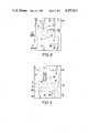
- FIGS. 2 and 3are schematic views of a compact physical construction of the embodiment of FIG. 1.
- FIG. 1shows a regeneration installation connected to an etching chamber 1 equipped with a rinsing chamber 2.
- the etching solution to be regeneratedwhich contains ammonium sulfate combined with copper tetrammin complex as an etchant, flows out of the etching chamber 1, through an inlet pipe 3 into a collecting container 4 that is connected to the etching chamber through a system of communicating pipes.
- the etching solutionflows in the inlet pipe 3 into a connecting pipe by gravity out of the etching chamber 1 and into the collecting container 4.
- the etching solution to be regeneratedis led by means of a pump 5 through a pressure line 6 to a pipe coupling 7, going out from which an etchant line 8 leads on to an electrolysis cell 9.
- a throughput controller 10 inserted in the etchant line 8determines the portion of the etching solution flowing to the electrolysis cell 9.
- Another connecting line 11is connected to the pipe coupling 7 which leads to a liquid jet pump 12, by means of which oxygen is introduced for reoxidation of the etching solution flowing back in the return line 13 to the etching chamber.
- a gas line 15is connected, the other end of which opens into the gas chamber above the electrolyte in the electrolysis cell 9 and is there supplied with oxygen which is produced at the anode 16 of the electrolysis cell 9, upon deposition of metal at the cathode 17.
- the etching solution propelled through the pressure line 6 by the pump 5 and then into the connecting line 11serves as the working medium of the liquid jet pump 12.
- An ammonia line 18connects into the gas line 15 for supply of ammonia from a supply tank 20 for ammonia equipped with an outlet valve control 19. Fresh ammonia can thus be introduced into the etching solution in order to control the pH value of the etching solution, the ammonia being drawn into the etching solution by the liquid jet pump 12 along with the gas containing oxygen sucked out of the electrolysis cell.
- a pH value measuring device 21 equipped with a measuring electrodesuitably is inserted in the etchant line 8 and the valve control 19 for the ammonia is connected to the pH meter 21 for pH regulation. If the pH value falls below a prescribed permissible limit value, the valve 19 opens and ammonia is introduced into the etching solution.
- the pH meterswitches the valve 19 on and off by means of electrical control components not shown in the drawing.
- a pressure relief line 22opens into the connecting line 11 upstream of the liquid jet pump 12 and serves to drain etching solution into the collecting container 4.
- the metal ion concentration in the etching solutiondetermines the manner of operation of the electrolysis cell.
- the apparatus 23accordingly is operatively connected to a magnetically controlled three-port valve 24 inserted at one end of the etchant line 8. Connected to the valve 24 are, on the one hand, the end piece 8' of the etchant line 8 leading to the electrolysis cell 9 and, on the other hand, a bypass line 25 that leads into the collecting container 4.
- the three-port valve 24is normally open towards the electrolysis cell 9. If the metal ion concentration of the etching solution falls below a predetermined value, the three-port valve 24 is switched over. The etching solution then flows through the bypass line 25. The electrolysis cell is switched off.
- An electrolyte overflow 26leads away from the output of the electrolysis cell and delivers etching solution of reduced metal ion content through a withdrawal line 27 to the collecting container 4.
- This etching solution of reduced metal contentis mixed in the collecting container with the etching solution to be regenerated and thereby reduces the metal ion concentration of the latter.
- the etching solution to be regeneratedis sucked out of the collecting container 4 by the pump 5 and is fed into the etchant line 8, through the throughput meter 10 and the pH value meter 21 to the apparatus 23 which reacts to the reduced metal ion concentration in the etching solution when that goes below a predetermined value.
- a drain container 28is also located underneath the electrolysis cell 9. It serves for emptying the electrolysis cell and is connected to the bottom of the electrolysis cell 9 by a drain pipe 29 that is normally shut off by a magnetic valve 30. Etching solution can also flow into the drain container 28 out of the electrolysis cell 9 through a second overflow 31.
- An electrolyte pump 32has the function of providing circulation of etching solution in the electrolysis cell 9.
- the electrolyte pumphas its suction line 33 dipping into the drain container 28, into which the etching solution flows through the overflow 31 and feeds the etching solution through a filter 34 in its pressure line 35 back to the electrolysis cell.
- the etching solutionenters into the electrolysis cell between the anode 16 and the cathode 17. After the electrolysis cell is shut off, the etching solution is emptied into the drain container 28 by opening of the magnetic valve 30. Before renewed operation of the electrolysis cell, the etching solution is fed back into the electrolysis cell out of a drain container by means of the electrolyte pump 32.
- etching solution containing ammonium sulfate and copper tetrammin complexwas used for etching of copper in the apparatus of the described embodiment.
- 150 liters of etching solutionwas put in circulation between the etching chamber and the regeneration installation.
- the fresh etching solutioncontained 150 g of ammonium sulfate and 50 g of copper per liter.
- etching solution at a temperature of 50° C. adjusted to a pH value of 9was sprayed onto workpieces to be etched by means of nozzles. Copper laminated circuit boards were etched.
- the etching velocityin this case measured 30 ⁇ m of copper surface removal per minute.
- the electrolysis cell installed in the regeneration systemhad a deposition power of 600 g of copper per hour.
- the electrolysis celloperated at 860 A of direct current, which corresponds to a current density of 10 A/dm 2 for an electrode surface of 860 cm 2 .
- the etching solution metal contentwas reduced in its passage through the electrolysis cell by 20 g of copper per liter.
- the etching solutionwas set at a pH value of 9 as a desired value, by addition of ammonia.
- the throughput controlleroperated at a desired value of 30 liters of etching solution per hour with a regulation deviation of ⁇ 2 1/h.
- a copper concentration of 53 g Cu/lwas measured in the etching solution, etching solution was directed to the electrolysis cell by a corresponding position of the three-port valve, until the copper concentration had dropped to 50 g Cu/l.
- the three-port valve 24was switched over and the electrolysis cell was shut down.
- the etching solution reduced in metal ion content in the electrolysis cellwas led back into the collecting container. Short dead periods resulted for the regulation loop.
- the parts of the regeneration installation schematically shown in FIG. 1are brought together, in physical construction of the illustrated embodiment, within a single housing that provides the collecting container 4, electrolysis cell 9 and the propelling means for the etching solution and the introduction of oxygen.
- These propelling meansinclude the pump 5 for leading the etching solution to be regenerated, the liquid jet pump 12 for introducing the gas-containing oxygen and ammonia into the etching solution, as well as the electrolyte pump 32 for the circlation of the etching solution in its composition as electrolyte in the electrolysis cell 9, as shown in FIGS. 2 and 3.
- the housing 40contains also the throughput meter 10, the pH meter 21 and the metal ion concentration measuring device 23. Beneath the electrolysis cell there is located--in the housing, arranged alongside the collecting container 4--the drain container 28 for the electrolyte.
- the parts of the regeneration installationare disposed in a space-saving manner within the housing. All that needs to be done to put the unit into use is to connect it to an etching chamber through the inlet pipe 3 and the return pipes 13 of the regeneration unit. The local distance between etching chamber and regeneration unit in the particular case makes no difference whatever affecting the proper and effective operation of the regeneration unit.
- the pipe coupling 7can be replaced by a filter to keep the particles out of the electrolysis cell, as shown in copending patent application Ser. No. 598,087, filed April 9, 1984, owned by the Assignee of the present application.
Landscapes
- Chemical & Material Sciences (AREA)
- Chemical Kinetics & Catalysis (AREA)
- General Chemical & Material Sciences (AREA)
- Engineering & Computer Science (AREA)
- Materials Engineering (AREA)
- Mechanical Engineering (AREA)
- Metallurgy (AREA)
- Organic Chemistry (AREA)
- ing And Chemical Polishing (AREA)
- Manufacturing Of Printed Circuit Boards (AREA)
Abstract
Description
Claims (6)
Applications Claiming Priority (2)
| Application Number | Priority Date | Filing Date | Title |
|---|---|---|---|
| DE19833340342DE3340342A1 (en) | 1983-11-08 | 1983-11-08 | METHOD AND PLANT FOR REGENERATING AN AMMONIA ACID SOLUTION |
| DE3340342 | 1983-11-08 |
Publications (1)
| Publication Number | Publication Date |
|---|---|
| US4557811Atrue US4557811A (en) | 1985-12-10 |
Family
ID=6213744
Family Applications (1)
| Application Number | Title | Priority Date | Filing Date |
|---|---|---|---|
| US06/669,312Expired - LifetimeUS4557811A (en) | 1983-11-08 | 1984-11-07 | Regeneration of an ammoniacal etching solution with recycling of solution with electrolytically reduced metal content to the regeneration input |
Country Status (4)
| Country | Link |
|---|---|
| US (1) | US4557811A (en) |
| EP (1) | EP0144742B1 (en) |
| JP (1) | JPS60116789A (en) |
| DE (2) | DE3340342A1 (en) |
Cited By (6)
| Publication number | Priority date | Publication date | Assignee | Title |
|---|---|---|---|---|
| US4784785A (en)* | 1987-12-29 | 1988-11-15 | Macdermid, Incorporated | Copper etchant compositions |
| US5391266A (en)* | 1990-05-05 | 1995-02-21 | Hoechst Aktiengesellschaft | Method of regulating the throughput in the electrochemical regeneration of chromosulfuric acid |
| US5417818A (en)* | 1993-11-24 | 1995-05-23 | Elo-Chem Atztechnik Gmbh | Process for the accelerated etching and refining of metals in ammoniacal etching systems |
| US6322675B1 (en)* | 2000-02-14 | 2001-11-27 | Carrier Corporation | Copper removal system for absorption cooling unit |
| US20050145580A1 (en)* | 2001-10-02 | 2005-07-07 | Rotometrics | Method and apparatus to clean particulate matter from a toxic fluid |
| WO2024149323A1 (en)* | 2023-01-13 | 2024-07-18 | 叶涛 | Method and device for electrolysis-assisted oxidative regeneration of alkaline copper chloride ammonia etching working solution |
Families Citing this family (6)
| Publication number | Priority date | Publication date | Assignee | Title |
|---|---|---|---|---|
| DE3429902A1 (en)* | 1984-08-14 | 1986-02-27 | Hans Höllmüller Maschinenbau GmbH & Co, 7033 Herrenberg | METHOD FOR ETCHING COPPER FILMS ON BOARDS UNDER ELECTROLYTIC RECOVERY OF COPPER FROM THE ACET SOLUTION |
| DE3839651A1 (en)* | 1988-11-24 | 1990-05-31 | Hoellmueller Hans | SYSTEM FOR ESTABLISHING OBJECTS |
| CA2029444A1 (en)* | 1990-03-21 | 1991-09-22 | Raymond A. Letize | System and process for etching with and regenerating, alkaline ammoniacal etchant solution |
| US5085730A (en)* | 1990-11-16 | 1992-02-04 | Macdermid, Incorporated | Process for regenerating ammoniacal chloride etchants |
| US5248398A (en)* | 1990-11-16 | 1993-09-28 | Macdermid, Incorporated | Process for direct electrolytic regeneration of chloride-based ammoniacal copper etchant bath |
| KR100964543B1 (en)* | 2008-10-31 | 2010-06-21 | 주식회사 하이소닉 | Cover for small camera module and its manufacturing method and small camera module equipped with the same |
Citations (4)
| Publication number | Priority date | Publication date | Assignee | Title |
|---|---|---|---|---|
| US2964453A (en)* | 1957-10-28 | 1960-12-13 | Bell Telephone Labor Inc | Etching bath for copper and regeneration thereof |
| US3772105A (en)* | 1970-07-24 | 1973-11-13 | Shipley Co | Continuous etching process |
| US3783113A (en)* | 1971-10-12 | 1974-01-01 | Shipley Co | Electrolytic regeneration of spent etchant |
| US4055751A (en)* | 1975-05-13 | 1977-10-25 | Siemens Aktiengesellschaft | Process control system for the automatic analysis and regeneration of galvanic baths |
Family Cites Families (5)
| Publication number | Priority date | Publication date | Assignee | Title |
|---|---|---|---|---|
| US3705061A (en)* | 1971-03-19 | 1972-12-05 | Southern California Chem Co In | Continuous redox process for dissolving copper |
| DE2216269A1 (en)* | 1972-04-05 | 1973-10-18 | Hoellmueller Maschbau H | METHOD OF ETCHING COPPER AND COPPER ALLOYS |
| JPS5617429A (en)* | 1979-07-23 | 1981-02-19 | Noriyuki Yoshida | Inputting method for character and symbol to computer system with video interface |
| DE3031567A1 (en)* | 1980-08-21 | 1982-04-29 | Elochem Ätztechnik GmbH, 7758 Meersburg | METHOD FOR REGENERATING AN AMMONIA ACAL SOLUTION |
| CS218296B1 (en)* | 1980-10-30 | 1983-02-25 | Antonin Stehlik | Method of continuous regeneration of the iron trichloride solution |
- 1983
- 1983-11-08DEDE19833340342patent/DE3340342A1/ennot_activeWithdrawn
- 1984
- 1984-11-02EPEP84113228Apatent/EP0144742B1/ennot_activeExpired
- 1984-11-02DEDE8484113228Tpatent/DE3464768D1/ennot_activeExpired
- 1984-11-07USUS06/669,312patent/US4557811A/ennot_activeExpired - Lifetime
- 1984-11-08JPJP59234239Apatent/JPS60116789A/enactiveGranted
Patent Citations (4)
| Publication number | Priority date | Publication date | Assignee | Title |
|---|---|---|---|---|
| US2964453A (en)* | 1957-10-28 | 1960-12-13 | Bell Telephone Labor Inc | Etching bath for copper and regeneration thereof |
| US3772105A (en)* | 1970-07-24 | 1973-11-13 | Shipley Co | Continuous etching process |
| US3783113A (en)* | 1971-10-12 | 1974-01-01 | Shipley Co | Electrolytic regeneration of spent etchant |
| US4055751A (en)* | 1975-05-13 | 1977-10-25 | Siemens Aktiengesellschaft | Process control system for the automatic analysis and regeneration of galvanic baths |
Non-Patent Citations (2)
| Title |
|---|
| "Appl. of Specific Ion Electrodes to Electroplating Analysis" by M. S. Fr, Plating, vol. 58 #7, Jul. 1971, pp. 686-693. |
| Appl. of Specific Ion Electrodes to Electroplating Analysis by M. S. Frant, Plating, vol. 58 7, Jul. 1971, pp. 686 693.* |
Cited By (7)
| Publication number | Priority date | Publication date | Assignee | Title |
|---|---|---|---|---|
| US4784785A (en)* | 1987-12-29 | 1988-11-15 | Macdermid, Incorporated | Copper etchant compositions |
| US5391266A (en)* | 1990-05-05 | 1995-02-21 | Hoechst Aktiengesellschaft | Method of regulating the throughput in the electrochemical regeneration of chromosulfuric acid |
| US5417818A (en)* | 1993-11-24 | 1995-05-23 | Elo-Chem Atztechnik Gmbh | Process for the accelerated etching and refining of metals in ammoniacal etching systems |
| US6322675B1 (en)* | 2000-02-14 | 2001-11-27 | Carrier Corporation | Copper removal system for absorption cooling unit |
| US20050145580A1 (en)* | 2001-10-02 | 2005-07-07 | Rotometrics | Method and apparatus to clean particulate matter from a toxic fluid |
| US7404904B2 (en)* | 2001-10-02 | 2008-07-29 | Melvin Stanley | Method and apparatus to clean particulate matter from a toxic fluid |
| WO2024149323A1 (en)* | 2023-01-13 | 2024-07-18 | 叶涛 | Method and device for electrolysis-assisted oxidative regeneration of alkaline copper chloride ammonia etching working solution |
Also Published As
| Publication number | Publication date |
|---|---|
| EP0144742A1 (en) | 1985-06-19 |
| DE3340342A1 (en) | 1985-05-15 |
| EP0144742B1 (en) | 1987-07-15 |
| DE3464768D1 (en) | 1987-08-20 |
| JPS60116789A (en) | 1985-06-24 |
| JPH0536509B2 (en) | 1993-05-31 |
Similar Documents
| Publication | Publication Date | Title |
|---|---|---|
| US4557811A (en) | Regeneration of an ammoniacal etching solution with recycling of solution with electrolytically reduced metal content to the regeneration input | |
| US4017343A (en) | Method of and apparatus for etching | |
| US4576677A (en) | Method and apparatus for regenerating an ammoniacal etching solution | |
| US3095121A (en) | Chemical feed control system | |
| US5690804A (en) | Method and plant for regenerating sulfate electrolyte in steel strip galvanizing processes | |
| WO2019007407A1 (en) | Ammonia-stilling recycling process for alkaline waste etching solution of printed circuit board, and system thereof | |
| CN106757294B (en) | A method of for supplementing copper sulphate in copper plating groove | |
| GB2067595A (en) | Method and apparatus for replenishing an electroplating bath with metal to be deposited | |
| EP0088852A1 (en) | A process for regenerating electroless plating bath and a regenerating apparatus of electroless plating bath | |
| US4772365A (en) | Method for etching materials | |
| CN120019176A (en) | A method and device for optimizing insoluble anode copper plating process combined with electrolytic copper dissolution | |
| US4719128A (en) | Method of and apparatus for bailout elimination and for enhancing plating bath stability in electrosynthesis/electrodialysis electroless copper purification process | |
| US4761213A (en) | Treatment facility particularly for printed circuit boards to be treated while in a horizontal plane | |
| CN218403896U (en) | Discharge wastewater recycling treatment device and waste lithium battery treatment system | |
| CN217780923U (en) | Improve helping of ammonia process desulfurization slurry liquid performance and strain device | |
| JPH0429745B2 (en) | ||
| US5076885A (en) | Process for etching workpieces | |
| US5032204A (en) | Installation for etching objects | |
| CN208762342U (en) | A kind of water-saving silver powder cleaning device | |
| US2223832A (en) | Process for the recovery of precious metals present in sea water | |
| JP3928187B2 (en) | Method and apparatus for dephosphorization in wastewater | |
| CN222182529U (en) | A fully automatic intelligent control system for trivalent iron dissolving copper circulation | |
| JPS589150B2 (en) | Electroless copper plating equipment | |
| JPS5826427B2 (en) | Electroless copper plating method | |
| JP2001107271A (en) | Copper chloride etchant electrolytic regeneration system |
Legal Events
| Date | Code | Title | Description |
|---|---|---|---|
| AS | Assignment | Owner name:KERNFORSCHUNGSANLAGE JULICH GESELLSCHAFT MIT BSCHR Free format text:ASSIGNMENT OF ASSIGNORS INTEREST.;ASSIGNORS:FURST, LEANDER;HOLZER, WALTER;REEL/FRAME:004335/0828;SIGNING DATES FROM 19841023 TO 19841025 Owner name:ELO-CHEM ATZTECHNIK GMBH DROSTEWEG 21, D-7758 MEER Free format text:ASSIGNMENT OF ASSIGNORS INTEREST.;ASSIGNORS:FURST, LEANDER;HOLZER, WALTER;REEL/FRAME:004335/0828;SIGNING DATES FROM 19841023 TO 19841025 Owner name:KERNFORSCHUNGSANLAGE JULICH GESELLSCHAFT MIT BSCHR Free format text:ASSIGNMENT OF ASSIGNORS INTEREST;ASSIGNORS:FURST, LEANDER;HOLZER, WALTER;SIGNING DATES FROM 19841023 TO 19841025;REEL/FRAME:004335/0828 Owner name:ELO-CHEM ATZTECHNIK GMBH,GERMANY Free format text:ASSIGNMENT OF ASSIGNORS INTEREST;ASSIGNORS:FURST, LEANDER;HOLZER, WALTER;SIGNING DATES FROM 19841023 TO 19841025;REEL/FRAME:004335/0828 | |
| STCF | Information on status: patent grant | Free format text:PATENTED CASE | |
| FEPP | Fee payment procedure | Free format text:PAYOR NUMBER ASSIGNED (ORIGINAL EVENT CODE: ASPN); ENTITY STATUS OF PATENT OWNER: LARGE ENTITY | |
| FPAY | Fee payment | Year of fee payment:4 | |
| AS | Assignment | Owner name:FORSCHUNGSZENTRUM JULICH GMBH Free format text:CHANGE OF NAME;ASSIGNOR:KERNFORSCHUNGSANLAGE JULICH GMBH;REEL/FRAME:005589/0899 Effective date:19900102 | |
| FPAY | Fee payment | Year of fee payment:8 | |
| FPAY | Fee payment | Year of fee payment:12 |