US4557282A - Coin-sorting wheel and counter for high-speed coin-sorting and counting apparatus - Google Patents
Coin-sorting wheel and counter for high-speed coin-sorting and counting apparatusDownload PDFInfo
- Publication number
- US4557282A US4557282AUS06/526,421US52642183AUS4557282AUS 4557282 AUS4557282 AUS 4557282AUS 52642183 AUS52642183 AUS 52642183AUS 4557282 AUS4557282 AUS 4557282A
- Authority
- US
- United States
- Prior art keywords
- coin
- engaging
- wheel
- shaft
- support member
- Prior art date
- Legal status (The legal status is an assumption and is not a legal conclusion. Google has not performed a legal analysis and makes no representation as to the accuracy of the status listed.)
- Expired - Fee Related
Links
- 230000002441reversible effectEffects0.000claimsabstract4
- 230000002093peripheral effectEffects0.000claimsdescription26
- 238000003825pressingMethods0.000claimsdescription2
- 239000002356single layerSubstances0.000claimsdescription2
- 125000006850spacer groupChemical group0.000abstractdescription5
- 230000000712assemblyEffects0.000description9
- 238000000429assemblyMethods0.000description9
- 230000000994depressogenic effectEffects0.000description3
- 238000000034methodMethods0.000description3
- 230000008569processEffects0.000description3
- PXHVJJICTQNCMI-UHFFFAOYSA-NNickelChemical compound[Ni]PXHVJJICTQNCMI-UHFFFAOYSA-N0.000description2
- 238000010276constructionMethods0.000description2
- 238000003780insertionMethods0.000description2
- 230000037431insertionEffects0.000description2
- 238000004519manufacturing processMethods0.000description2
- 230000009471actionEffects0.000description1
- 230000009286beneficial effectEffects0.000description1
- 230000000903blocking effectEffects0.000description1
- 238000004140cleaningMethods0.000description1
- 239000007799corkSubstances0.000description1
- 230000001934delayEffects0.000description1
- 230000000881depressing effectEffects0.000description1
- 238000007689inspectionMethods0.000description1
- 238000009434installationMethods0.000description1
- 230000003993interactionEffects0.000description1
- 208000037805labourDiseases0.000description1
- 239000002184metalSubstances0.000description1
- 229910052751metalInorganic materials0.000description1
- 238000012986modificationMethods0.000description1
- 230000004048modificationEffects0.000description1
- 229910052759nickelInorganic materials0.000description1
- 230000002035prolonged effectEffects0.000description1
Images


Classifications
- G—PHYSICS
- G07—CHECKING-DEVICES
- G07D—HANDLING OF COINS OR VALUABLE PAPERS, e.g. TESTING, SORTING BY DENOMINATIONS, COUNTING, DISPENSING, CHANGING OR DEPOSITING
- G07D3/00—Sorting a mixed bulk of coins into denominations
- G07D3/16—Sorting a mixed bulk of coins into denominations in combination with coin-counting
- G—PHYSICS
- G07—CHECKING-DEVICES
- G07D—HANDLING OF COINS OR VALUABLE PAPERS, e.g. TESTING, SORTING BY DENOMINATIONS, COUNTING, DISPENSING, CHANGING OR DEPOSITING
- G07D3/00—Sorting a mixed bulk of coins into denominations
- G07D3/12—Sorting coins by means of stepped deflectors
- G07D3/128—Rotary devices
Definitions
- This inventionrelates to coin-sorting and counting apparatus, and more particularly, to coin-sorting wheels and counter arrangement for sorting and counting coins carried on a rotating disc.
- the centrifugal forceis imparted to the coins by the rotation of a disc onto which coins are delivered in bulk, usually through a central hopper.
- the coinsare then guided by a coin-queueing head to deliver them in a queue to a position adjacent a peripheral retaining rim of the disc.
- the coinsare selectively engaged according to denomination by one of a plurality of coin-engagement means such as wheels, blades, cams or the like positioned around the peripheral rim.
- the coin-engagement meansdepresses or lifts the coins to free them from the peripheral rim of the disc and allow the centrifugal force to hurl them through the air a distance to one of a plurality of corresponding catching devices.
- the coinsare then diverted to appropriate collecting bags.
- the sortingis typically accomplished by the coin-engagement means based upon the differences in diameter of the various denominations of coins being processed.
- Conventional coin-engagement meansrequire the coins to be in a single-layer, single-file row at the peripheral rim to avoid malfunctioning of the machine and to insure a proper count.
- the countis usually made by photoelectric means which sense the number of coins entering each catching device as the coins reach the catching device.
- the photoelectric meanscounts the coins by measuring the number of times a produced beam of light extending across the flight path of the coins is broken.
- a coin-engagement meanswhich has proven particularly successful is a wheel rotatably mounted on a fixed shaft.
- the wheelis positioned above the path of travel of the queue, and the rim of the wheel engages each coin individially and depresses the radially inner edge of the coin into a flexible pad covering the disc. This action raises the radially outward edge of the coin above the peripheral rim and the centrifugal force hurls the coin over the rim to one of the catching devices.
- the wheelsare mounted at spaced intervals along the path of travel of the queue and positioned at preselected distances radially inward of the peripheral rim of the disc at which the queue is formed.
- the largest diameter coinsare sorted first by a wheel positioned a distance away from the peripheral rim which causes the wheel to engage the upper surface of the coin adjacent to its radially inward edge. Spaced therefrom is another wheel correspondingly positioned inward of the rim along the queue path by a lesser distance to engage the next smaller diameter coins.
- additional wheelsare positioned to engage coins of each successively smaller diameter. Smaller diameter coins pass unaffected by any wheel positioned for engagement of a larger diameter coin since they are at a distance from the peripheral rim more than the diameter of the smaller coin.
- the wheelsare positioned at preselected distances above the flexible pad. The distance depends on the thickness of the coin to be engaged by a particular wheel, since the coin need only be pressed into the flexible pad by an amount sufficient to raise the radially outward edge of the coin above the peripheral rim. Insufficient depressing of a coin results in it not being hurled from the disc, and over pressing places unnecessary drag on the rotating disc and increases wheel wear.
- the wheelsshould be adjustable radially and vertically over a wide range of positions, which has not been possible in the past. It would be beneficial if a single design wheel assembly could be used for all requirements. In any event, for optimum operation of the machine, particularly when operating at high speeds, the wheels must be finely set or tuned for the particular coin-queueing head being used on the machine, and the wheels must be re-tuned periodically to compensate for head and wheel wear, and changes in the alignment of the head on the disc. In the past, such fine adjustments have been difficult and time consuming to make. Furthermore, in the past, when the wheels wore significantly, the wheel had to be discarded and replaced with a new wheel. This required consuming disassembly of the machine, and installation and tuning of the new wheel.
- Another problem encountered with such machinesinvolves obtaining correct counts of the coins processed by the machine. Because the disc labors under varying loads and partial blocking conditions during its normal operation, the speed of rotation of the disc temporarily slow down and speed up accordingly. These fluctuations in rotational speed occur frequently during operation of the machine and cause the disc to hurl successive coins from the disc at different linear speeds. This is because the centrifugal force imparted to the coins varies depending on the rotational speed of the disc. As a result, the travel of one coin of a particular denomination from the coin-engagement means over the distance to the catching device, whereat the coin is counted, may occur at a different speed and take longer than the travel of the next coin of that denomination sorted. Consequently, the subsequent coin may hit, catch up with or even overtake the first coin.
- the pair of coinsmay be counted only once, producing an erroneous count.
- the present inventionresides in a coin-engaging apparatus for use with a coin-sorting machine having a rotatable flexible surface, comprising: a support member mountable within a generally horizontally oriented receiver of the machine, the support member being rotatably and horizontally positionable within the receiver, the support member rotatably supporting a coin-engaging wheel for rotation about an axis eccentric with the support member, the coin-engaging wheel being positionable above the surface for engaging coins carried thereon; and means for lockably retaining the position of the support member within the receiver during operation of the machine.
- the support memberhas a longitudinal, selectively extendable member projectable from an end of the support member mountable within the receiver for engaging an internal end wall of the receiver for adjustably setting the limit of horizontally inward movement of the support member in the receiver.
- the extendable memberis threaded to threadably engage threads of the support member.
- the support memberalso has a first shaft positionable within the receiver with an eccentric second shaft extending from one end of the first shaft for rotatably supporting the coin-engaging wheel.
- the second shaftis detachable from the first shaft for removal of the coin-engaging wheel.
- the second shaftis a threaded shoulder screw having a circumferential bearing surface for rotatably supporting the coin-engaging wheel.
- the coin-engaging wheelhas at least one substantially flat sidewall extending to a coin-contacting circumferential sidewall, with the sidewall being positionable toward the coin being engaged. To prolong the operating life of the coin-engaging wheel, the wheel has two oppositely disposed substantially flat sidewalls to allow a reversing of the wheel.
- the coin-engaging wheelalso includes a hub rotatably supportable by the first member, and the two oppositely disposed sidewalls are symmetrically positioned along the hub. The two oppositely disposed sidewalls terminal radially outward of the axis of rotation of the coin-engaging wheel to define a coin-contacting edgewall therebetween, the edgewall having substantially square edges.
- a coin counting meansis positioned adjacent to each of the coin-engaging means for counting coins as they are sorted by the coin-engaging means.
- a cylindrical shaftis positionable within a generally horizontally oriented cylindrical opening of the machine sized to receive the shaft therein.
- the openinghas an open and a closed end, and the shaft is rotatably and horizontally positionable within the opening.
- the shafthas an eccentric, longitudinal threaded first bore at an end positionable toward the open end of the opening, and has a longitudinal threaded second bore at another end positionable toward the closed end of said opening.
- the coin-engaging wheelis rotatably mounted along its axis of rotation on a threaded first member, the first member being threadedly engageable by the eccentric first bore for positioning the wheel above the surface.
- a threaded second memberis threadedly engageable by the threaded second bore and adjustably extendable from the second bore for engaging the closed end of the opening.
- meansare provided for locking the shaft in a selected rotational position within the opening, whereby adjustment of the second member adjusts the horizontal position of the wheel relative to the surface and adjustment of the rotational position of the shaft within the opening adjusts the vertical position of the wheel relative to the surface.
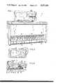
- FIG. 1is an isometric frontal view of a coin-sorting and counting apparatus embodying the improved coin-sorting wheel and counter arrangement of the present invention
- FIG. 2is an enlarged, fragmentary top plan view of the coin loading tray of the apparatus shown in FIG. 1;
- FIG. 3is a top plan view of the coin-sorting wheels and counter arrangement of the present invention shown positioned around a coin-queueing head and above a rotatable disc with a coin shown in phantom line positioned under each coin-sorting wheel;
- FIG. 4is an enlarged, sectional view taken substantially along the line 4--4 of FIG. 3;
- FIG. 5is an enlarged, fragmentary, sectional view taken substantially along the line 5--5 of FIG. 3, showing a coin being engaged by a coin-sorting wheel;
- FIG. 6is an enlarged isometric, exploded view of a coin-sorting wheel assembly of the present invention.
- the present inventionis embodied in a high-speed coin-sorting and counting apparatus, indicated by reference numeral 10. More specifically, the present invention is embodied in an improved coin-sorting wheel assembly 12 and counter arrangement for such an apparatus.
- an undifferentiated mix of coins with random orientationis poured into a loading tray 14 of the apparatus 10 and moves therefrom into a hopper 16 located beneath the tray and immediately above a queueing head 18.
- the apparatuswhen designed to handle U.S. coinage, the apparatus processes simultaneously pennies, nickels, dimes, quarters, half-dollars, and Susan B. Anthony dollar denomination coins.
- the apparatus 10includes a stationary support base 24 which has three upright supports 26, 28 and 30 attached thereto and which supports a rotatable, circular disc 32.
- the queueing head 18is attached by a hinge 34 to two of the upright supports 26 and 28 and by a flange 36 to the upright support 30 for holding the head in position above an upper surface 38 of the disc 32 by approximately the thickness of the thickest coin to be processed by the apparatus 10.
- the precise vertical position of the head 18 above the upper surface 38is adjustable through adjustment bolts 40, 42 and 44, which hold the hinge 34 and the flange 36 to the upright supports 26, 28 and 30.
- the hinge 34permits easy lifting of the head 18 away from the disc 32 for inspection cleaning and clearing of any jams or obstructions which may occur.
- the bolt 44includes a thumb-operated cap 46 which may be readily unscrewed to permit the head 18 to be moved about the hinge 34.
- a motor 48drives the disc 32 through a belt 50 to rotate it in a clockwise direction indicated by arrow 52 when viewed from above.
- the belt 50rides on a pulley 54 formed as an integral part of the disc 32. The rotation of the disc 32 imparts a centrifugal force to the coins being processed.
- the hopper 16is rigidly attached to and supported above the queueing head 18, and has a cork screw interior shape.
- the coins moved into the hopper 16are funneled into a central circular opening 56 in the head.
- a lower surface or face 58 of the head 18faces toward the upper surface 38 of the rotating disc 32 and is tapered upwardly from the central opening 56 to its outer perimeter at an angle of approximately four degrees.
- the taper of the lower surface 58 of the head 18conforms with the taper on the upper surface 38 of the disc 32.
- the taperis provided to facilitate holding coins down on the upper surface 38 of the disc 32, particularly when they reach a peripheral rim 60 of the disc.
- a resilient frictional pad 62covers the disc 32 and defines the upper surface 38 of the disc.
- the lower surface 58 of the head 18is a low-friction surface, preferably made of a durable metal.
- a conical member 64is fixedly attached to the disc 32, at its center, below the central opening 56, to prevent coins from remaining in the center of the disc by their avoiding the centrifugal force caused by rotation of the disc. The centrifugal force is necessary to move the coins from the central opening 56 to the peripheral rim 60.
- the disc 32is rotatably mounted to the base 24 by a shaft 66 supported by a pair of frictionless roller bearings 68.
- the coinsleave the head 18 through the exit passage 72 under the influence of the rotating disc 32, whereupon they are free of any control by the head.
- the disc 32then carries the coins in the queue which is positioned adjacent to the peripheral rim 60 of the disc to a number of the coin-sorting wheel assemblies 12 for sorting by denomination.
- the coin-sorting wheel assemblies 12are mounted to the head 18 and spaced along the outer perimeter of the head.
- the coin-sorting wheels 74 of the coin-sorting wheel assemblies 12extend from the head radially by varying distances corresponding to the diameter of the coin to be depressed, with the largest diameter coin being sorted first, then the next largest, and so on.
- the apparatus 10includes six coin-sorting wheel assemblies 12 and will process and sort six denominations of coins in the same batch, i.e., penny, nickel, dime, quarter, half-dollar, and Susan B. Anthony dollar coins.
- the coin-sorting wheel 74depresses the inner edge of a coin into the resilient pad 62 causing the outer edge to raise and be hurled over the peripheral rim 60 of the disc 32 by the centrifugal force into a coin catching device 76.
- the coinsare counted by an electro-optical sensor or photoelectric cell 78 as the coins are travelling through the air.
- One catching device 76is positioned across from each sorting wheel 74.
- a last wheel 80(see FIG. 3) is provided with a rim width size sufficient to engage all diameter coins being processed and cause the coin to be sufficiently pressed into the resilient pad 62 and bounced upwardly therefrom by the resiliency of the pad that the centrifugal force will hurl it off the disc 32 into a chute 82 which diverts the coin into a special holding compartment (not shown).
- the coin-sorting wheel assembly 12includes one of the coin-sorting wheels 74 rotatably attached along its central rotational axis by a shoulder screw 84 to an elongated cylindrical shaft 86.
- the coin-sorting assembly 12is mounted to the head 18 by insertion of the shaft 86 into a radially oriented end-capped cylindrical bore 88 with an inward blocked end 89 provided in the head along its outer perimeter.
- the end-capped bore 88has a diameter sized to receive the shaft 86 therein and a depth sufficient to permit full insertion of the shaft to place the coin-sorting wheel 74 in proper radial alignment above the largest diameter coin to be processed by the apparatus 10.
- a lock screw 90locks the shaft 86 in place within the end-capped bore 88.
- the shaft 86has an eccentric, interiorly threaded longitudinal hole 92 extending fully therethrough which is sized to threadedly receive the shoulder screw 84 in an outwardly facing end 94 of the through-hole and an adjustable spacer or set screw 96 in an inwardly facing end 98 of the through-hole. Adjustment of the distance the spacer screw 94 protrudes from the inwardly facing end 98 of the through-hole 92 determines the radial positioning of the coin-sorting wheel 74 when the shaft 86 is inserted into the end-capped bore 88 sufficiently to butt the spacer screw against the blocked end 89 of the bore.
- radial adjustment of the coin-sorting wheel 74may be accomplished merely by loosening the lock screw 90, removing the shaft 86 from the end-capped bore 88, turning the spacer screw 96 in or out by an amount corresponding to the desired radial adjustment of the coin-sorting wheel, and then replacing and locking the shaft in the end-capped bore.
- the shoulder screw 84has an elongated shaft 99 with a head 100 at one end.
- An opposite end portion 102 of the screw 84has exterior threads sized to threadably engage the interior threads of the through-hole 92.
- Extending between the head 100 and the threaded end portion 102 of the screw 84is a bearing surface 104 on which the coin-sorting wheel 74 rotates freely.
- the bearing surface 104has a larger diameter than the threaded end portion 102 to define a shoulder 106 which limits the inward travel of the screw into the through-hole 92.
- the threads of the through-hole 92 and the threaded end portion 102 of the screw 84are threaded in a direction which results in the tightening of the screw in the through-hole as a result of any frictional forces between the coin-sorting wheel 74 and the bearing surface 104 resulting from rotation of the wheel during operation of the apparatus 10.
- the bearing surface 104has a smaller diameter than the shaft 86, with the longitudinal travel of the coin-sorting wheel 74 on the bearing surface 104 being inwardly limited by the end wall of the shaft 86 and outwardly limited by the head 100.
- one standardized coin-sorting wheel assembly 12 having a standardized coin-sorting wheel 74can be used for sorting all denominations of coins and coinage of various countries, and it is not necessary to manufacture new wheel assemblies for each denomination or each country. This reduces design and manufacturing costs and delays, and inventory problems. Furthermore, the coin-sorting assemblies 12 of the present invention permit accurate, easy and rapid initial set up adjustments of the coin-sorting wheels 74 and subsequent fine tuning of the wheels. The simple construction also allows for easy replacement of worn coin-sorting assemblies 12 or wheels 74.
- the coin-sorting wheel 74itself has a novel design with a central elongated hub 110 defining the central rotational axis of the wheel, and a circular wheel disc 112 extending radially outward from the longitudinal center of the hub transverse to the rotational axis.
- the hub 110has a longitudinally extending interior bearing wall 114 sized to ride on the bearing surface 104 of the shoulder screw 84 to allow the wheel to freely rotate under the rotational force applied to the wheel as it engages a coin.
- the coin-sorting wheel 74has a peripheral rim or edge wall 116 which contacts the coin's upper surface when the wheel engages the coin to depress it into the resilient pad 62 for hurling from the rotating disc 32.
- Wear along the peripheral rim 116 of the wheel disc 112usually occurs only along its outer edge which is squared for best interaction with the coins.
- the wheel disc 112 of the present inventionis provided with symmetrical sides 118 to allow reversal of the coin-sorting wheel 74 on the shoulder screw 84 should the outer edge of the wheel disc become worn and rounded from use, to present a new square outer edge to the coins. In such fashion, the useful life of the wheel discs 112 is effectively doubled.
- the sensors 78 which count the coinsare located adjacent to their corresponding coin-sorting assembly 12 with their light beams across the flight path of the coins therefrom. Since the coin-sorting assembly 12 can only engage one coin at a time, no matter how fast or slow the rotating disc 32 may be turning at the moment the coin is engaged, the coins are counted individually even if one coin may subsequently collide, catch up with or overtake another during flight in the area of the coin catching device 76.
- the initial travel of a coin along its flight pathmust be very smooth and predictable. If the coin-sorting wheel or other means used to free the coin from the peripheral rim 60 of the rotating disc 32 causes the coin to wobble, flip over, or turn in flight just after it is depressed and before it is clear of the sensor 78, it may strike the sensor or avoid passing through its sensing light beam.
- the design of the coin-sorting wheel 74 of the present inventionhas proven to be particularly effective in this regard and to produce a smooth and predictable initial coin flight.
- the sides 118 of the wheel disc 112have a relatively flat profile, at least in the area adjacent to the rim 116 of the wheel disc, which is believed to account for the improved performance.
- the remainder of the flight pathis also smoother and more predictable, consequently helping to solve the problem of design and positioning of the coin-catching devices 76 to catch all coins which are hurled from the rotating disc 32 and reduce interference resulting from coins ricocheting within the coin-catching device once caught.
Landscapes
- Physics & Mathematics (AREA)
- General Physics & Mathematics (AREA)
- Testing Of Coins (AREA)
- Pinball Game Machines (AREA)
Abstract
Description
Claims (29)
Priority Applications (7)
| Application Number | Priority Date | Filing Date | Title |
|---|---|---|---|
| US06/526,421US4557282A (en) | 1983-08-25 | 1983-08-25 | Coin-sorting wheel and counter for high-speed coin-sorting and counting apparatus |
| ZA846497AZA846497B (en) | 1983-08-25 | 1984-08-21 | Coin-sorting wheel and counter for high-speed coin counting apparatus |
| AR84297709AAR245998A1 (en) | 1983-08-25 | 1984-08-24 | Coin-sorting wheel and counter for high-speed coin-sorting and counting apparatus |
| JP59176520AJPS60101689A (en) | 1983-08-25 | 1984-08-24 | Coin classifying wheel and counter for fast coin classifier/calculater |
| AU32351/84AAU565169B2 (en) | 1983-08-25 | 1984-08-24 | Coin sorting wheel and counter for high-speed coin counting apparatus |
| EP84110131AEP0137266A3 (en) | 1983-08-25 | 1984-08-24 | Coin-sorting wheel and counter for high-speed coin-sorting and counting apparatus |
| BR8404250ABR8404250A (en) | 1983-08-25 | 1984-08-24 | APPLIANCE WITH WHEEL AND COUNTER FOR HIGH SPEED COIN SELECTION AND COUNTING |
Applications Claiming Priority (1)
| Application Number | Priority Date | Filing Date | Title |
|---|---|---|---|
| US06/526,421US4557282A (en) | 1983-08-25 | 1983-08-25 | Coin-sorting wheel and counter for high-speed coin-sorting and counting apparatus |
Publications (1)
| Publication Number | Publication Date |
|---|---|
| US4557282Atrue US4557282A (en) | 1985-12-10 |
Family
ID=24097267
Family Applications (1)
| Application Number | Title | Priority Date | Filing Date |
|---|---|---|---|
| US06/526,421Expired - Fee RelatedUS4557282A (en) | 1983-08-25 | 1983-08-25 | Coin-sorting wheel and counter for high-speed coin-sorting and counting apparatus |
Country Status (7)
| Country | Link |
|---|---|
| US (1) | US4557282A (en) |
| EP (1) | EP0137266A3 (en) |
| JP (1) | JPS60101689A (en) |
| AR (1) | AR245998A1 (en) |
| AU (1) | AU565169B2 (en) |
| BR (1) | BR8404250A (en) |
| ZA (1) | ZA846497B (en) |
Cited By (26)
| Publication number | Priority date | Publication date | Assignee | Title |
|---|---|---|---|---|
| US4966570A (en)* | 1987-07-30 | 1990-10-30 | Ristvedt Victor G | Coin sorting apparatus for sorting coins of selected denominations |
| US5011455A (en)* | 1990-02-12 | 1991-04-30 | Cummins-Allison Corporation | Coin sorter with automatic bag-switching |
| US5098339A (en)* | 1991-01-23 | 1992-03-24 | 7's Unlimited, Inc. | Coin feeding device |
| US5104353A (en)* | 1987-07-30 | 1992-04-14 | Ristvdet-Johnson, Inc. | Coin sorting apparatus with rotating disc |
| US5123873A (en)* | 1990-02-12 | 1992-06-23 | Cummins-Allison Corp. | Coin sorter with automatic bag-switching |
| US5141472A (en)* | 1990-10-30 | 1992-08-25 | Cummins-Allison Corp. | Disc-type coin sorter with adjustable gaging device |
| US5145455A (en)* | 1991-05-15 | 1992-09-08 | Cummins-Allison Corp. | Wave-type coin sorter |
| US5163866A (en)* | 1991-04-29 | 1992-11-17 | Cummins-Allison Corp. | Disc-type coin sorter with multiple-path queuing |
| US5163867A (en)* | 1991-05-15 | 1992-11-17 | Cummins-Allison Corp. | Disc-type coin sorter with multiple-path queuing |
| US5167571A (en)* | 1991-04-11 | 1992-12-01 | International Game Technology | Coin handling machine |
| US5194037A (en)* | 1987-04-01 | 1993-03-16 | Cummins-Allison Corp. | Disc-type coin sorting mechanism for sorting coins by radial locations of the inner edges of the coins |
| US5205780A (en)* | 1991-04-29 | 1993-04-27 | Cummins-Allison Corporation | Disc-type coin sorter with eccentric feed |
| US5286226A (en)* | 1991-06-03 | 1994-02-15 | Cummins-Allison Corporation | Disc-type coin sorter |
| US5370575A (en)* | 1994-01-06 | 1994-12-06 | Cummins-Allison Corp. | Coin sorting mechanism |
| US5372542A (en)* | 1993-07-09 | 1994-12-13 | Cummins-Allison Corp. | Disc coin sorter with improved exit channel |
| WO1995004980A1 (en)* | 1993-08-10 | 1995-02-16 | Raha-Automaattiyhdistys | Dispenser for a coin-operated game-playing apparatus |
| US5401211A (en)* | 1993-08-05 | 1995-03-28 | Cummins-Allison Corp. | Disc coin sorter with positive guide wall between exit channels |
| US5425669A (en)* | 1994-01-07 | 1995-06-20 | Cummins-Allison Corp. | Coin queuing and sorting arrangement |
| US5474497A (en)* | 1993-09-28 | 1995-12-12 | Cummins-Allison Corp. | Method for terminating coin sorting using pressureless exit channels and immediate stopping |
| US5501631A (en)* | 1994-01-06 | 1996-03-26 | Cummins-Allison Corp. | Coin handling device with an improved lubrication system |
| US5584758A (en)* | 1993-08-05 | 1996-12-17 | Cummins-Allison Corp. | Disc-type coin sorter with adjustable targeting inserts |
| GB2355104A (en)* | 1999-08-06 | 2001-04-11 | Asahi Seiko Co Ltd | Coin hopper apparatus |
| US20040055902A1 (en)* | 2002-09-20 | 2004-03-25 | Peklo John C | Removable coin bin |
| US20050067305A1 (en)* | 2002-09-20 | 2005-03-31 | Bochonok Steve T. | Removable coin bin |
| EP1483749A4 (en)* | 2002-03-11 | 2007-11-14 | Cummins Allison Corp | Coin processing system |
| US20120088431A1 (en)* | 2010-10-04 | 2012-04-12 | Pedersen Bradley D | Child's Activity Toy |
Families Citing this family (4)
| Publication number | Priority date | Publication date | Assignee | Title |
|---|---|---|---|---|
| US5120655A (en)* | 1985-12-20 | 1992-06-09 | Zeagen, Inc. | Riboflavin producing strains of microorganisms |
| US5299977A (en)* | 1990-05-14 | 1994-04-05 | Cummins-Allison Corp. | Coin handling system |
| JP2639766B2 (en)* | 1991-04-10 | 1997-08-13 | ローレルバンクマシン株式会社 | Money sorting device |
| US5782686A (en)* | 1995-12-04 | 1998-07-21 | Cummins-Allison Corp. | Disc coin sorter with slotted exit channels |
Citations (9)
| Publication number | Priority date | Publication date | Assignee | Title |
|---|---|---|---|---|
| US2348936A (en)* | 1940-10-11 | 1944-05-16 | Brandt Automatic Cashier Co | Coin sorting and counting machine |
| US2906276A (en)* | 1956-03-08 | 1959-09-29 | Brandt Automatic Cashier Co | Coin sorter |
| US2977961A (en)* | 1957-12-06 | 1961-04-04 | Brandt Automatic Cashier Co | Coin sorting machine |
| US3795252A (en)* | 1972-11-20 | 1974-03-05 | Westermann W | Centrifugal coin sorter |
| US3998237A (en)* | 1975-04-25 | 1976-12-21 | Brandt, Inc. | Coin sorter |
| US4086928A (en)* | 1976-08-06 | 1978-05-02 | Ristvedt Victor G | Coin sorting machine |
| US4098280A (en)* | 1976-10-22 | 1978-07-04 | Ristvedt Victor G | Coin handling machine |
| US4111216A (en)* | 1976-04-01 | 1978-09-05 | Systems And Technics S.A. | Centrifugal coin sorter |
| US4234003A (en)* | 1978-06-30 | 1980-11-18 | Ristvedt Victor G | Coin handling machine |
Family Cites Families (1)
| Publication number | Priority date | Publication date | Assignee | Title |
|---|---|---|---|---|
| US3771538A (en)* | 1971-07-26 | 1973-11-13 | K Reis | Coin sorting and counting machines |
- 1983
- 1983-08-25USUS06/526,421patent/US4557282A/ennot_activeExpired - Fee Related
- 1984
- 1984-08-21ZAZA846497Apatent/ZA846497B/enunknown
- 1984-08-24JPJP59176520Apatent/JPS60101689A/enactivePending
- 1984-08-24BRBR8404250Apatent/BR8404250A/enunknown
- 1984-08-24EPEP84110131Apatent/EP0137266A3/ennot_activeWithdrawn
- 1984-08-24ARAR84297709Apatent/AR245998A1/enactive
- 1984-08-24AUAU32351/84Apatent/AU565169B2/ennot_activeExpired - Fee Related
Patent Citations (9)
| Publication number | Priority date | Publication date | Assignee | Title |
|---|---|---|---|---|
| US2348936A (en)* | 1940-10-11 | 1944-05-16 | Brandt Automatic Cashier Co | Coin sorting and counting machine |
| US2906276A (en)* | 1956-03-08 | 1959-09-29 | Brandt Automatic Cashier Co | Coin sorter |
| US2977961A (en)* | 1957-12-06 | 1961-04-04 | Brandt Automatic Cashier Co | Coin sorting machine |
| US3795252A (en)* | 1972-11-20 | 1974-03-05 | Westermann W | Centrifugal coin sorter |
| US3998237A (en)* | 1975-04-25 | 1976-12-21 | Brandt, Inc. | Coin sorter |
| US4111216A (en)* | 1976-04-01 | 1978-09-05 | Systems And Technics S.A. | Centrifugal coin sorter |
| US4086928A (en)* | 1976-08-06 | 1978-05-02 | Ristvedt Victor G | Coin sorting machine |
| US4098280A (en)* | 1976-10-22 | 1978-07-04 | Ristvedt Victor G | Coin handling machine |
| US4234003A (en)* | 1978-06-30 | 1980-11-18 | Ristvedt Victor G | Coin handling machine |
Cited By (40)
| Publication number | Priority date | Publication date | Assignee | Title |
|---|---|---|---|---|
| US5194037A (en)* | 1987-04-01 | 1993-03-16 | Cummins-Allison Corp. | Disc-type coin sorting mechanism for sorting coins by radial locations of the inner edges of the coins |
| US4966570A (en)* | 1987-07-30 | 1990-10-30 | Ristvedt Victor G | Coin sorting apparatus for sorting coins of selected denominations |
| US5104353A (en)* | 1987-07-30 | 1992-04-14 | Ristvdet-Johnson, Inc. | Coin sorting apparatus with rotating disc |
| US5297986A (en)* | 1987-07-30 | 1994-03-29 | Cummins-Allison Corp. | Coin sorting apparatus with rotating disc |
| US5011455A (en)* | 1990-02-12 | 1991-04-30 | Cummins-Allison Corporation | Coin sorter with automatic bag-switching |
| US5123873A (en)* | 1990-02-12 | 1992-06-23 | Cummins-Allison Corp. | Coin sorter with automatic bag-switching |
| US5141472A (en)* | 1990-10-30 | 1992-08-25 | Cummins-Allison Corp. | Disc-type coin sorter with adjustable gaging device |
| US5098339A (en)* | 1991-01-23 | 1992-03-24 | 7's Unlimited, Inc. | Coin feeding device |
| US5167571A (en)* | 1991-04-11 | 1992-12-01 | International Game Technology | Coin handling machine |
| US5205780A (en)* | 1991-04-29 | 1993-04-27 | Cummins-Allison Corporation | Disc-type coin sorter with eccentric feed |
| US5163866A (en)* | 1991-04-29 | 1992-11-17 | Cummins-Allison Corp. | Disc-type coin sorter with multiple-path queuing |
| US5163867A (en)* | 1991-05-15 | 1992-11-17 | Cummins-Allison Corp. | Disc-type coin sorter with multiple-path queuing |
| US5145455A (en)* | 1991-05-15 | 1992-09-08 | Cummins-Allison Corp. | Wave-type coin sorter |
| US5286226A (en)* | 1991-06-03 | 1994-02-15 | Cummins-Allison Corporation | Disc-type coin sorter |
| US5372542A (en)* | 1993-07-09 | 1994-12-13 | Cummins-Allison Corp. | Disc coin sorter with improved exit channel |
| US5401211A (en)* | 1993-08-05 | 1995-03-28 | Cummins-Allison Corp. | Disc coin sorter with positive guide wall between exit channels |
| US5584758A (en)* | 1993-08-05 | 1996-12-17 | Cummins-Allison Corp. | Disc-type coin sorter with adjustable targeting inserts |
| WO1995004980A1 (en)* | 1993-08-10 | 1995-02-16 | Raha-Automaattiyhdistys | Dispenser for a coin-operated game-playing apparatus |
| GB2296595A (en)* | 1993-08-10 | 1996-07-03 | Raha Automaattiyhdistys | Dispenser for a coin-operated game-playing apparatus |
| US5564978A (en)* | 1993-09-28 | 1996-10-15 | Cummins-Allison Corp. | Apparatus and method for terminating coin sorting using pressureless exit channels and immediate stopping |
| US5474497A (en)* | 1993-09-28 | 1995-12-12 | Cummins-Allison Corp. | Method for terminating coin sorting using pressureless exit channels and immediate stopping |
| US5514034A (en)* | 1993-09-28 | 1996-05-07 | Cummins-Allison Corp. | Apparatus and method for terminating coin sorting using pressureless exit channels and immediate stopping |
| US5474495A (en)* | 1994-01-06 | 1995-12-12 | Cummins-Allison Corp. | Coin handling device |
| US5501631A (en)* | 1994-01-06 | 1996-03-26 | Cummins-Allison Corp. | Coin handling device with an improved lubrication system |
| US5370575A (en)* | 1994-01-06 | 1994-12-06 | Cummins-Allison Corp. | Coin sorting mechanism |
| US5489237A (en)* | 1994-01-07 | 1996-02-06 | Cummins-Allison Corp. | Coin queuing and sorting arrangement |
| US5425669A (en)* | 1994-01-07 | 1995-06-20 | Cummins-Allison Corp. | Coin queuing and sorting arrangement |
| GB2355104A (en)* | 1999-08-06 | 2001-04-11 | Asahi Seiko Co Ltd | Coin hopper apparatus |
| GB2355104B (en)* | 1999-08-06 | 2001-10-24 | Asahi Seiko Co Ltd | Coin hopper apparatus |
| US6569006B1 (en) | 1999-08-06 | 2003-05-27 | Asahi Seiko Kabushiki Kaisha | Horizontal-type coin hopper |
| EP1483749A4 (en)* | 2002-03-11 | 2007-11-14 | Cummins Allison Corp | Coin processing system |
| US6854640B2 (en) | 2002-09-20 | 2005-02-15 | Cummins-Allison Corp. | Removable coin bin |
| US20050067305A1 (en)* | 2002-09-20 | 2005-03-31 | Bochonok Steve T. | Removable coin bin |
| US20050087425A1 (en)* | 2002-09-20 | 2005-04-28 | Peklo John C. | Removable coin bin |
| US20070108015A1 (en)* | 2002-09-20 | 2007-05-17 | Bochonok Steve T | Removable coin bin |
| US7243773B2 (en) | 2002-09-20 | 2007-07-17 | Cummins-Allison Corp. | Removable coin bin |
| US20040055902A1 (en)* | 2002-09-20 | 2004-03-25 | Peklo John C | Removable coin bin |
| US7337890B2 (en) | 2002-09-20 | 2008-03-04 | Cummins-Allison Corp. | Removable coin bin |
| US20120088431A1 (en)* | 2010-10-04 | 2012-04-12 | Pedersen Bradley D | Child's Activity Toy |
| US8708766B2 (en)* | 2010-10-04 | 2014-04-29 | Tech 4 Kids, Inc. | Child's activity toy |
Also Published As
| Publication number | Publication date |
|---|---|
| EP0137266A2 (en) | 1985-04-17 |
| AR245998A1 (en) | 1994-03-30 |
| JPS60101689A (en) | 1985-06-05 |
| AU565169B2 (en) | 1987-09-10 |
| ZA846497B (en) | 1985-03-27 |
| AU3235184A (en) | 1985-02-28 |
| EP0137266A3 (en) | 1987-09-02 |
| BR8404250A (en) | 1985-07-23 |
Similar Documents
| Publication | Publication Date | Title |
|---|---|---|
| US4557282A (en) | Coin-sorting wheel and counter for high-speed coin-sorting and counting apparatus | |
| US4564037A (en) | Coin-queueing head for high-speed coin-sorting and counting apparatus | |
| JP3367103B2 (en) | Coin handling device having two disks | |
| US4111216A (en) | Centrifugal coin sorter | |
| US4775353A (en) | Spiral coin-queueing head for high-speed coin-sorting and counting apparatus | |
| US4098280A (en) | Coin handling machine | |
| US4863414A (en) | Coin sorter | |
| US4444212A (en) | Coin handling machine | |
| KR100512053B1 (en) | Coin distributor | |
| US10964148B2 (en) | Coin sorting system coin chute | |
| US7658668B2 (en) | Coin handling equipment | |
| JPH02126387A (en) | Coin sorter | |
| EP2043057B1 (en) | Coin handling equipment | |
| US8475242B2 (en) | Coin sorting plate with recessed coin slots | |
| US3930512A (en) | Coin sorting and counting apparatus | |
| US10679449B2 (en) | Coin sorting head and coin processing system using the same | |
| JP3950949B2 (en) | Coin denomination sorter | |
| EP0940776B1 (en) | Apparatus for sorting coins | |
| CA3040214A1 (en) | Coin sorting head and coin processing system using the same | |
| JPH04266193A (en) | Counting apparatus for coin or token | |
| JPH08329299A (en) | Coin payout device |
Legal Events
| Date | Code | Title | Description |
|---|---|---|---|
| AS | Assignment | Owner name:CHILDERS CORPORATION, 9375 SOUTHWEST COMMERCE CIRC Free format text:ASSIGNMENT OF ASSIGNORS INTEREST.;ASSIGNORS:CHILDERS, ROGER K.;BUCHANAN, KENNETH L;TRUMBO, ANDREW L.;REEL/FRAME:004198/0766 Effective date:19830929 Owner name:CHILDERS CORPORATION, 9375 SOUTHWEST COMMERCE CIRC Free format text:ASSIGNMENT OF ASSIGNORS INTEREST;ASSIGNORS:CHILDERS, ROGER K.;BUCHANAN, KENNETH L;TRUMBO, ANDREW L.;REEL/FRAME:004198/0766 Effective date:19830929 | |
| FEPP | Fee payment procedure | Free format text:PAYOR NUMBER ASSIGNED (ORIGINAL EVENT CODE: ASPN); ENTITY STATUS OF PATENT OWNER: SMALL ENTITY | |
| FPAY | Fee payment | Year of fee payment:4 | |
| AS | Assignment | Owner name:CHILDERS, ROGER K., OREGON Free format text:ASSIGNMENT OF ASSIGNORS INTEREST.;ASSIGNOR:CHILDERS CORPORATION, P.O. BOX 690, WILSONVILLE, OREGON 97070 A CORP. OF OR;REEL/FRAME:005284/0765 Effective date:19900315 | |
| FPAY | Fee payment | Year of fee payment:8 | |
| REMI | Maintenance fee reminder mailed | ||
| FEPP | Fee payment procedure | Free format text:PAYER NUMBER DE-ASSIGNED (ORIGINAL EVENT CODE: RMPN); ENTITY STATUS OF PATENT OWNER: SMALL ENTITY Free format text:PAYOR NUMBER ASSIGNED (ORIGINAL EVENT CODE: ASPN); ENTITY STATUS OF PATENT OWNER: SMALL ENTITY | |
| LAPS | Lapse for failure to pay maintenance fees | ||
| FPAY | Fee payment | Year of fee payment:12 | |
| SULP | Surcharge for late payment | ||
| FP | Lapsed due to failure to pay maintenance fee | Effective date:19971210 | |
| STCH | Information on status: patent discontinuation | Free format text:PATENT EXPIRED DUE TO NONPAYMENT OF MAINTENANCE FEES UNDER 37 CFR 1.362 |