US4557272A - Microwave endoscope detection and treatment system - Google Patents
Microwave endoscope detection and treatment systemDownload PDFInfo
- Publication number
- US4557272A US4557272AUS06/232,820US23282081AUS4557272AUS 4557272 AUS4557272 AUS 4557272AUS 23282081 AUS23282081 AUS 23282081AUS 4557272 AUS4557272 AUS 4557272A
- Authority
- US
- United States
- Prior art keywords
- microwave
- radiating element
- radiometer
- temperature
- transmitter
- Prior art date
- Legal status (The legal status is an assumption and is not a legal conclusion. Google has not performed a legal analysis and makes no representation as to the accuracy of the status listed.)
- Expired - Lifetime
Links
- 238000001514detection methodMethods0.000titleclaimsabstractdescription43
- 206010028980NeoplasmDiseases0.000claimsabstractdescription56
- 238000010438heat treatmentMethods0.000claimsabstractdescription31
- 201000011510cancerDiseases0.000claimsabstractdescription16
- 230000005540biological transmissionEffects0.000claimsdescription17
- 239000004020conductorSubstances0.000claimsdescription12
- 230000008878couplingEffects0.000claimsdescription10
- 238000010168coupling processMethods0.000claimsdescription10
- 238000005859coupling reactionMethods0.000claimsdescription10
- 238000005259measurementMethods0.000claimsdescription8
- 230000036760body temperatureEffects0.000claimsdescription5
- 230000009977dual effectEffects0.000abstractdescription12
- 230000008901benefitEffects0.000abstractdescription9
- 239000007787solidSubstances0.000abstractdescription8
- 206010054880Vascular insufficiencyDiseases0.000abstractdescription3
- 208000023577vascular insufficiency diseaseDiseases0.000abstractdescription3
- 230000002708enhancing effectEffects0.000abstract1
- 210000001519tissueAnatomy0.000description29
- 229910000859α-FeInorganic materials0.000description22
- 230000005855radiationEffects0.000description14
- 230000007704transitionEffects0.000description14
- 238000000034methodMethods0.000description13
- 238000003780insertionMethods0.000description11
- 230000037431insertionEffects0.000description11
- 238000002955isolationMethods0.000description11
- 239000000919ceramicSubstances0.000description7
- 238000010276constructionMethods0.000description7
- 238000001574biopsyMethods0.000description6
- 238000010586diagramMethods0.000description6
- 239000000523sampleSubstances0.000description6
- 208000026310Breast neoplasmDiseases0.000description5
- 206010020843HyperthermiaDiseases0.000description5
- 238000013461designMethods0.000description5
- 230000000694effectsEffects0.000description5
- 238000007747platingMethods0.000description5
- 230000035945sensitivityEffects0.000description5
- PXHVJJICTQNCMI-UHFFFAOYSA-NNickelChemical compound[Ni]PXHVJJICTQNCMI-UHFFFAOYSA-N0.000description4
- 230000036031hyperthermiaEffects0.000description4
- 210000003205muscleAnatomy0.000description4
- 238000011275oncology therapyMethods0.000description4
- 238000011160researchMethods0.000description4
- 206010006187Breast cancerDiseases0.000description3
- 238000003745diagnosisMethods0.000description3
- 238000001914filtrationMethods0.000description3
- 230000007774longtermEffects0.000description3
- 201000009030CarcinomaDiseases0.000description2
- RYGMFSIKBFXOCR-UHFFFAOYSA-NCopperChemical compound[Cu]RYGMFSIKBFXOCR-UHFFFAOYSA-N0.000description2
- 239000002253acidSubstances0.000description2
- 230000003321amplificationEffects0.000description2
- 238000013459approachMethods0.000description2
- 210000004027cellAnatomy0.000description2
- 229910010293ceramic materialInorganic materials0.000description2
- 238000007796conventional methodMethods0.000description2
- 229910052802copperInorganic materials0.000description2
- 239000010949copperSubstances0.000description2
- 239000003814drugSubstances0.000description2
- PCHJSUWPFVWCPO-UHFFFAOYSA-NgoldChemical compound[Au]PCHJSUWPFVWCPO-UHFFFAOYSA-N0.000description2
- 229910052737goldInorganic materials0.000description2
- 239000010931goldSubstances0.000description2
- 238000012423maintenanceMethods0.000description2
- 229910052759nickelInorganic materials0.000description2
- 238000003199nucleic acid amplification methodMethods0.000description2
- TWNQGVIAIRXVLR-UHFFFAOYSA-Noxo(oxoalumanyloxy)alumaneChemical compoundO=[Al]O[Al]=OTWNQGVIAIRXVLR-UHFFFAOYSA-N0.000description2
- 230000035515penetrationEffects0.000description2
- 239000004065semiconductorSubstances0.000description2
- 230000001360synchronised effectEffects0.000description2
- 238000002560therapeutic procedureMethods0.000description2
- XLYOFNOQVPJJNP-UHFFFAOYSA-NwaterSubstancesOXLYOFNOQVPJJNP-UHFFFAOYSA-N0.000description2
- RNAMYOYQYRYFQY-UHFFFAOYSA-N2-(4,4-difluoropiperidin-1-yl)-6-methoxy-n-(1-propan-2-ylpiperidin-4-yl)-7-(3-pyrrolidin-1-ylpropoxy)quinazolin-4-amineChemical compoundN1=C(N2CCC(F)(F)CC2)N=C2C=C(OCCCN3CCCC3)C(OC)=CC2=C1NC1CCN(C(C)C)CC1RNAMYOYQYRYFQY-UHFFFAOYSA-N0.000description1
- 238000011735C3H mouseMethods0.000description1
- 206010027476MetastasesDiseases0.000description1
- 241000699670Mus sp.Species0.000description1
- 241000283973Oryctolagus cuniculusSpecies0.000description1
- 208000027418Wounds and injuryDiseases0.000description1
- 238000010521absorption reactionMethods0.000description1
- 230000009471actionEffects0.000description1
- 230000006978adaptationEffects0.000description1
- 239000002246antineoplastic agentSubstances0.000description1
- 229940041181antineoplastic drugDrugs0.000description1
- 238000009529body temperature measurementMethods0.000description1
- 201000008274breast adenocarcinomaDiseases0.000description1
- 210000003123bronchioleAnatomy0.000description1
- 238000002485combustion reactionMethods0.000description1
- 238000004891communicationMethods0.000description1
- 230000006835compressionEffects0.000description1
- 238000007906compressionMethods0.000description1
- 230000006378damageEffects0.000description1
- 230000010259detection of temperature stimulusEffects0.000description1
- 238000011161developmentMethods0.000description1
- 229940079593drugDrugs0.000description1
- 230000005670electromagnetic radiationEffects0.000description1
- 230000008030eliminationEffects0.000description1
- 238000003379elimination reactionMethods0.000description1
- 230000001747exhibiting effectEffects0.000description1
- 208000014674injuryDiseases0.000description1
- 230000010354integrationEffects0.000description1
- 230000003993interactionEffects0.000description1
- 230000009545invasionEffects0.000description1
- 231100000518lethalToxicity0.000description1
- 230000001665lethal effectEffects0.000description1
- 230000003211malignant effectEffects0.000description1
- 238000009607mammographyMethods0.000description1
- 239000000463materialSubstances0.000description1
- 230000001394metastastic effectEffects0.000description1
- 206010061289metastatic neoplasmDiseases0.000description1
- 238000012544monitoring processMethods0.000description1
- 230000003287optical effectEffects0.000description1
- 210000000056organAnatomy0.000description1
- 201000008968osteosarcomaDiseases0.000description1
- 239000011148porous materialSubstances0.000description1
- 238000011045prefiltrationMethods0.000description1
- 239000013643reference controlSubstances0.000description1
- 230000004044responseEffects0.000description1
- 230000002441reversible effectEffects0.000description1
- 238000012552reviewMethods0.000description1
- 238000001228spectrumMethods0.000description1
- 229910001220stainless steelInorganic materials0.000description1
- 239000010935stainless steelSubstances0.000description1
- 210000004003subcutaneous fatAnatomy0.000description1
- 238000001931thermographyMethods0.000description1
- 210000004881tumor cellAnatomy0.000description1
- 230000007306turnoverEffects0.000description1
Images


Classifications
- A—HUMAN NECESSITIES
- A61—MEDICAL OR VETERINARY SCIENCE; HYGIENE
- A61B—DIAGNOSIS; SURGERY; IDENTIFICATION
- A61B5/00—Measuring for diagnostic purposes; Identification of persons
- A61B5/05—Detecting, measuring or recording for diagnosis by means of electric currents or magnetic fields; Measuring using microwaves or radio waves
- A61B5/0507—Detecting, measuring or recording for diagnosis by means of electric currents or magnetic fields; Measuring using microwaves or radio waves using microwaves or terahertz waves
- A—HUMAN NECESSITIES
- A61—MEDICAL OR VETERINARY SCIENCE; HYGIENE
- A61B—DIAGNOSIS; SURGERY; IDENTIFICATION
- A61B5/00—Measuring for diagnostic purposes; Identification of persons
- A61B5/01—Measuring temperature of body parts ; Diagnostic temperature sensing, e.g. for malignant or inflamed tissue
- A61B5/015—By temperature mapping of body part
- A—HUMAN NECESSITIES
- A61—MEDICAL OR VETERINARY SCIENCE; HYGIENE
- A61N—ELECTROTHERAPY; MAGNETOTHERAPY; RADIATION THERAPY; ULTRASOUND THERAPY
- A61N5/00—Radiation therapy
- A61N5/02—Radiation therapy using microwaves
Definitions
- the present inventionrelates in general to an improved passive microwave detection technique for early detection of cancerous tumors. More particularly, the invention relates to a system adapted to provide localized heating of subsurface tissue with the use of an active microwave transmitter in combination with a passive radiometer for detecting a temperature differential occasioned by the differential heating between the tumor and adjacent tissue.
- thermal therapyi.e., localized heating
- tumor temperatures greater than 45° C.can be maintained with the normal tissue adjacent to the tumor at the same time remaining at or near normal body temperature. It has been reported by several investigators that cell tumor tissue will necrose at temperatures above 42° C. See the articles by David N.
- Thermal therapy used in conjunction with other conventional techniques involving drugs or radiationhas proven to be effective (i.e., anti-cancer drugs act more effectively at elevated temperatures and, similarly, permit lower level X-ray treatment).
- anti-cancer drugsact more effectively at elevated temperatures and, similarly, permit lower level X-ray treatment.
- the combination of microwave detection with infra red detectionis reported by Barrett and Myer, supra.
- a sensitive microwave radiometer techniquefor sensing subsurface temperatures wherein the technique is not invasive. It has been common in the past to employ a conventional thermistor probe inserted in the area of the tumor, and studies have been made with regard to the effect on the heating patterns induced by microwave diathermy apparatus. See the Articles by Thomas C. Cetas, "Temperature Measurements in Microwave Diathermy Fields: Principles and Probes.” International Symposium on Cancer Therapy by Hyperthermia and Radiation, Washington, D.C., 1975; Len Yencharis, "Temperature Probe Designed For Cancer Therapy.” Electronic Engineering Times, 18, Jan. 9, 1978. The results of these studies indicate that the heating pattern is altered considerably by the presence of the sensor.
- the microwave radiometer of the present inventionis in effect a very sensitive radio receiver capable of measuring temperature differentials down to 0.1° C. or less.
- the receiverwhen provided with a highly directional antenna and technique of observation, provides a reading of power picked up by the antenna.
- any perfectly absorbing bodyemits radiation at all frequencies in accordance with Planck's radiation law.
- the distribution of radiationis a function of both the temperature and wavelength or frequency.
- the density of the radiation at all frequenciesalso increases.
- infra red thermography or radiometryappears to be effective, however, the depth of penetration (depth of effective emission) becomes a limiting factor.
- the highest value of radiation densityoccurs in the optical region. Nevertheless, an appreciable amount of radiation exists at the microwave segment of the spectrum.
- the power accepted in a known bandwidth by an antenna having defined characteristicscan be accurately computed as a function of the temperature of the emitter.
- a carcinoma or malignant tumornormally radiates more heat than the surrounding tissue. See the article by R. N. Lawson and M. S. Chughtai, "Breast Cancer and Body Temperature.” Canadian Medical Association, Vol. 88, Jan. 12, 1963.
- Early detectionnamely detection prior to invasion or metastases, requires the detection of tumors less than five millimeters in diameter with an associated temperature deviation of less than 0.2° C. It has been found in accordance with the techniques of this invention that such early detection is quite accurate, and that tumors of relatively small size can be detected which heretofore have not been capable of detection by such conventional techniques as X-ray mammography.
- one of the objects of the present inventionis to provide an improved technique for the diagnosis and treatment of cancer employing a non-invasive microwave detection system.
- Another object of the present inventionis to provide in a single unit the combination of both a microwave transmitter or source and a passive detector or microwave radiometer.
- a further object of the present inventionis to provide a microwave system employing a sensitive passive microwave radiometer particularly adapted for sensing subsurface temperatures in combination with a solid state microwave transmitter for providing localized heating of subsurface tissue.
- Still another object of the present inventionis to provide an improved microwave system for the early detection of cancer and which is adapted for use, not only for detection purposes but also for treatment purposes.
- Still a further object of the present inventionis to provide a microwave system for cancer diagnosis which is totally battery operated to thus eliminate possible problems associated with line transients and the like.
- Another object of the present inventionis to provide an improved microwave system for the detection of cancerous tumors and which is non-invasive, thus, not requiring the use of any temperature sensing probes.
- the present inventionemploys a sensitive passive microwave radiometer particularly designed to sense subsurface temperatures.
- Still another object of the present inventionis to provide an improved microwave system for the detection of cancerous tumors and which is capable of sensing at a temperature resolution down to at least 0.1° C.
- a further object of the present inventionis to provide an improved microwave system for the detection of cancerous tumors and which is particularly adapted for the detection of relatively newly-formed tumors of extremely small size.
- Another object of the present inventionis to provide, in a microwave system, an improved, extremely sensitive passive radiometer capable of measurements of temperature deviations even less than 0.1° C.
- a microwave system for the diagnosis of cancerous tumorsemploying non-invasive microwave techniques.
- This systemmay also be employed in the treatment of cancer.
- the systemis preferably totally battery operated, thus eliminating any possible problems associated with line transients, pickup, etc.
- the systemcomprises a sensitive passive microwave radiometer particularly adapted for sensing subsurface temperatures, in combination with a solid state transmitter that provides localized heating of the subsurface tissue.
- This localized heatingessentially enhances the tumor from a temperature differential standpoint, taking advantage of the differential heating due to vascular insufficiency associated with the thermal characteristics of tumors.
- This techniquehighlights and enhances the early detection of cancer tumors.
- the selection of both the radiometer and the transmitter frequenciesis based upon the following factors:
- the frequency for the radiometeris selected at 4.7 GHz sufficiently removed from the selected microwave heating frequency of 1.6 GHz.
- An applicatorforms the means by which the system couples to the body.
- This applicatoremploys a simple TE 1-0 mode aperture that is placed in direct contact with the radiating or emitting surface.
- the apertureis formed by a single-ridged waveguide which is preferred because its use lowers the frequency at which cutoff occurs.
- dielectric loadingis employed.
- the waveguide dimensions for operation at L-band and the dimensions of the ridged portion of the L-band ridged wave guideare selected to allow propagation of the higher frequency associated with the C-band radiometer.
- the cut-off characteristics of the C-band waveguideare utilized in addition to other filtering that is provided; the waveguide forming a high pass filter to isolate the high power L-band source from the sensitive radiometer.
- a heater and proportional thermostatare provided in the dual mode transition or antenna (applicator) to maintain a constant temperature at or very near to the temperature of the human body.
- Another advantage of the system of this inventionis that when the applicator is uncoupled from the human body, the level of radiation is very small and well within safety standards. This advantage is realized by the large mismatch associated with the low impedance ridged waveguide when left open-circuited. When so removed, there is a mismatch with the atmosphere which has a low dielectric constant.
- the measured radiation level one inch from the waveguide opening with the L-band source fully operatingis well within safety standards. For example, one power measurement was less than 0.4 mW/sq. cm.
- the safety standard established by the federal governmentis 10 mW/sq. cm.
- the system of this inventionis adapted for use both as an applicator applied externally to the body and furthermore may be used endoscopically.
- the endoscopic versionmay be used for the effective treatment and detection of some cancers.
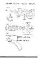
- FIG. 1is a schematic diagram of the microwave radiometer employed in the system of this invention
- FIG. 2is a schematic diagram of the L-band transmitter employed in the system
- FIG. 3shows the body transition element in the form of a hand-held applicator
- FIG. 4is a perspective view of the dual mode antenna and waveguide construction
- FIG. 5is a side view of the waveguide construction depicted in FIG. 4;
- FIG. 6is a graph of frequency response for the bandpass filter of FIG. 1;
- FIG. 7is a graph of transmitter output level associated with the transmitter of FIG. 2.
- FIG. 8is a cross-sectional view of a bronchoscope apparatus adapted to accommodate a different form of applicator in accordance with an endoscopic version of the invention
- FIG. 9is a first embodiment of the radiating element of the endoscopic version.
- FIG. 10is an alternate form of the radiating element of loop-type.
- the microwave system of this inventioncomprises an extremely sensitive passive radiometer capable of measurements of temperature deviations of less than 0.1° C.
- the dual mode microwave systemalso employs a solid state transmitter to provide localized heating of the cancer site.
- the C-band radiometer frequencyis 4.7 GHz and the L-band transmitter frequency is 1.6 GHz.
- the systemalso includes a dual mode antenna comprising a C-band aperture in combination with an L-band applicator.
- the microwave transmittercauses an elevation of the temperature of the tumor above that of the surrounding normal tissue to thus enhance the detection by highlighting the tumor with respect to the surrounding or background tissue.
- the heating of the cancer siteresults in a differential heating of the tumor with respect to the surrounding tissue. Also, because temperatures above about 42° C. are lethal to tumor cells, the system is also applicable for the treatment of cancer.
- the systemis preferably totally battery operated, allowing approximately 8 hours of continuous service prior to requiring a recharging.
- a battery operated systemis employed as it eliminates possible problems associated with line transients, pickup, etc.
- a battery charging circuitis included in the system with an overnight charging cycle being designed to provide the batteries in a fully charged condition for the next day's use.
- Three sealed, maintenance free, lead acid batteriesare connected in series, providing a maximum voltage of 36 volts.
- FIG. 1is a schematic diagram of the microwave radiometer of this invention.
- FIG. 2shows a schematic diagram of the transmitter employed in this system.
- the radiometer and transmitterboth couple to the dual mode antenna with the radiometer receiving its signal from the C-band aperture and the transmitter directing its signal to the L-band applicator. Accordingly, a discussion of the dual mode antenna receives a discussion hereinafter of the radiometer and transmitter schematic diagrams.
- the frequency selected for localized heatingis 1.6 GHz.
- a normal waveguide transition that wold be usedwould have dimensions of 5.100" (12.95 cm) ⁇ 2.550" (6.48 cm). These dimensions correspond to a WR-510 guide.
- a single ridged waveguide constructionis used.
- the use of a ridged waveguidelowers the cutoff frequency allowing use at a lower operating frequency or, in the present situation, allowing the use of a smaller aperture size.
- dielectric loadingis employed.
- the dielectric that is utilizedis preferably aluminum oxide having a relative dielectric constant, e r , of 9.8.
- FIGS. 4 and 5show the dual mode antenna construction which comprises an L-band applicator 10 and a C-band aperture 12.
- the applicator 10as noted in the drawing, is in the form of a single ridge waveguide. This waveguide receives a signal from the probe 14 which couples in turn to the coax line 16. Similarly, there is provided a probe 18 associated with the C-band aperture 12 coupling to an associated coax line 20.
- the ridged waveguide dimenions as identified in FIG. 4,are as follows:
- the insertion lossmay be obtained by measuring the total loss of two identical transitions in series (i.e., mated at the waveguide opening). Assuming the two transitions to be equal in loss, the single transition loss is 0.2 dB maximum.
- the VSWR, when held against the human bodywas approximately 1.5:1. Since the human body does not represent a fixed termination but rather a variable match, a reflectometer is included at the transmitter output to enable determination of the reflected and incident power levels. Both of these measured levels may be easily combined to provide a single output reading.
- the dimensions of the ridged portion of the L-band ridged waveguideare selected to allow propagation of the higher frequency associated with the C-band radiometer.
- the C-band transition or aperturehas dimensions of a height of 0.92 centimeters and a width of 1.83 centimeters.
- the plated surfaces of the dielectric-loaded C-band waveguideform and coincide with the single ridge of the L-band waveguide as depicted in FIG. 4.
- the platingmay be of nickel, copper or gold, for example.
- the insertion lossis measured to be less than 0.3 dB.
- the VSWR, when held against the human bodyis less than 2:1.
- the radiometer input witin the single ridged waveguide L-band transitionBy placing the radiometer input witin the single ridged waveguide L-band transition, the point of maximum field of the source of heat is in close proximity with the point of thermal detection.
- the cutoff characteristics of the C-band waveguideare used along with other filtering to form a highpass filter for isolating the highpower L-band source from the sensitive radiometer.
- a heater 24which is disposed between the applicator and the aperture.
- This heatermay be of conventional design and is in the form of a thin sheet having associated therewith a proportional thermostat for maintaining a constant temperature at or very near to that of the temperature of the human body.
- the microwave assemblyis then contained in an insulated housing 28 having indexing lines 30 on the outer surface as shown in FIG. 3.
- the indexing linesare located 90° apart on the perimeter of the housing to allow accurate positioning of the C-band radiometer input.
- an indexed silk screen and frame(not shown) may be provided. The use of the tightly drawn silk screen allows flattening of the portion of the body to be scanned. The mismatch and loss associated with this thin silk screen is negligible.
- the microwave system of this inventionis also quite safe to use.
- One of the characteristics of the systemis that there is a large mismatch on the order of 12:1 associated with the low impedance ridged waveguide when left open circuited. (i.e., in the atmosphere removed from the human body with its high dielectric constant to which the waveguide is matched).
- the safety standard established by the governmentis 10 mW/cm 2 for electromagnetic radiation, regardless of frequency. For example, microwave ovens are permitted to radiate at a level of 5 mW/cm 2 at a distance of 2" from the oven.
- FIG. 1there is shown a schematic diagram of the microwave radiometer showing the signal coupled from the receiver antenna (C-band aperture) to the switch SW1.
- the microwave radiometer that is depictedis of special design in accordance with the present invention but is generally of the common load comparison, or Dicke, type.
- the radiometer designsubstantially reduces the effects of short term gain fluctuations in the radiometer.
- the receiver inputis switched by means of switch SW1 at a constant rate between the antenna and a constant temperature reference load.
- the switched, or modulated RF signalis therefore inserted at a point prior to RF amplification and as close to the antenna as possible; in turn, it is then amplified and coherently detected.
- the final outputis proportional to the temperature difference between the antenna and the reference load.
- a second switch SW2referred to as a calibration switch, is also employed.
- the reference loadas defined by the noise diode 36 and the fixed attenuator 38, is compared with a base load 40 rather than the signal from the antenna. If the base load is equal in temperature with the reference load, the DC output of the radiometer is thus nulled to zero.
- the radiometer described hereinemploys at least one low noise RF amplifier in conjunction with a simple single-ended square law detector rather than the more complex superheterodyne which employs a local oscillator and IF amplifier.
- the square law detector of this arrangementminimizes the potential drift and noise associated with the superheterodyne approach.
- the components that comprise the radiometerare discussed in detail hereinafter.
- FIG. 1Associated with FIG. 1 is table I set out herein which lists the individual components shown in FIG. 1 along with their identifying part number and brief description of their purpose or function.
- the value of kis 2.0.
- Fnoise figure (first amplifier stage), which in our case is 2.2 dB (1.66 ratio).
- Linput losses, expressed as a power ratio.
- the total lossis 2.0 dB (1.58 ratio).
- the effective noise figure, FLis therefore 2.2+2, or 4.2, which represents a power ratio of 2.63.
- T 1is the ambient radiometer temperature (microwave portion); namely, 290° K.
- the source temperaturei.e., temperature seen by antenna
- the source temperaturei.e., temperature seen by antenna
- the receiver bandwidthi.e., the 3 dB bandwidth of the bandpass filter following the first RF amplifier; namely, 500 MHz.
- the signal level at the input to the square law detector 46 of FIG. 1is determined as follows:
- Fnoise figure (first amplifier stage), which in our case is 2.2 dB (1.66 ratio).
- T oambient temperature of the radiometer, °K.
- the effective noise figure, FLis therefore 2.2+2, or 4.2 dB, which represents a power ratio of 2.63.
- the connectionwhich is preferably by way of a coax cable from the receiver antenna (applicator aperture) to one input of switch SW1.
- switch SW1This may be termed a calibration switch which is a solenoid-operated, mechanical single pole/double-throw switch used to disconnect the antenna and in its place connect the base load 40 by way of a second switch SW2.
- the switch SW1has an isolation, or switching ratio, of grater than 60 dB with a corresponding insertion loss of less than 0.1 dB.
- the switch SW2is used in the calibration circuit to disconnect the base load and to insert in its place the calibrated noise source as represented by the fixed attenuator 38 and the noise diode 36 referred to hereinafter.
- isolators ISOL-1As indicated in FIG. 1, there are three ferrite isolators used in the receiver path. These are identified as isolators ISOL-1, ISOL-2 and ISOL-3.
- the first isolatoris located between the calibration switch SW1 and the Dicke switch SW3. This isolator is used to terminate the output of the reference load when the Dicke switch is in the low loss state. In this state, the reference or base load is circulated in the direction of the antenna which, in this case, functions as a ferrite isolator.
- the isolator ISOL-1employs a coaxial-to-waveguide transition. The insertion loss of this isolator and the transition is less than 0.2 dB, with a corresponding isolation of greater than 23 dB.
- the second isolator ISOL-2 in FIG. 1is disposed between the switch SW3 and the first stage RF amplifier to maintain a constant load match to this amplifier. Any reflections from the RF amplifier would therefore be terminated in the isolator.
- this isolatorwhich is a waveguide isolator with a coax-to-waveguide transition, has an insertion loss of less than 0.2 dB with an isolation of greater than 23 dB.
- FIG. 1There is also provided in FIG. 1 a third isolator ISOL-3 which is located between the output of the first RF amplifier and the bandpass filter 44.
- the purpose of this particular isolatoris to present a constant load match to the output stage of the first RF amplifier, and also to present a matched input to the bandpass filter 44.
- a switchable ferrite circulatordesignated switch SW3 in FIG. 1, forms the load comparison, or Dicke switch, function.
- a ferrite deviceis preferred over a semi-conductor approach primarily in view of the lower insertion loss, typically less than 0.3 dB, and elimination of noise generated by the semi-conductor junction over and above the measured insertion loss.
- the device SW3is a switchable ferrite junction circulator utilizing the remnant, or latching, characteristics of the ferrite material.
- the principle of latching actionis as follows: Using the intrinsic properties of a hysterisis loop of a ferrite toroid, a transverse magnetic field is used across a portion of the ferrite exposed to an RF signal. The biasing field is actually the residual inductance of the ferrite toroid; therefore, the device needs no holding power and can be reversed in polarity using merely enough energy to overcome the natural coercive force of the toroid.
- the latching circulatorhas been constructed in waveguide having a single ferrite element contained within the microwave circuit.
- the insertion lossis less than 0.3 dB, having isolation in excess of 20 dB.
- the first-stage RF amplifiermay be a four stage FET device constructed in microstrip with integrated biasing circuitry.
- the noise figure of the first amplifier(Amplica Model No. 3131CSI) is 2.2 dB with a gain of 35 dB.
- the second RF amplifier(Amplica Model No. 3441CS) has a noise figure of 2.6 dB, with an associated gain of 33 dB.
- the noise figureincludes the input ferrite isolator as depicted in FIG. 1. With the input and output VSWR at less than 1.5:1, the gain compression at signal levels of between -55 dbm to -10 dbm is less than 0.1 dB.
- the filter 44is a bandpass filter and the bandwidth of the microwave radiometer is basically determined by the bandpass characteristics of this filter.
- the filteris disposed after the first stage of RF amplification to minimize the impact of the insertion loss of the filter on the overall system performance.
- the filter characteristicsare chosen to minimize possible interference due to nearby microwave communications or radar bands.
- FIG. 6shows the filter characteristics.
- the filteris preferably an 8-section bandpass filter constructed in stripline.
- the pass band lossis less than 3 dB and the bandwidth is approximately 500 MHz.
- a base load 40an a reference load 42.
- the load designis coaxial, employing a stainless steel RF connector to provide thermal isolation betwen the load and the remainder of the system.
- the coaxial terminationis contained within an insulated housing and utilizes an integrated heater and proportional control to maintain constant temperature. The absolute temperature of both the base and the reference loads is monitored and displayed on a digital temperature indicator (not shown).
- the calibration circuitcomprises a precision, solid state, noise source having an excess noise ratio, ENR of 33 dB. This allows noise to be injected into the receiver front end via the high isolation mechanical calibration switch. The output level of the noise source is reduced through the use of a precision calibrated pad (43.3 dB).
- This calibration circuitis shown in FIG. 1 as including a fixed attenuator 38 and the noise diode 36.
- the temperature sensitivity of the noise diodeis less than 0.01 dB/°C.
- T 1temperature, ambient, of the source; namely, 273.13+22.25° or 295.38° K.
- T 2temperature of component in lossy path; namely, 295.38° C.
- ⁇emissivity or, in this case, excess noise ratio (ENR) of the noise source (33 dB corresponds to a ratio of 1995)
- the lock-in amplifier 50 shown in FIG. 1is one made by Princeton Applied Research, Model No. 5101. This amplifier enables the accurate measurement of signals contaminated by broadband noise, power line pickup, frequency drift or other sources of interference. It accomplishes this by means of an extremely narrow band detector which has the center of its pass band locked to the frequency of the signal to be measured. Because of the frequency lock and narrow bandwidth, large improvements in signal-to-noise ratio are achieved. This allows the signal of interest to be accurately measured, even in situations where it is completely masked by noise.
- the lock-in amplifier 50provides the synchronous function associated with the Dicke switch; i.e., the unit supplies the 100 Hz reference clock frequency to drive the ferrite switch driver.
- the systemis provided, of course, with a power supply comprising three 12-volt, 50 amp. maintenance free, lead-acid batteries in series, fused at 10 amps per battery.
- the outputs from the battery assemblyinclude 12, 24 and 36 volts. These voltages are appropriately applied to the receiver, lock-in amplifier and transmitter.
- Status indicatorsmay be employed for indicating operating voltages.
- the main operating switchmay have three positions including an on position, an off position and a "charged" position. In the charged mole, a meter is used to monitor the charge current to the batteries which is limited to approximately 6 amps. With a 3-9 amp-hour discharge rate (a normal 8 hour operate mode), the recharge cycle is approximately 10-12 hours (overnight).
- the microwave transmitter embodied in the system of this inventionis shown in FIG. 2.
- Thisis an L-band transmitter operating at a frequency of 1.6 GHz.
- the transmitterincludes a 1.6 GHz, 30W, solid state source 60 which couples to an RF power amplifier, filter, and microwave reflectometer.
- There are two series connected filters 66 and 68which are low-pass filters connected in series for providing 120 dB of attenuation at the third harmonic.
- the third harmonic of the 1.6 GHz sourceis 4.8 GHz, which is within the radiometer passband. It is intended that the microwave transmitter operates simultaneously with the microwave radiometer to provide localized heating of subsurface tissue, while simultaneously monitoring the temperature with the radiometer described previously.
- the reflectometer employed in the transmitter of FIG. 2allows determination of both the reflected and incident power levels.
- the detector 70measures the incident leve while the detector 72 measures the reflected level.
- FIG. 2also shows the output terminal 74 which is the RF output coupling to the applicator.
- the output power level from the transmitter of FIG. 2is adjustable from 0 to 25 watts (measured at the input to the L-band antenna) and, therefore, includes all microwave circuit and coaxial cable losses.
- FIG. 7illustrates the approximate power input plotted as a function of "output level" control setting. This measurement is made into a matched load and, therefore, to be more accurate is reduced according to the load mismatch.
- a 2.1 load VSWRfor example, corresponds to a 10% power reflection.
- VSWRvoltage standing wave ratio
- the ratio of the reflected power, P r , to the incident power, P iis determined as follows: ##EQU8## where the total power generated is equal to P r +P i .
- the filter/reflectometer 71 shown in FIG. 2is a microwave integrated circuit such as one by Microwave Associates Model No. MA-56823. This and other parts are identified in the enclosed Table II which shows the primary elements of the transmitter of FIG. 2, their part number and a brief description of their function or purpose.
- the filter/reflectometer assembly 71is depicted as having four ports including an input port 1 and an output port 2.
- the insertion loss from Port 1 to 2is 0.33 dB
- the VSWR of Port 1 and 2is less than 1.15.
- the coupling between Ports 1 and 4 and Ports 2 and 3is approximately 40 dB.
- the coupler associated with Port 4is, therefore, used to measure the reflected power, whereas the coupler associated with Port 3 is used to measure the incident power.
- the directivity of the two couplersis 28 and 16 dB respectively.
- Matched coaxial detectorsHP Model 8472B
- the low pass filters 66 and 68provide third harmonic rejection.
- the attenuation due to the low pass filteringis greater than 60 dB at 4.8 GHz.
- FIG. 5there is a heater 24 depicted in FIG. 5 as used for maintaining the dual mode antenna 10 at a constant temperature close to the human body temperature.
- the heater 24is maintained operating as are heaters associated with the reference load and the base load. This eliminates any need for an extensive "warm-up.”
- the lock-in amplifier 50may have associated therewith certain controls and a meter.
- One of the controlsis a signal sensitivity control.
- the next controlis an offset control which allows zeroing of the meter.
- Another control that may be providedis a time constant pre-filter control which can be normally set in the one or three second position.
- a further controlis a reference control.
- the last controlis a mode selector control.
- controls associated therewithinclude an on-off switch which is used to activate the transmitter and a ten-turn control to adjust the output level.
- a control knoballows adjustment of one of the meters associated with the transmitter to full scale to monitor the applicator efficiency. The ratio between the two meters associated with the transmitter indicates the heater efficiency.
- the dual mode microwave system depicted in FIGS. 4 and 5includes two antennae 10, 12, heater 24, and proportional thermostat not shown in that drawing which is cabled back to the receiver and transmitter.
- the two antennaeare a transmitter antenna or heat antenna and a receiver antenna.
- the heater 24is self-contained within the applicator body and is used to maintain the applicator at body temperature.
- FIG. 5shows schematically the connection of the thermostat between the heater 24 and an electrical source.
- the waveguide constructionsare preferably of a ceramic material such as aluminum oxide with the outer boundaries of the waveguide being formed by means of a metallic plating on the ceramic.
- This platingmay be of nickel, copper or gold.
- This arrangementis depicted in FIG. 4 by a small cut-out portion showing the plating and the ceramic material.
- One of the advantages of the present inventionis that with this system, integrity is maintained between the applicator and the aperture without interference occurring between transmitted heating signals and detected signals. In this way the microwave heating signal can be maintained essentially "on” at all times without any necessity for interruption of this signal for detecting temperature.
- the microwave heating frequencyhas preferably been selected lower than the radiometer frequency as the lower heating frequency provides a deeper penetration of microwave heating.
- the radiometer frequencyis selected higher preferably because at the higher frequency there is an increased resolution which is desired for detecting, in particular, a small temperature differential.
- FIGS. 8, 9 and 10A further embodiment to the present invention is described in FIGS. 8, 9 and 10.
- This embodimentdescribes a microwave endoscope for the internal detection and treatment of cancer.
- This apparatusis used in conjunction with the basic microwave system described hereinbefore to permit detection and/or treatment of internal cancer tissue.
- One of the advantages of the this technique which involves use in conjunction with the endoscopeis the avoidance of high microwave absorption characteristics associated with muscle and other tissue exhibiting high water content when an application is external.
- FIG. 8is a cross-sectional view through a bronchoscope 80 showing fiberoptic light guides 82 and 83 along with an objective lens 84.
- a biopsy forceps channel 86which is adapted to accommodate the system of this invention.
- the bronchoscope with fiberopticsenables an endoscopist to use the biopsy forceps for histodiagnosis.
- the distal end of the bronchoscopehas either one or two fiberoptic light guides which, when connected to a suitable light source, serve to illuminate or transmit light.
- the objective lensis used for viewing.
- the biopsy forceps channelserves as a guide for the biopsy forceps.
- the mechanical positioning of the distal end of the bronchoscopeis conventional and is controlled externally from a known control unit. The control unit and the distal end are connected by a long flexible cable (not shown).
- a microwave transmission linethe end of which is shown in FIG. 9 essentially in the form of a coax cable having an inner conductor 87, an outer conductor 88 and an intermediate dielectric 89.
- This transmission linecouples to a radiating or coupling element two different versions of which are shown in respective FIGS. 9 and 10.
- This transmission line with associated radiating elementis interchangeable with the biopsy forceps for insertion into the biopsy forceps channel 86 of the bronchoscope, proctoscope or other type of similar device adapted for endoscopic work.
- the radiating elementdiscussed in detail hereinafter, is designed to provide efficient coupling of microwave energy to or from the human tissue.
- the endoscopic versionWhen used with a microwave radiometer as described herein before, there is provided accurate measurement of the temperature of the tissue in the vicinity of the radiating element.
- the endoscopic versionis also adapted for use in a dual mode wherein the radiating element is used for the application of heat and thereafter may be used for the detection of temperature.
- the development of this dual mode systemprovides a passive detection technique for use in early detection of cancer.
- the systemhas the capability of providing localized heating of subsurface tissue taking advantage of the differential heating associated with the thermal characteristics of tumors as discussed herein before.
- the human bodyconsists of basically three layers including a thin layer of skin over a thicker layer of subcutaneous fat, in turn over a layer of muscle or other tissue of high water content.
- the pore microwave transmission characteristics associated with the musclei.e., high loss tangent and high dielectric constant
- Coupling in close proximity to the tumoreliminates the problems associated with high transmission losses in the tissue media, allowing greater freedom and selection of frequency. It also allows the use of much lower power levels to achieve the elevated temperature. In this way it is possible to elevate the temperature of the tumor to approximately 50° C. while avoiding increased temperatures is nearby tissues or organs.
- FIG. 9there is shown one embodiment of the radiating element.
- a coaxial lineincluding inner and outer conductors and a central dielectric.
- the inner conductorterminates in a forward end launch 90.
- the outer conductorsconnect to a conductive ring 92 which carries a ceramic end 94.
- the end launch 90is fitted within the ceramic portion of the radiating element.
- the outer ceramic of the elementis preferably polished to prevent injury to the bronchiole wall when the radiating element protrudes from the distal end of the bronchoscope.
- the center conducterprotrudes beyond the end of the outer conductor of the coaxial transmission line to serve as the launch or radiating element both in the embodiment of FIG. 9 and that of FIG. 10.
- the ceramic tipserves as both a mechanical support and guide as well as a matching device.
- the dielectric constant associated with the ceramicresults in a reduced tip size and becomes an integral part of the matching strucure to the human tissue, thereby accomplishing efficient microwave coupling.
- the alternate embodiment of the radiating elementwhich is of loop type is shown in FIG. 10. Again, this element includes inner and outer conductors.
- the inner conductor 87extends in a loop 91 and forms the basic radiating element of the structure. This loop is supported by at least the ceramic portion 93 of the radiating element. The other end 95 of the loop is secured to the conductive ring 92.
- the loop embodiment of the radiating elementsoperates substantially the same as the previously described end launch embodiment.
- the apparatus of the present inventionmay be in particular used for the detection of breast tumors.
- Such tumors having a diameter of less than one cm or approximately 0.5 cmhave been detected.
- Such tumorshave not been capable of detection with normal zero-mammographic techniques.
- the smallest tumormeasured 2.5° C. higher than the surrounding tissue whereas the larger tumor, which was also identified by zero-mannography, measured 1.2° C. higher than the surrounding tissue. This adds credibility to the probability that small tumors are metabolically more active and represent a more concentrated hot spot.
- enhancement of the tumoris provided by the application of heat via the applicator.
- this heatWhen this heat is applied there may initially be a temperature differential between the tumor and the surrounding tissue that is relatively small; that is the differential temperature is reduced.
- a waiting periodoccur which may be approximately five minutes following the application of heat to measure the temperature differential.
- the initial temperature differentialwas 1.2° C.
- the temperature differentialwas then 1.8° C. Due to the improved vascularity of the normal tissue with respect to the tumor, the normal tissue has been found to return to its normal temperature, while the tumor itself remains at an elevated temperature. This demonstrates the ability to enhance detection through application of heat accompanied by a waiting period such as one on the order of five minutes for the actual sensing of temperature.
Landscapes
- Health & Medical Sciences (AREA)
- Life Sciences & Earth Sciences (AREA)
- Engineering & Computer Science (AREA)
- Biomedical Technology (AREA)
- Public Health (AREA)
- Pathology (AREA)
- Veterinary Medicine (AREA)
- Animal Behavior & Ethology (AREA)
- General Health & Medical Sciences (AREA)
- Nuclear Medicine, Radiotherapy & Molecular Imaging (AREA)
- Radiology & Medical Imaging (AREA)
- Physics & Mathematics (AREA)
- Biophysics (AREA)
- Heart & Thoracic Surgery (AREA)
- Medical Informatics (AREA)
- Molecular Biology (AREA)
- Surgery (AREA)
- Radiation Pyrometers (AREA)
Abstract
Description
______________________________________ λg guide wavelength = 26.63 cm λo free space wavelength = 18.64 cm λc cutoff wavelength = 27.89 cm Zo∞ characteristic impedance = 150 ohms at an infinite frequency Zo characteristic impedance = 214 ohms ______________________________________
TABLE I __________________________________________________________________________ITEM PART NO. PURPOSE OR FUNCTION __________________________________________________________________________RECEIVER ANTENNA MA 56825 COAX TO WAVEGUIDE TRANSITION- INTEGRATED WITH TRANSMITTER ANTENNA SWITCH 1 MA 56829 SPDT COAXIAL MECHANICAL SWITCH GREATER THAN 60 dB ISOLATION LESS THAN 0.1 dB LOSS ISOLATOR 1 MA 56831 STRIPLINE FERRITE ISOLATOR WITH INTEGRATED STRIPLINE TO WAVEGUIDE TRANSITION ISOLATOR 2 MA 56834 WAVEGUIDE FERRITE ISOLATOR WITH INTEGRATED TRANSITION TO COAX SWITCH 3 MA 56832 WAVEGUIDE FERRITE LATCHING SWITCH DICKE SWITCH REFERENCE LOAD 42 MA 56836 REFERENCE LOAD COAXIAL TERMINATION WITH INTEGRATED HEATER AND PROPORTIONAL CONTROL BASE LOAD 40 MA 56836 BASE LOAD COAXIAL TERMINATION WITH INTEGRATED HEATER AND PROPORTIONAL CONTROL FIRST RF AMPLIFIER AMPLICA RF AMPLIFIER (FET) HAVING 2.2 dB MODEL NOISE FIGURE AND 35 dB GAIN 3131CS1 ISOLATOR 3 MA 56837 COAXIAL FERRITE ISOLATOR 20 dB MINIMUM ISOLATOR WITH LESS THAN 0.3 dB LOSS FILTER 44 MA 56838 STRIPLINE BANDPASS FILTER 500 MHz BANDWIDTH SECOND RF AMPLIFIER AMPLICA RF AMPLIFIER (FET) HAVING 2.6 dB MODEL NOISE FIGURE AND 33 dB GAIN 3441CS SQUARE LAW DETECTOR MA 56841 FIRST RF DETECTION HAVING AND VIDEO AMPLIFIER 20 dB VIDEO GAIN LOCK IN AMPLIFIER 50 PRINCETON PROVIDES IMPROVED SIGNAL TO APPLIED NOISE RATIO THROUGH FREQUENCY RESEARCH LOCK AND NARROW BANDWIDTH- MODEL PROVIDES SYNCHRONOUS 5101 DETECTION SWITCH 2 MA 56829 SPDT COAXIAL MECHANICAL SWITCH PROVIDING GREATER THAN 60 dB ISOLATION AND LESS THAN 0.1 dB LOSS NOISE DIODE 36 MSC NOISE SOURCE - 30 dB MODEL EXCESS NOISE MC5048 FERRITE SWITCH DRIVER/56 MA 56839 PROVIDES 100 Hz SQUARE WAVE REFERENCE TO LOCK IN AMPLIFIER ALSO PROVIDES LATCHING FERRITE SWITCH DRIVE __________________________________________________________________________
______________________________________ Antenna or Applicator 0.3 dB Cable 0.7 Calibration Switch SW1 0.1 Isolator/Waveguide Adapter 0.3 Dicke Switch SW3 0.3 Ferrite Isolator 0.2 Waveguide-to-Coax Adapter 0.1 2.0 dB (1.58 ratio) ______________________________________
∴NT=(2.63-1)290=473° K.
TABLE II __________________________________________________________________________ITEM PART NO. __________________________________________________________________________1.6 GHz SOURCE MA-56826 THE ENTIRE ASSEMBLY FORMS THE 1.6 GHz SOLID STATE 30W SOURCE. RF POWER AMPLIFIER MA-56829 THE OUTPUT LEVEL IS ELECTRONICALLY VARIABLE. ISOLATOR - FIRST MA-56827 COAXIAL FERRITE ISOLATOR - PROVIDES INTERSTAGE ISOLATION BETWEEN FIRST AND SECOND RF AMPLIFIERS 0.2 dB LOSS, 20 dB MINIMUM ISOLATION ISOLATOR - SECOND MA-56822 COAXIAL FERRITE ISOLATOR - PROVIDES ISOLATION BETWEEN THE SOLID STATE SOURCE AND THE EXTERNAL LOAD FILTER MA-56824 LOW PASS FILTER - PROVIDES THIRD HARMONIC REJECTION OF GREATER THAN 60 dB. FILTER/ MA-56823 LOW PASS FILTER - PROVIDES ADDITIONAL REFLECTOMETER 60 dB THIRD HARMONIC REJECTION. ASSEMBLY COMBUSTION OF DIRECTIONAL COUPLERS AND DETECTOR ALLOWS MEASUREMENT OF FORWARD AND REVERSE POWER. __________________________________________________________________________
Claims (5)
Priority Applications (1)
| Application Number | Priority Date | Filing Date | Title |
|---|---|---|---|
| US06/232,820US4557272A (en) | 1980-03-31 | 1981-02-09 | Microwave endoscope detection and treatment system |
Applications Claiming Priority (2)
| Application Number | Priority Date | Filing Date | Title |
|---|---|---|---|
| US06/135,506US4346716A (en) | 1980-03-31 | 1980-03-31 | Microwave detection system |
| US06/232,820US4557272A (en) | 1980-03-31 | 1981-02-09 | Microwave endoscope detection and treatment system |
Related Parent Applications (1)
| Application Number | Title | Priority Date | Filing Date |
|---|---|---|---|
| US06/135,506Continuation-In-PartUS4346716A (en) | 1980-03-31 | 1980-03-31 | Microwave detection system |
Publications (1)
| Publication Number | Publication Date |
|---|---|
| US4557272Atrue US4557272A (en) | 1985-12-10 |
Family
ID=26833402
Family Applications (1)
| Application Number | Title | Priority Date | Filing Date |
|---|---|---|---|
| US06/232,820Expired - LifetimeUS4557272A (en) | 1980-03-31 | 1981-02-09 | Microwave endoscope detection and treatment system |
Country Status (1)
| Country | Link |
|---|---|
| US (1) | US4557272A (en) |
Cited By (128)
| Publication number | Priority date | Publication date | Assignee | Title |
|---|---|---|---|---|
| US4681122A (en)* | 1985-09-23 | 1987-07-21 | Victory Engineering Corp. | Stereotaxic catheter for microwave thermotherapy |
| US4753248A (en)* | 1987-06-24 | 1988-06-28 | Duke University | Probe translation system for use in hyperthermia treatment |
| US4920978A (en)* | 1988-08-31 | 1990-05-01 | Triangle Research And Development Corporation | Method and apparatus for the endoscopic treatment of deep tumors using RF hyperthermia |
| US5020920A (en)* | 1989-11-03 | 1991-06-04 | The United States Of America As Represented By The United States Department Of Energy | Method and apparatus for millimeter-wave detection of thermal waves for materials evaluation |
| US5044006A (en)* | 1990-04-27 | 1991-08-27 | Cyrulnik Reuven A | Microwave frequency modulation of x-ray beam for radio therapy treatment system |
| US5176146A (en)* | 1989-07-27 | 1993-01-05 | Institut National De La Sante Et De La Recherche Medicale | Method for the measurement of temperatures by microwave radiometry, with automatic calibration of the measurement, and device for operating this method |
| US5445157A (en)* | 1992-02-20 | 1995-08-29 | Asahi Kogaku Kogyo Kabushiki Kaisha | Thermographic endoscope |
| US5628770A (en)* | 1995-06-06 | 1997-05-13 | Urologix, Inc. | Devices for transurethral thermal therapy |
| US5683382A (en)* | 1995-05-15 | 1997-11-04 | Arrow International Investment Corp. | Microwave antenna catheter |
| US5702405A (en)* | 1994-11-30 | 1997-12-30 | Siemens Aktiengesellschaft | Stereotactic auxiliary attachment for a tomography apparatus for tomogram guided implementation of a biopsy |
| US5776176A (en)* | 1996-06-17 | 1998-07-07 | Urologix Inc. | Microwave antenna for arterial for arterial microwave applicator |
| US5815113A (en)* | 1996-08-13 | 1998-09-29 | Trw Inc. | Monolithic, low-noise, synchronous direct detection receiver for passive microwave/millimeter-wave radiometric imaging systems |
| US5843144A (en)* | 1995-06-26 | 1998-12-01 | Urologix, Inc. | Method for treating benign prostatic hyperplasia with thermal therapy |
| US5861021A (en)* | 1996-06-17 | 1999-01-19 | Urologix Inc | Microwave thermal therapy of cardiac tissue |
| US5938692A (en)* | 1996-03-26 | 1999-08-17 | Urologix, Inc. | Voltage controlled variable tuning antenna |
| US5954686A (en)* | 1998-02-02 | 1999-09-21 | Garito; Jon C | Dual-frequency electrosurgical instrument |
| US6064903A (en)* | 1997-12-29 | 2000-05-16 | Spectra Research, Inc. | Electromagnetic detection of an embedded dielectric region within an ambient dielectric region |
| US6067475A (en)* | 1998-11-05 | 2000-05-23 | Urologix, Inc. | Microwave energy delivery system including high performance dual directional coupler for precisely measuring forward and reverse microwave power during thermal therapy |
| US6200333B1 (en) | 1997-04-07 | 2001-03-13 | Broncus Technologies, Inc. | Bronchial stenter |
| US6210367B1 (en) | 1995-09-06 | 2001-04-03 | Microwave Medical Systems, Inc. | Intracorporeal microwave warming method and apparatus |
| US6273907B1 (en)* | 1997-04-07 | 2001-08-14 | Broncus Technologies, Inc. | Bronchial stenter |
| US6283989B1 (en) | 1997-04-07 | 2001-09-04 | Broncus Technolgies, Inc. | Method of treating a bronchial tube with a bronchial stenter having diametrically adjustable electrodes |
| US6283988B1 (en) | 1997-04-07 | 2001-09-04 | Broncus Technologies, Inc. | Bronchial stenter having expandable electrodes |
| US6424869B1 (en)* | 1995-09-06 | 2002-07-23 | Meridian Medical Systems, Llc | Dual mode transurethral microwave warming apparatus |
| US6488673B1 (en) | 1997-04-07 | 2002-12-03 | Broncus Technologies, Inc. | Method of increasing gas exchange of a lung |
| US6496738B2 (en)* | 1995-09-06 | 2002-12-17 | Kenneth L. Carr | Dual frequency microwave heating apparatus |
| US20030109862A1 (en)* | 2001-11-02 | 2003-06-12 | Mani Prakash | High-strength microwave antenna assemblies and methods of use |
| WO2003082090A1 (en)* | 2002-03-28 | 2003-10-09 | The University Court Of The University Of St Andrews | Medical imaging apparatus |
| WO2003088858A1 (en)* | 2002-04-16 | 2003-10-30 | Vivant Medical, Inc. | Microwave antenna having a curved configuration |
| US20040167517A1 (en)* | 2001-06-07 | 2004-08-26 | Kai Desinger | Probe arrangement |
| US20040249272A1 (en)* | 2003-06-02 | 2004-12-09 | Carr Kenneth L. | Microwave detection apparatus |
| US20040267115A1 (en)* | 2003-06-25 | 2004-12-30 | Carr Kenneth L. | Method and apparatus for measuring intravascular blood flow |
| US20050062666A1 (en)* | 2001-11-02 | 2005-03-24 | Vivant Medical, Inc. | High-strength microwave antenna assemblies |
| US20050122254A1 (en)* | 2003-09-18 | 2005-06-09 | Xytrans, Inc. | Multi-channel radiometer imaging system |
| US20050149010A1 (en)* | 2003-07-18 | 2005-07-07 | Vivant Medical, Inc. | Devices and methods for cooling microwave antennas |
| US20050190815A1 (en)* | 2003-10-16 | 2005-09-01 | Samsung Electronics Co., Ltd. | Radio-thermometer system and method for measuring electromagnetic energy radiated from an interior of a human body using the same |
| WO2006002943A1 (en)* | 2004-07-02 | 2006-01-12 | Microsulis Limited | Radiation applicator and method of radiating tissue |
| US20060022662A1 (en)* | 2004-07-14 | 2006-02-02 | Xytrans, Inc. | Switched measuring system and method for measuring radiant signals |
| US7034516B2 (en) | 2003-09-18 | 2006-04-25 | Xytrans, Inc. | Multi-channel radiometer imaging system |
| US20060189973A1 (en)* | 2004-04-29 | 2006-08-24 | Van Der Weide Daniel W | Segmented catheter for tissue ablation |
| US7160292B2 (en) | 1999-06-17 | 2007-01-09 | Vivant Medical, Inc. | Needle kit and method for microwave ablation, track coagulation, and biopsy |
| US20070016181A1 (en)* | 2004-04-29 | 2007-01-18 | Van Der Weide Daniel W | Microwave tissue resection tool |
| US20070049918A1 (en)* | 2005-08-24 | 2007-03-01 | Van Der Weide Daniel W | Microwave device for vascular ablation |
| US7217245B1 (en)* | 1999-04-15 | 2007-05-15 | University Of Utah Research Foundation | Noninvasive methods for detecting abnormalities in a subject such as disease or dysfunction |
| US20070185554A1 (en)* | 2006-02-07 | 2007-08-09 | Angiodynamics, Inc. | Interstitial microwave system and method for thermal treatment of diseases |
| US7264002B2 (en) | 1998-06-10 | 2007-09-04 | Asthmatx, Inc. | Methods of treating reversible obstructive pulmonary disease |
| US20070219548A1 (en)* | 2006-03-16 | 2007-09-20 | Carr Kenneth L | Microwave apparatus for controlled tissue ablation |
| US20070282190A1 (en)* | 2006-06-01 | 2007-12-06 | D.P. Electronic Systems Ltd. | Method Of Infrared Thermography For Earlier Diagnosis Of Gastric Colorectal And Cervical Cancer |
| US20070282319A1 (en)* | 2006-03-24 | 2007-12-06 | Micrablate, Inc. | Center fed dipole for use with tissue ablation systems, devices and methods |
| US20080033424A1 (en)* | 2006-03-24 | 2008-02-07 | Micrablate | Transmission line with heat transfer ability |
| US20080045938A1 (en)* | 2006-07-14 | 2008-02-21 | Micrablate | Energy delivery systems and uses thereof |
| US20080294155A1 (en)* | 2006-01-03 | 2008-11-27 | Microsulis House | Radiation Applicator and Method of Radiating Tissue |
| US7468042B2 (en) | 2002-04-16 | 2008-12-23 | Vivant Medical, Inc. | Localization element with energized tip |
| US20090084581A1 (en)* | 2007-09-28 | 2009-04-02 | Vivant Medical, Inc. | Cable Stand-Off |
| US7603088B2 (en) | 2003-09-18 | 2009-10-13 | Reveal Imaging, Llc | Multi-channel radiometer imaging system and MMIC chips for use thereof |
| US20100076424A1 (en)* | 2006-06-26 | 2010-03-25 | Carr Kenneth L | Radiometric heating/sensing probe |
| US7740017B2 (en) | 1997-04-07 | 2010-06-22 | Asthmatx, Inc. | Method for treating an asthma attack |
| US20100222699A1 (en)* | 2009-02-27 | 2010-09-02 | Turnquist Douglas G | Method for monitoring internal tissue |
| US7799019B2 (en) | 2005-05-10 | 2010-09-21 | Vivant Medical, Inc. | Reinforced high strength microwave antenna |
| US7837679B2 (en) | 2000-10-17 | 2010-11-23 | Asthmatx, Inc. | Control system and process for application of energy to airway walls and other mediums |
| US20110077636A1 (en)* | 2009-09-29 | 2011-03-31 | Vivant Medical, Inc. | Management of Voltage Standing Wave Ratio at Skin Surface During Microwave Ablation |
| US7921855B2 (en) | 1998-01-07 | 2011-04-12 | Asthmatx, Inc. | Method for treating an asthma attack |
| US20110130800A1 (en)* | 2009-12-01 | 2011-06-02 | Kyma Medical Technologies Ltd | Microwave Monitoring of Heart Function |
| US7992572B2 (en) | 1998-06-10 | 2011-08-09 | Asthmatx, Inc. | Methods of evaluating individuals having reversible obstructive pulmonary disease |
| US7998139B2 (en) | 2007-04-25 | 2011-08-16 | Vivant Medical, Inc. | Cooled helical antenna for microwave ablation |
| US8059059B2 (en) | 2008-05-29 | 2011-11-15 | Vivant Medical, Inc. | Slidable choke microwave antenna |
| ITRM20100252A1 (en)* | 2010-05-17 | 2011-11-18 | Consiglio Nazionale Ricerche | MICROWAVE SURGICAL DEVICE |
| US8068921B2 (en) | 2006-09-29 | 2011-11-29 | Vivant Medical, Inc. | Microwave antenna assembly and method of using the same |
| US20110295247A1 (en)* | 2010-05-28 | 2011-12-01 | Hansen Medical, Inc. | System and method for automated minimally invasive therapy using radiometry |
| US8181656B2 (en) | 1998-06-10 | 2012-05-22 | Asthmatx, Inc. | Methods for treating airways |
| US8251070B2 (en) | 2000-03-27 | 2012-08-28 | Asthmatx, Inc. | Methods for treating airways |
| US8257413B2 (en) | 2000-10-17 | 2012-09-04 | Asthmatx, Inc. | Modification of airways by application of energy |
| US8292880B2 (en) | 2007-11-27 | 2012-10-23 | Vivant Medical, Inc. | Targeted cooling of deployable microwave antenna |
| US8353901B2 (en) | 2007-05-22 | 2013-01-15 | Vivant Medical, Inc. | Energy delivery conduits for use with electrosurgical devices |
| US8483831B1 (en) | 2008-02-15 | 2013-07-09 | Holaira, Inc. | System and method for bronchial dilation |
| US20130345692A1 (en)* | 2012-06-22 | 2013-12-26 | Covidien Lp | Microwave thermometry for microwave ablation systems |
| US8740895B2 (en) | 2009-10-27 | 2014-06-03 | Holaira, Inc. | Delivery devices with coolable energy emitting assemblies |
| US20140187930A1 (en)* | 2012-12-28 | 2014-07-03 | Sony Corporation | Microwave transmission device and microwave transmission system |
| US8808280B2 (en) | 2008-05-09 | 2014-08-19 | Holaira, Inc. | Systems, assemblies, and methods for treating a bronchial tree |
| US8911439B2 (en) | 2009-11-11 | 2014-12-16 | Holaira, Inc. | Non-invasive and minimally invasive denervation methods and systems for performing the same |
| US8926605B2 (en) | 2012-02-07 | 2015-01-06 | Advanced Cardiac Therapeutics, Inc. | Systems and methods for radiometrically measuring temperature during tissue ablation |
| US8939914B2 (en) | 2009-02-27 | 2015-01-27 | Thermimage, Inc. | Radiometers and related devices and methods |
| US8954161B2 (en) | 2012-06-01 | 2015-02-10 | Advanced Cardiac Therapeutics, Inc. | Systems and methods for radiometrically measuring temperature and detecting tissue contact prior to and during tissue ablation |
| US8961506B2 (en) | 2012-03-12 | 2015-02-24 | Advanced Cardiac Therapeutics, Inc. | Methods of automatically regulating operation of ablation members based on determined temperatures |
| US9023024B2 (en) | 2007-06-20 | 2015-05-05 | Covidien Lp | Reflective power monitoring for microwave applications |
| US9119649B2 (en) | 2009-07-28 | 2015-09-01 | Neuwave Medical, Inc. | Energy delivery systems and uses thereof |
| WO2015143325A1 (en)* | 2014-03-21 | 2015-09-24 | Meridian Medical Systems, Llc | Treatment of barrett's esophagus incorporating radiometric sensing |
| US9149328B2 (en) | 2009-11-11 | 2015-10-06 | Holaira, Inc. | Systems, apparatuses, and methods for treating tissue and controlling stenosis |
| EP2942005A1 (en) | 2006-06-26 | 2015-11-11 | Meridian Medical Systems, LLC | Integrated heating/sensing catheter apparatus for minimally invasive applications |
| US9192438B2 (en) | 2011-12-21 | 2015-11-24 | Neuwave Medical, Inc. | Energy delivery systems and uses thereof |
| US9220420B2 (en) | 2010-07-21 | 2015-12-29 | Kyma Medical Technologies Ltd. | Implantable dielectrometer |
| US9265438B2 (en) | 2008-05-27 | 2016-02-23 | Kyma Medical Technologies Ltd. | Locating features in the heart using radio frequency imaging |
| US9272132B2 (en) | 2012-11-02 | 2016-03-01 | Boston Scientific Scimed, Inc. | Medical device for treating airways and related methods of use |
| US9277961B2 (en) | 2009-06-12 | 2016-03-08 | Advanced Cardiac Therapeutics, Inc. | Systems and methods of radiometrically determining a hot-spot temperature of tissue being treated |
| US9283374B2 (en) | 2012-11-05 | 2016-03-15 | Boston Scientific Scimed, Inc. | Devices and methods for delivering energy to body lumens |
| US9339618B2 (en) | 2003-05-13 | 2016-05-17 | Holaira, Inc. | Method and apparatus for controlling narrowing of at least one airway |
| US9398933B2 (en) | 2012-12-27 | 2016-07-26 | Holaira, Inc. | Methods for improving drug efficacy including a combination of drug administration and nerve modulation |
| US20160345896A1 (en)* | 2014-02-06 | 2016-12-01 | Meridian Medical Systems, Llc | System for identifying tissue characteristics or properties utilizing radiometric sensing |
| US9510905B2 (en) | 2014-11-19 | 2016-12-06 | Advanced Cardiac Therapeutics, Inc. | Systems and methods for high-resolution mapping of tissue |
| US9517103B2 (en) | 2014-11-19 | 2016-12-13 | Advanced Cardiac Therapeutics, Inc. | Medical instruments with multiple temperature sensors |
| US9522033B2 (en) | 2012-10-02 | 2016-12-20 | Covidien Lp | Devices and methods for optical detection of tissue contact |
| US9592086B2 (en) | 2012-07-24 | 2017-03-14 | Boston Scientific Scimed, Inc. | Electrodes for tissue treatment |
| US9636164B2 (en) | 2015-03-25 | 2017-05-02 | Advanced Cardiac Therapeutics, Inc. | Contact sensing systems and methods |
| US9668802B2 (en) | 2012-10-02 | 2017-06-06 | Covidien Lp | Devices and methods for optical detection of tissue contact |
| US9770293B2 (en) | 2012-06-04 | 2017-09-26 | Boston Scientific Scimed, Inc. | Systems and methods for treating tissue of a passageway within a body |
| US9861440B2 (en) | 2010-05-03 | 2018-01-09 | Neuwave Medical, Inc. | Energy delivery systems and uses thereof |
| US20180058945A1 (en)* | 2015-12-22 | 2018-03-01 | Limited Liability Company "Rtm Diagnostics" | Microwave radiometer |
| US9993178B2 (en) | 2016-03-15 | 2018-06-12 | Epix Therapeutics, Inc. | Methods of determining catheter orientation |
| US10166062B2 (en) | 2014-11-19 | 2019-01-01 | Epix Therapeutics, Inc. | High-resolution mapping of tissue with pacing |
| US10368404B2 (en) | 2014-03-21 | 2019-07-30 | Whirlpool Corporation | Solid-state microwave device |
| US10376314B2 (en) | 2006-07-14 | 2019-08-13 | Neuwave Medical, Inc. | Energy delivery systems and uses thereof |
| US10478247B2 (en) | 2013-08-09 | 2019-11-19 | Boston Scientific Scimed, Inc. | Expandable catheter and related methods of manufacture and use |
| US10492849B2 (en) | 2013-03-15 | 2019-12-03 | Cynosure, Llc | Surgical instruments and systems with multimodes of treatments and electrosurgical operation |
| US10531917B2 (en) | 2016-04-15 | 2020-01-14 | Neuwave Medical, Inc. | Systems and methods for energy delivery |
| US10548485B2 (en) | 2015-01-12 | 2020-02-04 | Zoll Medical Israel Ltd. | Systems, apparatuses and methods for radio frequency-based attachment sensing |
| WO2020049283A1 (en)* | 2018-09-05 | 2020-03-12 | Emblation Limited | Microwave apparatus, system and manufacturing method |
| US10680324B2 (en) | 2013-10-29 | 2020-06-09 | Zoll Medical Israel Ltd. | Antenna systems and devices and methods of manufacture thereof |
| US10888373B2 (en) | 2017-04-27 | 2021-01-12 | Epix Therapeutics, Inc. | Contact assessment between an ablation catheter and tissue |
| US10952792B2 (en) | 2015-10-26 | 2021-03-23 | Neuwave Medical, Inc. | Energy delivery systems and uses thereof |
| US11013420B2 (en) | 2014-02-05 | 2021-05-25 | Zoll Medical Israel Ltd. | Systems, apparatuses and methods for determining blood pressure |
| US11020002B2 (en) | 2017-08-10 | 2021-06-01 | Zoll Medical Israel Ltd. | Systems, devices and methods for physiological monitoring of patients |
| US11259715B2 (en) | 2014-09-08 | 2022-03-01 | Zoll Medical Israel Ltd. | Monitoring and diagnostics systems and methods |
| US11357568B2 (en)* | 2014-11-19 | 2022-06-14 | Epix Therapeutics, Inc. | Radiometric tissue contact and tissue type detection |
| US11672596B2 (en) | 2018-02-26 | 2023-06-13 | Neuwave Medical, Inc. | Energy delivery devices with flexible and adjustable tips |
| US11819259B2 (en) | 2018-02-07 | 2023-11-21 | Cynosure, Inc. | Methods and apparatus for controlled RF treatments and RF generator system |
| USD1005484S1 (en) | 2019-07-19 | 2023-11-21 | Cynosure, Llc | Handheld medical instrument and docking base |
| US11832879B2 (en) | 2019-03-08 | 2023-12-05 | Neuwave Medical, Inc. | Systems and methods for energy delivery |
| EP4382063A4 (en)* | 2021-08-04 | 2024-10-16 | Nikkiso Co., Ltd. | MICROWAVE OVEN |
Citations (14)
| Publication number | Priority date | Publication date | Assignee | Title |
|---|---|---|---|---|
| US2407690A (en)* | 1941-05-16 | 1946-09-17 | Bell Telephone Labor Inc | Wave guide electrotherapeutic system |
| GB862646A (en)* | 1957-03-22 | 1961-03-15 | Zeiss Jena Veb Carl | Improvements in therapeutic micro-wave systems |
| DE1130534B (en)* | 1960-04-08 | 1962-05-30 | Philips Patentverwaltung | Rod emitters for medical treatment purposes |
| US3065752A (en)* | 1959-11-14 | 1962-11-27 | Philips Corp | High frequency therapeutic radiator |
| DE1145279B (en)* | 1960-02-18 | 1963-03-14 | Mikrowellen Ges M B H Deutsche | Contact electrode for the therapeutic treatment of locally limited organic tissue volumes |
| US3810459A (en)* | 1972-04-27 | 1974-05-14 | American Optical Corp | Transcutaneous blood vessel probe with relocation marker |
| US3858586A (en)* | 1971-03-11 | 1975-01-07 | Martin Lessen | Surgical method and electrode therefor |
| DE2815156A1 (en)* | 1977-04-08 | 1978-10-19 | Cgr Mev | ARRANGEMENT FOR LOCAL WARMING OF LIVING TISSUE BY ELECTROMAGNETIC WAVES OF HIGH FREQUENCY FOR MEDICAL APPLICATIONS |
| US4138998A (en)* | 1976-08-18 | 1979-02-13 | Rca Corporation | Indicating temperature within living tissue |
| US4154246A (en)* | 1977-07-25 | 1979-05-15 | Leveen Harry H | Field intensification in radio frequency thermotherapy |
| US4269199A (en)* | 1979-03-14 | 1981-05-26 | Harry H. Leveen | Inducing local hyperthermia by inductive diathermy |
| US4311154A (en)* | 1979-03-23 | 1982-01-19 | Rca Corporation | Nonsymmetrical bulb applicator for hyperthermic treatment of the body |
| US4346716A (en)* | 1980-03-31 | 1982-08-31 | M/A Com, Inc. | Microwave detection system |
| US4409993A (en)* | 1980-07-23 | 1983-10-18 | Olympus Optical Co., Ltd. | Endoscope apparatus |
- 1981
- 1981-02-09USUS06/232,820patent/US4557272A/ennot_activeExpired - Lifetime
Patent Citations (15)
| Publication number | Priority date | Publication date | Assignee | Title |
|---|---|---|---|---|
| US2407690A (en)* | 1941-05-16 | 1946-09-17 | Bell Telephone Labor Inc | Wave guide electrotherapeutic system |
| GB862646A (en)* | 1957-03-22 | 1961-03-15 | Zeiss Jena Veb Carl | Improvements in therapeutic micro-wave systems |
| US3065752A (en)* | 1959-11-14 | 1962-11-27 | Philips Corp | High frequency therapeutic radiator |
| DE1145279B (en)* | 1960-02-18 | 1963-03-14 | Mikrowellen Ges M B H Deutsche | Contact electrode for the therapeutic treatment of locally limited organic tissue volumes |
| DE1130534B (en)* | 1960-04-08 | 1962-05-30 | Philips Patentverwaltung | Rod emitters for medical treatment purposes |
| US3858586A (en)* | 1971-03-11 | 1975-01-07 | Martin Lessen | Surgical method and electrode therefor |
| US3810459A (en)* | 1972-04-27 | 1974-05-14 | American Optical Corp | Transcutaneous blood vessel probe with relocation marker |
| US4138998A (en)* | 1976-08-18 | 1979-02-13 | Rca Corporation | Indicating temperature within living tissue |
| DE2815156A1 (en)* | 1977-04-08 | 1978-10-19 | Cgr Mev | ARRANGEMENT FOR LOCAL WARMING OF LIVING TISSUE BY ELECTROMAGNETIC WAVES OF HIGH FREQUENCY FOR MEDICAL APPLICATIONS |
| US4312364A (en)* | 1977-04-08 | 1982-01-26 | C.G.R. Mev | Apparatus for localized heating of a living tissue, using electromagnetic waves of ultra high frequency, for medical applications |
| US4154246A (en)* | 1977-07-25 | 1979-05-15 | Leveen Harry H | Field intensification in radio frequency thermotherapy |
| US4269199A (en)* | 1979-03-14 | 1981-05-26 | Harry H. Leveen | Inducing local hyperthermia by inductive diathermy |
| US4311154A (en)* | 1979-03-23 | 1982-01-19 | Rca Corporation | Nonsymmetrical bulb applicator for hyperthermic treatment of the body |
| US4346716A (en)* | 1980-03-31 | 1982-08-31 | M/A Com, Inc. | Microwave detection system |
| US4409993A (en)* | 1980-07-23 | 1983-10-18 | Olympus Optical Co., Ltd. | Endoscope apparatus |
Non-Patent Citations (16)
| Title |
|---|
| Barrett, A. H. et al., "Sub-Cutaneous Temps: A Method of Non-Invasive Sensing", Science, vol. 190, Nov. 1975, pp. 669-671. |
| Barrett, A. H. et al., Sub Cutaneous Temps: A Method of Non Invasive Sensing , Science, vol. 190, Nov. 1975, pp. 669 671.* |
| Dickson, J. A. et al., "Tumor Eradication in the Rabbit by RF Heating", Cancer Research 37, 2162-2169, Jul. 1977. |
| Dickson, J. A. et al., Tumor Eradication in the Rabbit by RF Heating , Cancer Research 37, 2162 2169, Jul. 1977.* |
| Ely, T. S. et al., "Heating Characteristic of Lab Animals Exposed to Microwaves", IEEE BME Transactions, Oct., 1964. |
| Ely, T. S. et al., Heating Characteristic of Lab Animals Exposed to Microwaves , IEEE BME Transactions, Oct., 1964.* |
| Griffin, D. W., "MW Interferometer for Biological Studies", Microwave Jrnl., vol. 21, May 1978, pp. 69-71. |
| Griffin, D. W., MW Interferometer for Biological Studies , Microwave Jrnl., vol. 21, May 1978, pp. 69 71.* |
| Larsen, L. et al., "A Microwave Decoupled Brain Temperature Transducer", IEEE Trans. on Microwave Theory & Techniques, vol. MTT-22, No. 4, pp. 438-444 (Apr. 1974). |
| Larsen, L. et al., A Microwave Decoupled Brain Temperature Transducer , IEEE Trans. on Microwave Theory & Techniques, vol. MTT 22, No. 4, pp. 438 444 (Apr. 1974).* |
| Lenox, R. H. "A Microwave Applicator for In Vivo Rapid Inactivation of Enzymes in the Central Nervous System", IEEE Trans. on M-Wave Theory & Tech. vol. MTT-24 #1, pp. 58-61, Jan. 1976. |
| Lenox, R. H. A Microwave Applicator for In Vivo Rapid Inactivation of Enzymes in the Central Nervous System , IEEE Trans. on M Wave Theory & Tech. vol. MTT 24 1, pp. 58 61, Jan. 1976.* |
| Mendecki, T. et al., "M-Wave Applicators for Localized Hyperthermia Rx of Cancer of the Prostate", Int. Jrnl. Rad. Oncology, vol. 6 #11, pp. 1583-1588, Nov. 1980. |
| Mendecki, T. et al., M Wave Applicators for Localized Hyperthermia Rx of Cancer of the Prostate , Int. Jrnl. Rad. Oncology, vol. 6 11, pp. 1583 1588, Nov. 1980.* |
| Sterzer, F., "Apparatus for Hyperthermia Treatment", PCT GB2000335 A (UK Patent Appl.) Jan. 4, 1979. |
| Sterzer, F., Apparatus for Hyperthermia Treatment , PCT GB2000335 A (UK Patent Appl.) Jan. 4, 1979.* |
Cited By (354)
| Publication number | Priority date | Publication date | Assignee | Title |
|---|---|---|---|---|
| US4681122A (en)* | 1985-09-23 | 1987-07-21 | Victory Engineering Corp. | Stereotaxic catheter for microwave thermotherapy |
| US4753248A (en)* | 1987-06-24 | 1988-06-28 | Duke University | Probe translation system for use in hyperthermia treatment |
| US4920978A (en)* | 1988-08-31 | 1990-05-01 | Triangle Research And Development Corporation | Method and apparatus for the endoscopic treatment of deep tumors using RF hyperthermia |
| US5176146A (en)* | 1989-07-27 | 1993-01-05 | Institut National De La Sante Et De La Recherche Medicale | Method for the measurement of temperatures by microwave radiometry, with automatic calibration of the measurement, and device for operating this method |
| US5020920A (en)* | 1989-11-03 | 1991-06-04 | The United States Of America As Represented By The United States Department Of Energy | Method and apparatus for millimeter-wave detection of thermal waves for materials evaluation |
| US5044006A (en)* | 1990-04-27 | 1991-08-27 | Cyrulnik Reuven A | Microwave frequency modulation of x-ray beam for radio therapy treatment system |
| WO1991016948A1 (en)* | 1990-04-27 | 1991-11-14 | Reuven Avrahom Cyrulnik | Selective radiation of pathological material |
| JP3191875B2 (en) | 1990-04-27 | 2001-07-23 | サイリュルニック,リューベン・アブラハム | Selective radiation to pathological substances |
| US5445157A (en)* | 1992-02-20 | 1995-08-29 | Asahi Kogaku Kogyo Kabushiki Kaisha | Thermographic endoscope |
| US5702405A (en)* | 1994-11-30 | 1997-12-30 | Siemens Aktiengesellschaft | Stereotactic auxiliary attachment for a tomography apparatus for tomogram guided implementation of a biopsy |
| US5683382A (en)* | 1995-05-15 | 1997-11-04 | Arrow International Investment Corp. | Microwave antenna catheter |
| US5628770A (en)* | 1995-06-06 | 1997-05-13 | Urologix, Inc. | Devices for transurethral thermal therapy |
| US5843144A (en)* | 1995-06-26 | 1998-12-01 | Urologix, Inc. | Method for treating benign prostatic hyperplasia with thermal therapy |
| US6496738B2 (en)* | 1995-09-06 | 2002-12-17 | Kenneth L. Carr | Dual frequency microwave heating apparatus |
| US6424869B1 (en)* | 1995-09-06 | 2002-07-23 | Meridian Medical Systems, Llc | Dual mode transurethral microwave warming apparatus |
| US6210367B1 (en) | 1995-09-06 | 2001-04-03 | Microwave Medical Systems, Inc. | Intracorporeal microwave warming method and apparatus |
| US5938692A (en)* | 1996-03-26 | 1999-08-17 | Urologix, Inc. | Voltage controlled variable tuning antenna |
| US6032078A (en)* | 1996-03-26 | 2000-02-29 | Urologix, Inc. | Voltage controlled variable tuning antenna |
| US5776176A (en)* | 1996-06-17 | 1998-07-07 | Urologix Inc. | Microwave antenna for arterial for arterial microwave applicator |
| US5861021A (en)* | 1996-06-17 | 1999-01-19 | Urologix Inc | Microwave thermal therapy of cardiac tissue |
| US6052024A (en)* | 1996-08-13 | 2000-04-18 | Trw Inc. | Monolithic, low-noise, synchronous direct detection receiver for passive microwave/millimeter-wave radiometric imaging systems |
| US5815113A (en)* | 1996-08-13 | 1998-09-29 | Trw Inc. | Monolithic, low-noise, synchronous direct detection receiver for passive microwave/millimeter-wave radiometric imaging systems |
| US7740017B2 (en) | 1997-04-07 | 2010-06-22 | Asthmatx, Inc. | Method for treating an asthma attack |
| US7770584B2 (en) | 1997-04-07 | 2010-08-10 | Asthmatx, Inc. | Modification of airways by application of microwave energy |
| US6273907B1 (en)* | 1997-04-07 | 2001-08-14 | Broncus Technologies, Inc. | Bronchial stenter |
| US6283989B1 (en) | 1997-04-07 | 2001-09-04 | Broncus Technolgies, Inc. | Method of treating a bronchial tube with a bronchial stenter having diametrically adjustable electrodes |
| US6283988B1 (en) | 1997-04-07 | 2001-09-04 | Broncus Technologies, Inc. | Bronchial stenter having expandable electrodes |
| US6299633B1 (en) | 1997-04-07 | 2001-10-09 | Broncus Technologies, Inc. | Bronchial stenter |
| US6200333B1 (en) | 1997-04-07 | 2001-03-13 | Broncus Technologies, Inc. | Bronchial stenter |
| US6488673B1 (en) | 1997-04-07 | 2002-12-03 | Broncus Technologies, Inc. | Method of increasing gas exchange of a lung |
| US8640711B2 (en) | 1997-04-07 | 2014-02-04 | Asthmatx, Inc. | Method for treating an asthma attack |
| US11033317B2 (en) | 1997-04-07 | 2021-06-15 | Boston Scientific Scimed, Inc. | Methods for treating a lung |
| US7556624B2 (en) | 1997-04-07 | 2009-07-07 | Asthmatx, Inc. | Method of increasing gas exchange of a lung |
| US8267094B2 (en) | 1997-04-07 | 2012-09-18 | Asthmatx, Inc. | Modification of airways by application of ultrasound energy |
| US9956023B2 (en) | 1997-04-07 | 2018-05-01 | Boston Scientific Scimed, Inc. | System for treating a lung |
| US10058370B2 (en) | 1997-04-07 | 2018-08-28 | Boston Scientific Scimed, Inc. | Method for treating a lung |
| US8161978B2 (en) | 1997-04-07 | 2012-04-24 | Asthmatx, Inc. | Methods for treating asthma by damaging nerve tissue |
| US8944071B2 (en) | 1997-04-07 | 2015-02-03 | Asthmatx, Inc. | Method for treating an asthma attack |
| US7938123B2 (en) | 1997-04-07 | 2011-05-10 | Asthmatx, Inc. | Modification of airways by application of cryo energy |
| US9027564B2 (en) | 1997-04-07 | 2015-05-12 | Asthmatx, Inc. | Method for treating a lung |
| US6064903A (en)* | 1997-12-29 | 2000-05-16 | Spectra Research, Inc. | Electromagnetic detection of an embedded dielectric region within an ambient dielectric region |
| US7921855B2 (en) | 1998-01-07 | 2011-04-12 | Asthmatx, Inc. | Method for treating an asthma attack |
| US9789331B2 (en) | 1998-01-07 | 2017-10-17 | Boston Scientific Scimed, Inc. | Methods of treating a lung |
| US8584681B2 (en) | 1998-01-07 | 2013-11-19 | Asthmatx, Inc. | Method for treating an asthma attack |
| US5954686A (en)* | 1998-02-02 | 1999-09-21 | Garito; Jon C | Dual-frequency electrosurgical instrument |
| US8181656B2 (en) | 1998-06-10 | 2012-05-22 | Asthmatx, Inc. | Methods for treating airways |
| US7273055B2 (en) | 1998-06-10 | 2007-09-25 | Asthmatx, Inc. | Methods of treating asthma |
| US8534291B2 (en) | 1998-06-10 | 2013-09-17 | Asthmatx, Inc. | Methods of treating inflammation in airways |
| US7264002B2 (en) | 1998-06-10 | 2007-09-04 | Asthmatx, Inc. | Methods of treating reversible obstructive pulmonary disease |
| US8733367B2 (en) | 1998-06-10 | 2014-05-27 | Asthmatx, Inc. | Methods of treating inflammation in airways |
| US7542802B2 (en) | 1998-06-10 | 2009-06-02 | Asthmatx, Inc. | Methods of regenerating tissue in airways |
| US8443810B2 (en) | 1998-06-10 | 2013-05-21 | Asthmatx, Inc. | Methods of reducing mucus in airways |
| US8464723B2 (en) | 1998-06-10 | 2013-06-18 | Asthmatx, Inc. | Methods of evaluating individuals having reversible obstructive pulmonary disease |
| US7992572B2 (en) | 1998-06-10 | 2011-08-09 | Asthmatx, Inc. | Methods of evaluating individuals having reversible obstructive pulmonary disease |
| US6067475A (en)* | 1998-11-05 | 2000-05-23 | Urologix, Inc. | Microwave energy delivery system including high performance dual directional coupler for precisely measuring forward and reverse microwave power during thermal therapy |
| US7217245B1 (en)* | 1999-04-15 | 2007-05-15 | University Of Utah Research Foundation | Noninvasive methods for detecting abnormalities in a subject such as disease or dysfunction |
| US8690868B2 (en) | 1999-06-17 | 2014-04-08 | Covidien Lp | Needle kit and method for microwave ablation, track coagulation, and biopsy |
| US7160292B2 (en) | 1999-06-17 | 2007-01-09 | Vivant Medical, Inc. | Needle kit and method for microwave ablation, track coagulation, and biopsy |
| US10561458B2 (en) | 2000-03-27 | 2020-02-18 | Boston Scientific Scimed, Inc. | Methods for treating airways |
| US9358024B2 (en) | 2000-03-27 | 2016-06-07 | Asthmatx, Inc. | Methods for treating airways |
| US10278766B2 (en) | 2000-03-27 | 2019-05-07 | Boston Scientific Scimed, Inc. | Methods for treating airways |
| US8459268B2 (en) | 2000-03-27 | 2013-06-11 | Asthmatx, Inc. | Methods for treating airways |
| US8251070B2 (en) | 2000-03-27 | 2012-08-28 | Asthmatx, Inc. | Methods for treating airways |
| US7837679B2 (en) | 2000-10-17 | 2010-11-23 | Asthmatx, Inc. | Control system and process for application of energy to airway walls and other mediums |
| US9033976B2 (en) | 2000-10-17 | 2015-05-19 | Asthmatx, Inc. | Modification of airways by application of energy |
| US8257413B2 (en) | 2000-10-17 | 2012-09-04 | Asthmatx, Inc. | Modification of airways by application of energy |
| US7854734B2 (en) | 2000-10-17 | 2010-12-21 | Asthmatx, Inc. | Control system and process for application of energy to airway walls and other mediums |
| US8888769B2 (en) | 2000-10-17 | 2014-11-18 | Asthmatx, Inc. | Control system and process for application of energy to airway walls and other mediums |
| US8465486B2 (en) | 2000-10-17 | 2013-06-18 | Asthmatx, Inc. | Modification of airways by application of energy |
| US9931163B2 (en) | 2000-10-17 | 2018-04-03 | Boston Scientific Scimed, Inc. | Energy delivery devices |
| US7828799B2 (en)* | 2001-06-07 | 2010-11-09 | Celon Ag | Probe arrangement |
| US20040167517A1 (en)* | 2001-06-07 | 2004-08-26 | Kai Desinger | Probe arrangement |
| US10016592B2 (en) | 2001-10-17 | 2018-07-10 | Boston Scientific Scimed, Inc. | Control system and process for application of energy to airway walls and other mediums |
| US20050085881A1 (en)* | 2001-11-02 | 2005-04-21 | Vivant Medical, Inc. | High-strength microwave antenna assemblies |
| US20050062666A1 (en)* | 2001-11-02 | 2005-03-24 | Vivant Medical, Inc. | High-strength microwave antenna assemblies |
| US7128739B2 (en) | 2001-11-02 | 2006-10-31 | Vivant Medical, Inc. | High-strength microwave antenna assemblies and methods of use |
| EP2226030A1 (en)* | 2001-11-02 | 2010-09-08 | Vivant Medical, Inc. | High-strenght microwave antenna assemblies |
| US7318824B2 (en) | 2001-11-02 | 2008-01-15 | Vivant Medical, Inc. | High-strength microwave antenna assemblies |
| US9041616B2 (en) | 2001-11-02 | 2015-05-26 | Covidien Lp | High-strength microwave antenna assemblies |
| EP2226098A1 (en)* | 2001-11-02 | 2010-09-08 | Vivant Medical, Inc. | High-strenght microwave antenna assemblies with multi-output generator |
| US7147632B2 (en) | 2001-11-02 | 2006-12-12 | Vivant Medical Inc. | High-strength microwave antenna assemblies |
| US6878147B2 (en)* | 2001-11-02 | 2005-04-12 | Vivant Medical, Inc. | High-strength microwave antenna assemblies |
| US10154880B2 (en) | 2001-11-02 | 2018-12-18 | Covidien Lp | High-strength microwave antenna assemblies |
| US9549779B2 (en) | 2001-11-02 | 2017-01-24 | Covidien Lp | High-strength microwave antenna assemblies |
| US9579152B2 (en) | 2001-11-02 | 2017-02-28 | Covidien Lp | High-strength microwave antenna assemblies |
| US7527623B2 (en) | 2001-11-02 | 2009-05-05 | Vivant Medical, Inc. | High-strength microwave antenna assemblies |
| US8035570B2 (en) | 2001-11-02 | 2011-10-11 | Vivant Medical, Inc. | High-strength microwave antenna assemblies |
| US7862559B2 (en) | 2001-11-02 | 2011-01-04 | Vivant Medical, Inc. | High-strength microwave antenna assemblies and methods of use |
| US7594313B2 (en) | 2001-11-02 | 2009-09-29 | Vivant Medical, Inc. | Method of manufacturing a microwave antenna assembly |
| US20030109862A1 (en)* | 2001-11-02 | 2003-06-12 | Mani Prakash | High-strength microwave antenna assemblies and methods of use |
| EP1450710A4 (en)* | 2001-11-02 | 2010-03-10 | Vivant Medical Inc | High-strength microwave antenna assemblies and methods of use |
| US8643561B2 (en) | 2001-11-02 | 2014-02-04 | Covidien Lp | High-strength microwave antenna assemblies |
| WO2003082090A1 (en)* | 2002-03-28 | 2003-10-09 | The University Court Of The University Of St Andrews | Medical imaging apparatus |
| US20050228265A1 (en)* | 2002-03-28 | 2005-10-13 | The University Court Of The University Of St. Andrews | Medical imaging apparatus |
| US7912527B2 (en)* | 2002-03-28 | 2011-03-22 | The University Court Of The University Of St. Andrews | Passive subcutaneous body-temperature medical imaging apparatus |
| US10039602B2 (en) | 2002-04-16 | 2018-08-07 | Covidien Lp | Electrosurgical energy channel splitters and systems for delivering electrosurgical energy |
| US7468042B2 (en) | 2002-04-16 | 2008-12-23 | Vivant Medical, Inc. | Localization element with energized tip |
| US11045253B2 (en) | 2002-04-16 | 2021-06-29 | Covidien Lp | Electrosurgical energy channel splitters and systems for delivering electrosurgical energy |
| US8808282B2 (en) | 2002-04-16 | 2014-08-19 | Covidien Lp | Microwave antenna having a curved configuration |
| US10363097B2 (en) | 2002-04-16 | 2019-07-30 | Coviden Lp | Ablation system having multiple energy sources |
| US10143520B2 (en) | 2002-04-16 | 2018-12-04 | Covidien Lp | Microwave antenna guide assembly |
| US7197363B2 (en) | 2002-04-16 | 2007-03-27 | Vivant Medical, Inc. | Microwave antenna having a curved configuration |
| WO2003088858A1 (en)* | 2002-04-16 | 2003-10-30 | Vivant Medical, Inc. | Microwave antenna having a curved configuration |
| US7846108B2 (en) | 2002-04-16 | 2010-12-07 | Vivant Medical, Inc. | Localization element with energized tip |
| US10953170B2 (en) | 2003-05-13 | 2021-03-23 | Nuvaira, Inc. | Apparatus for treating asthma using neurotoxin |
| US9339618B2 (en) | 2003-05-13 | 2016-05-17 | Holaira, Inc. | Method and apparatus for controlling narrowing of at least one airway |
| US7933660B2 (en) | 2003-06-02 | 2011-04-26 | Meridian Medical Systems | Apparatus for detecting and treating vulnerable plaques |
| US6932776B2 (en) | 2003-06-02 | 2005-08-23 | Meridian Medicalssystems, Llc | Method and apparatus for detecting and treating vulnerable plaques |
| US20040249272A1 (en)* | 2003-06-02 | 2004-12-09 | Carr Kenneth L. | Microwave detection apparatus |
| WO2004107974A2 (en) | 2003-06-02 | 2004-12-16 | Meridian Medical Systems, Llc | Method and apparatus for detecting and treating vulnerable plaques |
| US20050197570A1 (en)* | 2003-06-02 | 2005-09-08 | Carr Kenneth L. | Method and apparatus for detecting and treating vulnerable plaques |
| US20050203388A1 (en)* | 2003-06-02 | 2005-09-15 | Carr Kenneth L. | Method and apparatus for detecting and treating vulnerable plaques |
| US7197356B2 (en) | 2003-06-02 | 2007-03-27 | Meridian Medical Systems, Llc | Microwave detection apparatus |
| US7734330B2 (en) | 2003-06-02 | 2010-06-08 | Meridian Medical Systems, Llc | Method and apparatus for detecting and treating vulnerable plaques |
| US7263398B2 (en) | 2003-06-25 | 2007-08-28 | Meridian Medical Systems, Llc | Apparatus for measuring intravascular blood flow |
| US20040267115A1 (en)* | 2003-06-25 | 2004-12-30 | Carr Kenneth L. | Method and apparatus for measuring intravascular blood flow |
| US20050149010A1 (en)* | 2003-07-18 | 2005-07-07 | Vivant Medical, Inc. | Devices and methods for cooling microwave antennas |
| US9480528B2 (en) | 2003-07-18 | 2016-11-01 | Covidien Lp | Devices and methods for cooling microwave antennas |
| US7311703B2 (en) | 2003-07-18 | 2007-12-25 | Vivant Medical, Inc. | Devices and methods for cooling microwave antennas |
| US7875024B2 (en) | 2003-07-18 | 2011-01-25 | Vivant Medical, Inc. | Devices and methods for cooling microwave antennas |
| US9468499B2 (en) | 2003-07-18 | 2016-10-18 | Covidien Lp | Devices and methods for cooling microwave antennas |
| US10405921B2 (en) | 2003-07-18 | 2019-09-10 | Covidien Lp | Devices and methods for cooling microwave antennas |
| US9820814B2 (en) | 2003-07-18 | 2017-11-21 | Covidien Lp | Devices and methods for cooling microwave antennas |
| US7199570B2 (en) | 2003-09-18 | 2007-04-03 | Xytrans, Inc. | Multi-channel radiometer imaging system |
| US7034516B2 (en) | 2003-09-18 | 2006-04-25 | Xytrans, Inc. | Multi-channel radiometer imaging system |
| US7239122B2 (en) | 2003-09-18 | 2007-07-03 | Xytrans, Inc. | Multi-channel radiometer imaging system |
| US7221139B2 (en) | 2003-09-18 | 2007-05-22 | Xytrans, Inc. | Multi-channel radiometer imaging system |
| US20070024268A1 (en)* | 2003-09-18 | 2007-02-01 | Xytrans, Inc. | Multi-channel radiometer imaging system |
| US20050122254A1 (en)* | 2003-09-18 | 2005-06-09 | Xytrans, Inc. | Multi-channel radiometer imaging system |
| US20060164064A1 (en)* | 2003-09-18 | 2006-07-27 | Xytrans, Inc. | Multi-channel radiometer imaging system |
| US20070090824A1 (en)* | 2003-09-18 | 2007-04-26 | Xytrans, Inc. | Multi-channel radiometer imaging system |
| US7088086B2 (en) | 2003-09-18 | 2006-08-08 | Xytrans, Inc. | Multi-channel radiometer imaging system |
| US7603088B2 (en) | 2003-09-18 | 2009-10-13 | Reveal Imaging, Llc | Multi-channel radiometer imaging system and MMIC chips for use thereof |
| US7121719B2 (en)* | 2003-10-16 | 2006-10-17 | Samsung Electronics Co., Ltd. | Radio-thermometer system and method for measuring electromagnetic energy radiated from an interior of a human body using the same |
| US20050190815A1 (en)* | 2003-10-16 | 2005-09-01 | Samsung Electronics Co., Ltd. | Radio-thermometer system and method for measuring electromagnetic energy radiated from an interior of a human body using the same |
| US10342614B2 (en) | 2004-04-29 | 2019-07-09 | Wisconsin Alumni Research Foundation | Triaxial antenna for microwave tissue ablation |
| US7467015B2 (en) | 2004-04-29 | 2008-12-16 | Neuwave Medical, Inc. | Segmented catheter for tissue ablation |
| US20060189973A1 (en)* | 2004-04-29 | 2006-08-24 | Van Der Weide Daniel W | Segmented catheter for tissue ablation |
| US20070016181A1 (en)* | 2004-04-29 | 2007-01-18 | Van Der Weide Daniel W | Microwave tissue resection tool |
| WO2006002943A1 (en)* | 2004-07-02 | 2006-01-12 | Microsulis Limited | Radiation applicator and method of radiating tissue |
| US9788896B2 (en) | 2004-07-02 | 2017-10-17 | Angiodynamics, Inc. | Radiation applicator and method of radiating tissue |
| US20080275436A1 (en)* | 2004-07-02 | 2008-11-06 | Nigel Cronin | Radiation Applicator and Method of Radiating Tissue |
| US20060022662A1 (en)* | 2004-07-14 | 2006-02-02 | Xytrans, Inc. | Switched measuring system and method for measuring radiant signals |
| US7221141B2 (en) | 2004-07-14 | 2007-05-22 | Xytrans, Inc. | Switched measuring system and method for measuring radiant signals |
| US10537386B2 (en) | 2005-05-10 | 2020-01-21 | Covidien Lp | Reinforced high strength microwave antenna |
| US11717347B2 (en) | 2005-05-10 | 2023-08-08 | Covidien Lp | Reinforced high strength microwave antenna |
| US8192423B2 (en) | 2005-05-10 | 2012-06-05 | Vivant Medical, Inc. | Reinforced high strength microwave antenna |
| US9186216B2 (en) | 2005-05-10 | 2015-11-17 | Covidien Lp | Reinforced high strength microwave antenna |
| US8974452B2 (en) | 2005-05-10 | 2015-03-10 | Covidien Lp | Reinforced high strength microwave antenna |
| US7799019B2 (en) | 2005-05-10 | 2010-09-21 | Vivant Medical, Inc. | Reinforced high strength microwave antenna |
| US8663213B2 (en) | 2005-05-10 | 2014-03-04 | Covidien Lp | Reinforced high strength microwave antenna |
| US8012148B2 (en) | 2005-05-10 | 2011-09-06 | Vivant Medical, Inc. | Reinforced high strength microwave antenna |
| US20070049918A1 (en)* | 2005-08-24 | 2007-03-01 | Van Der Weide Daniel W | Microwave device for vascular ablation |
| US20080294155A1 (en)* | 2006-01-03 | 2008-11-27 | Microsulis House | Radiation Applicator and Method of Radiating Tissue |
| US20070185554A1 (en)* | 2006-02-07 | 2007-08-09 | Angiodynamics, Inc. | Interstitial microwave system and method for thermal treatment of diseases |
| US7826904B2 (en)* | 2006-02-07 | 2010-11-02 | Angiodynamics, Inc. | Interstitial microwave system and method for thermal treatment of diseases |
| US20070219548A1 (en)* | 2006-03-16 | 2007-09-20 | Carr Kenneth L | Microwave apparatus for controlled tissue ablation |
| US7699841B2 (en)* | 2006-03-16 | 2010-04-20 | Meridian Medical Systems, Llc | Microwave apparatus for controlled tissue ablation |
| US20070282319A1 (en)* | 2006-03-24 | 2007-12-06 | Micrablate, Inc. | Center fed dipole for use with tissue ablation systems, devices and methods |
| US11944376B2 (en) | 2006-03-24 | 2024-04-02 | Neuwave Medical, Inc. | Transmission line with heat transfer ability |
| US8672932B2 (en) | 2006-03-24 | 2014-03-18 | Neuwave Medical, Inc. | Center fed dipole for use with tissue ablation systems, devices and methods |
| US10363092B2 (en) | 2006-03-24 | 2019-07-30 | Neuwave Medical, Inc. | Transmission line with heat transfer ability |
| US20080033424A1 (en)* | 2006-03-24 | 2008-02-07 | Micrablate | Transmission line with heat transfer ability |
| US20070282190A1 (en)* | 2006-06-01 | 2007-12-06 | D.P. Electronic Systems Ltd. | Method Of Infrared Thermography For Earlier Diagnosis Of Gastric Colorectal And Cervical Cancer |
| US8774902B2 (en)* | 2006-06-01 | 2014-07-08 | Passive Imaging Medical Systems Engineering Ltd. (Pims) | Method of infrared thermography for earlier diagnosis of gastric colorectal and cervical cancer |
| US8515554B2 (en) | 2006-06-26 | 2013-08-20 | Meridian Medical Systems, Llc | Radiometric heating/sensing probe |
| EP2942005A1 (en) | 2006-06-26 | 2015-11-11 | Meridian Medical Systems, LLC | Integrated heating/sensing catheter apparatus for minimally invasive applications |
| US20100076424A1 (en)* | 2006-06-26 | 2010-03-25 | Carr Kenneth L | Radiometric heating/sensing probe |
| US20080045938A1 (en)* | 2006-07-14 | 2008-02-21 | Micrablate | Energy delivery systems and uses thereof |
| US11389235B2 (en) | 2006-07-14 | 2022-07-19 | Neuwave Medical, Inc. | Energy delivery systems and uses thereof |
| US11576723B2 (en) | 2006-07-14 | 2023-02-14 | Neuwave Medical, Inc. | Energy delivery systems and uses thereof |
| US10376314B2 (en) | 2006-07-14 | 2019-08-13 | Neuwave Medical, Inc. | Energy delivery systems and uses thereof |
| US11576722B2 (en) | 2006-07-14 | 2023-02-14 | Neuwave Medical, Inc. | Energy delivery systems and uses thereof |
| US11596474B2 (en) | 2006-07-14 | 2023-03-07 | Neuwave Medical, Inc. | Energy delivery systems and uses thereof |
| US9333032B2 (en) | 2006-09-29 | 2016-05-10 | Covidien Lp | Microwave antenna assembly and method of using the same |
| US8068921B2 (en) | 2006-09-29 | 2011-11-29 | Vivant Medical, Inc. | Microwave antenna assembly and method of using the same |
| US7998139B2 (en) | 2007-04-25 | 2011-08-16 | Vivant Medical, Inc. | Cooled helical antenna for microwave ablation |
| US8353901B2 (en) | 2007-05-22 | 2013-01-15 | Vivant Medical, Inc. | Energy delivery conduits for use with electrosurgical devices |
| US10987165B2 (en) | 2007-06-20 | 2021-04-27 | Covidien Lp | Reflective power monitoring for microwave applications |
| US9827043B2 (en) | 2007-06-20 | 2017-11-28 | Covidien Lp | Reflective power monitoring for microwave applications |
| US9023024B2 (en) | 2007-06-20 | 2015-05-05 | Covidien Lp | Reflective power monitoring for microwave applications |
| US8651146B2 (en) | 2007-09-28 | 2014-02-18 | Covidien Lp | Cable stand-off |
| US20090084581A1 (en)* | 2007-09-28 | 2009-04-02 | Vivant Medical, Inc. | Cable Stand-Off |
| US8292880B2 (en) | 2007-11-27 | 2012-10-23 | Vivant Medical, Inc. | Targeted cooling of deployable microwave antenna |
| US8731672B2 (en) | 2008-02-15 | 2014-05-20 | Holaira, Inc. | System and method for bronchial dilation |
| US8489192B1 (en) | 2008-02-15 | 2013-07-16 | Holaira, Inc. | System and method for bronchial dilation |
| US11058879B2 (en) | 2008-02-15 | 2021-07-13 | Nuvaira, Inc. | System and method for bronchial dilation |
| US12357827B2 (en) | 2008-02-15 | 2025-07-15 | Nuvaira, Inc. | System and method for bronchial dilation |
| US9125643B2 (en) | 2008-02-15 | 2015-09-08 | Holaira, Inc. | System and method for bronchial dilation |
| US8483831B1 (en) | 2008-02-15 | 2013-07-09 | Holaira, Inc. | System and method for bronchial dilation |
| US11937868B2 (en) | 2008-05-09 | 2024-03-26 | Nuvaira, Inc. | Systems, assemblies, and methods for treating a bronchial tree |
| US8808280B2 (en) | 2008-05-09 | 2014-08-19 | Holaira, Inc. | Systems, assemblies, and methods for treating a bronchial tree |
| US9668809B2 (en) | 2008-05-09 | 2017-06-06 | Holaira, Inc. | Systems, assemblies, and methods for treating a bronchial tree |
| US8821489B2 (en) | 2008-05-09 | 2014-09-02 | Holaira, Inc. | Systems, assemblies, and methods for treating a bronchial tree |
| US8961507B2 (en) | 2008-05-09 | 2015-02-24 | Holaira, Inc. | Systems, assemblies, and methods for treating a bronchial tree |
| US10149714B2 (en) | 2008-05-09 | 2018-12-11 | Nuvaira, Inc. | Systems, assemblies, and methods for treating a bronchial tree |
| US8961508B2 (en) | 2008-05-09 | 2015-02-24 | Holaira, Inc. | Systems, assemblies, and methods for treating a bronchial tree |
| US9265438B2 (en) | 2008-05-27 | 2016-02-23 | Kyma Medical Technologies Ltd. | Locating features in the heart using radio frequency imaging |
| US10588599B2 (en) | 2008-05-27 | 2020-03-17 | Zoll Medical Israel Ltd. | Methods and systems for determining fluid content of tissue |
| US8361062B2 (en) | 2008-05-29 | 2013-01-29 | Vivant Medical, Inc. | Slidable choke microwave antenna |
| US8059059B2 (en) | 2008-05-29 | 2011-11-15 | Vivant Medical, Inc. | Slidable choke microwave antenna |
| US8939913B2 (en) | 2009-02-27 | 2015-01-27 | Thermimage, Inc. | Monitoring system |
| US8939912B2 (en) | 2009-02-27 | 2015-01-27 | Thermimage, Inc. | Tissue heating and monitoring system with seat |
| US20110054431A1 (en)* | 2009-02-27 | 2011-03-03 | Turnquist Douglas G | Heating array holder |
| US20100222699A1 (en)* | 2009-02-27 | 2010-09-02 | Turnquist Douglas G | Method for monitoring internal tissue |
| US8939914B2 (en) | 2009-02-27 | 2015-01-27 | Thermimage, Inc. | Radiometers and related devices and methods |
| US20100222776A1 (en)* | 2009-02-27 | 2010-09-02 | Turnquist Douglas G | Monitoring system |
| US20100222698A1 (en)* | 2009-02-27 | 2010-09-02 | Turnquist Douglas G | Tissue heating and monitoring system with seat |
| US9277961B2 (en) | 2009-06-12 | 2016-03-08 | Advanced Cardiac Therapeutics, Inc. | Systems and methods of radiometrically determining a hot-spot temperature of tissue being treated |
| US11013557B2 (en) | 2009-07-28 | 2021-05-25 | Neuwave Medical, Inc. | Energy delivery systems and uses thereof |
| US9877783B2 (en) | 2009-07-28 | 2018-01-30 | Neuwave Medical, Inc. | Energy delivery systems and uses thereof |
| US10357312B2 (en) | 2009-07-28 | 2019-07-23 | Neuwave Medical, Inc. | Energy delivery systems and uses thereof |
| US9119649B2 (en) | 2009-07-28 | 2015-09-01 | Neuwave Medical, Inc. | Energy delivery systems and uses thereof |
| US9566115B2 (en) | 2009-07-28 | 2017-02-14 | Neuwave Medical, Inc. | Energy delivery systems and uses thereof |
| US20110077636A1 (en)* | 2009-09-29 | 2011-03-31 | Vivant Medical, Inc. | Management of Voltage Standing Wave Ratio at Skin Surface During Microwave Ablation |
| US9113926B2 (en) | 2009-09-29 | 2015-08-25 | Covidien Lp | Management of voltage standing wave ratio at skin surface during microwave ablation |
| US10675089B2 (en) | 2009-09-29 | 2020-06-09 | Covidien Lp | Management of voltage standing wave ratio at skin surface during microwave ablation |
| US9675412B2 (en) | 2009-10-27 | 2017-06-13 | Holaira, Inc. | Delivery devices with coolable energy emitting assemblies |
| US9931162B2 (en) | 2009-10-27 | 2018-04-03 | Nuvaira, Inc. | Delivery devices with coolable energy emitting assemblies |
| US8777943B2 (en) | 2009-10-27 | 2014-07-15 | Holaira, Inc. | Delivery devices with coolable energy emitting assemblies |
| US9649153B2 (en) | 2009-10-27 | 2017-05-16 | Holaira, Inc. | Delivery devices with coolable energy emitting assemblies |
| US8740895B2 (en) | 2009-10-27 | 2014-06-03 | Holaira, Inc. | Delivery devices with coolable energy emitting assemblies |
| US9017324B2 (en) | 2009-10-27 | 2015-04-28 | Holaira, Inc. | Delivery devices with coolable energy emitting assemblies |
| US8932289B2 (en) | 2009-10-27 | 2015-01-13 | Holaira, Inc. | Delivery devices with coolable energy emitting assemblies |
| US9005195B2 (en) | 2009-10-27 | 2015-04-14 | Holaira, Inc. | Delivery devices with coolable energy emitting assemblies |
| US12290309B2 (en) | 2009-11-11 | 2025-05-06 | Nuvaira, Inc. | Systems, apparatuses, and methods for treating tissue and controlling stenosis |
| US10610283B2 (en) | 2009-11-11 | 2020-04-07 | Nuvaira, Inc. | Non-invasive and minimally invasive denervation methods and systems for performing the same |
| US11389233B2 (en) | 2009-11-11 | 2022-07-19 | Nuvaira, Inc. | Systems, apparatuses, and methods for treating tissue and controlling stenosis |
| US9649154B2 (en) | 2009-11-11 | 2017-05-16 | Holaira, Inc. | Non-invasive and minimally invasive denervation methods and systems for performing the same |
| US8911439B2 (en) | 2009-11-11 | 2014-12-16 | Holaira, Inc. | Non-invasive and minimally invasive denervation methods and systems for performing the same |
| US12343060B2 (en) | 2009-11-11 | 2025-07-01 | Nuvaira, Inc. | Non-invasive and minimally invasive denervation methods and systems for performing the same |
| US11712283B2 (en) | 2009-11-11 | 2023-08-01 | Nuvaira, Inc. | Non-invasive and minimally invasive denervation methods and systems for performing the same |
| US9149328B2 (en) | 2009-11-11 | 2015-10-06 | Holaira, Inc. | Systems, apparatuses, and methods for treating tissue and controlling stenosis |
| US20110130800A1 (en)* | 2009-12-01 | 2011-06-02 | Kyma Medical Technologies Ltd | Microwave Monitoring of Heart Function |
| US11471127B2 (en) | 2009-12-01 | 2022-10-18 | Zoll Medical Israel Ltd. | Methods and systems for determining fluid content of tissue |
| US10660609B2 (en) | 2009-12-01 | 2020-05-26 | Zoll Medical Israel Ltd. | Methods and systems for determining fluid content of tissue |
| US9572512B2 (en) | 2009-12-01 | 2017-02-21 | Kyma Medical Technologies Ltd. | Methods and systems for determining fluid content of tissue |
| US8989837B2 (en) | 2009-12-01 | 2015-03-24 | Kyma Medical Technologies Ltd. | Methods and systems for determining fluid content of tissue |
| US12064284B2 (en) | 2009-12-01 | 2024-08-20 | Zoll Medical Israel Ltd. | Methods and systems for determining fluid content of tissue |
| US12376903B2 (en) | 2010-05-03 | 2025-08-05 | Neuwave Medical, Inc. | Energy delivery systems and uses thereof |
| US11490960B2 (en) | 2010-05-03 | 2022-11-08 | Neuwave Medical, Inc. | Energy delivery systems and uses thereof |
| US10603106B2 (en) | 2010-05-03 | 2020-03-31 | Neuwave Medical, Inc. | Energy delivery systems and uses thereof |
| US10524862B2 (en) | 2010-05-03 | 2020-01-07 | Neuwave Medical, Inc. | Energy delivery systems and uses thereof |
| US9861440B2 (en) | 2010-05-03 | 2018-01-09 | Neuwave Medical, Inc. | Energy delivery systems and uses thereof |
| US9872729B2 (en) | 2010-05-03 | 2018-01-23 | Neuwave Medical, Inc. | Energy delivery systems and uses thereof |
| ITRM20100252A1 (en)* | 2010-05-17 | 2011-11-18 | Consiglio Nazionale Ricerche | MICROWAVE SURGICAL DEVICE |
| US9445869B2 (en)* | 2010-05-17 | 2016-09-20 | Consiglio Nazionale Delle Ricerche | Microwave surgical device |
| WO2012007854A1 (en) | 2010-05-17 | 2012-01-19 | Consiglio Nazionale Delle Ricerche | Microwave surgical device |
| US20130144286A1 (en)* | 2010-05-17 | 2013-06-06 | Consiglio Nazionale Delle Ricerche | Microwave surgical device |
| US20110295247A1 (en)* | 2010-05-28 | 2011-12-01 | Hansen Medical, Inc. | System and method for automated minimally invasive therapy using radiometry |
| US9220420B2 (en) | 2010-07-21 | 2015-12-29 | Kyma Medical Technologies Ltd. | Implantable dielectrometer |
| US10136833B2 (en) | 2010-07-21 | 2018-11-27 | Zoll Medical Israel, Ltd. | Implantable radio-frequency sensor |
| US9788752B2 (en) | 2010-07-21 | 2017-10-17 | Zoll Medical Israel Ltd. | Implantable dielectrometer |
| US9192438B2 (en) | 2011-12-21 | 2015-11-24 | Neuwave Medical, Inc. | Energy delivery systems and uses thereof |
| US12343078B2 (en) | 2011-12-21 | 2025-07-01 | Neuwave Medical, Inc. | Energy delivery systems and uses thereof |
| US11638607B2 (en) | 2011-12-21 | 2023-05-02 | Neuwave Medical, Inc. | Energy delivery systems and uses thereof |
| US10667860B2 (en) | 2011-12-21 | 2020-06-02 | Neuwave Medical, Inc. | Energy delivery systems and uses thereof |
| US8932284B2 (en) | 2012-02-07 | 2015-01-13 | Advanced Cardiac Therapeutics, Inc. | Methods of determining tissue temperatures in energy delivery procedures |
| US8926605B2 (en) | 2012-02-07 | 2015-01-06 | Advanced Cardiac Therapeutics, Inc. | Systems and methods for radiometrically measuring temperature during tissue ablation |
| US8961506B2 (en) | 2012-03-12 | 2015-02-24 | Advanced Cardiac Therapeutics, Inc. | Methods of automatically regulating operation of ablation members based on determined temperatures |
| US9226791B2 (en) | 2012-03-12 | 2016-01-05 | Advanced Cardiac Therapeutics, Inc. | Systems for temperature-controlled ablation using radiometric feedback |
| US8954161B2 (en) | 2012-06-01 | 2015-02-10 | Advanced Cardiac Therapeutics, Inc. | Systems and methods for radiometrically measuring temperature and detecting tissue contact prior to and during tissue ablation |
| US9014814B2 (en) | 2012-06-01 | 2015-04-21 | Advanced Cardiac Therapeutics, Inc. | Methods of determining tissue contact based on radiometric signals |
| US9770293B2 (en) | 2012-06-04 | 2017-09-26 | Boston Scientific Scimed, Inc. | Systems and methods for treating tissue of a passageway within a body |
| US9121774B2 (en)* | 2012-06-22 | 2015-09-01 | Covidien Lp | Microwave thermometry for microwave ablation systems |
| AU2013278080B2 (en)* | 2012-06-22 | 2017-05-11 | Covidien Lp | Microwave thermometry for microwave ablation systems |
| US20130345692A1 (en)* | 2012-06-22 | 2013-12-26 | Covidien Lp | Microwave thermometry for microwave ablation systems |
| US9743986B2 (en)* | 2012-06-22 | 2017-08-29 | Covidien Lp | Microwave thermometry for microwave ablation systems |
| US10363095B2 (en) | 2012-06-22 | 2019-07-30 | Covidien Lp | Microwave thermometry for microwave ablation systems |
| AU2013278078B2 (en)* | 2012-06-22 | 2017-03-09 | Covidien Lp | Microwave thermometry for microwave ablation systems |
| US20130345693A1 (en)* | 2012-06-22 | 2013-12-26 | Covidien Lp | Microwave thermometry for microwave ablation systems |
| US20130345691A1 (en)* | 2012-06-22 | 2013-12-26 | Covidien Lp | Microwave thermometry for microwave ablation systems |
| US20170303998A1 (en)* | 2012-06-22 | 2017-10-26 | Covidien Lp | Microwave thermometry for microwave ablation systems |
| CN104487013A (en)* | 2012-06-22 | 2015-04-01 | 柯惠有限合伙公司 | Microwave thermometry for microwave ablation systems |
| US20160008069A1 (en)* | 2012-06-22 | 2016-01-14 | Covidien Lp | Microwave thermometry for microwave ablation systems |
| US9151680B2 (en)* | 2012-06-22 | 2015-10-06 | Covidien Lp | Microwave thermometry for microwave ablation systems |
| CN104507409A (en)* | 2012-06-22 | 2015-04-08 | 柯惠有限合伙公司 | Microwave thermometry for microwave ablation systems |
| US9127989B2 (en)* | 2012-06-22 | 2015-09-08 | Covidien Lp | Microwave thermometry for microwave ablation systems |
| CN104507408A (en)* | 2012-06-22 | 2015-04-08 | 柯惠有限合伙公司 | Microwave thermometry for microwave ablation systems |
| US9592086B2 (en) | 2012-07-24 | 2017-03-14 | Boston Scientific Scimed, Inc. | Electrodes for tissue treatment |
| US10080603B2 (en) | 2012-10-02 | 2018-09-25 | Covidien Lp | Devices and methods for optical detection of tissue contact |
| US9668802B2 (en) | 2012-10-02 | 2017-06-06 | Covidien Lp | Devices and methods for optical detection of tissue contact |
| US9522033B2 (en) | 2012-10-02 | 2016-12-20 | Covidien Lp | Devices and methods for optical detection of tissue contact |
| US10213257B2 (en) | 2012-10-02 | 2019-02-26 | Covidien Lp | Devices and methods for optical detection of tissue contact |
| US9272132B2 (en) | 2012-11-02 | 2016-03-01 | Boston Scientific Scimed, Inc. | Medical device for treating airways and related methods of use |
| US9572619B2 (en) | 2012-11-02 | 2017-02-21 | Boston Scientific Scimed, Inc. | Medical device for treating airways and related methods of use |
| US9283374B2 (en) | 2012-11-05 | 2016-03-15 | Boston Scientific Scimed, Inc. | Devices and methods for delivering energy to body lumens |
| US9974609B2 (en) | 2012-11-05 | 2018-05-22 | Boston Scientific Scimed, Inc. | Devices and methods for delivering energy to body lumens |
| US10492859B2 (en) | 2012-11-05 | 2019-12-03 | Boston Scientific Scimed, Inc. | Devices and methods for delivering energy to body lumens |
| US9398933B2 (en) | 2012-12-27 | 2016-07-26 | Holaira, Inc. | Methods for improving drug efficacy including a combination of drug administration and nerve modulation |
| US20140187930A1 (en)* | 2012-12-28 | 2014-07-03 | Sony Corporation | Microwave transmission device and microwave transmission system |
| US10206603B2 (en)* | 2012-12-28 | 2019-02-19 | Sony Corporation | Microwave transmission device and microwave transmission system |
| US11389226B2 (en) | 2013-03-15 | 2022-07-19 | Cynosure, Llc | Surgical instruments and systems with multimodes of treatments and electrosurgical operation |
| US10492849B2 (en) | 2013-03-15 | 2019-12-03 | Cynosure, Llc | Surgical instruments and systems with multimodes of treatments and electrosurgical operation |
| US11801090B2 (en) | 2013-08-09 | 2023-10-31 | Boston Scientific Scimed, Inc. | Expandable catheter and related methods of manufacture and use |
| US10478247B2 (en) | 2013-08-09 | 2019-11-19 | Boston Scientific Scimed, Inc. | Expandable catheter and related methods of manufacture and use |
| US11108153B2 (en) | 2013-10-29 | 2021-08-31 | Zoll Medical Israel Ltd. | Antenna systems and devices and methods of manufacture thereof |
| US11539125B2 (en) | 2013-10-29 | 2022-12-27 | Zoll Medical Israel Ltd. | Antenna systems and devices, and methods of manufacture thereof |
| US10680324B2 (en) | 2013-10-29 | 2020-06-09 | Zoll Medical Israel Ltd. | Antenna systems and devices and methods of manufacture thereof |
| US11883136B2 (en) | 2014-02-05 | 2024-01-30 | Zoll Medical Israel Ltd. | Systems, apparatuses and methods for determining blood pressure |
| US11013420B2 (en) | 2014-02-05 | 2021-05-25 | Zoll Medical Israel Ltd. | Systems, apparatuses and methods for determining blood pressure |
| US20160345896A1 (en)* | 2014-02-06 | 2016-12-01 | Meridian Medical Systems, Llc | System for identifying tissue characteristics or properties utilizing radiometric sensing |
| WO2015143325A1 (en)* | 2014-03-21 | 2015-09-24 | Meridian Medical Systems, Llc | Treatment of barrett's esophagus incorporating radiometric sensing |
| US10368404B2 (en) | 2014-03-21 | 2019-07-30 | Whirlpool Corporation | Solid-state microwave device |
| US11259715B2 (en) | 2014-09-08 | 2022-03-01 | Zoll Medical Israel Ltd. | Monitoring and diagnostics systems and methods |
| US9522036B2 (en) | 2014-11-19 | 2016-12-20 | Advanced Cardiac Therapeutics, Inc. | Ablation devices, systems and methods of using a high-resolution electrode assembly |
| US11534227B2 (en) | 2014-11-19 | 2022-12-27 | Epix Therapeutics, Inc. | High-resolution mapping of tissue with pacing |
| US10413212B2 (en) | 2014-11-19 | 2019-09-17 | Epix Therapeutics, Inc. | Methods and systems for enhanced mapping of tissue |
| US11701171B2 (en) | 2014-11-19 | 2023-07-18 | Epix Therapeutics, Inc. | Methods of removing heat from an electrode using thermal shunting |
| US10166062B2 (en) | 2014-11-19 | 2019-01-01 | Epix Therapeutics, Inc. | High-resolution mapping of tissue with pacing |
| US11357568B2 (en)* | 2014-11-19 | 2022-06-14 | Epix Therapeutics, Inc. | Radiometric tissue contact and tissue type detection |
| US11642167B2 (en) | 2014-11-19 | 2023-05-09 | Epix Therapeutics, Inc. | Electrode assembly with thermal shunt member |
| US9517103B2 (en) | 2014-11-19 | 2016-12-13 | Advanced Cardiac Therapeutics, Inc. | Medical instruments with multiple temperature sensors |
| US10231779B2 (en) | 2014-11-19 | 2019-03-19 | Epix Therapeutics, Inc. | Ablation catheter with high-resolution electrode assembly |
| US10383686B2 (en) | 2014-11-19 | 2019-08-20 | Epix Therapeutics, Inc. | Ablation systems with multiple temperature sensors |
| US10499983B2 (en) | 2014-11-19 | 2019-12-10 | Epix Therapeutics, Inc. | Ablation systems and methods using heat shunt networks |
| US9510905B2 (en) | 2014-11-19 | 2016-12-06 | Advanced Cardiac Therapeutics, Inc. | Systems and methods for high-resolution mapping of tissue |
| US9522037B2 (en) | 2014-11-19 | 2016-12-20 | Advanced Cardiac Therapeutics, Inc. | Treatment adjustment based on temperatures from multiple temperature sensors |
| US11135009B2 (en) | 2014-11-19 | 2021-10-05 | Epix Therapeutics, Inc. | Electrode assembly with thermal shunt member |
| US12414815B2 (en) | 2014-11-19 | 2025-09-16 | Epix Therapeutics, Inc. | Radiometric tissue contact and tissue type detection |
| US9592092B2 (en) | 2014-11-19 | 2017-03-14 | Advanced Cardiac Therapeutics, Inc. | Orientation determination based on temperature measurements |
| US10660701B2 (en) | 2014-11-19 | 2020-05-26 | Epix Therapeutics, Inc. | Methods of removing heat from an electrode using thermal shunting |
| US12414695B2 (en) | 2015-01-12 | 2025-09-16 | Zoll Medical Israel Ltd. | Systems, apparatuses and methods for radio frequency-based attachment sensing |
| US10548485B2 (en) | 2015-01-12 | 2020-02-04 | Zoll Medical Israel Ltd. | Systems, apparatuses and methods for radio frequency-based attachment sensing |
| US11241158B2 (en) | 2015-01-12 | 2022-02-08 | Zoll Medical Israel Ltd. | Systems, apparatuses and methods for radio frequency-based attachment sensing |
| US10675081B2 (en) | 2015-03-25 | 2020-06-09 | Epix Therapeutics, Inc. | Contact sensing systems and methods |
| US11576714B2 (en) | 2015-03-25 | 2023-02-14 | Epix Therapeutics, Inc. | Contact sensing systems and methods |
| US9636164B2 (en) | 2015-03-25 | 2017-05-02 | Advanced Cardiac Therapeutics, Inc. | Contact sensing systems and methods |
| US10952792B2 (en) | 2015-10-26 | 2021-03-23 | Neuwave Medical, Inc. | Energy delivery systems and uses thereof |
| US11678935B2 (en) | 2015-10-26 | 2023-06-20 | Neuwave Medical, Inc. | Energy delivery systems and uses thereof |
| US20180058945A1 (en)* | 2015-12-22 | 2018-03-01 | Limited Liability Company "Rtm Diagnostics" | Microwave radiometer |
| US9993178B2 (en) | 2016-03-15 | 2018-06-12 | Epix Therapeutics, Inc. | Methods of determining catheter orientation |
| US11179197B2 (en) | 2016-03-15 | 2021-11-23 | Epix Therapeutics, Inc. | Methods of determining catheter orientation |
| US11389230B2 (en) | 2016-03-15 | 2022-07-19 | Epix Therapeutics, Inc. | Systems for determining catheter orientation |
| US12121291B2 (en) | 2016-03-15 | 2024-10-22 | Epix Therapeutics, Inc. | Methods of determining catheter orientation |
| US11395699B2 (en) | 2016-04-15 | 2022-07-26 | Neuwave Medical, Inc. | Systems and methods for energy delivery |
| US10531917B2 (en) | 2016-04-15 | 2020-01-14 | Neuwave Medical, Inc. | Systems and methods for energy delivery |
| US11617618B2 (en) | 2017-04-27 | 2023-04-04 | Epix Therapeutics, Inc. | Contact assessment between an ablation catheter and tissue |
| US10893903B2 (en) | 2017-04-27 | 2021-01-19 | Epix Therapeutics, Inc. | Medical instruments having contact assessment features |
| US10888373B2 (en) | 2017-04-27 | 2021-01-12 | Epix Therapeutics, Inc. | Contact assessment between an ablation catheter and tissue |
| US11020002B2 (en) | 2017-08-10 | 2021-06-01 | Zoll Medical Israel Ltd. | Systems, devices and methods for physiological monitoring of patients |
| US11872012B2 (en) | 2017-08-10 | 2024-01-16 | Zoll Medical Israel Ltd. | Systems, devices and methods for physiological monitoring of patients |
| US11819259B2 (en) | 2018-02-07 | 2023-11-21 | Cynosure, Inc. | Methods and apparatus for controlled RF treatments and RF generator system |
| US12171490B2 (en) | 2018-02-26 | 2024-12-24 | Neuwave Medical, Inc. | Energy delivery devices with flexible and adjustable tips |
| US11672596B2 (en) | 2018-02-26 | 2023-06-13 | Neuwave Medical, Inc. | Energy delivery devices with flexible and adjustable tips |
| US20210244469A1 (en)* | 2018-09-05 | 2021-08-12 | Emblation Limited | Microwave apparatus, system and method |
| CN113079694B (en)* | 2018-09-05 | 2024-11-01 | 恩布莱申有限公司 | Microwave cable apparatus, microwave system and manufacturing method |
| WO2020049283A1 (en)* | 2018-09-05 | 2020-03-12 | Emblation Limited | Microwave apparatus, system and manufacturing method |
| CN113079694A (en)* | 2018-09-05 | 2021-07-06 | 恩布莱申有限公司 | Microwave device, system and manufacturing method |
| US11832879B2 (en) | 2019-03-08 | 2023-12-05 | Neuwave Medical, Inc. | Systems and methods for energy delivery |
| USD1005484S1 (en) | 2019-07-19 | 2023-11-21 | Cynosure, Llc | Handheld medical instrument and docking base |
| USD1025356S1 (en) | 2019-07-19 | 2024-04-30 | Cynosure, Llc | Handheld medical instrument and optional docking base |
| USD1097149S1 (en) | 2019-07-19 | 2025-10-07 | Cynosure, Llc | Handheld medical instrument |
| EP4382063A4 (en)* | 2021-08-04 | 2024-10-16 | Nikkiso Co., Ltd. | MICROWAVE OVEN |
Similar Documents
| Publication | Publication Date | Title |
|---|---|---|
| US4557272A (en) | Microwave endoscope detection and treatment system | |
| US4346716A (en) | Microwave detection system | |
| US4774961A (en) | Multiple antennae breast screening system | |
| Carr et al. | Dual-mode microwave system to enhance early detection of cancer | |
| EP0114094B1 (en) | Microwave thermographic apparatus | |
| JP4234432B2 (en) | Microwave antenna with miniaturized choke for fever treatment in medicine and surgery | |
| US8882670B2 (en) | Apparatus and method for measuring constituent concentrations within a biological tissue structure | |
| US6543933B2 (en) | Non-invasive 3-D intracranial thermography system | |
| US4488559A (en) | Apparatus and method for measuring lung water content | |
| JP2930304B2 (en) | In-line type microwave heating device | |
| Carr | Microwave radiometry: Its importance to the detection of cancer | |
| EP0256524A1 (en) | Hyperthermia apparatus and method of operating the apparatus | |
| US4312364A (en) | Apparatus for localized heating of a living tissue, using electromagnetic waves of ultra high frequency, for medical applications | |
| WO1988003823A1 (en) | Hyperthermia apparatus | |
| EP2051617A1 (en) | Integrated heating/sensing catheter apparatus for minimally invasive applications | |
| KR102004040B1 (en) | Terahertz probe waveguide for cancer surgery | |
| US4848362A (en) | Apparatus and method for diathermy treatment and control | |
| Jacobsen et al. | Performance evaluation of various antenna configurations for microwave thermography during superficial hyperthermia | |
| CA1291220C (en) | Multiple antennae breast screening system | |
| JP2852080B2 (en) | Microwave probe | |
| Stec et al. | Compensated microwave thermometer for biomedical measurements | |
| EP0612260B1 (en) | Hyperthermia apparatus having three-dimensional focusing | |
| NZ218636A (en) | Microwave thermography aerial | |
| JPS6249063B2 (en) | ||
| Katzir et al. | Infrared fiber radiometer for thermometry in therapeutic microwave and radio frequency heating |
Legal Events
| Date | Code | Title | Description |
|---|---|---|---|
| STCF | Information on status: patent grant | Free format text:PATENTED CASE | |
| FEPP | Fee payment procedure | Free format text:PAYOR NUMBER ASSIGNED (ORIGINAL EVENT CODE: ASPN); ENTITY STATUS OF PATENT OWNER: LARGE ENTITY Free format text:PAYER NUMBER DE-ASSIGNED (ORIGINAL EVENT CODE: RMPN); ENTITY STATUS OF PATENT OWNER: LARGE ENTITY | |
| FPAY | Fee payment | Year of fee payment:4 | |
| FEPP | Fee payment procedure | Free format text:PAYER NUMBER DE-ASSIGNED (ORIGINAL EVENT CODE: RMPN); ENTITY STATUS OF PATENT OWNER: LARGE ENTITY | |
| FPAY | Fee payment | Year of fee payment:8 | |
| AS | Assignment | Owner name:MICROWAVE MEDICAL SYSTEMS, INC., MASSACHUSETTS Free format text:ASSIGNMENT OF ASSIGNORS INTEREST;ASSIGNOR:M/A-COM, INC.;REEL/FRAME:006663/0254 Effective date:19930811 Owner name:M/A-COM, INC., MASSACHUSETTS Free format text:SECURITY INTEREST;ASSIGNOR:MICROWAVE MEDICAL SYSTEMS, INC.;REEL/FRAME:006663/0702 Effective date:19930811 | |
| AS | Assignment | Owner name:MICROWAVE MEDICAL SYSTEMS, INC., MASSACHUSETTS Free format text:RELEASE BY SECURED PARTY;ASSIGNOR:M/A-COM, INC.;REEL/FRAME:006722/0023 Effective date:19930917 | |
| AS | Assignment | Owner name:MICROWAVE MEDICAL SYSTEMS, MASSACHUSETTS Free format text:ASSIGNMENT OF ASSIGNORS INTEREST;ASSIGNOR:CARR, KENNETH L.;REEL/FRAME:006911/0407 Effective date:19940310 | |
| FEPP | Fee payment procedure | Free format text:PAYOR NUMBER ASSIGNED (ORIGINAL EVENT CODE: ASPN); ENTITY STATUS OF PATENT OWNER: LARGE ENTITY | |
| FPAY | Fee payment | Year of fee payment:12 | |
| AS | Assignment | Owner name:CARR, KENNETH L., MASSACHUSETTS Free format text:SECURITY AGREEMENT;ASSIGNOR:MICROWAVE MEDICAL SYSTEMS, INC.;REEL/FRAME:011675/0611 Effective date:20010330 | |
| AS | Assignment | Owner name:MERIDIAN MEDICAL SYSTEMS, LLC, MASSACHUSETTS Free format text:SECURITY AGREEMENT/AFFIDAVIT;ASSIGNOR:MICROWAVE MEDICAL SYSTEMS, INC.;REEL/FRAME:012569/0874 Effective date:20010330 |