US4556061A - Cardiac pacer with battery consumption monitor circuit - Google Patents
Cardiac pacer with battery consumption monitor circuitDownload PDFInfo
- Publication number
- US4556061A US4556061AUS06/710,531US71053185AUS4556061AUS 4556061 AUS4556061 AUS 4556061AUS 71053185 AUS71053185 AUS 71053185AUS 4556061 AUS4556061 AUS 4556061A
- Authority
- US
- United States
- Prior art keywords
- battery
- pacer
- current
- counter
- output
- Prior art date
- Legal status (The legal status is an assumption and is not a legal conclusion. Google has not performed a legal analysis and makes no representation as to the accuracy of the status listed.)
- Expired - Lifetime
Links
- 102100026827Protein associated with UVRAG as autophagy enhancerHuman genes0.000titleclaimsabstractdescription64
- 101710102978Protein associated with UVRAG as autophagy enhancerProteins0.000titleclaimsabstractdescription64
- 230000000747cardiac effectEffects0.000titleabstractdescription10
- 230000001186cumulative effectEffects0.000abstractdescription4
- 239000003990capacitorSubstances0.000description18
- 230000001419dependent effectEffects0.000description7
- 238000012544monitoring processMethods0.000description7
- 230000008859changeEffects0.000description4
- 238000010586diagramMethods0.000description4
- 238000010276constructionMethods0.000description3
- 230000004048modificationEffects0.000description3
- 238000012986modificationMethods0.000description3
- 230000002028prematureEffects0.000description3
- 238000004891communicationMethods0.000description2
- 230000007257malfunctionEffects0.000description2
- 238000005259measurementMethods0.000description2
- 238000000034methodMethods0.000description2
- 208000032953Device battery issueDiseases0.000description1
- 206010072064Exposure to body fluidDiseases0.000description1
- WHXSMMKQMYFTQS-UHFFFAOYSA-NLithiumChemical compound[Li]WHXSMMKQMYFTQS-UHFFFAOYSA-N0.000description1
- 230000009471actionEffects0.000description1
- 238000007599dischargingMethods0.000description1
- 230000009977dual effectEffects0.000description1
- 230000000694effectsEffects0.000description1
- 238000005265energy consumptionMethods0.000description1
- 238000001914filtrationMethods0.000description1
- 229910052744lithiumInorganic materials0.000description1
- 239000003550markerSubstances0.000description1
- 230000037081physical activityEffects0.000description1
- 230000004044responseEffects0.000description1
- 231100000817safety factorToxicity0.000description1
- 230000011664signalingEffects0.000description1
- 238000012360testing methodMethods0.000description1
Images

Classifications
- A—HUMAN NECESSITIES
- A61—MEDICAL OR VETERINARY SCIENCE; HYGIENE
- A61N—ELECTROTHERAPY; MAGNETOTHERAPY; RADIATION THERAPY; ULTRASOUND THERAPY
- A61N1/00—Electrotherapy; Circuits therefor
- A61N1/18—Applying electric currents by contact electrodes
- A61N1/32—Applying electric currents by contact electrodes alternating or intermittent currents
- A61N1/36—Applying electric currents by contact electrodes alternating or intermittent currents for stimulation
- A61N1/362—Heart stimulators
- A61N1/37—Monitoring; Protecting
- A61N1/3706—Pacemaker parameters
- A61N1/3708—Pacemaker parameters for power depletion
Definitions
- the present inventionis directed generally to pacemakers, and more particularly to a battery consumption monitoring circuit for use in implantable pacemakers.
- Implantable electronic medical devicessuch as cardiac pacemakers are typically powered by a battery which is implanted with the pacemaker as a single unit. Once the pacemaker has been implanted, the battery is unaccessible and there is no convenient method by which to test its state of depletion. However, because the life of the patient often depends on proper operation of the pacemaker, which in turn is dependent on the condition of the battery, it is imperative that some means of accurately predicting the end of battery life be available to the patient or his physician.
- the present inventionovercomes these problems by providing a continuous indication of the actual quantity of charge consumed from the battery. Since the quantity of charge available from a given battery can be accurately calculated, the remaining battery life can be readily determined with accuracy.
- a battery consumption monitor systemfor use in an implantable cardiac pacer, or like utilization means, includes current sensing means coupled between the battery and the pacer or other utilization means for developing a demand signal indicative of current drain from the battery. Means including a counter responsive to the demand signal produce an output signal dependent on the cumulative current drawn from the battery, and output circuit means produce an output signal indicative of the counting state of the counter.
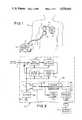
- FIG. 1is a perspective view of a battery powered implantable cardiac pacer including a battery consumption monitoring system constructed in accordance with the invention.
- FIG. 2is a functional block diagram showing the principal elements of the cardiac pacer of FIG. 1.
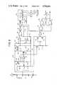
- FIG. 3is a simplified schematic diagram of the battery consumption monitor system.
- FIG. 4is a simplified schematic diagram of a portion of the battery usage monitoring system showing an alternative current sensing circuit for use in conjunction with series-connected batteries.
- FIG. 5is a simplified schematic diagram of a portion of the battery consumption monitoring system showing an alternative output circuit for use in conjunction with an external microprocessor.
- a battery-operated implantable cardiac pacer 10is shown implanted within a patient 11.
- the output of the paceris connected to the patient's heart 12 (shown in cross section) by means of a pacer lead 13, which may be conventional in construction and operation.
- the pacer 10is preferably formed as a unitary self-contained sealed device such that its operation is unaffected by exposure to body fluids.
- Operation of the pacercan be monitored by multiplextype monitor apparatus 14 external to the body and viewable by the patient or the attending physician.
- the monitoring apparatus 14includes a digital readout 15 on which, in accordance with the invention, an indication of consumed battery capacity is provided.
- Communication between apparatus 14 and pacer 10may be provided by a magnetic or radio-frequency pickup 16 positioned by the user on the chest of the patient in close proximity to the pacer. The pickup receives telemetry data from the pacer in a manner well known to the art, and the resulting electrical signal is conveyed to apparatus 14 through a flexible electrical cable 17.
- the life remaining in the battery contained within the implanted pacer 10can be determined at any time by positioning pickup 16 in communication with the pacer. Interrogation signals are then applied to the pacer, wherein conventional telemetering circuitry responds by providing an output indicative of the charge actually consumed by the pacer circuitry from the battery up to that point. Knowing this information, and the available current capacity of the battery, the user can readily determine the actual battery life remaining.
- the implanted cardiac pacer 10is seen to include in accordance with conventional practice a sense amplifier 20 which amplifies the R-wave conveyed to the pacer by pacer lead 13 and connector 21.
- amplifier 20has a bandpass characteristic which attenuates noise and other extraneous signals picked-up by the pacer lead, so that the detected R-wave may be more effectively amplified.
- the amplified sense signalis applied to an R-wave detector 22, which provides an output pulse upon the occurrence of an R-wave component in the sensed signal.
- the detector output pulseis applied to a pulse control logic circuit 23, which under appropriate circumstances produces an output control pulse.
- This control pulseis applied to an output circuit 24 wherein it causes the generation of a pacer output pulse of predetermined amplitude and duration.
- This output pulseis applied through an output capacitor 25 to pacer lead 13, which conveys the pulse to the heart.
- pulse control logic circuit 23causes output circuit 24 to produce a pacer output pulse only in the event that an R-wave resulting from natural heart activity is not detected within a selected time period.
- Operating power for the implanted pacer 10is obtained from a self-contained battery 29, which may be a conventional type intended for use in implanted pacemakers, such as the lithium type now widely used in such applications.
- the negative polarity output terminal of battery 29is connected to pacer ground, and in accordance with conventional practice is connected to an electrically conductive outer surface on the pacer to establish a ground reference for the pacer output pulses.
- the positive-polarity battery terminalis connected to the various circuits of the pacer and serves to supply unidirectional operating current for their operation.
- the unidirectional current developed by battery 29is applied to the pacer circuitry through a battery consumption monitor circuit 30 which includes a series-connected current-metering resistor 31. A voltage is produced across this resistor which is proportional to the current demand of the pacer circuitry. This voltage is applied to an amplifier 32.
- the amplified current-indicative signal at the output of amplifier 32is applied to a voltage controlled oscillator 33 which produces an output signal having a frequency dependent on the applied voltage level, and hence on the current demand of the pacer circuitry.
- This signalis applied to a counter 34, wherein a cumulative count is developed which is representative of the total energy consumed from the battery.
- This countmay be read out by means of conventional telemetry circuitry 35 which functions in conjunction with a pickup coil 36 in a manner well known to the art to convey the count in the counter to external apparatus, such as the previously described display apparatus.
- the multiplex circuit 35may also serve to vary the operating parameters of the pacer in response to command signals from external control apparatus, thus performing the dual functions of reading out parameters of the pacer for display to an operator, and of conveying commands from the operator to change the operating parameters of the pacer.
- An additional feature of the battery consumption monitor systemis the provision of an over-current alarm 37 which provides an alarm in the event that the current through sensing register 31 exceeds a predetermined maximum level.
- over-current alarm 37continuously compares the amplified sensing signal from the amplifier 32 against an internally provided reference corresponding to the current limit, and in the event of a comparison provides the alarm output signal.
- the alarmmay take the form of a variation in pacing rate, in which case the alarm output is connected to pulse control logic circuit 23.
- the over-current alarmmay take the form of an implanted device which vibrates to alert the patient. In either event, the patient is alerted to the over-current condition, and the probable malfunction of the pacer circuitry.
- the battery consumption monitor circuit 30is seen to comprise a differential amplifier 41 for comparing the voltage levels on either side of the current sensing resistor 31.
- the voltage level on the upline or battery side (at point A) of resistor 31is applied ro the non-inverting input of the comparator through a voltage divider network comprising a resistor 42, a potentiometer 43, and a resistor 44.
- a predetermined portion of the terminal A voltageis impressed on the non-inverting input.
- a predetermined portion of the downline voltage at resistor 31, (at point B)is applied to the inverting input through a second voltage divider comprising resistors 45, 46 and 47.
- the juncture of resistors 45 and 46is connected to ground through a capacitor 48 to provide filtering at the comparator input, and the inverting input of the comparator is connected to the juncture of resistors 46 and 47.
- the output of comparator 41is applied to the base electrode of an N-type transistor 50 and by a resistor 51 to the juncture of resistors 46 and 47. With this arrangement, an amplified output signal is developed at the output of comparator 41 having a voltage level dependent on the current drawn by the pacer from battery 29 through resistor 31.
- the variable voltage signal from comparator 41is converted to a variable current signal by N-type transistor 50, which has one principal electrode oonnected to ground through a resistor 52 and its other principal electrode connected to the supply line 53 through the principal electrodes of a P-type transistor 54.
- the current through the principal electrodes of transistor 50is proportional to the voltage level at the output of comparator 41, and hence to the current through sensing resistor 31. This current is mirrored by a pair of P-type transistors 54 and 55 connected back-to-back, with the principal electrode of transistor 50 being connected to the two control electrodes of the transistor pair.
- the principal electrodes of transistor 55are connected to supply line 53, and through a capacitor 56 to ground.
- the juncture of capacitor 56 and transistor 55is connected to the non-inverting input of a second comparator amplifier 57.
- the inverting terminal of comparator 57has a predetermined reference voltage applied to it by a voltage divider comprising a pair of resistors 58 and 59 connected between supply line 53 and ground.
- the output of comparator 57is applied through a NOR gate 60 and a pair of inverters 61 and 62 to the clock input of a 27-bit ripple counter 63.
- the output of inverter 61is also connected to the base electrode of a transistor 65 having principal electrodes connected across timing capacitor 56.
- the remaining input of NOR gate 60is connected by a capacitor 64 to inverter 61 and by a resistor 66 to ground.
- capacitor 56is charged from supply line 53 through transistor 55. Since the current level at transistor 55 is a function of the voltage output at comparator 41, and hence the current drawn through sensing resistor 31, the time required to charge capacitor 56 to a selected reference level is dependent on the current required by the pacer. The greater the required current, the more quickly capacitor 56 is charged.
- the reference level to which capacitor 56 is chargedis set by the voltage applied by resistors 58 and 59 to the inverting input of comparator 57. When this reference level is reached, an output is produced by comparator 57 which is applied through NOR gate 60 and inverter 61 to the control electrode of transistor 65. This conditions the transistor into saturation, causing capacitor 56 to be discharged. After capacitor 56 has discharged, an output is no longer produced by comparator 57. To prevent the capacitor 56 from immediately recharging capacitor 64 and resistor 66 provide a continuing signal for a short interval on OR gate 60. This causes an output pulse of predetermined fixed duration to be produced.
- Comparator amplifier 41 and its associated circuitryfunctions as a linear amplifier, and transistor 50, timing capacitor 56, comparator 57 and their associated circuitry functions as a voltage-controlled oscillator.
- the pulses produced at the output of inverter 62are applied to counter 63, causing that device to count upwards one count for each applied pulse.
- the gain of amplifier 41 and its related circuitsis such that counter 63 is advanced once for each milliampere hour drawn from the battery. As a result, at any given instant the count contained in counter 63 is equal to the number of milliampere-hours consumed from the battery.
- the multiplex circuit 35(FIG. 2) of the pacer, in practice it is only necessary to read out the five most significant digits.
- the multiplex circuitry required for this purposemay be entirely conventional in construction and operation.
- the additional function of monitoring for excessive current drainis accomplished by applying the amplified variable-voltage signal developed by comparator amplifier 41 to the base electrode of a P-type transistor 70.
- One principal electrode of this transistoris connected to supply line 53, and the other principal electrode is connected to ground through a resistor 71.
- the signal developed across resistor 71is applied to the base electrodes of a pair of P and N-type transistors 72 and 73 having principal electrodes connected in series between supply line 53 and ground.
- the juncture of these transistorsis connected through an inverter 74 to one input of a NOR gate 75.
- the other input of NOR gate 75is connected to the output of inverter 62.
- the amplified current-indicative variable-voltage signal from comparator 41causes transistor 70 to develop a current-indicative signal across resistor 71.
- This signalis applied to transistors 72 and 73, where it causes these devices to conduct when the current falls above the established threshold, and to cut-off when the current level falls below the threshold.
- the resulting alarm signaldeveloped at the juncture of the two transistors, is applied through inverter 74 to NOR gate 75.
- NOR gate 75is applied to one input of a NOR gate 80.
- the output of NOR gate 80is applied to one input of a NOR gate 81.
- the output of NOR gate 81is applied to the remaining input of NOR gate 80.
- the output of inverter 62is applied to the remaining input of inverter 81.
- NOR gates 80 and 81operate in a manner well known to the art to form a latch circuit which latches in the presence of an applied alarm signal from inverter 74.
- the latched alarm signalpresent at the output of NOR gate 81, is applied to an appropriate failure alarm such as a rate modification circuit in pulse control logic circuit 23 (FIG. 2), or a mechanical alarm device of conventional construction (not shown).
- an appropriate failure alarmsuch as a rate modification circuit in pulse control logic circuit 23 (FIG. 2), or a mechanical alarm device of conventional construction (not shown).
- the appropriate alarm deviceis actuated to alert the patient to a malfunction in the pacer, enabling corrective action to be taken to preclude premature battery failure.
- the battery consumption monitor circuit of the inventionmay be utilized in conjunction with a pacer powered by two batteries.
- the sensing resistor 31is located between two serially-connected batteries 82 and 83.
- the batteriesare selected to provide when connected in series the required operating voltage of the pacer.
- the upline (A) connection of resistor 31is applied through a resistor 84 to the non-inverting input of comparator amplifier 41.
- the downline (B) connection of resistor 31is applied through a filter network comprising the series combination of resistors 85 and 86 to the inverting input of comparator amplifier 41.
- a filter capacitor 87is connected between the juncture of the resistors 85 and 86 and resistor 81.
- the operating point of comparator amplifier 41is set by a unijunction transistor 90 connected in series with a resistor 91 between the inverting input of the comparator and the supply line 53 of the pacer.
- the voltage developed across sensing resistor 31is applied to the terminals of comparator amplifier 41 to produce at the output of the comparator an amplified signal having a voltage level dependent on pacer current drain.
- a change in current draincauses a proportional change in the charging current of capacitor 56 and consequently, a proportional change in the repetition rate, or frequency, at the output of inverter 62. Therefore, counter 63 is caused to accumulate a count representative of the cumulative current drain from the batteries.
- the monitor circuitmay be identical to that shown in FIG. 3.
- the size of the 27-bit ripple counter 63may be reduced by utilizing external storage and counting capability, such as may be found in an external microprocessor.
- the output of inverter 62may be alternatively applied to an eight-bit ripple counter 92 arranged to accumulate the pulses produced by the voltage controlled oscillator formed by transistors 50, 54, 55, comparator 57, NOR gate 60 and inverters 61 and 62.
- the most significant (Q 8 ) output of the counteris connected to the multiplex circuit, since the external counting capability requires only the overflow from the counter.
- the gain of comparator amplifier 41 and the associated circuitry of the voltage controlled oscillatormay be advantageously selected to enter a count into counter 63 (FIG. 3) following each 1 milliampere hour consumed from the battery. Assuming a typical current drain of 20.7 microamperes for the cardiac pacer, and a 2.0 ampere house battery capacity, a theoretical battery life of 11 years is indicated. For the average current drain, the voltage controlled oscillator will operate at a frequency of 0.5 hertz, or 1 pulse every 2 seconds. Since there are 31,536,000 seconds in one year, it follows that 15,768,000 clock pulses will be counted by the counter each
- the countermay be initially set to the theoretical maximum energy capacity of the battery, and then counted down with each increment of energy consumption to read out directly battery consumption remaining.
- the battery consumption monitoring circuithas been shown in conjunction with an implanted cardiac pacer, it will be appreciated that the circuit can be utilized with other types of devices intended to operate from a battery over a long time period, such as implantable pumps, telemetering devices, instrumentation, and the like.
Landscapes
- Health & Medical Sciences (AREA)
- Heart & Thoracic Surgery (AREA)
- Life Sciences & Earth Sciences (AREA)
- Biomedical Technology (AREA)
- Cardiology (AREA)
- Engineering & Computer Science (AREA)
- Biophysics (AREA)
- Nuclear Medicine, Radiotherapy & Molecular Imaging (AREA)
- Radiology & Medical Imaging (AREA)
- Animal Behavior & Ethology (AREA)
- General Health & Medical Sciences (AREA)
- Public Health (AREA)
- Veterinary Medicine (AREA)
- Electrotherapy Devices (AREA)
Abstract
Description
______________________________________ FIVE MOST TOTAL BCD READING SIGNIFICANT BITS YEAR COUNT AMP/HOURS 1 2 3 4 5 ______________________________________ 1 15,768,000 0.1 1 .0. .0. .0. .0. 2 31,536,000 0.3 1 1 .0. .0. .0. 3 47,304,000 0.5 1 .0. 1 .0. .0. 4 63,072,000 0.7 1 1 1 .0. .0. 5 78,840,000 0.9 1 .0. .0. 1 .0. 6 94,608,000 1.1 1 1 .0. 1 .0. 7 110,376,000 1.3 1 .0. 1 1 .0. 8 126,144,000 1.5 1 1 1 1 .0. 9 141,912,000 1.6 .0. .0. .0. .0. 1 10 157,680,000 1.8 .0. 1 .0. .0. 1 11 173,448,000 2.0 .0. .0. 1 .0. 1 ______________________________________
Claims (5)
Priority Applications (1)
| Application Number | Priority Date | Filing Date | Title |
|---|---|---|---|
| US06/710,531US4556061A (en) | 1982-08-18 | 1985-03-12 | Cardiac pacer with battery consumption monitor circuit |
Applications Claiming Priority (2)
| Application Number | Priority Date | Filing Date | Title |
|---|---|---|---|
| US40932982A | 1982-08-18 | 1982-08-18 | |
| US06/710,531US4556061A (en) | 1982-08-18 | 1985-03-12 | Cardiac pacer with battery consumption monitor circuit |
Related Parent Applications (1)
| Application Number | Title | Priority Date | Filing Date |
|---|---|---|---|
| US40932982AContinuation | 1982-08-18 | 1982-08-18 |
Publications (1)
| Publication Number | Publication Date |
|---|---|
| US4556061Atrue US4556061A (en) | 1985-12-03 |
Family
ID=27020606
Family Applications (1)
| Application Number | Title | Priority Date | Filing Date |
|---|---|---|---|
| US06/710,531Expired - LifetimeUS4556061A (en) | 1982-08-18 | 1985-03-12 | Cardiac pacer with battery consumption monitor circuit |
Country Status (1)
| Country | Link |
|---|---|
| US (1) | US4556061A (en) |
Cited By (94)
| Publication number | Priority date | Publication date | Assignee | Title |
|---|---|---|---|---|
| US4686990A (en)* | 1985-10-02 | 1987-08-18 | Siemens Aktiengesellschaft | Battery test circuit for a heart pacemaker |
| US4715381A (en)* | 1985-10-02 | 1987-12-29 | Siemens Aktiengesellschaft | Battery test circuit for a heart pacemaker |
| EP0360551A3 (en)* | 1988-09-20 | 1992-06-10 | Medtronic, Inc. | Method and apparatus for measuring the lead current in a pacemaker |
| US5128552A (en)* | 1989-09-29 | 1992-07-07 | Buddy Systems, Inc. | System and method for power supply preservation in a personal health monitor |
| US5237991A (en)* | 1991-11-19 | 1993-08-24 | Cyberonics, Inc. | Implantable medical device with dummy load for pre-implant testing in sterile package and facilitating electrical lead connection |
| EP0647455A1 (en)* | 1993-10-06 | 1995-04-12 | Vitatron Medical B.V. | Cardiac pacing system with improved end-of-life detector |
| US5522856A (en)* | 1994-09-20 | 1996-06-04 | Vitatron Medical, B.V. | Pacemaker with improved shelf storage capacity |
| US5562714A (en)* | 1995-02-03 | 1996-10-08 | Medtronic, Inc. | Magnetic field strength regulator for implant |
| US5591217A (en)* | 1995-01-04 | 1997-01-07 | Plexus, Inc. | Implantable stimulator with replenishable, high value capacitive power source and method therefor |
| US5620474A (en)* | 1995-04-24 | 1997-04-15 | Vitatron Medical, B.V. | System and method for determining indicated pacemaker replacement time based upon battery impedance measurement |
| US6108579A (en)* | 1996-04-15 | 2000-08-22 | Pacesetter, Inc. | Battery monitoring apparatus and method for programmers of cardiac stimulating devices |
| US6166524A (en)* | 2000-03-09 | 2000-12-26 | Wilson Greatbatch Ltd. | Alternate fuel gauge for an alkali metal electrochemical cell |
| US6320969B1 (en)* | 1989-09-29 | 2001-11-20 | Etymotic Research, Inc. | Hearing aid with audible alarm |
| US6377850B1 (en) | 2000-03-09 | 2002-04-23 | Wilson Greatbatch Ltd. | Fuel gauge for an alkali metal electrochemical cell |
| US6400988B1 (en) | 2000-02-18 | 2002-06-04 | Pacesetter, Inc. | Implantable cardiac device having precision RRT indication |
| US20020161328A1 (en)* | 2001-03-16 | 2002-10-31 | Medtronic, Inc. | Implantable therapeutic substance infusion device with active longevity projection |
| US6584355B2 (en) | 2001-04-10 | 2003-06-24 | Cardiac Pacemakers, Inc. | System and method for measuring battery current |
| US20030181953A1 (en)* | 2002-03-19 | 2003-09-25 | Dropps Frank R. | Current monitor for an implantable medical device |
| US20040024426A1 (en)* | 1997-09-15 | 2004-02-05 | Cardiac Pacemakers, Inc. | Method for monitoring end of life for battery |
| US20040073264A1 (en)* | 1997-09-15 | 2004-04-15 | Cardiac Pacemakers, Inc. | Method for monitoring end of life for battery |
| NL1022496C2 (en)* | 2003-01-27 | 2004-07-28 | Sensite Solutions B V | Determining available capacity of power source for transmitter in tracing and telemetry system, based on total number data packets that can be and have been sent |
| US6820019B1 (en)* | 1999-07-31 | 2004-11-16 | Medtronic, Inc. | Device and method for determining and communicating the remaining life of a battery in an implantable neurological tissue stimulating device |
| US20050007073A1 (en)* | 2003-07-11 | 2005-01-13 | James Kristofer J. | Indicator of remaining energy in storage cell of implantable medical device |
| US20050088145A1 (en)* | 2003-10-23 | 2005-04-28 | Robert Loch | Battery charge indicator such as for an implantable medical device |
| US20050096514A1 (en)* | 2003-11-01 | 2005-05-05 | Medtronic, Inc. | Gastric activity notification |
| US6897788B2 (en) | 2000-04-18 | 2005-05-24 | Motorola, Inc. | Wireless system protocol for telemetry monitoring |
| US6901293B2 (en) | 2003-04-07 | 2005-05-31 | Medtronic, Inc. | System and method for monitoring power source longevity of an implantable medical device |
| US20050177206A1 (en)* | 2003-02-21 | 2005-08-11 | North Richard B. | Implantable neurostimulator programming with battery longevity indication |
| US6987965B2 (en) | 2000-04-18 | 2006-01-17 | Motorola, Inc. | Programmable wireless electrode system for medical monitoring |
| US20060025829A1 (en)* | 2004-07-28 | 2006-02-02 | Armstrong Randolph K | Power supply monitoring for an implantable device |
| US20070055308A1 (en)* | 2005-09-06 | 2007-03-08 | Haller Matthew I | Ultracapacitor powered implantable pulse generator with dedicated power supply |
| WO2007026712A1 (en) | 2005-08-29 | 2007-03-08 | Olympus Medical Systems Corp. | In-examiner information acquisition system |
| US7194308B2 (en) | 2003-11-12 | 2007-03-20 | Cardiac Pacemakers, Inc. | System and method for monitoring or reporting battery status of implantable medical device |
| US7197357B2 (en) | 2001-07-17 | 2007-03-27 | Life Sync Corporation | Wireless ECG system |
| US7215991B2 (en) | 1993-09-04 | 2007-05-08 | Motorola, Inc. | Wireless medical diagnosis and monitoring equipment |
| US7215999B1 (en)* | 2003-08-06 | 2007-05-08 | Pacesetter, Inc. | Battery charge indicator for implantable pacemakers and defibrillators |
| US20070179547A1 (en)* | 2006-01-27 | 2007-08-02 | Cyberonics, Inc. | Power supply monitoring for an implantable device |
| US7272428B2 (en) | 2000-07-18 | 2007-09-18 | Motorola, Inc. | Wireless electrocardiograph system and method |
| US20070260116A1 (en)* | 2005-08-29 | 2007-11-08 | Olympus Corporation And Olympus Medical Systems Corp. | Body-insertable apparatus and receiving apparatus for recognizing remaining power amount |
| US20080097544A1 (en)* | 2006-10-20 | 2008-04-24 | Rajesh Krishan Gandhi | Dynamic battery management in an implantable device |
| US20080177345A1 (en)* | 2007-01-18 | 2008-07-24 | Schmidt Craig L | Methods for estimating remaining battery service life in an implantable medical device |
| US20080183097A1 (en)* | 2007-01-25 | 2008-07-31 | Leyde Kent W | Methods and Systems for Measuring a Subject's Susceptibility to a Seizure |
| US7469161B1 (en)* | 2004-12-16 | 2008-12-23 | Cardiac Pacemakers, Inc. | Systems and methods for monitoring and managing power consumption of an implantable medical device |
| US20080316198A1 (en)* | 2004-09-15 | 2008-12-25 | Sharp Kabushiki Kaisha | Display Device, Viewing Angel Control Device, and Electronic Apparatus |
| US20090018607A1 (en)* | 2007-03-15 | 2009-01-15 | Cvrx, Inc. | Methods and devices for controlling battery life in an implantable pulse generator |
| US20090099625A1 (en)* | 2007-07-20 | 2009-04-16 | Tom Crowley | Elective service indicator based on pulse count for implantable device |
| US20090182517A1 (en)* | 2007-12-13 | 2009-07-16 | Cardiac Pacemakers, Inc. | Abnormal battery depletion detection in an implantable device |
| US20090254356A1 (en)* | 2008-04-03 | 2009-10-08 | Medtronic, Inc. | Battery longevity monitoring |
| US7606618B1 (en) | 2006-04-07 | 2009-10-20 | Pacesetter, Inc. | Implantable medical device with notification system |
| US20090273349A1 (en)* | 2008-04-30 | 2009-11-05 | Medtronic, Inc. | System and method for monitoring a power source of an implantable medical device |
| US7617001B2 (en) | 2000-10-16 | 2009-11-10 | Remon Medical Technologies, Ltd | Systems and method for communicating with implantable devices |
| US20090312809A1 (en)* | 2008-06-17 | 2009-12-17 | Gandhi Rajesh K | Battery depth of discharge in an implantable device |
| US7650185B2 (en) | 2006-04-25 | 2010-01-19 | Cardiac Pacemakers, Inc. | System and method for walking an implantable medical device from a sleep state |
| US20100076254A1 (en)* | 2006-06-05 | 2010-03-25 | Ams Research Corporation | Electrical muscle stimulation to treat fecal incontinence and/or pelvic prolapse |
| US20100114510A1 (en)* | 2007-03-30 | 2010-05-06 | Ams Research Corporation | Methods and apparatus for monitoring battery charge depletion |
| US7729758B2 (en) | 2005-11-30 | 2010-06-01 | Boston Scientific Neuromodulation Corporation | Magnetically coupled microstimulators |
| US20100145176A1 (en)* | 2008-12-04 | 2010-06-10 | Himes David M | Universal Electrode Array for Monitoring Brain Activity |
| US20100168604A1 (en)* | 2008-12-29 | 2010-07-01 | Javier Ramon Echauz | Processing for Multi-Channel Signals |
| AU2008202335B2 (en)* | 2005-08-29 | 2010-07-29 | Olympus Corporation | Intra-subject information acquiring system |
| US20100302270A1 (en)* | 2009-06-02 | 2010-12-02 | Echauz Javier Ramon | Processing for Multi-Channel Signals |
| US7930031B2 (en) | 2000-10-16 | 2011-04-19 | Remon Medical Technologies, Ltd. | Acoustically powered implantable stimulating device |
| US20110106213A1 (en)* | 2009-10-29 | 2011-05-05 | Medtronic, Inc. | User interface for optimizing energy management in a neurostimulation system |
| USRE42378E1 (en) | 2000-10-16 | 2011-05-17 | Remon Medical Technologies, Ltd. | Implantable pressure sensors and methods for making and using them |
| US20110201944A1 (en)* | 2010-02-12 | 2011-08-18 | Higgins Jason A | Neurological monitoring and alerts |
| US8078278B2 (en) | 2006-01-10 | 2011-12-13 | Remon Medical Technologies Ltd. | Body attachable unit in wireless communication with implantable devices |
| US8255041B2 (en) | 2001-07-17 | 2012-08-28 | Lifesync Corporation | Wireless ECG system |
| US8295934B2 (en) | 2006-11-14 | 2012-10-23 | Neurovista Corporation | Systems and methods of reducing artifact in neurological stimulation systems |
| US8340776B2 (en) | 2007-03-26 | 2012-12-25 | Cardiac Pacemakers, Inc. | Biased acoustic switch for implantable medical device |
| US8380312B2 (en) | 2009-12-31 | 2013-02-19 | Ams Research Corporation | Multi-zone stimulation implant system and method |
| US8452395B2 (en) | 2010-07-06 | 2013-05-28 | Medtronic, Inc. | Battery longevity estimator that accounts for episodes of high current drain |
| US8543199B2 (en) | 2007-03-21 | 2013-09-24 | Cyberonics, Inc. | Implantable systems and methods for identifying a contra-ictal condition in a subject |
| US8577459B2 (en) | 2011-01-28 | 2013-11-05 | Cyberonics, Inc. | System and method for estimating battery capacity |
| US8588933B2 (en) | 2009-01-09 | 2013-11-19 | Cyberonics, Inc. | Medical lead termination sleeve for implantable medical devices |
| US8593107B2 (en) | 2008-10-27 | 2013-11-26 | Cardiac Pacemakers, Inc. | Methods and systems for recharging an implanted device by delivering a section of a charging device adjacent the implanted device within a body |
| US8761884B2 (en) | 2011-04-14 | 2014-06-24 | Cyberonics, Inc. | Device longevity prediction for a device having variable energy consumption |
| US8761885B2 (en) | 2011-04-29 | 2014-06-24 | Cyberonics, Inc. | Battery life estimation based on voltage depletion rate |
| US8781597B2 (en) | 1998-08-05 | 2014-07-15 | Cyberonics, Inc. | Systems for monitoring a patient's neurological disease state |
| US8798761B2 (en) | 2008-06-27 | 2014-08-05 | Cardiac Pacemakers, Inc. | Systems and methods of monitoring the acoustic coupling of medical devices |
| US8868172B2 (en) | 2005-12-28 | 2014-10-21 | Cyberonics, Inc. | Methods and systems for recommending an appropriate action to a patient for managing epilepsy and other neurological disorders |
| US8874229B2 (en) | 2010-04-28 | 2014-10-28 | Cyberonics, Inc. | Delivering scheduled and unscheduled therapy without detriment to battery life or accuracy of longevity predictions |
| US8942935B2 (en) | 2010-06-14 | 2015-01-27 | Medtronic, Inc. | Charge level measurement |
| US20150115900A1 (en)* | 2013-10-30 | 2015-04-30 | Cameron Health, Inc. | Selectable upper voltage range monitoring circuit |
| US9113801B2 (en) | 1998-08-05 | 2015-08-25 | Cyberonics, Inc. | Methods and systems for continuous EEG monitoring |
| US9259591B2 (en) | 2007-12-28 | 2016-02-16 | Cyberonics, Inc. | Housing for an implantable medical device |
| US9345883B2 (en) | 2014-02-14 | 2016-05-24 | Boston Scientific Neuromodulation Corporation | Rechargeable-battery implantable medical device having a primary battery active during a rechargeable-battery undervoltage condition |
| US9375573B2 (en) | 1998-08-05 | 2016-06-28 | Cyberonics, Inc. | Systems and methods for monitoring a patient's neurological disease state |
| US9421373B2 (en) | 1998-08-05 | 2016-08-23 | Cyberonics, Inc. | Apparatus and method for closed-loop intracranial stimulation for optimal control of neurological disease |
| US9469437B2 (en) | 2013-01-18 | 2016-10-18 | Cyberonics, Inc. | Radiofrequency shielded container |
| US9480845B2 (en) | 2006-06-23 | 2016-11-01 | Cyberonics, Inc. | Nerve stimulation device with a wearable loop antenna |
| US9694192B2 (en) | 2013-10-04 | 2017-07-04 | Boston Scientific Neuromodulation Corporation | Implantable medical device with a primary and rechargeable battery |
| US9731112B2 (en) | 2011-09-08 | 2017-08-15 | Paul J. Gindele | Implantable electrode assembly |
| US9788744B2 (en) | 2007-07-27 | 2017-10-17 | Cyberonics, Inc. | Systems for monitoring brain activity and patient advisory device |
| US9898656B2 (en) | 2007-01-25 | 2018-02-20 | Cyberonics, Inc. | Systems and methods for identifying a contra-ictal condition in a subject |
| US10159847B2 (en) | 2015-05-20 | 2018-12-25 | Medtronic, Inc. | Implantable medical devices with active component monitoring |
Citations (8)
| Publication number | Priority date | Publication date | Assignee | Title |
|---|---|---|---|---|
| US3742938A (en)* | 1971-01-04 | 1973-07-03 | T Stern | Cardiac pacer and heart pulse monitor |
| US3832994A (en)* | 1972-04-21 | 1974-09-03 | Mediscience Corp | Cardiac monitor |
| US3841336A (en)* | 1973-12-14 | 1974-10-15 | American Optical Corp | Pacer battery failure detection circuit |
| US3986498A (en)* | 1975-09-08 | 1976-10-19 | Videodetics Corporation | Remote ECG monitoring system |
| US4151454A (en)* | 1976-09-20 | 1979-04-24 | Kabushiki Kaisha Aichi Denkikosakusho | Remaining capacity detector of a battery |
| US4194146A (en)* | 1976-08-11 | 1980-03-18 | Saft-Societe Des Accumulateurs Fixes Et De Traction | Device for controlling the charging and discharging of a storage battery |
| US4321541A (en)* | 1978-12-04 | 1982-03-23 | Tokyo Shibaura Denki Kabushiki Kaisha | Cell capacity detector |
| US4460870A (en)* | 1981-07-23 | 1984-07-17 | Curtis Instruments, Inc. | Quiescent voltage sampling battery state of charge meter |
- 1985
- 1985-03-12USUS06/710,531patent/US4556061A/ennot_activeExpired - Lifetime
Patent Citations (8)
| Publication number | Priority date | Publication date | Assignee | Title |
|---|---|---|---|---|
| US3742938A (en)* | 1971-01-04 | 1973-07-03 | T Stern | Cardiac pacer and heart pulse monitor |
| US3832994A (en)* | 1972-04-21 | 1974-09-03 | Mediscience Corp | Cardiac monitor |
| US3841336A (en)* | 1973-12-14 | 1974-10-15 | American Optical Corp | Pacer battery failure detection circuit |
| US3986498A (en)* | 1975-09-08 | 1976-10-19 | Videodetics Corporation | Remote ECG monitoring system |
| US4194146A (en)* | 1976-08-11 | 1980-03-18 | Saft-Societe Des Accumulateurs Fixes Et De Traction | Device for controlling the charging and discharging of a storage battery |
| US4151454A (en)* | 1976-09-20 | 1979-04-24 | Kabushiki Kaisha Aichi Denkikosakusho | Remaining capacity detector of a battery |
| US4321541A (en)* | 1978-12-04 | 1982-03-23 | Tokyo Shibaura Denki Kabushiki Kaisha | Cell capacity detector |
| US4460870A (en)* | 1981-07-23 | 1984-07-17 | Curtis Instruments, Inc. | Quiescent voltage sampling battery state of charge meter |
Cited By (163)
| Publication number | Priority date | Publication date | Assignee | Title |
|---|---|---|---|---|
| US4686990A (en)* | 1985-10-02 | 1987-08-18 | Siemens Aktiengesellschaft | Battery test circuit for a heart pacemaker |
| US4715381A (en)* | 1985-10-02 | 1987-12-29 | Siemens Aktiengesellschaft | Battery test circuit for a heart pacemaker |
| EP0360551A3 (en)* | 1988-09-20 | 1992-06-10 | Medtronic, Inc. | Method and apparatus for measuring the lead current in a pacemaker |
| US5128552A (en)* | 1989-09-29 | 1992-07-07 | Buddy Systems, Inc. | System and method for power supply preservation in a personal health monitor |
| US6320969B1 (en)* | 1989-09-29 | 2001-11-20 | Etymotic Research, Inc. | Hearing aid with audible alarm |
| US5237991A (en)* | 1991-11-19 | 1993-08-24 | Cyberonics, Inc. | Implantable medical device with dummy load for pre-implant testing in sterile package and facilitating electrical lead connection |
| US8771184B2 (en) | 1993-09-04 | 2014-07-08 | Body Science Llc | Wireless medical diagnosis and monitoring equipment |
| US7215991B2 (en) | 1993-09-04 | 2007-05-08 | Motorola, Inc. | Wireless medical diagnosis and monitoring equipment |
| EP0647455A1 (en)* | 1993-10-06 | 1995-04-12 | Vitatron Medical B.V. | Cardiac pacing system with improved end-of-life detector |
| US5458624A (en)* | 1993-10-06 | 1995-10-17 | Vitatron Medical, B.V. | Cardiac pacing system with improved end-of-life detector |
| US5522856A (en)* | 1994-09-20 | 1996-06-04 | Vitatron Medical, B.V. | Pacemaker with improved shelf storage capacity |
| US5807397A (en)* | 1995-01-04 | 1998-09-15 | Plexus, Inc. | Implantable stimulator with replenishable, high value capacitive power source and method therefor |
| US5769877A (en)* | 1995-01-04 | 1998-06-23 | Plexus, Inc. | High value capacitive, replenishable power source |
| US5591217A (en)* | 1995-01-04 | 1997-01-07 | Plexus, Inc. | Implantable stimulator with replenishable, high value capacitive power source and method therefor |
| US5562714A (en)* | 1995-02-03 | 1996-10-08 | Medtronic, Inc. | Magnetic field strength regulator for implant |
| US5620474A (en)* | 1995-04-24 | 1997-04-15 | Vitatron Medical, B.V. | System and method for determining indicated pacemaker replacement time based upon battery impedance measurement |
| US6108579A (en)* | 1996-04-15 | 2000-08-22 | Pacesetter, Inc. | Battery monitoring apparatus and method for programmers of cardiac stimulating devices |
| US20040073264A1 (en)* | 1997-09-15 | 2004-04-15 | Cardiac Pacemakers, Inc. | Method for monitoring end of life for battery |
| US7251527B2 (en) | 1997-09-15 | 2007-07-31 | Cardiac Pacemakers, Inc. | Method for monitoring end of life for battery |
| US7515962B2 (en) | 1997-09-15 | 2009-04-07 | Cardiac Pacemakers, Inc. | Method for monitoring end of life for battery |
| US7580749B2 (en) | 1997-09-15 | 2009-08-25 | Cardiac Pacemakers, Inc. | Method for monitoring end of life for battery |
| US20070265672A1 (en)* | 1997-09-15 | 2007-11-15 | Cardiac Pacemakers, Inc. | Method for monitoring end of life for battery |
| US20040024426A1 (en)* | 1997-09-15 | 2004-02-05 | Cardiac Pacemakers, Inc. | Method for monitoring end of life for battery |
| US9375573B2 (en) | 1998-08-05 | 2016-06-28 | Cyberonics, Inc. | Systems and methods for monitoring a patient's neurological disease state |
| US9320900B2 (en) | 1998-08-05 | 2016-04-26 | Cyberonics, Inc. | Methods and systems for determining subject-specific parameters for a neuromodulation therapy |
| US9113801B2 (en) | 1998-08-05 | 2015-08-25 | Cyberonics, Inc. | Methods and systems for continuous EEG monitoring |
| US9421373B2 (en) | 1998-08-05 | 2016-08-23 | Cyberonics, Inc. | Apparatus and method for closed-loop intracranial stimulation for optimal control of neurological disease |
| US8781597B2 (en) | 1998-08-05 | 2014-07-15 | Cyberonics, Inc. | Systems for monitoring a patient's neurological disease state |
| US6820019B1 (en)* | 1999-07-31 | 2004-11-16 | Medtronic, Inc. | Device and method for determining and communicating the remaining life of a battery in an implantable neurological tissue stimulating device |
| US6400988B1 (en) | 2000-02-18 | 2002-06-04 | Pacesetter, Inc. | Implantable cardiac device having precision RRT indication |
| US6166524A (en)* | 2000-03-09 | 2000-12-26 | Wilson Greatbatch Ltd. | Alternate fuel gauge for an alkali metal electrochemical cell |
| US6377850B1 (en) | 2000-03-09 | 2002-04-23 | Wilson Greatbatch Ltd. | Fuel gauge for an alkali metal electrochemical cell |
| US7171166B2 (en) | 2000-04-18 | 2007-01-30 | Motorola Inc. | Programmable wireless electrode system for medical monitoring |
| US6897788B2 (en) | 2000-04-18 | 2005-05-24 | Motorola, Inc. | Wireless system protocol for telemetry monitoring |
| US6987965B2 (en) | 2000-04-18 | 2006-01-17 | Motorola, Inc. | Programmable wireless electrode system for medical monitoring |
| US7272428B2 (en) | 2000-07-18 | 2007-09-18 | Motorola, Inc. | Wireless electrocardiograph system and method |
| US7930031B2 (en) | 2000-10-16 | 2011-04-19 | Remon Medical Technologies, Ltd. | Acoustically powered implantable stimulating device |
| US7756587B2 (en) | 2000-10-16 | 2010-07-13 | Cardiac Pacemakers, Inc. | Systems and methods for communicating with implantable devices |
| US7617001B2 (en) | 2000-10-16 | 2009-11-10 | Remon Medical Technologies, Ltd | Systems and method for communicating with implantable devices |
| US8934972B2 (en) | 2000-10-16 | 2015-01-13 | Remon Medical Technologies, Ltd. | Acoustically powered implantable stimulating device |
| US8577460B2 (en) | 2000-10-16 | 2013-11-05 | Remon Medical Technologies, Ltd | Acoustically powered implantable stimulating device |
| USRE42378E1 (en) | 2000-10-16 | 2011-05-17 | Remon Medical Technologies, Ltd. | Implantable pressure sensors and methods for making and using them |
| US7001359B2 (en) | 2001-03-16 | 2006-02-21 | Medtronic, Inc. | Implantable therapeutic substance infusion device with active longevity projection |
| US20020161328A1 (en)* | 2001-03-16 | 2002-10-31 | Medtronic, Inc. | Implantable therapeutic substance infusion device with active longevity projection |
| US6885894B2 (en) | 2001-04-10 | 2005-04-26 | Cardiac Pacemakers, Inc. | System and method for measuring battery current |
| US7191005B2 (en) | 2001-04-10 | 2007-03-13 | Cardiac Pacemakers, Inc. | System and method for measuring battery current |
| US20030176897A1 (en)* | 2001-04-10 | 2003-09-18 | Cardiac Pacemakers, Inc. | System and method for measuring battery current |
| US20050143782A1 (en)* | 2001-04-10 | 2005-06-30 | Cardiac Pacemakers, Inc. | System and method for measuring battery current |
| US6584355B2 (en) | 2001-04-10 | 2003-06-24 | Cardiac Pacemakers, Inc. | System and method for measuring battery current |
| US8255041B2 (en) | 2001-07-17 | 2012-08-28 | Lifesync Corporation | Wireless ECG system |
| US7197357B2 (en) | 2001-07-17 | 2007-03-27 | Life Sync Corporation | Wireless ECG system |
| US20030181953A1 (en)* | 2002-03-19 | 2003-09-25 | Dropps Frank R. | Current monitor for an implantable medical device |
| US6898463B2 (en) | 2002-03-19 | 2005-05-24 | Medtronic, Inc. | Current monitor for an implantable medical device |
| WO2003080177A1 (en)* | 2002-03-19 | 2003-10-02 | Medtronic, Inc. | Current monitor for an implantable medical device |
| NL1022496C2 (en)* | 2003-01-27 | 2004-07-28 | Sensite Solutions B V | Determining available capacity of power source for transmitter in tracing and telemetry system, based on total number data packets that can be and have been sent |
| US20050177206A1 (en)* | 2003-02-21 | 2005-08-11 | North Richard B. | Implantable neurostimulator programming with battery longevity indication |
| US7142923B2 (en) | 2003-02-21 | 2006-11-28 | Medtronic, Inc. | Implantable neurostimulator programming with battery longevity indication |
| US20090210034A1 (en)* | 2003-04-07 | 2009-08-20 | Medtronic, Inc. | System and Method for Monitoring Power Source Longevity of an Implantable Medical Device |
| US8417338B2 (en) | 2003-04-07 | 2013-04-09 | Medtronic, Inc. | System and method for monitoring power source longevity of an implantable medical device |
| US8131367B2 (en) | 2003-04-07 | 2012-03-06 | Medtronic, Inc. | System and method for monitoring power source longevity of an implantable medical device |
| US6901293B2 (en) | 2003-04-07 | 2005-05-31 | Medtronic, Inc. | System and method for monitoring power source longevity of an implantable medical device |
| US7542801B2 (en) | 2003-04-07 | 2009-06-02 | Medtronic, Inc. | System and method for monitoring power source longevity of an implantable medical device |
| US20050007073A1 (en)* | 2003-07-11 | 2005-01-13 | James Kristofer J. | Indicator of remaining energy in storage cell of implantable medical device |
| US7239146B2 (en)* | 2003-07-11 | 2007-07-03 | Cardiac Pacemakers, Inc. | Indicator of remaining energy in storage cell of implantable medical device |
| US7215999B1 (en)* | 2003-08-06 | 2007-05-08 | Pacesetter, Inc. | Battery charge indicator for implantable pacemakers and defibrillators |
| US6940255B2 (en) | 2003-10-23 | 2005-09-06 | Cardiac Pacemakers, Inc. | Battery charge indicator such as for an implantable medical device |
| US20050088145A1 (en)* | 2003-10-23 | 2005-04-28 | Robert Loch | Battery charge indicator such as for an implantable medical device |
| US20050096514A1 (en)* | 2003-11-01 | 2005-05-05 | Medtronic, Inc. | Gastric activity notification |
| US7194308B2 (en) | 2003-11-12 | 2007-03-20 | Cardiac Pacemakers, Inc. | System and method for monitoring or reporting battery status of implantable medical device |
| US20060025829A1 (en)* | 2004-07-28 | 2006-02-02 | Armstrong Randolph K | Power supply monitoring for an implantable device |
| US20060025828A1 (en)* | 2004-07-28 | 2006-02-02 | Armstrong Randolph K | Impedance measurement for an implantable device |
| US7751891B2 (en) | 2004-07-28 | 2010-07-06 | Cyberonics, Inc. | Power supply monitoring for an implantable device |
| US20080316198A1 (en)* | 2004-09-15 | 2008-12-25 | Sharp Kabushiki Kaisha | Display Device, Viewing Angel Control Device, and Electronic Apparatus |
| US7469161B1 (en)* | 2004-12-16 | 2008-12-23 | Cardiac Pacemakers, Inc. | Systems and methods for monitoring and managing power consumption of an implantable medical device |
| US7945327B2 (en) | 2004-12-16 | 2011-05-17 | Cardiac Pacemakers, Inc. | Systems and methods for monitoring and managing power consumption of an implantable medical device |
| US20090069861A1 (en)* | 2004-12-16 | 2009-03-12 | Raj Gandhi | Systems and methods for monitoring and managing power consumption of an implantable medical device |
| CN101347322B (en)* | 2005-08-29 | 2012-07-04 | 奥林巴斯医疗株式会社 | In-examiner information acquisition system |
| EP1977683A3 (en)* | 2005-08-29 | 2009-03-18 | Olympus Medical Systems Corp. | Intra-subject information acquiring system |
| EP1920703A4 (en)* | 2005-08-29 | 2009-03-18 | Olympus Medical Systems Corp | SYSTEM FOR ACQUIRING INFORMATION FROM A PERSON EXAMINED |
| AU2006285873B2 (en)* | 2005-08-29 | 2010-05-13 | Olympus Corporation | In-examiner information acquisition system |
| EP1977683A2 (en) | 2005-08-29 | 2008-10-08 | Olympus Medical Systems Corp. | Intra-subject information acquiring system |
| AU2006285873B9 (en)* | 2005-08-29 | 2010-07-01 | Olympus Corporation | In-examiner information acquisition system |
| WO2007026712A1 (en) | 2005-08-29 | 2007-03-08 | Olympus Medical Systems Corp. | In-examiner information acquisition system |
| US20070260116A1 (en)* | 2005-08-29 | 2007-11-08 | Olympus Corporation And Olympus Medical Systems Corp. | Body-insertable apparatus and receiving apparatus for recognizing remaining power amount |
| CN101237809B (en)* | 2005-08-29 | 2010-12-08 | 奥林巴斯医疗株式会社 | In-vivo information acquisition system |
| AU2008202335B2 (en)* | 2005-08-29 | 2010-07-29 | Olympus Corporation | Intra-subject information acquiring system |
| US8175717B2 (en) | 2005-09-06 | 2012-05-08 | Boston Scientific Neuromodulation Corporation | Ultracapacitor powered implantable pulse generator with dedicated power supply |
| US20070055308A1 (en)* | 2005-09-06 | 2007-03-08 | Haller Matthew I | Ultracapacitor powered implantable pulse generator with dedicated power supply |
| US7729758B2 (en) | 2005-11-30 | 2010-06-01 | Boston Scientific Neuromodulation Corporation | Magnetically coupled microstimulators |
| US8868172B2 (en) | 2005-12-28 | 2014-10-21 | Cyberonics, Inc. | Methods and systems for recommending an appropriate action to a patient for managing epilepsy and other neurological disorders |
| US8078278B2 (en) | 2006-01-10 | 2011-12-13 | Remon Medical Technologies Ltd. | Body attachable unit in wireless communication with implantable devices |
| US7769455B2 (en) | 2006-01-27 | 2010-08-03 | Cyberonics, Inc. | Power supply monitoring for an implantable device |
| US20100268495A1 (en)* | 2006-01-27 | 2010-10-21 | Cyberonics, Inc. | Power supply monitoring for an implantable device |
| US8560070B2 (en) | 2006-01-27 | 2013-10-15 | Cyberonics, Inc. | Power supply monitoring for an implantable device |
| US20100198313A1 (en)* | 2006-01-27 | 2010-08-05 | Cyberonics, Inc. | Power supply monitoring for an implantable device |
| US8565881B2 (en) | 2006-01-27 | 2013-10-22 | Cyberonics, Inc. | Power supply monitoring for an implantable device |
| US20070179547A1 (en)* | 2006-01-27 | 2007-08-02 | Cyberonics, Inc. | Power supply monitoring for an implantable device |
| US7606618B1 (en) | 2006-04-07 | 2009-10-20 | Pacesetter, Inc. | Implantable medical device with notification system |
| US7650185B2 (en) | 2006-04-25 | 2010-01-19 | Cardiac Pacemakers, Inc. | System and method for walking an implantable medical device from a sleep state |
| US20100076254A1 (en)* | 2006-06-05 | 2010-03-25 | Ams Research Corporation | Electrical muscle stimulation to treat fecal incontinence and/or pelvic prolapse |
| US9480845B2 (en) | 2006-06-23 | 2016-11-01 | Cyberonics, Inc. | Nerve stimulation device with a wearable loop antenna |
| US20080097544A1 (en)* | 2006-10-20 | 2008-04-24 | Rajesh Krishan Gandhi | Dynamic battery management in an implantable device |
| US8718771B2 (en) | 2006-10-20 | 2014-05-06 | Cardiac Pacemakers, Inc. | Dynamic battery management in an implantable device |
| US8055343B2 (en) | 2006-10-20 | 2011-11-08 | Cardiac Pacemakers, Inc. | Dynamic battery management in an implantable device |
| US8295934B2 (en) | 2006-11-14 | 2012-10-23 | Neurovista Corporation | Systems and methods of reducing artifact in neurological stimulation systems |
| US8855775B2 (en) | 2006-11-14 | 2014-10-07 | Cyberonics, Inc. | Systems and methods of reducing artifact in neurological stimulation systems |
| US20080177345A1 (en)* | 2007-01-18 | 2008-07-24 | Schmidt Craig L | Methods for estimating remaining battery service life in an implantable medical device |
| US20110213222A1 (en)* | 2007-01-25 | 2011-09-01 | Leyde Kent W | Communication Error Alerting in an Epilepsy Monitoring System |
| US9898656B2 (en) | 2007-01-25 | 2018-02-20 | Cyberonics, Inc. | Systems and methods for identifying a contra-ictal condition in a subject |
| US20080183097A1 (en)* | 2007-01-25 | 2008-07-31 | Leyde Kent W | Methods and Systems for Measuring a Subject's Susceptibility to a Seizure |
| US9622675B2 (en) | 2007-01-25 | 2017-04-18 | Cyberonics, Inc. | Communication error alerting in an epilepsy monitoring system |
| US20090018607A1 (en)* | 2007-03-15 | 2009-01-15 | Cvrx, Inc. | Methods and devices for controlling battery life in an implantable pulse generator |
| US8150521B2 (en) | 2007-03-15 | 2012-04-03 | Cvrx, Inc. | Methods and devices for controlling battery life in an implantable pulse generator |
| US9445730B2 (en) | 2007-03-21 | 2016-09-20 | Cyberonics, Inc. | Implantable systems and methods for identifying a contra-ictal condition in a subject |
| US8543199B2 (en) | 2007-03-21 | 2013-09-24 | Cyberonics, Inc. | Implantable systems and methods for identifying a contra-ictal condition in a subject |
| US8340776B2 (en) | 2007-03-26 | 2012-12-25 | Cardiac Pacemakers, Inc. | Biased acoustic switch for implantable medical device |
| US8200444B2 (en) | 2007-03-30 | 2012-06-12 | Ams Research Corporation | Methods and apparatus for monitoring battery charge depletion |
| US20100114510A1 (en)* | 2007-03-30 | 2010-05-06 | Ams Research Corporation | Methods and apparatus for monitoring battery charge depletion |
| US20090099625A1 (en)* | 2007-07-20 | 2009-04-16 | Tom Crowley | Elective service indicator based on pulse count for implantable device |
| US7848812B2 (en) | 2007-07-20 | 2010-12-07 | Cvrx, Inc. | Elective service indicator based on pulse count for implantable device |
| US9788744B2 (en) | 2007-07-27 | 2017-10-17 | Cyberonics, Inc. | Systems for monitoring brain activity and patient advisory device |
| US20090182517A1 (en)* | 2007-12-13 | 2009-07-16 | Cardiac Pacemakers, Inc. | Abnormal battery depletion detection in an implantable device |
| US8214164B2 (en) | 2007-12-13 | 2012-07-03 | Cardiac Pacemakers, Inc. | Abnormal battery depletion detection in an implantable device |
| US9259591B2 (en) | 2007-12-28 | 2016-02-16 | Cyberonics, Inc. | Housing for an implantable medical device |
| US20090254356A1 (en)* | 2008-04-03 | 2009-10-08 | Medtronic, Inc. | Battery longevity monitoring |
| US8090566B2 (en) | 2008-04-03 | 2012-01-03 | Medtronic, Inc. | Battery longevity monitoring |
| US8823382B2 (en) | 2008-04-30 | 2014-09-02 | Medtronic, Inc. | System and method for monitoring a power source of an implantable medical device |
| US20090273349A1 (en)* | 2008-04-30 | 2009-11-05 | Medtronic, Inc. | System and method for monitoring a power source of an implantable medical device |
| US20090312809A1 (en)* | 2008-06-17 | 2009-12-17 | Gandhi Rajesh K | Battery depth of discharge in an implantable device |
| US8868187B2 (en) | 2008-06-17 | 2014-10-21 | Cardiac Pacemakers, Inc. | Battery depth of discharge in an implantable device |
| US8798761B2 (en) | 2008-06-27 | 2014-08-05 | Cardiac Pacemakers, Inc. | Systems and methods of monitoring the acoustic coupling of medical devices |
| US8593107B2 (en) | 2008-10-27 | 2013-11-26 | Cardiac Pacemakers, Inc. | Methods and systems for recharging an implanted device by delivering a section of a charging device adjacent the implanted device within a body |
| US9024582B2 (en) | 2008-10-27 | 2015-05-05 | Cardiac Pacemakers, Inc. | Methods and systems for recharging an implanted device by delivering a section of a charging device adjacent the implanted device within a body |
| US20100145176A1 (en)* | 2008-12-04 | 2010-06-10 | Himes David M | Universal Electrode Array for Monitoring Brain Activity |
| US8849390B2 (en) | 2008-12-29 | 2014-09-30 | Cyberonics, Inc. | Processing for multi-channel signals |
| US20100168604A1 (en)* | 2008-12-29 | 2010-07-01 | Javier Ramon Echauz | Processing for Multi-Channel Signals |
| US9289595B2 (en) | 2009-01-09 | 2016-03-22 | Cyberonics, Inc. | Medical lead termination sleeve for implantable medical devices |
| US8588933B2 (en) | 2009-01-09 | 2013-11-19 | Cyberonics, Inc. | Medical lead termination sleeve for implantable medical devices |
| US20100302270A1 (en)* | 2009-06-02 | 2010-12-02 | Echauz Javier Ramon | Processing for Multi-Channel Signals |
| US8786624B2 (en) | 2009-06-02 | 2014-07-22 | Cyberonics, Inc. | Processing for multi-channel signals |
| US10204706B2 (en) | 2009-10-29 | 2019-02-12 | Medtronic, Inc. | User interface for optimizing energy management in a neurostimulation system |
| US20110106213A1 (en)* | 2009-10-29 | 2011-05-05 | Medtronic, Inc. | User interface for optimizing energy management in a neurostimulation system |
| US8380312B2 (en) | 2009-12-31 | 2013-02-19 | Ams Research Corporation | Multi-zone stimulation implant system and method |
| US9643019B2 (en) | 2010-02-12 | 2017-05-09 | Cyberonics, Inc. | Neurological monitoring and alerts |
| US20110201944A1 (en)* | 2010-02-12 | 2011-08-18 | Higgins Jason A | Neurological monitoring and alerts |
| US9421355B2 (en) | 2010-04-28 | 2016-08-23 | Cyberonics, Inc. | Delivering scheduled and unscheduled therapy without detriment to battery life or accuracy of longevity predictions |
| US8874229B2 (en) | 2010-04-28 | 2014-10-28 | Cyberonics, Inc. | Delivering scheduled and unscheduled therapy without detriment to battery life or accuracy of longevity predictions |
| US8942935B2 (en) | 2010-06-14 | 2015-01-27 | Medtronic, Inc. | Charge level measurement |
| US8452395B2 (en) | 2010-07-06 | 2013-05-28 | Medtronic, Inc. | Battery longevity estimator that accounts for episodes of high current drain |
| US8706218B2 (en) | 2010-07-06 | 2014-04-22 | Medtronic, Inc. | Battery longevity estimator that accounts for episodes of high current drain |
| US8577459B2 (en) | 2011-01-28 | 2013-11-05 | Cyberonics, Inc. | System and method for estimating battery capacity |
| US9126054B2 (en) | 2011-04-14 | 2015-09-08 | Cyberonics, Inc. | Device longevity prediction for a device having variable energy consumption |
| US8761884B2 (en) | 2011-04-14 | 2014-06-24 | Cyberonics, Inc. | Device longevity prediction for a device having variable energy consumption |
| US9242110B2 (en) | 2011-04-14 | 2016-01-26 | Cyberonics, Inc. | Device longevity prediction for a device having variable energy consumption |
| US8761885B2 (en) | 2011-04-29 | 2014-06-24 | Cyberonics, Inc. | Battery life estimation based on voltage depletion rate |
| US9731112B2 (en) | 2011-09-08 | 2017-08-15 | Paul J. Gindele | Implantable electrode assembly |
| US9469437B2 (en) | 2013-01-18 | 2016-10-18 | Cyberonics, Inc. | Radiofrequency shielded container |
| US9694192B2 (en) | 2013-10-04 | 2017-07-04 | Boston Scientific Neuromodulation Corporation | Implantable medical device with a primary and rechargeable battery |
| US9341680B2 (en)* | 2013-10-30 | 2016-05-17 | Cameron Health, Inc. | Selectable upper voltage range monitoring circuit |
| US20150115900A1 (en)* | 2013-10-30 | 2015-04-30 | Cameron Health, Inc. | Selectable upper voltage range monitoring circuit |
| US9814882B2 (en) | 2014-02-14 | 2017-11-14 | Boston Scientific Neuromodulation Corporation | Rechargeable-battery implantable medical device having a primary battery active during a rechargeable-battery undervoltage condition |
| US9345883B2 (en) | 2014-02-14 | 2016-05-24 | Boston Scientific Neuromodulation Corporation | Rechargeable-battery implantable medical device having a primary battery active during a rechargeable-battery undervoltage condition |
| US10159847B2 (en) | 2015-05-20 | 2018-12-25 | Medtronic, Inc. | Implantable medical devices with active component monitoring |
Similar Documents
| Publication | Publication Date | Title |
|---|---|---|
| US4556061A (en) | Cardiac pacer with battery consumption monitor circuit | |
| US4776338A (en) | Cardiac pacer for pacing a human heart and pacing method | |
| US5391193A (en) | Method and apparatus for battery depletion monitoring | |
| US6671552B2 (en) | System and method for determining remaining battery life for an implantable medical device | |
| US5458624A (en) | Cardiac pacing system with improved end-of-life detector | |
| US4418695A (en) | Implantable cardiac stimulator having therapeutic diagnostic functions | |
| US5402070A (en) | Fault-tolerant elective replacement indication for implantable medical device | |
| US3618615A (en) | Self checking cardiac pacemaker | |
| US4715381A (en) | Battery test circuit for a heart pacemaker | |
| US5741307A (en) | Method for determining an ICD replacement time | |
| US5012176A (en) | Apparatus and method for calorimetrically determining battery charge state | |
| US6449508B1 (en) | Accelerometer count calculation for activity signal for an implantable medical device | |
| US6584355B2 (en) | System and method for measuring battery current | |
| US4332256A (en) | System for monitoring hermetic integrity, pacing pulse and load impedance in cardiac pacers | |
| US20060064136A1 (en) | Method and apparatus for facilitating patient alert in implantable medical devices | |
| US6148235A (en) | Implantable stimulator with battery status measurement | |
| CA1316987C (en) | Method and apparatus for measuring the lead current in a pacemaker | |
| WO2001034243A1 (en) | Recommended replacement time of an implantable medical device | |
| EP0432533A2 (en) | Removable RAM package for ambulatory medical monitor | |
| US8868187B2 (en) | Battery depth of discharge in an implantable device | |
| US20120109248A1 (en) | Battery discharge measurement device and method | |
| CA1095993A (en) | Cardiac pacemaker | |
| US11730966B2 (en) | Methods, systems, and devices that estimate remaining longevity of an implanted medical device with improved accuracy | |
| US4730618A (en) | Cardiac pacer for pacing a human heart and pacing method | |
| EP0012195B1 (en) | Dual mode programmable cardiac pacer |
Legal Events
| Date | Code | Title | Description |
|---|---|---|---|
| STCF | Information on status: patent grant | Free format text:PATENTED CASE | |
| AS | Assignment | Owner name:TELECTRONICS, N.V., DE RUYTERKADE 58A, CURACAO, NE Free format text:ASSIGNMENT OF ASSIGNORS INTEREST.;ASSIGNOR:TNC MEDICAL DEVICES PTE. LTD.;REEL/FRAME:004748/0373 Effective date:19870430 Owner name:TELECTRONICS, N.V., NAMIBIA Free format text:ASSIGNMENT OF ASSIGNORS INTEREST;ASSIGNOR:TNC MEDICAL DEVICES PTE. LTD.;REEL/FRAME:004748/0373 Effective date:19870430 | |
| AS | Assignment | Owner name:SOUTHEAST BANK, N.A., MIDLAD BANK PLC (SINGAPORE B Free format text:SECURITY INTEREST;ASSIGNOR:TELECTRONICS N.V.;REEL/FRAME:004748/0364 Effective date:19870612 | |
| AS | Assignment | Owner name:MIDLAND BANK PLC (SINGAPORE BRANCH) Free format text:SECURITY INTEREST;ASSIGNOR:TELECTRONICS N.V.;REEL/FRAME:004747/0217 Effective date:19870630 Owner name:SOUTHEAST BANK, N.A. Free format text:SECURITY INTEREST;ASSIGNOR:TELECTRONICS N.V.;REEL/FRAME:004747/0217 Effective date:19870630 Owner name:CREDIT LYONNAIS (CAYMAN ISLANDS BRANCH) Free format text:SECURITY INTEREST;ASSIGNOR:TELECTRONICS N.V.;REEL/FRAME:004747/0217 Effective date:19870630 | |
| AS | Assignment | Owner name:TELECTRONICS N.V., NETHERLANDS ANTILLES Free format text:RELEASED BY SECURED PARTY;ASSIGNOR:SOUTHEAST BANKN.A., MIDLAND BANK PLC AND CREDIT LYONNAIS;REEL/FRAME:005002/0786 Effective date:19880615 | |
| FPAY | Fee payment | Year of fee payment:4 | |
| AS | Assignment | Owner name:TELECTRONICS PACING SYSTEMS, INC., COLORADO Free format text:ASSIGNORS HEREBY CONFIRMS THE ENTIRE INTEREST IN SAID INVENTIONS TO ASSIGNEE ELECUTED ON SEPT. 16, 1988;ASSIGNORS:TELECTRONICS PTY. LTD.;MEDICAL TELECTRONICS HOLDING & FINANCE CO.;TELECTRONIC NV;AND OTHERS;REEL/FRAME:006172/0028 Effective date:19920622 | |
| FPAY | Fee payment | Year of fee payment:8 | |
| AS | Assignment | Owner name:TELECTRONICS PACING SYSTEMS, INC., COLORADO Free format text:CORRECTIVE ASSIGNMENT TO CORRECT ASSIGNEE'S STATE OF INCORPORATION. AN ASSIGNMENT WAS PREVIOUSLY RECORDED AT REEL 6172, FRAME 0028;ASSIGNORS:TELECTRONICS PTY. LTD., AN AUSTRALIAN COMPANY;MEDICAL TELECTRONICS HOLDING & FINANCE CO. (BV), A DUTCH COMPANY;TELECTRONICS NV, A COMPANY OF THE NETHERLANDS ANTILLES;AND OTHERS;REEL/FRAME:008321/0072 Effective date:19961101 | |
| AS | Assignment | Owner name:PACESETTER, INC., CALIFORNIA Free format text:ASSIGNMENT OF ASSIGNORS INTEREST;ASSIGNOR:TELECTRONICS PACING SYSTEMS;REEL/FRAME:008454/0461 Effective date:19961129 | |
| FPAY | Fee payment | Year of fee payment:12 |