US4556043A - Air delivery system for an impingement food preparation oven including a conical air deflector - Google Patents
Air delivery system for an impingement food preparation oven including a conical air deflectorDownload PDFInfo
- Publication number
- US4556043A US4556043AUS06/650,843US65084384AUS4556043AUS 4556043 AUS4556043 AUS 4556043AUS 65084384 AUS65084384 AUS 65084384AUS 4556043 AUS4556043 AUS 4556043A
- Authority
- US
- United States
- Prior art keywords
- air
- plenum
- flow
- fan
- oven
- Prior art date
- Legal status (The legal status is an assumption and is not a legal conclusion. Google has not performed a legal analysis and makes no representation as to the accuracy of the status listed.)
- Expired - Fee Related
Links
- 235000013305foodNutrition0.000titleclaimsabstractdescription38
- 238000002360preparation methodMethods0.000titleclaimsabstractdescription16
- 238000010411cookingMethods0.000claimsabstractdescription32
- 230000002093peripheral effectEffects0.000claimsdescription14
- 238000010438heat treatmentMethods0.000claimsdescription10
- 230000003068static effectEffects0.000description4
- 241000239290AraneaeSpecies0.000description2
- 230000000712assemblyEffects0.000description2
- 238000000429assemblyMethods0.000description2
- 238000009826distributionMethods0.000description2
- 230000006978adaptationEffects0.000description1
- 239000004020conductorSubstances0.000description1
- 239000000463materialSubstances0.000description1
- 238000012986modificationMethods0.000description1
- 230000004048modificationEffects0.000description1
- 229910001220stainless steelInorganic materials0.000description1
- 239000010935stainless steelSubstances0.000description1
- 238000009827uniform distributionMethods0.000description1
- 238000003466weldingMethods0.000description1
Images


Classifications
- A—HUMAN NECESSITIES
- A21—BAKING; EDIBLE DOUGHS
- A21B—BAKERS' OVENS; MACHINES OR EQUIPMENT FOR BAKING
- A21B1/00—Bakers' ovens
- A21B1/02—Bakers' ovens characterised by the heating arrangements
- A21B1/24—Ovens heated by media flowing therethrough
- A21B1/245—Ovens heated by media flowing therethrough with a plurality of air nozzles to obtain an impingement effect on the food
- A—HUMAN NECESSITIES
- A21—BAKING; EDIBLE DOUGHS
- A21B—BAKERS' OVENS; MACHINES OR EQUIPMENT FOR BAKING
- A21B1/00—Bakers' ovens
- A21B1/02—Bakers' ovens characterised by the heating arrangements
- A21B1/24—Ovens heated by media flowing therethrough
- A21B1/26—Ovens heated by media flowing therethrough by hot air
- A—HUMAN NECESSITIES
- A21—BAKING; EDIBLE DOUGHS
- A21B—BAKERS' OVENS; MACHINES OR EQUIPMENT FOR BAKING
- A21B1/00—Bakers' ovens
- A21B1/42—Bakers' ovens characterised by the baking surfaces moving during the baking
- A21B1/48—Bakers' ovens characterised by the baking surfaces moving during the baking with surfaces in the form of an endless band
Definitions
- This inventionpertains to an impingement food preparation oven, and more particularly to an improved air delivery system for an impingement food preparation oven for providing uniform cooking temperatures for a food product.
- an impingement food preparation ovencomprises an enclosure having a cooking chamber with a food support member therein, and a plurality of heat ducts generally disposed above and below the support member for directing a flow of heated air against the food product.
- the flow of heated airis supplied to the air ducts through their respective openings by a plenum, and a fan device is disposed within an opening of the plenum for directing the flow of heated air therein. Heating elements are provided for heating the air before being drawn by the fan into the plenum.
- one of the objects of an ovenis to provide a uniform cooking temperature for evenly cooking a food product therein, and this object is primarily a function of the flow of heated air within the oven enclosure.
- a problem too often occurring with some earlier ovensis their inability to provide proper air flow to evenly cook a food product, and generally several factors are the cause thereof.
- the front wall of the plenumwhich is in some cases a flat surface facing towards the fan.
- the flat surface of the plenum front walltends to retard the flow of air through the plenum, thereby creating an undesirable build up of static pressure therein.
- This static pressuredoes not allow for a smooth dynamic flow of air from the fan through the plenum and to the air ducts, but instead tends to rather push the air from the plenum into the air ducts.
- this static pressurenot only prevents smooth air flow, but also causes the plenum to be a soure of heat loss due to the pressure buildup therein.
- the plenum front wallis provided with a single tapering surface that tapers from the front wall opening inwardly of the plenum toward the fan.
- This type of plenum front wallis intended to evenly distribute a flow of air directed thereagainst into the air ducts.
- the tapering surfaceis not completely effective in dividing a swirling or rotating air flow into the air ducts.
- the above plenum and fan assemblies in the earlier ovensgenerally do not provide an equal distribution of heated air to the ducts, thereby resulting in unsatisfactory heat distribution through the air ducts and an unevenly cooked food product.
- those ovens utilizing a conveyor assembly to convey a food product through the cooking chamberdo not have the versatility of operating the conveyor in both a left-to-right and right-to-left directions for cooking.
- the present inventioneliminates the problems and disadvantages of the above-described earlier ovens by providing an improved air delivery system for an impingement food preparation oven.
- an impingement food preparation ovencomprising an enclosure including a cooking chamber for cooking a food product therein, and a support member in the cooking chamber for supporting the food product.
- a plurality of duct membersare mounted in the cooking chamber and spaced apart from the support member, and include a respective plurality of nozzles positioned to direct a plurality of streams of air toward the support member.
- a plenumhas a front wall with a plurality of openings connected to the respective duct members and a backwall with an opening therein, and a heating element is provided to heat the air flowing into the plenum.
- a ring member having a peripheral sidewallis mounted in the backwall opening, and a rotatable scoop-type fan is mounted within the ring member.
- the scoop-type fanhas a plurality of generally tear-drop shaped blades, wherein each blade has a leading edge portion that tapers to a point in the direction of rotation and a trailing row portion disposed at a given pitch angle for axially directing a flow of air to the plenum front wall.
- the plenum front wallfurther includes a generally flat surface having a conically-shaped projection projecting therefrom in a generally axial direction towards the fan.
- the conically-shaped projectionis disposed relative to the fan so that the conical surface smoothly and uniformly directs the flow of heated air from the fan into the duct members and the nozzles thereby providing a uniform cooking temperature for the food product.
- an impingement food preparation ovencomprising an enclosure including a cooking chamber for cooking a food product, and a support member in the cooking chamber for supporting the food product.
- a plurality of duct membersare mounted in the cooking chamber and have a respective plurality of nozzles to direct a respective plurality of streams of air therefrom. At least one of the duct members is spaced above the support member and at least one other duct member is disposed below the support member.
- a plenumis provided having a front wall with a plurality of openings connected to the duct members and a backwall with an opening therein.
- the plenum front wallfurther includes a centrally disposed conical surface projecting outwardly therefrom. The conical surface is surrounded by a generally flat peripheral surface.
- a heating elementis provided in the enclosure for heating the flow of air, and a ring member having a peripheral sidewall is mounted in the backwall oopening.
- a rotatable fanis disposed in the peripheral sidewall of the ring member for drawing a flow of heated air from the enclosure into the plenum toward the conical so that the conical surface smoothly and uniformly directs the flow of heated air from the fan into the duct members substantially along their longitudinal axes and out the nozzles so as to provide a uniform cooking temperature for the food product.
- It is another object of the present inventionis to provide an improved air delivery system for an impingement food preparation oven wherein the plenum front wall has a conically shaped projection that receives axially directed air from the fan so as to smoothly and uniformly direct a flow of air into air ducts connected to the front wall opening.
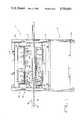
- FIG. 1is a partially broken-away front elevational view of an impingement food preparation oven incorporating a preferred embodiment of the present invention
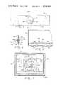
- FIG. 2is a fragmentary and broken-away top elevational view of the oven in FIG. 1;
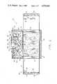
- FIG. 3is a fragmentary and broken-away side elevational view of the embodiment in FIG. 1;
- FIG. 4is a front elevational view of the fan of the preferred embodiment in FIG. 1;
- FIG. 5is an elevational view of the plenum front wall in the embodiment in FIG. 1 illustrating the conically-shaped projection
- FIG. 6is a sectional view of FIG. 5 taken along lines 6--6 and viewed in the direction of the arrows;
- FIG. 7is a broken-away elevational view looking through the plenum backwall opening at a plenum front wall having the conically-shaped projection;
- FIG. 8is an enlarged fragmentary and broken-away elevational view of an air duct
- FIG. 9is a sectional view of fig. 4 taken along line 9--9 and viewed in the direction of arrows;
- FIG. 10is an elevational view of the fan in FIG. 4;
- FIG. 11is an enlarged fragmentary and broken-away view of the outer nozzle plate of an air duct and a cover plate spaced thereapart;
- FIG. 12is an enlarged fragmentary and broken away view of the cover plate attached to the air duct in FIG. 11.
- impingement food preparation oven 20comprising stand assembly 22 movably mounted on casters 24 and cabinet assembly 26 mounted on stand assembly 22.
- stand assembly 22A more detailed description of stand assembly 22 as well as the manner of connections and attachment hereinafter described, is more fully provided in U.S. Pat. No. 4,462,383, for "IMPINGEMENT FOOD PREPARATION APPARATUS", and assigned to the assignee of the present patent application.
- U.S. Pat. No. 4,462,383is hereby incorporated by reference herein.
- Cabinet assembly 26includes enclosure 28 comprising insulated bottom wall 30, insulated top wall 31, insulated side walls 32, 34, insulated backwall 36, and door assembly 38 having insulated door 40 hingedly connected thereto.
- enclosure 28comprising insulated bottom wall 30, insulated top wall 31, insulated side walls 32, 34, insulated backwall 36, and door assembly 38 having insulated door 40 hingedly connected thereto.
- a more detailed description of a typical door assembly 38can be found in the aforementioned U.S. Pat. No. 4,462,383.
- a conveyor assembly 42is horizontally disposed through passageways (not shown) in side walls 32, 34, and comprises a conveyor frame 44 supporting a movable continuous belting 46 driven by means of drive shaft 48 with gears 50 and idler shaft 52 with gears 54.
- Drive shaft 48can be driven by any suitable means, such as an electric motor (not shown).
- Enclosure 28further includes a cooking chamber 56, in which conveyor assembly 42 is horizontally disposed, and elongated air duct 58 spaced above conveyor assembly 42 and elongated air duct 60 spaced below conveyor assembly 42.
- Air ducts 58, 60are connected to plenum 62 for receiving a flow of heated air therefrom.
- Plenum 62includes a tapering sidewall 64 (FIG. 2) connected to one end of mounting wall 66, which extends between side walls 32, 34, and tapering sidewall 68 connected to the other end of mounting wall 66.
- Plenum 62also includes a front wall 70 having a top opening 72 and a bottom opening 74 (FIGS. 3 and 7), and to which the open ends of air ducts 58, 60 are respectively connected.
- front wall 70is spaced apart from top wall 31 and bottom wall 30 as illustrated in FIGS. 1 and 3.
- a more detailed description of a suitable means of mounting air ducts 58, 60 and plenum 62 in enclosure 28can be found in U.S. Pat. No. 4,462,383.
- air duct 58has a plurality of nozzles 76 directed downwardly towards conveyor assembly 42 and air duct 60 has a plurality of nozzles 78 directed upwardly toward conveyor assembly 42.
- Nozzles 76, 78are designed to direct streams of columnated air against a food product conveyed by assembly 42.
- air ducts 58, 60include respective inner nozzles plates 80, 82 spaced apart from respective outer nozzles plates 84, 86. As illustrated in FIG. 8, inner nozzle plates 80, 82 and outer nozzle plates 84, 86 are spaced apart to provide columnated jets of air through their respective aligned nozzles 76, 78.
- plenum 62includes backwall 90 having opening 92 disposed therein.
- a cylindrical collar or sleeve 94is mounted in opening 92 and includes an annular flange 96 extending radially inwardly of opening 92 to form a second backwall opening 98.
- Front wall 70 of plenum 62includes a generally flat front surface 88.
- Flat surface 88is generally rectangularly shaped.
- Plenum 62further includes a conical member generally designated as 102.
- Conical member 102is centrally disposed on front wall 70 so as to project from flat front surface 88 in a generally axial direction towards scoop-type fan 178 will be described in more detail hereinafter.
- conical member 102includes a housing 104 in the shape of a truncated cone.
- Housing 104includes a generally conically-shaped wall 106 and an integral flat wall portion 108.
- Wall 106converges at an angle of convergence "a" of about 59°.
- Angle of convergence "a”is defined as being the angle between the central axis A-A of conical member 102 and the conically-shaped wall 106.
- the angle of convergencecan vary depending upon the specific application.
- a bolt 110has opposite ends 112 and 114.
- Bolt 110is mounted as by welding or the like at one end 112 thereof to the interior surface of housing 104 near flat portion 108.
- the other end of bolt 110extends through an aperture 116 in front wall 70.
- a nut 118is threadedly connected to bolt 110 at end 112 thereof.
- conical member 102can now be securely mounted to front wall 70.
- a ring member 152 having a peripheral sidewall 154 and an annular flange portion 156is tightly fitted in opening 98 such that a virtually air-tight fit exists between annular flange 96 and peripheral sidewall 154.
- Ring member 152is secured in place by mounting annular flange portion 156 on four studs 158, which have threaded end portions received through openings (not shown) in annular flange portion 156 and nuts 160 threaded thereon . Studs 158 extend inwardly from backwall 36 so as to properly mount ring member 152 in opening 98.
- Back wall 36has a frusto-conically shaped cavity 166 formed therein to provide internal motor shroud 164 and external motor shroud 166 for housing motor 168 secured to mounting bracket 170 (FIG. 2) of backwall 36.
- Motor 168has a motor shaft 172 rotatably extending through the inwardly extending portion 174 formed by cavity 162 in backwall 36.
- a heat conductor 176is secured to motor shaft 172 between motor 168 and portion 174 for absorbing heat from motor 168.
- scoop-type fan 178is secured to the remote end of motor shaft 162 by spider 180.
- Fan 178is made of a stainless steel material to permit it to satisfactorily operate at approximately 3000 RPM and at temperatures of approximately 600° F.
- Fan 178includes three blades 182 secured to spider 180, and each blade 182 is of generally tear-drop shape.
- Each blade 182includes a leading edge portion 184 generally defined between points A and B (FIG. 4) and which tapers to a point 186 in the direction of rotation, which in FIG. 4 is a clockwise rotation.
- Each blade 182further includes a trailing row portion 188 generally defined peripherally between points B and C.
- Each blade 182is relatively flat in its area near point 186 and smoothly increases in pitch angle from point B to point D.
- the pitch angleremains relatively constant between points D and C, but may also be allowed to increase in pitch between points B and C if desired.
- the maximum preferred pitch angleis between approximately 23° and about 25°.
- Heating of the air flow within enclosure 28is provided by heating coils 190 supported on backwall 36 and disposed behind and about fan 178. Heating coils 190 can be electrically operated in any suitable manner.
- nozzles 76are arranged in three sections 192, 194 and 196 in air duct 58, wherein each section 192, 194, 196 includes four rows of nozzles 76 extending the length of air duct 58.
- air duct 60includes four sections 198, 200, 202 and 204 of nozzles 78, each section 198, 200, 202, 204 containing four rows of nozzles 78 extending the length of air duct 60.
- a cover plate 206which can be of any desired size and shape, is placed over the selected nozzles to be shut off and removably attached thereto by locking pins 208 received in nozzles 76 as illustrated in FIGS. 15 and 16.
- Locking pins 208are secured to cover plate 206 by respective nut and bolt assemblies 210, and each locking pin 208 has a remote end formed as a loop having a diameter slightly greater than the diameter of nozzles 76, 78 such that the end snaps into place through nozzle 76 to removably secure cover plate 206 against inner nozzle plate 80.
- Each locking pin 208also includes a shank portion 214 having a predetermined length to ensure cover plate 206 remains firmly against nozzle plate 80, thereby preventing any vertical movement of cover plate 206 relative to plate 80.
- each blade 182scoops a substantially separate volume of air and forcibly moves it in an axial direction toward flat front surface 88, and because of the design of each blade 182, a succeeding blade 182 does not contact the volume of air moved by a preceding blade 182, and instead scoops another separate volume of air to be forcibly moved axially.
- This axially directed air flowprovides a more dynamic flow of heated air through plenum 62, thereby eliminating most heat loss associated with the above-described prior art ovens, and reduces the noise created by the flow of air being buffeted in plenum 62.
- each blade 182bites or scoops a volume of air, and upon continued rotation of blade 182, the trailing row portion 188 having a pitch angle between about 23°-25° forcibly directs or moves that volume of air axially forward.
- the smooth and uniform flow of the heated airis further assisted by curved peripheral sidewall 154 of ring member 152.
- the curvature of peripheral sidewall 154serves to smoothly guide and direct the air towards deflector surface 88.
- the conical member 102is positioned relative to fan 178 so that is is in generally axial alignment therewith.
- the conical member 102thus receives the air so as to smoothly and uniformly guide the air to a plurality of air ducts, such as air ducts 58, 60.
- the fan 178moves the air in a generally axial direction.
- the relative alignment of the fan and conical member 102provides for the air to impinge upon the exterior surface of 104. Due to the geometry of the conical member the air is gently directed or diverted radially outward as it moves in a general axial direction. The air still has an axial component of movement when it enters into air ducts 58, 60. This provides the desired alignment between the direction of heated air flow and air ducts 58, 60 resulting in a flow of heated air through nozzles 76, 78 that provides a uniform cooking temperature to a food product being conveyed by conveyor assembly 42.
- the circular geometry of conical member 102provides for the direction of a portion of the heated air flow to the corners and sides of air ducts 58, 60 to ensure uniform distribution of air flow along the width of ducts 58, 60.
Landscapes
- Life Sciences & Earth Sciences (AREA)
- Engineering & Computer Science (AREA)
- Food Science & Technology (AREA)
- Baking, Grill, Roasting (AREA)
Abstract
Description
Claims (12)
Priority Applications (1)
| Application Number | Priority Date | Filing Date | Title |
|---|---|---|---|
| US06/650,843US4556043A (en) | 1984-09-17 | 1984-09-17 | Air delivery system for an impingement food preparation oven including a conical air deflector |
Applications Claiming Priority (1)
| Application Number | Priority Date | Filing Date | Title |
|---|---|---|---|
| US06/650,843US4556043A (en) | 1984-09-17 | 1984-09-17 | Air delivery system for an impingement food preparation oven including a conical air deflector |
Publications (1)
| Publication Number | Publication Date |
|---|---|
| US4556043Atrue US4556043A (en) | 1985-12-03 |
Family
ID=24610546
Family Applications (1)
| Application Number | Title | Priority Date | Filing Date |
|---|---|---|---|
| US06/650,843Expired - Fee RelatedUS4556043A (en) | 1984-09-17 | 1984-09-17 | Air delivery system for an impingement food preparation oven including a conical air deflector |
Country Status (1)
| Country | Link |
|---|---|
| US (1) | US4556043A (en) |
Cited By (40)
| Publication number | Priority date | Publication date | Assignee | Title |
|---|---|---|---|---|
| US4701340A (en)* | 1985-12-09 | 1987-10-20 | Lincoln Foodservice Products, Inc. | Impingement and steam oven apparatus for preparing food products |
| US4753215A (en)* | 1987-01-14 | 1988-06-28 | Lincoln Foodservice Products, Inc. | Burner for low profile inpingement oven |
| US4757800A (en)* | 1987-01-14 | 1988-07-19 | Lincoln Foodservice Products, Inc. | Air flow system for a low profile impingement oven |
| US4873107A (en)* | 1986-12-24 | 1989-10-10 | Archer Air Industries, Inc. | Air impingement tunnel oven apparatus |
| US4881519A (en)* | 1988-07-18 | 1989-11-21 | Lincoln Foodservice Products, Inc. | Hot air oven having infra-red radiant surfaces |
| US4919477A (en)* | 1988-10-17 | 1990-04-24 | Pizza Hut, Inc. | Compact pizza preparation and delivery vehicle |
| US4924763A (en)* | 1988-10-17 | 1990-05-15 | Pizza Hut | Compact pizza oven |
| US4951648A (en)* | 1989-03-23 | 1990-08-28 | Tecogen, Inc. | Conveyor oven |
| US5040974A (en)* | 1990-03-27 | 1991-08-20 | Apv Baker Inc. | Internal air circulation system for lanham oven |
| US5231920A (en)* | 1991-09-19 | 1993-08-03 | G. S. Blodgett Corporation | Conveyor oven with uniform air flow |
| US5239917A (en)* | 1991-06-06 | 1993-08-31 | Genie Tech, Inc. | Oven |
| US5454295A (en)* | 1988-03-10 | 1995-10-03 | Pizza Hut, Inc. | Oven for baking pizza |
| US5551251A (en)* | 1995-02-08 | 1996-09-03 | York Food Systems | Impingement freezer |
| US5676044A (en)* | 1996-01-03 | 1997-10-14 | Lara, Jr.; George A. | Rotary air impingement oven |
| US5937845A (en)* | 1996-09-23 | 1999-08-17 | Gladd, Sr.; Andrew J. | Alternating horizontal air flow oven |
| US6195906B1 (en)* | 1999-10-18 | 2001-03-06 | Fedna Stoll | Air purification system and food dehydration unit |
| US6219937B1 (en) | 2000-03-30 | 2001-04-24 | George R. Culp | Reheaters for kilns, reheater-like structures, and associated methods |
| US6370792B1 (en) | 2000-09-01 | 2002-04-16 | George R. Culp | Structure and methods for introducing heated ari into a kiln chamber |
| US6467190B2 (en) | 2000-03-22 | 2002-10-22 | George R. Gulp | Drying kiln |
| EP1199963A4 (en)* | 1999-08-04 | 2002-10-30 | Frymaster Corp | High speed variable size toaster |
| US20030056658A1 (en)* | 1999-08-04 | 2003-03-27 | The Frymaster Corporation | High speed cooking device and method |
| US6557543B2 (en)* | 2001-06-27 | 2003-05-06 | Gas Research Institute | High pressure airflow and duct distribution system for a convection oven |
| EP1442660A1 (en) | 2003-01-24 | 2004-08-04 | Moretti Forni S.p.A. | Oven for the continuous cooking of food products |
| US20040177769A1 (en)* | 2003-03-12 | 2004-09-16 | Paloma Industries, Limited | Conveyor oven |
| US20050236402A1 (en)* | 2004-04-08 | 2005-10-27 | Maytag Corporation | Cooking appliance including combination heating system |
| US20060163238A1 (en)* | 2005-01-26 | 2006-07-27 | Miller R C | Modular cooking oven and related methods |
| USRE39828E1 (en) | 1995-06-26 | 2007-09-11 | Miller R Craig | Convection/impingement oven for continuously cooking food |
| US20080216812A1 (en)* | 2007-03-10 | 2008-09-11 | Dougherty Carl J | Compact conveyor oven |
| US7834299B2 (en) | 2004-12-14 | 2010-11-16 | Enodis Corporation | Impingement/convection/microwave oven and method |
| US20120014813A1 (en)* | 2010-07-16 | 2012-01-19 | US Sunlight Inc. | Method and Apparatus for Solar Attic Fan with Air Flow Guide |
| WO2013043285A1 (en)* | 2011-09-20 | 2013-03-28 | Appliance Innovation, Inc. | Matchbox oven |
| US20140199446A1 (en)* | 2013-01-11 | 2014-07-17 | Star Manufacturing International, Inc. | Split-Belt Conveyor Toaster |
| EP2870876A1 (en)* | 2013-11-12 | 2015-05-13 | Daub Backtechnik GmbH | Baking oven and retrofit kit for baking ovens |
| US9288997B2 (en) | 2011-03-31 | 2016-03-22 | Ovention, Inc. | Matchbox oven |
| US9326639B2 (en) | 2011-03-31 | 2016-05-03 | Ovention, Inc. | Oven having a rotating door |
| US9372006B2 (en) | 2013-05-06 | 2016-06-21 | Ovention, Inc. | Compact oven |
| US9480364B2 (en) | 2011-03-31 | 2016-11-01 | Ovention, Inc. | Oven having an H-shaped rotating door |
| WO2016200511A1 (en) | 2015-06-08 | 2016-12-15 | Appliance Innovation, Inc. | Convection oven having removable air pleunums |
| US11266152B2 (en)* | 2016-03-09 | 2022-03-08 | Dmp Enterprises Pty Ltd | Conveyer-type oven |
| US20220395139A1 (en)* | 2021-06-15 | 2022-12-15 | Jiangmen City Xinhui Henglong Innovative Housewares Co., Ltd. | Toaster |
Citations (17)
| Publication number | Priority date | Publication date | Assignee | Title |
|---|---|---|---|---|
| FR515884A (en)* | 1914-04-25 | 1921-04-08 | Crosse Plow Company | Plow |
| GB439249A (en)* | 1934-06-05 | 1935-12-03 | George Milne | Improvements relating to screw propellers |
| US2212041A (en)* | 1939-06-08 | 1940-08-20 | Iig Electric Ventilating Compa | Fan wheel |
| GB601160A (en)* | 1945-04-05 | 1948-04-29 | Victor Asarius Kennett | Improvements in or relating to propellers, fans and the like |
| CH276654A (en)* | 1949-08-19 | 1951-07-31 | Schlaepfer Robert | Roasting equipment, especially for sweet chestnuts. |
| US2616617A (en)* | 1949-10-07 | 1952-11-04 | Hill Harold | Air circulating device |
| US2841326A (en)* | 1954-06-14 | 1958-07-01 | Trane Co | Centrifugal fan |
| US3568331A (en)* | 1969-01-08 | 1971-03-09 | Greenbank Eng Co Ltd | Suction drying apparatus |
| US3656469A (en)* | 1969-07-17 | 1972-04-18 | Burger Eisenwerke Ag | Air-circulation apparatus for self-cleaning oven and the like |
| US3719180A (en)* | 1970-02-02 | 1973-03-06 | Capic Etablissements Caillarec | Device for heat treatment by way of forced gas convection, forming a bakery, pastry, pork-butchery oven or the like |
| US3978843A (en)* | 1974-01-09 | 1976-09-07 | Buderus'sche Eisenwerke Aktiengesellschaft | Food cooking oven with controlled air circulation |
| US4039278A (en)* | 1974-03-18 | 1977-08-02 | Andrew Denholm | Bakery oven |
| US4059399A (en)* | 1975-03-04 | 1977-11-22 | Bertin & Cie | Cooled tunnel-furnace with ground effect |
| DE3033685A1 (en)* | 1979-09-10 | 1981-03-19 | Hitachi, Ltd., Tokyo | Axial inflow cooling air impeller for air conditioner - has blades with specified contour to produce outflow component in radial direction |
| GB2078365A (en)* | 1980-06-26 | 1982-01-06 | Inventum Koninklijke Fab | Oven for heating foodstuffs in containers |
| US4438572A (en)* | 1982-06-09 | 1984-03-27 | Lincoln Manufacturing Co., Inc. | Heat duct support assembly for a food preparation oven and method |
| US4462383A (en)* | 1982-06-09 | 1984-07-31 | Lincoln Manufacturing Company, Inc. | Impingement food preparation apparatus |
- 1984
- 1984-09-17USUS06/650,843patent/US4556043A/ennot_activeExpired - Fee Related
Patent Citations (17)
| Publication number | Priority date | Publication date | Assignee | Title |
|---|---|---|---|---|
| FR515884A (en)* | 1914-04-25 | 1921-04-08 | Crosse Plow Company | Plow |
| GB439249A (en)* | 1934-06-05 | 1935-12-03 | George Milne | Improvements relating to screw propellers |
| US2212041A (en)* | 1939-06-08 | 1940-08-20 | Iig Electric Ventilating Compa | Fan wheel |
| GB601160A (en)* | 1945-04-05 | 1948-04-29 | Victor Asarius Kennett | Improvements in or relating to propellers, fans and the like |
| CH276654A (en)* | 1949-08-19 | 1951-07-31 | Schlaepfer Robert | Roasting equipment, especially for sweet chestnuts. |
| US2616617A (en)* | 1949-10-07 | 1952-11-04 | Hill Harold | Air circulating device |
| US2841326A (en)* | 1954-06-14 | 1958-07-01 | Trane Co | Centrifugal fan |
| US3568331A (en)* | 1969-01-08 | 1971-03-09 | Greenbank Eng Co Ltd | Suction drying apparatus |
| US3656469A (en)* | 1969-07-17 | 1972-04-18 | Burger Eisenwerke Ag | Air-circulation apparatus for self-cleaning oven and the like |
| US3719180A (en)* | 1970-02-02 | 1973-03-06 | Capic Etablissements Caillarec | Device for heat treatment by way of forced gas convection, forming a bakery, pastry, pork-butchery oven or the like |
| US3978843A (en)* | 1974-01-09 | 1976-09-07 | Buderus'sche Eisenwerke Aktiengesellschaft | Food cooking oven with controlled air circulation |
| US4039278A (en)* | 1974-03-18 | 1977-08-02 | Andrew Denholm | Bakery oven |
| US4059399A (en)* | 1975-03-04 | 1977-11-22 | Bertin & Cie | Cooled tunnel-furnace with ground effect |
| DE3033685A1 (en)* | 1979-09-10 | 1981-03-19 | Hitachi, Ltd., Tokyo | Axial inflow cooling air impeller for air conditioner - has blades with specified contour to produce outflow component in radial direction |
| GB2078365A (en)* | 1980-06-26 | 1982-01-06 | Inventum Koninklijke Fab | Oven for heating foodstuffs in containers |
| US4438572A (en)* | 1982-06-09 | 1984-03-27 | Lincoln Manufacturing Co., Inc. | Heat duct support assembly for a food preparation oven and method |
| US4462383A (en)* | 1982-06-09 | 1984-07-31 | Lincoln Manufacturing Company, Inc. | Impingement food preparation apparatus |
Cited By (64)
| Publication number | Priority date | Publication date | Assignee | Title |
|---|---|---|---|---|
| US4701340A (en)* | 1985-12-09 | 1987-10-20 | Lincoln Foodservice Products, Inc. | Impingement and steam oven apparatus for preparing food products |
| US4873107A (en)* | 1986-12-24 | 1989-10-10 | Archer Air Industries, Inc. | Air impingement tunnel oven apparatus |
| US4753215A (en)* | 1987-01-14 | 1988-06-28 | Lincoln Foodservice Products, Inc. | Burner for low profile inpingement oven |
| US4757800A (en)* | 1987-01-14 | 1988-07-19 | Lincoln Foodservice Products, Inc. | Air flow system for a low profile impingement oven |
| JPS63192411A (en)* | 1987-01-14 | 1988-08-09 | リンカーン・フードサービス・プロダクツ・インコーポレイテッド | Food cooking oven |
| US5454295A (en)* | 1988-03-10 | 1995-10-03 | Pizza Hut, Inc. | Oven for baking pizza |
| US4881519A (en)* | 1988-07-18 | 1989-11-21 | Lincoln Foodservice Products, Inc. | Hot air oven having infra-red radiant surfaces |
| US4919477A (en)* | 1988-10-17 | 1990-04-24 | Pizza Hut, Inc. | Compact pizza preparation and delivery vehicle |
| US4924763A (en)* | 1988-10-17 | 1990-05-15 | Pizza Hut | Compact pizza oven |
| US4951648A (en)* | 1989-03-23 | 1990-08-28 | Tecogen, Inc. | Conveyor oven |
| US5040974A (en)* | 1990-03-27 | 1991-08-20 | Apv Baker Inc. | Internal air circulation system for lanham oven |
| US5239917A (en)* | 1991-06-06 | 1993-08-31 | Genie Tech, Inc. | Oven |
| US5231920A (en)* | 1991-09-19 | 1993-08-03 | G. S. Blodgett Corporation | Conveyor oven with uniform air flow |
| US5551251A (en)* | 1995-02-08 | 1996-09-03 | York Food Systems | Impingement freezer |
| USRE39828E1 (en) | 1995-06-26 | 2007-09-11 | Miller R Craig | Convection/impingement oven for continuously cooking food |
| US5676044A (en)* | 1996-01-03 | 1997-10-14 | Lara, Jr.; George A. | Rotary air impingement oven |
| US6263693B1 (en) | 1996-09-23 | 2001-07-24 | Andrew J. Gladd, Sr. | Alternating horizontal air flow chiller |
| US5937845A (en)* | 1996-09-23 | 1999-08-17 | Gladd, Sr.; Andrew J. | Alternating horizontal air flow oven |
| US6595117B1 (en) | 1999-08-04 | 2003-07-22 | The Frymaster Corporation | High speed variable size toaster |
| EP1421885A1 (en)* | 1999-08-04 | 2004-05-26 | The Frymaster Corporation | High speed variable size toaster |
| US7424848B2 (en) | 1999-08-04 | 2008-09-16 | Lincoln Foodservice Products, Inc. | High speed cooking device and method |
| EP1199963A4 (en)* | 1999-08-04 | 2002-10-30 | Frymaster Corp | High speed variable size toaster |
| US20030056658A1 (en)* | 1999-08-04 | 2003-03-27 | The Frymaster Corporation | High speed cooking device and method |
| US20050109216A1 (en)* | 1999-08-04 | 2005-05-26 | Lincoln Foodservice Products, Inc. | High speed cooking device and method |
| US6817283B2 (en) | 1999-08-04 | 2004-11-16 | Lincoln Foodservice Products, Inc. | High speed cooking device and method |
| US6195906B1 (en)* | 1999-10-18 | 2001-03-06 | Fedna Stoll | Air purification system and food dehydration unit |
| US6652274B2 (en) | 2000-03-22 | 2003-11-25 | George R. Culp | Kiln and kiln-related structures, and associated methods |
| US6467190B2 (en) | 2000-03-22 | 2002-10-22 | George R. Gulp | Drying kiln |
| US6219937B1 (en) | 2000-03-30 | 2001-04-24 | George R. Culp | Reheaters for kilns, reheater-like structures, and associated methods |
| US6370792B1 (en) | 2000-09-01 | 2002-04-16 | George R. Culp | Structure and methods for introducing heated ari into a kiln chamber |
| US6557543B2 (en)* | 2001-06-27 | 2003-05-06 | Gas Research Institute | High pressure airflow and duct distribution system for a convection oven |
| EP1442660A1 (en) | 2003-01-24 | 2004-08-04 | Moretti Forni S.p.A. | Oven for the continuous cooking of food products |
| US20040177769A1 (en)* | 2003-03-12 | 2004-09-16 | Paloma Industries, Limited | Conveyor oven |
| US7059317B2 (en) | 2003-03-12 | 2006-06-13 | Paloma Industries, Limited | Conveyer oven |
| US20050236402A1 (en)* | 2004-04-08 | 2005-10-27 | Maytag Corporation | Cooking appliance including combination heating system |
| US7235763B2 (en)* | 2004-04-08 | 2007-06-26 | Aga Foodservice Group | Cooking appliance including combination heating system |
| US7834299B2 (en) | 2004-12-14 | 2010-11-16 | Enodis Corporation | Impingement/convection/microwave oven and method |
| US7838807B2 (en) | 2004-12-14 | 2010-11-23 | Enodis Corporation | Impingement/convection/microwave oven and method |
| US8071922B2 (en) | 2004-12-14 | 2011-12-06 | Enodis Corporation | Impingement/convection/microwave oven and method |
| US8093538B2 (en) | 2004-12-14 | 2012-01-10 | Enodis Corporation | Impingement/convection/microwave oven and method |
| US7220944B2 (en) | 2005-01-26 | 2007-05-22 | Miller R Craig | Modular cooking oven and related methods |
| US20060163238A1 (en)* | 2005-01-26 | 2006-07-27 | Miller R C | Modular cooking oven and related methods |
| US20080216812A1 (en)* | 2007-03-10 | 2008-09-11 | Dougherty Carl J | Compact conveyor oven |
| US8113190B2 (en)* | 2007-03-10 | 2012-02-14 | Turbochef Technologies, Inc. | Compact conveyor oven |
| US20120014813A1 (en)* | 2010-07-16 | 2012-01-19 | US Sunlight Inc. | Method and Apparatus for Solar Attic Fan with Air Flow Guide |
| US9681773B2 (en) | 2011-03-31 | 2017-06-20 | Ovention, Inc. | Oven having an H-shaped rotating door |
| US9326639B2 (en) | 2011-03-31 | 2016-05-03 | Ovention, Inc. | Oven having a rotating door |
| US9974312B2 (en) | 2011-03-31 | 2018-05-22 | Ovention, Inc. | Oven having a rotating door |
| US9642374B2 (en) | 2011-03-31 | 2017-05-09 | Ovention, Inc. | Matchbox oven |
| US9480364B2 (en) | 2011-03-31 | 2016-11-01 | Ovention, Inc. | Oven having an H-shaped rotating door |
| US9288997B2 (en) | 2011-03-31 | 2016-03-22 | Ovention, Inc. | Matchbox oven |
| US9730552B2 (en) | 2011-09-20 | 2017-08-15 | Ovention, Inc. | Oven cavity temperature lowering by forced air |
| WO2013043285A1 (en)* | 2011-09-20 | 2013-03-28 | Appliance Innovation, Inc. | Matchbox oven |
| US9723951B2 (en) | 2011-09-20 | 2017-08-08 | Ovention, Inc. | Matchbox oven with heat sink temperature control |
| US8733236B2 (en) | 2011-09-20 | 2014-05-27 | Ovention, Inc. | Matchbox oven |
| US8746134B2 (en) | 2011-09-20 | 2014-06-10 | Ovention, Inc. | Matchbox oven |
| US20140199446A1 (en)* | 2013-01-11 | 2014-07-17 | Star Manufacturing International, Inc. | Split-Belt Conveyor Toaster |
| US9372006B2 (en) | 2013-05-06 | 2016-06-21 | Ovention, Inc. | Compact oven |
| EP2870876A1 (en)* | 2013-11-12 | 2015-05-13 | Daub Backtechnik GmbH | Baking oven and retrofit kit for baking ovens |
| WO2016200511A1 (en) | 2015-06-08 | 2016-12-15 | Appliance Innovation, Inc. | Convection oven having removable air pleunums |
| EP3302191A4 (en)* | 2015-06-08 | 2019-02-27 | Alto-Shaam, Inc. | CONVECTION OVEN HAVING REMOVABLE AIR PLENUMS |
| US11266152B2 (en)* | 2016-03-09 | 2022-03-08 | Dmp Enterprises Pty Ltd | Conveyer-type oven |
| US20220395139A1 (en)* | 2021-06-15 | 2022-12-15 | Jiangmen City Xinhui Henglong Innovative Housewares Co., Ltd. | Toaster |
| US11771263B2 (en)* | 2021-06-15 | 2023-10-03 | Jiangmen City Xinhui Henglong Innovative Housewares Co., Ltd. | Toaster |
Similar Documents
| Publication | Publication Date | Title |
|---|---|---|
| US4556043A (en) | Air delivery system for an impingement food preparation oven including a conical air deflector | |
| US4626661A (en) | Air delivery system for an impingement food preparation oven | |
| EP0096159B1 (en) | Impingement food preparation apparatus | |
| US4450756A (en) | Fume exhauster device | |
| US4679542A (en) | Fan-plenum configuration | |
| US3312386A (en) | Fan | |
| US7325481B2 (en) | Cooking device with a fan and a water supply | |
| EP3493723B1 (en) | Autonomous apparatus for cooking food, and corresponding method | |
| EP2636955B1 (en) | A cooking oven provided for heat transfer by convection | |
| CA2276592C (en) | Improved heat gun fan assembly | |
| JPH06508744A (en) | microwave turntable convection heater | |
| US3978843A (en) | Food cooking oven with controlled air circulation | |
| KR20000057231A (en) | Blown Air Distributor for a Convection Oven | |
| EP0089762B1 (en) | Fan-plenum configuration | |
| EP1069420A2 (en) | Vertical wind tunnel | |
| DE19949731A1 (en) | Oven used for baking bread and other foods is fitted with ventilation chamber supplied with cooling air by radial fan in housing | |
| US4289945A (en) | Energy transmission and distribution system for a microwave oven | |
| US4144437A (en) | Microwave oven energy stirrer | |
| CN212085938U (en) | Motor cover of air frying cooking appliance and air frying cooking appliance with motor cover | |
| CN112704407A (en) | Hot air baffle structure for cooking device and oven | |
| JP3550171B2 (en) | Heat treatment device using impact heat transfer | |
| GB2373714A (en) | Steam cooker having a ventilating fan with openings therein | |
| EP3128182A1 (en) | Fan for ovens for cooking foods | |
| US3208642A (en) | Material pick-up nozzle | |
| KR200160296Y1 (en) | Humidifier of Mushroom Cultivator |
Legal Events
| Date | Code | Title | Description |
|---|---|---|---|
| AS | Assignment | Owner name:LINCOLN MANUFACTURING COMPANY, INC., 1111 NORTH HA Free format text:ASSIGNMENT OF ASSIGNORS INTEREST.;ASSIGNOR:BRATTON, RONALD E.;REEL/FRAME:004316/0570 Effective date:19840913 Owner name:LINCOLN MANUFACTURING COMPANY, INC., A CORP OF IND Free format text:ASSIGNMENT OF ASSIGNORS INTEREST;ASSIGNOR:BRATTON, RONALD E.;REEL/FRAME:004316/0570 Effective date:19840913 | |
| AS | Assignment | Owner name:LINCOLN FOODSERVICE PRODUCTS, INC. Free format text:CHANGE OF NAME;ASSIGNOR:LINCOLN MANUFACTURING COMPANY, INC.;REEL/FRAME:004634/0068 Effective date:19860409 | |
| FEPP | Fee payment procedure | Free format text:PAYOR NUMBER ASSIGNED (ORIGINAL EVENT CODE: ASPN); ENTITY STATUS OF PATENT OWNER: LARGE ENTITY | |
| FPAY | Fee payment | Year of fee payment:4 | |
| REMI | Maintenance fee reminder mailed | ||
| LAPS | Lapse for failure to pay maintenance fees | ||
| FP | Lapsed due to failure to pay maintenance fee | Effective date:19931205 | |
| STCH | Information on status: patent discontinuation | Free format text:PATENT EXPIRED DUE TO NONPAYMENT OF MAINTENANCE FEES UNDER 37 CFR 1.362 |