US4555790A - Digital modem having a monitor for signal-to-noise ratio - Google Patents
Digital modem having a monitor for signal-to-noise ratioDownload PDFInfo
- Publication number
- US4555790A US4555790AUS06/509,716US50971683AUS4555790AUS 4555790 AUS4555790 AUS 4555790AUS 50971683 AUS50971683 AUS 50971683AUS 4555790 AUS4555790 AUS 4555790A
- Authority
- US
- United States
- Prior art keywords
- signal
- signals
- modem
- noise
- monitor
- Prior art date
- Legal status (The legal status is an assumption and is not a legal conclusion. Google has not performed a legal analysis and makes no representation as to the accuracy of the status listed.)
- Expired - Lifetime
Links
- 238000012544monitoring processMethods0.000claimsdescription4
- 230000000694effectsEffects0.000abstractdescription5
- 230000002452interceptive effectEffects0.000abstractdescription3
- 238000001514detection methodMethods0.000description3
Images


Classifications
- H—ELECTRICITY
- H04—ELECTRIC COMMUNICATION TECHNIQUE
- H04L—TRANSMISSION OF DIGITAL INFORMATION, e.g. TELEGRAPHIC COMMUNICATION
- H04L1/00—Arrangements for detecting or preventing errors in the information received
- H04L1/20—Arrangements for detecting or preventing errors in the information received using signal quality detector
- H04L1/206—Arrangements for detecting or preventing errors in the information received using signal quality detector for modulated signals
- H—ELECTRICITY
- H04—ELECTRIC COMMUNICATION TECHNIQUE
- H04L—TRANSMISSION OF DIGITAL INFORMATION, e.g. TELEGRAPHIC COMMUNICATION
- H04L27/00—Modulated-carrier systems
- H04L27/32—Carrier systems characterised by combinations of two or more of the types covered by groups H04L27/02, H04L27/10, H04L27/18 or H04L27/26
- H04L27/34—Amplitude- and phase-modulated carrier systems, e.g. quadrature-amplitude modulated carrier systems
- H04L27/38—Demodulator circuits; Receiver circuits
Definitions
- the objective of the present inventionis to provide a device for direct monitoring of the signal-to-noise ratio in a digital modem by using some of the standard components of the modem but without interfering with the modem's normal operation.
- Another objectiveis to provide a device which uses relatively simple, easily available components.
- the modem according to this inventionis adapted to receive QAM-type signals from a digital communication network, said signals being represented by a signal constellation, the modem comprising means for determining the ideal signals corresponding to the received signals, and means for generating noise signals, said noise signals being the difference between said ideal and said received signals, means for generating the rms value of said noise signals and means for determining the signal-to-noise ratio. Since for signals located relatively far from the origin of said signal constellation the difference between the received and the ideal signals is due to noise, as well as phase and amplitude errors induced by the communication network, the monitoring means is adapted to respond only to the innermost signals, i.e. signals located relatively close to the origin, where the effects of said phase and amplitude errors are negligible.
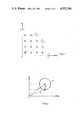
- FIG. 1shows the first quadrant of the signal constellation associated with a typical 64 point QAM-type modem
- FIG. 2is an enlarged portion of FIG. 1 showing the innermost point
- FIG. 3shows the subject device incorporated in a phase correction loop of a digital modem
- FIG. 4shows a digital low pass filter used in the device.
- the inventionshall now be described in reference to a 14400 b/s 64-point QAM-type digital modem, it being understood that the device may be easily adapted to other digital modems by one skilled in the art.
- the typical constellation of the signals by the modem of the type described above over a standard communications lineis shown in FIG. 1. Actually only the first quadrant is shown since the other three quadrants would obviously look similar.
- the ideal points for each possible signalhave been marked by an X and the closed oval loops drawn around each X delineates the signal space of a typical signal received by a modem of the type described above for that particular ideal signal X. These loops are due to phase jitter, frequency jitter, amplitude modulation and noise.
- the area of the loop around each point Xincreases as the radial component of X, i.e. its distance increases from the origin 0. Furthermore the eccentricity of these loops also increases with the radial component due to the increased effect of the phase jitter.
- points near the origin, and especially the innermost points such as point Aare surrounded by almost circular shapes. This indicates that the errors in the received signals corresponding to the innermost points are predominantly due to noise. Therefore, a signal-to-noise determination for the digital modem may be accomplished by analyzing only the signals corresponding to the innermost points.
- xis the rms value of the ideal signal X and n is the rms value of the noise N.
- FIG. 3One way of implementing the signal-to-noise ratio monitor is shown in FIG. 3.
- incoming signalsare fed into an equalizer 10 which feeds the equalized signals into a coordinate rotation circuit 20.
- Circuit 20rotates the signals by an angle ⁇ provided by phase error detection circuit 30 which is designed to eliminate phase errors. Details of the error detection circuit are disclosed in the commonly assigned Patent Application Ser. No. 407,451 filed on Aug. 12, 1982 which is hereby incorporated by reference.
- the rotated signals Yare also fed into a determinator circuit 40 which determines the ideal signals X corresponding to said signals Y.
- the determinatorgenerates a complex constant for each signal Y and sends it to the phase error detection circuit 30.
- the determinator circuitalso outputs demodulated data in accordance with the ideal signals X.
- the difference Dis fed into an error rotation circuit 60 which is provided to eliminate the effect of the coordinate rotation circuit 20, by rotating the difference D by an angle ⁇ .
- the output of circuit 60is fed into equalizer tap update circuit 70 and is in phase with the output of equalizer 10.
- the equalizer tap update circuit 70is used to adjust the taps of equalizer 10.
- the signal-to-noise ratio monitor circuit 80comprises an absolute value circuit 90 and a low-pass filter 100.
- the absolute value circuit 90generates the absolute value of the output D of circuit 60.
- the low pass filter 100is a standard digital filter with the components shown in FIG. 4.
- the input of the filter 100is connected to a first adder 110 and from there the signal is passed through a first multiplier 120, a second adder 130, and an integrator 140.
- the output of the integratorprovides the output of the filter 100, and is also fed back to second adder 130 and via second multiplier 150 to first adder 110.
- the multipliersmultiply their respective inputs by scaling factors. These factors are usually powers of 2 so that the multiplication can be easily accomplished by mere binary shifting of the inputs.
- the integrator 140is normally a digital memory device and it is operational only when it gets an ENABLE signal.
- This low-pass filter 100is usually referred to as a leaky integrator and its output does not overflow, nor does it return to zero with a zero input.
- the filtermay be used to obtain an output which is the average of the input signals taken over a period of time which is equal to the time constant of the filter.
- the net effect of combining the absolute value circuit 90 with low-pass filter 100is to produce an output which is the average of the absolute value of the input.
- This valueis then fed into divider 160 which also receives an input x from determinator 40 to generate the signal-to-noise ratio X/N.
Landscapes
- Engineering & Computer Science (AREA)
- Computer Networks & Wireless Communication (AREA)
- Signal Processing (AREA)
- Quality & Reliability (AREA)
- Digital Transmission Methods That Use Modulated Carrier Waves (AREA)
Abstract
Description
N=Yo-Xo (See FIG. 2),
(S/N)=20 log (.sup.x /n);
Claims (4)
Priority Applications (1)
| Application Number | Priority Date | Filing Date | Title |
|---|---|---|---|
| US06/509,716US4555790A (en) | 1983-06-30 | 1983-06-30 | Digital modem having a monitor for signal-to-noise ratio |
Applications Claiming Priority (1)
| Application Number | Priority Date | Filing Date | Title |
|---|---|---|---|
| US06/509,716US4555790A (en) | 1983-06-30 | 1983-06-30 | Digital modem having a monitor for signal-to-noise ratio |
Publications (1)
| Publication Number | Publication Date |
|---|---|
| US4555790Atrue US4555790A (en) | 1985-11-26 |
Family
ID=24027818
Family Applications (1)
| Application Number | Title | Priority Date | Filing Date |
|---|---|---|---|
| US06/509,716Expired - LifetimeUS4555790A (en) | 1983-06-30 | 1983-06-30 | Digital modem having a monitor for signal-to-noise ratio |
Country Status (1)
| Country | Link |
|---|---|
| US (1) | US4555790A (en) |
Cited By (20)
| Publication number | Priority date | Publication date | Assignee | Title |
|---|---|---|---|---|
| WO1986007223A1 (en)* | 1985-05-20 | 1986-12-04 | Telebit Corporation | Ensemble modem structure for imperfect transmission media |
| US4631738A (en)* | 1984-12-06 | 1986-12-23 | Paradyne Corporation | Gain tracker for digital modem |
| WO1987001531A1 (en)* | 1985-09-03 | 1987-03-12 | Motorola, Inc. | Digital radio frequency receiver |
| US4658210A (en)* | 1984-06-29 | 1987-04-14 | Racal Data Communications Inc. | Noninterruptive noise measurement |
| US4669091A (en)* | 1986-02-10 | 1987-05-26 | Rca Corporation | Adaptive multipath distortion equalizer |
| EP0233679A1 (en)* | 1986-01-18 | 1987-08-26 | Hewlett-Packard Limited | Non intrusive channel impairment analyser |
| US5029186A (en)* | 1987-05-19 | 1991-07-02 | Stiftelsen For Industriell Og Teknisk Forskning Ved Norges Tekniske Hogskole (Sinte) | Method of demodulation in digital communication systems with multipath propagation |
| FR2713855A1 (en)* | 1993-12-15 | 1995-06-16 | Alcatel Telspace | A method of detecting carrier recovery stall and determining the EB / NO ratio of a digital transmission link and device implementing this method. |
| WO1998028868A1 (en)* | 1996-12-24 | 1998-07-02 | Gte Government Systems Corporation | Method and apparatus for variably allocating upstream and downstream communication spectra |
| US6091787A (en)* | 1996-12-24 | 2000-07-18 | General Dynamics Government Systems Corporation | Symbol lock detector |
| US6212229B1 (en) | 1998-12-16 | 2001-04-03 | General Dynamics Government Systems Corporation | Adaptive pre-emphasis technique |
| US6304594B1 (en) | 1998-07-27 | 2001-10-16 | General Dynamics Government Systems Corporation | Interference detection and avoidance technique |
| GB2367221A (en)* | 2000-09-26 | 2002-03-27 | Motorola Inc | Method and apparatus for Signal Quality Estimation (SQE) in a communication system |
| EP0942565A3 (en)* | 1998-03-13 | 2003-04-16 | Sony Corporation | Phase estimation for fading channels |
| WO2004006527A1 (en)* | 2002-07-03 | 2004-01-15 | Telefonaktiebolaget Lm Ericsson (Publ) | Noise bqlqnced qam detection |
| US20050104684A1 (en)* | 2003-10-03 | 2005-05-19 | Applied Materials, Inc. | Planar integrated circuit including a plasmon waveguide-fed schottky barrier detector and transistors connected therewith |
| US20060013597A1 (en)* | 2004-07-14 | 2006-01-19 | Crivelli Diego E | Compensating impairments of optical channel using adaptive equalization |
| US20080165874A1 (en)* | 2007-01-05 | 2008-07-10 | Qualcomm Incorporated | High performance station |
| US20130251379A1 (en)* | 2004-07-14 | 2013-09-26 | Fundación Tarpuy | Adaptive equalization in coherent fiber optic communication |
| US9960866B1 (en)* | 2016-10-28 | 2018-05-01 | Samsung Electronics Co., Ltd | Method and apparatus for signal-to-noise ratio (SNR) estimation |
Citations (6)
| Publication number | Priority date | Publication date | Assignee | Title |
|---|---|---|---|---|
| US3693100A (en)* | 1971-04-09 | 1972-09-19 | Presearch Inc | Cumulative enhancement signal processor |
| US3889108A (en)* | 1974-07-25 | 1975-06-10 | Us Navy | Adaptive low pass filter |
| US3978407A (en)* | 1975-07-23 | 1976-08-31 | Codex Corporation | Fast start-up adaptive equalizer communication system using two data transmission rates |
| US4311963A (en)* | 1978-07-18 | 1982-01-19 | Matsushita Electric Industrial Co., Ltd. | Noise pulse suppressing system |
| US4447910A (en)* | 1981-06-02 | 1984-05-08 | Harris Corporation | Phase tracking correction scheme for high frequency modem |
| US4458355A (en)* | 1981-06-11 | 1984-07-03 | Hycom Incorporated | Adaptive phase lock loop |
- 1983
- 1983-06-30USUS06/509,716patent/US4555790A/ennot_activeExpired - Lifetime
Patent Citations (6)
| Publication number | Priority date | Publication date | Assignee | Title |
|---|---|---|---|---|
| US3693100A (en)* | 1971-04-09 | 1972-09-19 | Presearch Inc | Cumulative enhancement signal processor |
| US3889108A (en)* | 1974-07-25 | 1975-06-10 | Us Navy | Adaptive low pass filter |
| US3978407A (en)* | 1975-07-23 | 1976-08-31 | Codex Corporation | Fast start-up adaptive equalizer communication system using two data transmission rates |
| US4311963A (en)* | 1978-07-18 | 1982-01-19 | Matsushita Electric Industrial Co., Ltd. | Noise pulse suppressing system |
| US4447910A (en)* | 1981-06-02 | 1984-05-08 | Harris Corporation | Phase tracking correction scheme for high frequency modem |
| US4458355A (en)* | 1981-06-11 | 1984-07-03 | Hycom Incorporated | Adaptive phase lock loop |
Cited By (39)
| Publication number | Priority date | Publication date | Assignee | Title |
|---|---|---|---|---|
| US4658210A (en)* | 1984-06-29 | 1987-04-14 | Racal Data Communications Inc. | Noninterruptive noise measurement |
| US4631738A (en)* | 1984-12-06 | 1986-12-23 | Paradyne Corporation | Gain tracker for digital modem |
| US4731816A (en)* | 1985-05-20 | 1988-03-15 | Telebit Corporation | Ensemble modem structure for imperfect transmission media |
| WO1986007223A1 (en)* | 1985-05-20 | 1986-12-04 | Telebit Corporation | Ensemble modem structure for imperfect transmission media |
| US4679227A (en)* | 1985-05-20 | 1987-07-07 | Telebit Corporation | Ensemble modem structure for imperfect transmission media |
| WO1987001531A1 (en)* | 1985-09-03 | 1987-03-12 | Motorola, Inc. | Digital radio frequency receiver |
| EP0233679A1 (en)* | 1986-01-18 | 1987-08-26 | Hewlett-Packard Limited | Non intrusive channel impairment analyser |
| EP0366160A1 (en)* | 1986-01-18 | 1990-05-02 | Hewlett-Packard Limited | Non intrusive channel impairment analyser |
| EP0366159A1 (en)* | 1986-01-18 | 1990-05-02 | Hewlett-Packard Limited | Non intrusive channel impairment analyser |
| US4985900A (en)* | 1986-01-18 | 1991-01-15 | Hewlett-Packard | Non-intrusive channel-impairment analyzer |
| US4669091A (en)* | 1986-02-10 | 1987-05-26 | Rca Corporation | Adaptive multipath distortion equalizer |
| US5029186A (en)* | 1987-05-19 | 1991-07-02 | Stiftelsen For Industriell Og Teknisk Forskning Ved Norges Tekniske Hogskole (Sinte) | Method of demodulation in digital communication systems with multipath propagation |
| US6108373A (en)* | 1993-12-15 | 2000-08-22 | Alcatel Telspace | Process and device for detecting loss of carrier recovery and of determining the Eb/No ratio of a digital transmission link |
| FR2713855A1 (en)* | 1993-12-15 | 1995-06-16 | Alcatel Telspace | A method of detecting carrier recovery stall and determining the EB / NO ratio of a digital transmission link and device implementing this method. |
| EP0658993A1 (en)* | 1993-12-15 | 1995-06-21 | Alcatel Telspace | Method and apparatus for false-lock detection in carrier recovery and for SNR estimation (Eb/No) of a digital communication link |
| US6167095A (en)* | 1996-12-24 | 2000-12-26 | General Dynamics Government Systems Corporation | Method and apparatus for variably allocating upstream and downstream communication spectra |
| US5987069A (en)* | 1996-12-24 | 1999-11-16 | Gte Government Systems Corporation | Method and apparatus for variably allocating upstream and downstream communication spectra |
| WO1998028868A1 (en)* | 1996-12-24 | 1998-07-02 | Gte Government Systems Corporation | Method and apparatus for variably allocating upstream and downstream communication spectra |
| US6091787A (en)* | 1996-12-24 | 2000-07-18 | General Dynamics Government Systems Corporation | Symbol lock detector |
| EP0942565A3 (en)* | 1998-03-13 | 2003-04-16 | Sony Corporation | Phase estimation for fading channels |
| US6304594B1 (en) | 1998-07-27 | 2001-10-16 | General Dynamics Government Systems Corporation | Interference detection and avoidance technique |
| US6212229B1 (en) | 1998-12-16 | 2001-04-03 | General Dynamics Government Systems Corporation | Adaptive pre-emphasis technique |
| GB2367221A (en)* | 2000-09-26 | 2002-03-27 | Motorola Inc | Method and apparatus for Signal Quality Estimation (SQE) in a communication system |
| GB2367221B (en)* | 2000-09-26 | 2002-10-09 | Motorola Inc | Method and apparatus for signal quality estimation in a communication system |
| US7613253B2 (en) | 2002-07-03 | 2009-11-03 | Telefonaktiebolaget L M Ericsson (Publ) | Noise balanced QAM detection |
| WO2004006527A1 (en)* | 2002-07-03 | 2004-01-15 | Telefonaktiebolaget Lm Ericsson (Publ) | Noise bqlqnced qam detection |
| US20050104684A1 (en)* | 2003-10-03 | 2005-05-19 | Applied Materials, Inc. | Planar integrated circuit including a plasmon waveguide-fed schottky barrier detector and transistors connected therewith |
| US7170142B2 (en) | 2003-10-03 | 2007-01-30 | Applied Materials, Inc. | Planar integrated circuit including a plasmon waveguide-fed Schottky barrier detector and transistors connected therewith |
| US20060013597A1 (en)* | 2004-07-14 | 2006-01-19 | Crivelli Diego E | Compensating impairments of optical channel using adaptive equalization |
| US7623797B2 (en)* | 2004-07-14 | 2009-11-24 | Fundacion Tarpuy | Compensating impairments of optical channel using adaptive equalization |
| US20130251379A1 (en)* | 2004-07-14 | 2013-09-26 | Fundación Tarpuy | Adaptive equalization in coherent fiber optic communication |
| US8873974B2 (en)* | 2004-07-14 | 2014-10-28 | Fundación Tarpuy | Adaptive equalization in coherent fiber optic communication |
| WO2008086063A3 (en)* | 2007-01-05 | 2008-11-20 | Qualcomm Inc | Method and apparatus for processing data at a wireless station |
| US20080165874A1 (en)* | 2007-01-05 | 2008-07-10 | Qualcomm Incorporated | High performance station |
| US9253009B2 (en) | 2007-01-05 | 2016-02-02 | Qualcomm Incorporated | High performance station |
| US9960866B1 (en)* | 2016-10-28 | 2018-05-01 | Samsung Electronics Co., Ltd | Method and apparatus for signal-to-noise ratio (SNR) estimation |
| CN108023650A (en)* | 2016-10-28 | 2018-05-11 | 三星电子株式会社 | Method and apparatus for signal-to-noise ratio (SNR) estimation |
| CN108023650B (en)* | 2016-10-28 | 2021-01-15 | 三星电子株式会社 | Method and apparatus for signal-to-noise ratio estimation |
| TWI826352B (en)* | 2016-10-28 | 2023-12-21 | 南韓商三星電子股份有限公司 | Method and apparatus for signal-to-noise ratio (snr) estimation, manufacturing method and constructing method |
Similar Documents
| Publication | Publication Date | Title |
|---|---|---|
| US4555790A (en) | Digital modem having a monitor for signal-to-noise ratio | |
| US4024342A (en) | System for detecting digital data transmitted by modulating a carrier | |
| US5093847A (en) | Adaptive phase lock loop | |
| EP0238822B1 (en) | Composite qam-psk transmission system | |
| US5287067A (en) | Method and apparatus for demodulation with adaptive phase control in quasi-coherent detection | |
| US4577334A (en) | Digital data receiver including timing adjustment circuit | |
| CA2000007C (en) | Coherent phase shift keyed demodulator | |
| US3800228A (en) | Phase jitter compensator | |
| EP0934625B1 (en) | Numerical voltage controlled oscillator | |
| US5581582A (en) | Automatic frequency control method and apparatus therefor | |
| US4458355A (en) | Adaptive phase lock loop | |
| US4712221A (en) | Carrier recovery of modulated signals | |
| EP0032253B1 (en) | Demodulator carrier recovery loop and method for demodulating a signal | |
| JPH10327204A (en) | Phase locked loop circuit using equalizer | |
| US4054838A (en) | QAM phase jitter and frequency offset correction system | |
| US4061977A (en) | Phase tracking network | |
| US5315619A (en) | Carrier recovery processor for a QAM television signal | |
| US4035735A (en) | Demodulator comprising a phase shift circuit for controlling outputs of an automatic equalizer | |
| US6751270B1 (en) | Carrier frequency recovery apparatus capable of simultaneously reducing frequency offset and phase error and method of the same | |
| US6570441B1 (en) | Incoherent demodulator and method of incoherently demodulating an IF signal | |
| JP3636397B2 (en) | Jitter suppression circuit | |
| US6636570B1 (en) | Phase detection apparatus for compensating phase rotation error | |
| CA1111562A (en) | Method and device for measuring the slope of the envelope delay characteristic of a transmission channel and their application to the automatic equalizer selection technique | |
| US7116733B2 (en) | Automatic gain control circuit and automatic gain control method | |
| US4231094A (en) | Method and device for determining the phase intercept in a system employing phase-shift keying modulation |
Legal Events
| Date | Code | Title | Description |
|---|---|---|---|
| AS | Assignment | Owner name:PARADYNE CORPORATION, 8550 ULMERTON ROAD, LARGO, F Free format text:ASSIGNMENT OF ASSIGNORS INTEREST.;ASSIGNORS:BETTS, WILLIAM L.;MARTINEZ, KENNETH;REEL/FRAME:004153/0358 Effective date:19830615 | |
| STCF | Information on status: patent grant | Free format text:PATENTED CASE | |
| CC | Certificate of correction | ||
| FPAY | Fee payment | Year of fee payment:4 | |
| FEPP | Fee payment procedure | Free format text:PAYOR NUMBER ASSIGNED (ORIGINAL EVENT CODE: ASPN); ENTITY STATUS OF PATENT OWNER: LARGE ENTITY | |
| FEPP | Fee payment procedure | Free format text:PAYER NUMBER DE-ASSIGNED (ORIGINAL EVENT CODE: RMPN); ENTITY STATUS OF PATENT OWNER: LARGE ENTITY Free format text:PAYOR NUMBER ASSIGNED (ORIGINAL EVENT CODE: ASPN); ENTITY STATUS OF PATENT OWNER: LARGE ENTITY | |
| FPAY | Fee payment | Year of fee payment:8 | |
| AS | Assignment | Owner name:PARADYNE CORPORATION (FORMERLY KNOWN AS AT&T PARAD Free format text:ASSIGNMENT OF ASSIGNORS INTEREST;ASSIGNOR:LUCENT TECHNOLOGIES, INC.;REEL/FRAME:008167/0408 Effective date:19960731 | |
| FEPP | Fee payment procedure | Free format text:PAYER NUMBER DE-ASSIGNED (ORIGINAL EVENT CODE: RMPN); ENTITY STATUS OF PATENT OWNER: LARGE ENTITY Free format text:PAYOR NUMBER ASSIGNED (ORIGINAL EVENT CODE: ASPN); ENTITY STATUS OF PATENT OWNER: LARGE ENTITY | |
| AS | Assignment | Owner name:BANKAMERICA BUSINESS CREDIT, INC., CALIFORNIA Free format text:SECURITY AGREEMENT;ASSIGNOR:PARADYNE CORPORATION;REEL/FRAME:008261/0384 Effective date:19960731 | |
| FPAY | Fee payment | Year of fee payment:12 | |
| AS | Assignment | Owner name:FOOTHILL CAPITAL CORPORATION, CALIFORNIA Free format text:SECURITY AGREEMENT;ASSIGNOR:PARADYNE CORPORATION;REEL/FRAME:012211/0350 Effective date:20010716 |