US4555184A - Module for combination timepiece - Google Patents
Module for combination timepieceDownload PDFInfo
- Publication number
- US4555184A US4555184AUS06/557,036US55703683AUS4555184AUS 4555184 AUS4555184 AUS 4555184AUS 55703683 AUS55703683 AUS 55703683AUS 4555184 AUS4555184 AUS 4555184A
- Authority
- US
- United States
- Prior art keywords
- circuit
- analog
- substrate
- module
- timepiece
- Prior art date
- Legal status (The legal status is an assumption and is not a legal conclusion. Google has not performed a legal analysis and makes no representation as to the accuracy of the status listed.)
- Expired - Lifetime
Links
Images


Classifications
- G—PHYSICS
- G04—HOROLOGY
- G04C—ELECTROMECHANICAL CLOCKS OR WATCHES
- G04C3/00—Electromechanical clocks or watches independent of other time-pieces and in which the movement is maintained by electric means
- G04C3/008—Mounting, assembling of components
Definitions
- This inventionrelates generally to a hybrid type electronic timepiece of the type having both analog and digital displays, and more particularly to a combination timepiece being small, thin, attractive and allowing for a wide range of electronic displays.
- Electronic timepieces having a plurality of supplemental functionshave been developed rapidly and the combination of a timepiece including a digital display which is convenient to use, and an analog display which makes a nice appearance and is perferred by users for timekeeping, has been requested in the marketplace.
- a module construction for a combination timepieceincludes a power source, frequency source, circuit means, and an analog display including hands and an electronic liquid crystal display.
- the analog displayis conventional and covers the entire face of the timepiece in the conventional manner.
- the electronic displayoverlays the analog display with the center of the electronic display being located near the rotational center for the analog hand display.
- the electronic displayis substantially the size of the dial face. Thus, two full sized displays are provided and the analog display is visible through the liquid crystal display elements when the electronic display is not driven.
- Constructionis modular and an analog movement for supporting the hand display is positioned between a stiff reinforcement of metal and a spacer member connected thereto.
- Circuit meansare provided on both a thicker, stiff substrate and a thin film substrate laid on said stiffer substrate.
- the spacer memberseparates the substrates from the reinforcement and allows for positioning of the discrete electrical and mechanical components between the stiff reinforcement and the substrates.
- a circuit holder membersupports the substrates and connects by screws with the stiff reinforcement member such that a modular element is produced.
- An apertureis provided in the electrical circuit substrate through which a portion of the analog movement extends such that a thin timepiece is produced although both analog and digital displays are provided.
- the dial of the analog displayserves as a reflecting surface for the liquid crystal display further enabling a thin construction.
- Another object of this inventionis to provide an improved module for a combination timepiece which allows for small size and thin construction despite having both an analog and also a digital display.
- a further object of this inventionis to provide an improved module for a combination timepiece which allows for assembly and disassembly without stressing the connections between substrates and discrete components.
- FIG. 1is an assembly plan view of a module for a combination timepiece having a modular construction in accordance with the invention
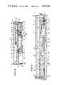
- FIGS. 2 and 3are sectional views of the module of FIG. 1;
- FIG. 4is an assembly plan view of the circuit means of the module of FIG. 1.
- This inventionrelates to a circuit and structural configuration for a combination timepiece, that is, a hybrid timepiece, having both analog hand display means and also an electronic display means. More particularly, the modular arrangement of circuits and structure is described with reference to FIGS. 1 through 4.
- FIG. 1includes an analog movement 1 which is held for positioning in the depth direction of the timepiece in engagement with a reinforcement 3 made of metal and having a central aperture and a portion 3a protruding therein.
- the analog movement 1includes a plate 2 having a recessed portion 2a for engagement with the protruding portion 3a of the reinforcement 3.
- the analog movement 1is also held in the length direction of the timepiece.
- Notched portions 2b, of which there are four such portions, provided on the periphery of the plate 2 in the width direction of the timepieceare supported by 4 semi-circular projection portions 3c of the reinforcement 3.
- the projecting portions 3calso extend into the central aperture of the reinforcement 3.
- the plate 2is pressed, by a plurality of protruding portions 4b extending from the spacer member 4, by fixing a metal circuit holder member 16 by a projecting portion 4a, of which there are three in number provided in the spacer member 4, and to the tubes 3b for a bridge screw, with a screw 17 of which there are also three. Therefore, the analog movement 1 is fixed in place.
- a battery 18 as a power sourceis positioned near the module corner, near the position of 11 o'clock of the analog movement, so that the largest possible planar space (FIGS. 1, 4) is obtained and the battery 18 does not touch the analog movement 1 as seen in the sectional views.
- a flexible resilient portion 19a of the battery negative terminal 19is in pressure contact with the cathode of the battery 18, and flexible resilient portion 19b is in pressure contact with an electrode terminal portion 11a provided on the circuit substrate 11.
- the battery negative terminal 19is positioned by an end extending into a hole 4d of the spacer member 4 (FIG. 3) and by an aperture in the terminal 19 receiving the projection 4c of the spacer member 4.
- the side of the battery 18is fixed to the circuit holder member 16 by elastically pressing a bent positive terminal 16a (FIG. 2). Further, the anode corner portion of the battery 18 is supported by a bent portion 16b provided at the end of the positive terminal 16a so as to prevent the battery from changing its position. Further, a flexible resilient portion 16c, provided on the circuit holder member 16, is in pressure contact with an electrode terminal portion 11b provided on the circuit substrate 11.
- the circuit holder member 16also has three resilient portions 16d, e, f. The resilient portion 16d engages with a button 20 of an external operational member (FIG. 3), and an electrode-portion 11(c) formed at the side surface of the circuit substrate 11 is contacted by pressing the button 20 so that an input signal is provided thereby.
- the elastic portion 16(e)makes pressure contact with a case back 22 having a piezoelectric element 21 fixed thereto so as to be electrically grounded.
- a lead terminal 23 for a buzzer for electrically connecting to the piezoelectric element 21 by pressing thereon,is supported by a projecting portion 4(e) of the spacer member 4.
- An end portion 23a of the lead terminal 23is supported between the thin film circuit substrate 14, having an electrode portion for conducting at that location, and the spacer member 4.
- the lead end portion 23amakes contact and conducts to provide a buzzer driving signal.
- a coil endis connected to an electrode pattern 27a of a coil lead substrate 27 fixed to a magnetic core 26 of a coil block 25.
- the thin film circuit substrate 14, provided with the electrode pattern for outputting the driving signals,is positioned so as to overlap with the electrode pattern of the lead substrate 27.
- a stator 30 and a magnetic core 26are fixed for attachment to a tube 29 for a bridge screw, fixed to the plate 2 by a screw 28 through an elastic portion 16f of the circuit holder member 16. The thickness of this screwed-together assembly varies substantially, because it is affected by variations or scatter in the thicknesses of the above mentioned components.
- a slit 14a(FIG. 4) is provided in the vicinity of the driving signal conductive connecting portion 14b of the circuit substrate 14, so that the degrees of freedom of movement in the vertical and longitudinal directions are increased, and the fixed portion of an electrode finger portion 15 is not adversely affected by a peel stress. Further, the spring width of the elastic portion 16f is made thin so as not to have a bad effect on the circuit.
- the screw 28is loosened without the circuit substrate 14 being peeled.
- the spacer member 4is positioned on the circuit substrate 11 surrounding the analog movement 1 and some gaps are provided between the spacer member 4 and the above mentioned circuit elements arranged within the space between the reinforcement 3 and the circuit holder member 16 by providing recessed portions and apertures. Further, an insulating coating is provided on the front and back sides of the circuit substrate 11 in order to attain high water vapor resistance and to insulate the circuit holder plate 16.
- a dial 31is fixed to the analog movement 1 by pressure fitting a dial foot 31a into a bridge washer 24.
- Hand display meansis constructed by fixing an hour hand 35, minute hand 36 and second hand 37 to an hour wheel, center wheel and pinion, and a fourth wheel and pinion (not shown) respectively, which are positioned through an opening 31b in the center of the dial 31 (FIG. 2).
- a liquid crystal panel 38 providing an electronic display meansis positioned to cover the entire hand display portion. That is, the face dimensions of the electronic liquid crystal display are not generally constrained by the face dimensions of the hand display.
- An elastic conductive rubber element 39(FIGS. 1, 2) is positioned between the circuit substrate 11 and an input signal receiving portion 38a provided at the external end, that is in the 12 through 6 o'clock region of the liquid crystal panel 38 when associated with an analog timepiece.
- the hooked portion 16g of the circuit holder member 16having an elastic portion, engages with a projecting portion 40a of a panel frame 40 so as to mechanically support the liquid crystal panel 38, which is electrically connected by the elastic force of the elastic conductive rubber member 39.
- a timepiece in accordance with this inventionis made not only thinner but also smaller in size by positioning the battery, circuit elements, etc., in an equal distribution around the analog movement 1, and by overlapping the film circuit substrate 14, on which the discrete components such as the condensers 12, and the like, are arranged on one plane, with the circuit substrate 11. Furthermore, the stiff circuit substrate 11 reduces the strains which occur during installation or other disturbances, in prior art designs when stiffness of the substrate is diminished by being made thin.
- this stiffnessefficiently prevents the condensers 12 from cracking or chipping.
- the coil 25 and circuit meansare electrically connected only by pressing against the circuit substrate 14 so that the number of components is decreased, and they are of small size. The effect of a scatter in dimensions of the components is reduced by providing the slit portion 14a in the thin circuit substrate 14 so that conduction is dependable and durable.
- the wiring patternis made simplified within the small space of a circuit substrate 11, provided with the central aperture, so that processing performance is improved by eliminating pattern chipping or a leak between patterns.
- the electrode finger portions 15 overhung from the external contours of the thin film circuit substrate 14,are structurally and electrically connected to the circuit substrate 11 by soldering, or the like, without using other components.
- the liquid crystal panel 38is positioned above the upper surfaces of the analog hands 35, 36, 37 so that a larger display area is provided as compared with conventional combination, that is, hybrid analog and digital, timepieces. Further, the combination timepiece in accordance with the invention is made thin, without damaging the appearance found in a conventional analog timepiece, by using the dial 31 in place of a reflector for the liquid crystal display. Light transmission of polarizing plates attached to the upper and lower surfaces of the liquid crystal panel 38 is more than 45% so as to satisfy the display quality and appearance of a digital timepiece and yet not damage the fine appearance of an analog timepiece.
- the dial surfaceis made rough so that incident light rays from the liquid crystal panel produce irregular reflections, and a dial whose color tone is very light is used.
- a combination timepiecehaving an appearance which is by no means inferior to that of a conventional analog timepiece, is provided.
- the surfaces of the handsare made dark in color so as to contrast with the appearance of the dial.
- the objective of good appearance and readabilitycan be attained by using a specular surface on the hands so that light is reflected.
- the appearance of the electronic display and the appearance of the analog displaycan be made to match each other by the above techniques.
- a superior analog displayis provided in a timepiece which comprises a liquid crystal panel having a wide display area over the hand display portion.
- the timepiececan remain thinner, smaller in size and less expensive than a conventional hybrid timepiece by using a simple construction. As a result, a more attractive timepiece is obtained.
Landscapes
- Physics & Mathematics (AREA)
- General Physics & Mathematics (AREA)
- Electromechanical Clocks (AREA)
- Electric Clocks (AREA)
Abstract
Description
Claims (11)
Applications Claiming Priority (2)
| Application Number | Priority Date | Filing Date | Title |
|---|---|---|---|
| JP57-215287 | 1982-12-07 | ||
| JP57215287AJPS59104586A (en) | 1982-12-07 | 1982-12-07 | Module structure of combination clock |
Publications (1)
| Publication Number | Publication Date |
|---|---|
| US4555184Atrue US4555184A (en) | 1985-11-26 |
Family
ID=16669815
Family Applications (1)
| Application Number | Title | Priority Date | Filing Date |
|---|---|---|---|
| US06/557,036Expired - LifetimeUS4555184A (en) | 1982-12-07 | 1983-12-01 | Module for combination timepiece |
Country Status (2)
| Country | Link |
|---|---|
| US (1) | US4555184A (en) |
| JP (1) | JPS59104586A (en) |
Cited By (14)
| Publication number | Priority date | Publication date | Assignee | Title |
|---|---|---|---|---|
| EP0272326A4 (en)* | 1986-04-22 | 1988-08-29 | Seiko Epson Corp | LOCKING DEVICE FOR TIMING DEVICE. |
| EP0361013A3 (en)* | 1988-09-28 | 1991-09-25 | Timex Corporation | Universal stepping motor gear, train module for a wrist instrument |
| US5369627A (en)* | 1987-07-21 | 1994-11-29 | Seiko Epson Corporation | Improvements in bearing and frame structure of a timepiece |
| US5617376A (en)* | 1992-12-02 | 1997-04-01 | Seiko Epson Corporation | Gear train structure of an electronic watch |
| EP0899636A1 (en)* | 1997-08-08 | 1999-03-03 | Junghans Uhren GmbH | Radio-controlled timepiece |
| EP0919886A1 (en)* | 1997-11-27 | 1999-06-02 | Andreas Haller GmbH & Co. KG Fabrik für Feinmechanik | Electric watch |
| US5923620A (en)* | 1996-05-16 | 1999-07-13 | Casio Computer Co., Ltd. | Module structure and electronic device |
| US6181648B1 (en)* | 1996-09-12 | 2001-01-30 | Citizen Watch Co., Ltd. | Electronic watch equipped with solar cell |
| US20030165086A1 (en)* | 2002-03-01 | 2003-09-04 | Brewer Donald R. | Compact color changing LCD watch |
| US20080013409A1 (en)* | 2006-07-11 | 2008-01-17 | Bland Diarmuid John St Cullom | Timepiece with overlapping, separately driven analog and mechanical functionality |
| US20100080088A1 (en)* | 2008-09-29 | 2010-04-01 | Eta Sa Manufacture Horlogere Suisse | Time base device for a watch |
| US20140328148A1 (en)* | 2013-05-06 | 2014-11-06 | Princo Middle East Fze | Wristwatch structure, electronic core for wristwatch, and method for manufacturing wristwatch |
| US20140328147A1 (en)* | 2013-05-06 | 2014-11-06 | Princo Middle East Fze | Wristwatch structure, electronic crown for wristwatch, and wristwatch having display |
| US20150078144A1 (en)* | 2013-09-18 | 2015-03-19 | Suzhou Lonshine Technologies Co., Ltd. | Integrated smart watch |
Families Citing this family (1)
| Publication number | Priority date | Publication date | Assignee | Title |
|---|---|---|---|---|
| DE3519819A1 (en)* | 1985-06-03 | 1986-12-11 | Timex Corp., Waterbury, Conn. | ELECTRIC SMALL CLOCK |
Citations (5)
| Publication number | Priority date | Publication date | Assignee | Title |
|---|---|---|---|---|
| US4247930A (en)* | 1978-05-18 | 1981-01-27 | Gebruder Junghans Gmbh | Timepiece with hybrid display |
| GB2052809A (en)* | 1979-05-08 | 1981-01-28 | Suwa Seikosha Kk | Timepiece |
| US4280209A (en)* | 1978-06-07 | 1981-07-21 | Bradley Time Division, Elgin National | Electronic alarm clock |
| US4355380A (en)* | 1979-06-28 | 1982-10-19 | Ebauches, S.A. | Electronic timepiece with auxiliary digital display |
| US4435087A (en)* | 1981-01-14 | 1984-03-06 | Matsushita Electric Works, Ltd. | Motor-driven movement for timepiece |
- 1982
- 1982-12-07JPJP57215287Apatent/JPS59104586A/enactiveGranted
- 1983
- 1983-12-01USUS06/557,036patent/US4555184A/ennot_activeExpired - Lifetime
Patent Citations (5)
| Publication number | Priority date | Publication date | Assignee | Title |
|---|---|---|---|---|
| US4247930A (en)* | 1978-05-18 | 1981-01-27 | Gebruder Junghans Gmbh | Timepiece with hybrid display |
| US4280209A (en)* | 1978-06-07 | 1981-07-21 | Bradley Time Division, Elgin National | Electronic alarm clock |
| GB2052809A (en)* | 1979-05-08 | 1981-01-28 | Suwa Seikosha Kk | Timepiece |
| US4355380A (en)* | 1979-06-28 | 1982-10-19 | Ebauches, S.A. | Electronic timepiece with auxiliary digital display |
| US4435087A (en)* | 1981-01-14 | 1984-03-06 | Matsushita Electric Works, Ltd. | Motor-driven movement for timepiece |
Cited By (19)
| Publication number | Priority date | Publication date | Assignee | Title |
|---|---|---|---|---|
| US4862432A (en)* | 1986-04-22 | 1989-08-29 | Shiojiri Kogyo Kabushiki Kaisha | Securing construction for timepiece |
| EP0272326A4 (en)* | 1986-04-22 | 1988-08-29 | Seiko Epson Corp | LOCKING DEVICE FOR TIMING DEVICE. |
| US5369627A (en)* | 1987-07-21 | 1994-11-29 | Seiko Epson Corporation | Improvements in bearing and frame structure of a timepiece |
| EP0361013A3 (en)* | 1988-09-28 | 1991-09-25 | Timex Corporation | Universal stepping motor gear, train module for a wrist instrument |
| US5617376A (en)* | 1992-12-02 | 1997-04-01 | Seiko Epson Corporation | Gear train structure of an electronic watch |
| US5923620A (en)* | 1996-05-16 | 1999-07-13 | Casio Computer Co., Ltd. | Module structure and electronic device |
| US6181648B1 (en)* | 1996-09-12 | 2001-01-30 | Citizen Watch Co., Ltd. | Electronic watch equipped with solar cell |
| EP0899636A1 (en)* | 1997-08-08 | 1999-03-03 | Junghans Uhren GmbH | Radio-controlled timepiece |
| EP0919886A1 (en)* | 1997-11-27 | 1999-06-02 | Andreas Haller GmbH & Co. KG Fabrik für Feinmechanik | Electric watch |
| US20030165086A1 (en)* | 2002-03-01 | 2003-09-04 | Brewer Donald R. | Compact color changing LCD watch |
| US7009915B2 (en)* | 2002-03-01 | 2006-03-07 | Fossil, Inc. | Compact color changing LCD watch |
| US20080013409A1 (en)* | 2006-07-11 | 2008-01-17 | Bland Diarmuid John St Cullom | Timepiece with overlapping, separately driven analog and mechanical functionality |
| US20100080088A1 (en)* | 2008-09-29 | 2010-04-01 | Eta Sa Manufacture Horlogere Suisse | Time base device for a watch |
| US8259537B2 (en)* | 2008-09-29 | 2012-09-04 | Eta Sa Manufacture Horlogère Suisse | Time base device for a watch |
| US20140328148A1 (en)* | 2013-05-06 | 2014-11-06 | Princo Middle East Fze | Wristwatch structure, electronic core for wristwatch, and method for manufacturing wristwatch |
| US20140328147A1 (en)* | 2013-05-06 | 2014-11-06 | Princo Middle East Fze | Wristwatch structure, electronic crown for wristwatch, and wristwatch having display |
| US9223296B2 (en)* | 2013-05-06 | 2015-12-29 | Princo Middle East Fze | Wristwatch structure, electronic crown for wristwatch, and wristwatch having display |
| US9256209B2 (en)* | 2013-05-06 | 2016-02-09 | Princo Middle East Fze | Wristwatch structure, electronic core for wristwatch, and method for manufacturing wristwatch |
| US20150078144A1 (en)* | 2013-09-18 | 2015-03-19 | Suzhou Lonshine Technologies Co., Ltd. | Integrated smart watch |
Also Published As
| Publication number | Publication date |
|---|---|
| JPS59104586A (en) | 1984-06-16 |
| JPS6240670B2 (en) | 1987-08-29 |
Similar Documents
| Publication | Publication Date | Title |
|---|---|---|
| US4555184A (en) | Module for combination timepiece | |
| US5265071A (en) | Electroluminescent watch dial support and connector assembly | |
| US4020627A (en) | Liquid crystal display electronic watch | |
| US4281406A (en) | Water-proof case for digital electronic timepieces | |
| US4068464A (en) | Shock resistant wristwatch module | |
| US4218872A (en) | Display device for timepiece | |
| US20230205143A1 (en) | Electronic device and method for assembling electronic device | |
| JP7487729B2 (en) | Electronics | |
| JP4360633B2 (en) | In particular, a control device for a push part for a watch, and a portable electronic device including the device | |
| JPH0330872Y2 (en) | ||
| GB2062304A (en) | Key Input Device for Electronic Timepiece Calculator | |
| JP4814007B2 (en) | clock | |
| JP2019105627A (en) | Timepiece comprising electric motor secured to attachment plate | |
| JPH0513119Y2 (en) | ||
| JP2002323581A (en) | Electronic wrist watch with sensor | |
| JPS6217747Y2 (en) | ||
| JPS6324470Y2 (en) | ||
| US20230418232A1 (en) | Arm wearable device and timepiece | |
| JP3236870B2 (en) | Watch structure | |
| JPH0139070B2 (en) | ||
| JPH08179061A (en) | Storage structure for acoustic device | |
| JPH082637Y2 (en) | Small pointer display type quartz watch | |
| JP2547329Y2 (en) | Electronic watch shield structure | |
| JPS6244386Y2 (en) | ||
| JPS6225742Y2 (en) |
Legal Events
| Date | Code | Title | Description |
|---|---|---|---|
| AS | Assignment | Owner name:SHIOJIRI KOGYO KABUSHIKI KAISHA, 3-5, OWA, 3-CHOME Free format text:ASSIGNMENT OF ASSIGNORS INTEREST.;ASSIGNOR:FUJIMORI, MOTOYUKI;REEL/FRAME:004203/0609 Effective date:19831118 Owner name:SHIOJIRI KOGYO KABUSHIKI KAISHA, 3-5, OWA, 3-CHOME Free format text:ASSIGNMENT OF ASSIGNORS INTEREST;ASSIGNOR:FUJIMORI, MOTOYUKI;REEL/FRAME:004203/0609 Effective date:19831118 | |
| STCF | Information on status: patent grant | Free format text:PATENTED CASE | |
| FEPP | Fee payment procedure | Free format text:PAYOR NUMBER ASSIGNED (ORIGINAL EVENT CODE: ASPN); ENTITY STATUS OF PATENT OWNER: LARGE ENTITY | |
| FPAY | Fee payment | Year of fee payment:4 | |
| FEPP | Fee payment procedure | Free format text:PAYER NUMBER DE-ASSIGNED (ORIGINAL EVENT CODE: RMPN); ENTITY STATUS OF PATENT OWNER: LARGE ENTITY Free format text:PAYOR NUMBER ASSIGNED (ORIGINAL EVENT CODE: ASPN); ENTITY STATUS OF PATENT OWNER: LARGE ENTITY | |
| FEPP | Fee payment procedure | Free format text:PAYOR NUMBER ASSIGNED (ORIGINAL EVENT CODE: ASPN); ENTITY STATUS OF PATENT OWNER: LARGE ENTITY Free format text:PAYER NUMBER DE-ASSIGNED (ORIGINAL EVENT CODE: RMPN); ENTITY STATUS OF PATENT OWNER: LARGE ENTITY | |
| REFU | Refund | Free format text:REFUND PROCESSED. MAINTENANCE FEE HAS ALREADY BEEN PAID (ORIGINAL EVENT CODE: R160); ENTITY STATUS OF PATENT OWNER: LARGE ENTITY | |
| FPAY | Fee payment | Year of fee payment:8 | |
| FPAY | Fee payment | Year of fee payment:12 |