US4554744A - Switch assembly for riflescope - Google Patents
Switch assembly for riflescopeDownload PDFInfo
- Publication number
- US4554744A US4554744AUS06/567,043US56704383AUS4554744AUS 4554744 AUS4554744 AUS 4554744AUS 56704383 AUS56704383 AUS 56704383AUS 4554744 AUS4554744 AUS 4554744A
- Authority
- US
- United States
- Prior art keywords
- battery
- switch member
- switch
- light source
- cover
- Prior art date
- Legal status (The legal status is an assumption and is not a legal conclusion. Google has not performed a legal analysis and makes no representation as to the accuracy of the status listed.)
- Expired - Fee Related
Links
- 230000003287optical effectEffects0.000claimsdescription12
- 230000013011matingEffects0.000claimsdescription4
- 238000010276constructionMethods0.000claims1
- 239000000428dustSubstances0.000abstractdescription4
- 241001465754MetazoaSpecies0.000description5
- 239000000463materialSubstances0.000description3
- 239000004033plasticSubstances0.000description3
- 239000004417polycarbonateSubstances0.000description3
- 229920000515polycarbonatePolymers0.000description3
- 238000007789sealingMethods0.000description3
- 238000010586diagramMethods0.000description2
- 239000002184metalSubstances0.000description2
- NDVLTYZPCACLMA-UHFFFAOYSA-Nsilver oxideChemical compound[O-2].[Ag+].[Ag+]NDVLTYZPCACLMA-UHFFFAOYSA-N0.000description2
- 229920002799BoPETPolymers0.000description1
- 239000005041Mylar™Substances0.000description1
- 230000000712assemblyEffects0.000description1
- 238000000429assemblyMethods0.000description1
- 230000005540biological transmissionEffects0.000description1
- 239000003086colorantSubstances0.000description1
- 150000001875compoundsChemical class0.000description1
- 230000003292diminished effectEffects0.000description1
- 238000005562fadingMethods0.000description1
- 238000005286illuminationMethods0.000description1
- 239000011810insulating materialSubstances0.000description1
- 239000012528membraneSubstances0.000description1
- 238000000465mouldingMethods0.000description1
- 230000000422nocturnal effectEffects0.000description1
- 239000002985plastic filmSubstances0.000description1
- 229920006255plastic filmPolymers0.000description1
- 238000004382pottingMethods0.000description1
- 230000000717retained effectEffects0.000description1
- 229910001923silver oxideInorganic materials0.000description1
Images

Classifications
- F—MECHANICAL ENGINEERING; LIGHTING; HEATING; WEAPONS; BLASTING
- F41—WEAPONS
- F41G—WEAPON SIGHTS; AIMING
- F41G1/00—Sighting devices
- F41G1/38—Telescopic sights specially adapted for smallarms or ordnance; Supports or mountings therefor
- F—MECHANICAL ENGINEERING; LIGHTING; HEATING; WEAPONS; BLASTING
- F41—WEAPONS
- F41G—WEAPON SIGHTS; AIMING
- F41G1/00—Sighting devices
- F41G1/30—Reflecting-sights specially adapted for smallarms or ordnance
- F—MECHANICAL ENGINEERING; LIGHTING; HEATING; WEAPONS; BLASTING
- F41—WEAPONS
- F41G—WEAPON SIGHTS; AIMING
- F41G1/00—Sighting devices
- F41G1/32—Night sights, e.g. luminescent
- F41G1/34—Night sights, e.g. luminescent combined with light source, e.g. spot light
- F41G1/345—Night sights, e.g. luminescent combined with light source, e.g. spot light for illuminating the sights
- G—PHYSICS
- G02—OPTICS
- G02B—OPTICAL ELEMENTS, SYSTEMS OR APPARATUS
- G02B27/00—Optical systems or apparatus not provided for by any of the groups G02B1/00 - G02B26/00, G02B30/00
- G02B27/32—Fiducial marks and measuring scales within the optical system
- G02B27/34—Fiducial marks and measuring scales within the optical system illuminated
Definitions
- Telescope sights or riflescopesare used by shooters to enable accurate aiming of firearms such as rifles, pistols, shotguns and the like. These optical sights are typically mounted in a elongated tubular barrel or housing carrying conventional ocular and objective lens systems. An erector-lens system is provided between the ocular and objective systems to provide an erect target image for viewing by the shooter. Windage and elevation adjustments permit the sight to be compensated for targets at varying ranges.
- a conventional riflescopeincludes a reticle, typically of cross hair or post form, which is seen by the shooter in silhouette and superimposed over the target image. The position of the firearm is adjusted until the reticle is positioned on a target-image aiming point.
- the primary advantage of an optical sightis that the target image and reticle are in the same focal plane, eliminating any need for the shooter to shift eye focus between sight and target as must be done with conventional open sights on a rifle.
- the optical sightmay provide fixed or variable magnification of the target image, but such magnification is not an essential feature and is subsidiary to the primary goal of providing a target image and aiming reticle in a single focal plane.
- the "fading reticle" problemis solved by illuminating the recticle itself (e.g., electrically heated incandescent reticles have been proposed), or preferably by providing a luminous dot or other mark at the aiming point of the sight. Details of the latter solution are shown in U.S. Pat. No. 3,672,782, the disclosure of which is incorporated herein by reference. Briefly, this patent shows a riflescope with a battery-operated internal lamp which projects a luminous reticle pattern (dot, cross hair, etc.) on the sight field of view and centered on the sight aiming point.
- a luminous reticle patterndot, cross hair, etc.
- the present inventionis directed to an improved illuminated-reticle riflescope having a very compact battery-housing and actuating-switch assembly which enhances the styling of the instrument, and is simple and convenient for the shooter to use.
- the actuating switchis relatively large for ease of operation when the shooter is wearing heavy gloves, and the switch also serves as a removable closure for the battery housing, enabling rapid and tool-free battery replacement.
- the removable closureshelters the batteries and switch elements from moisture and dirt, and essentially hermetic sealing of the riflescope interior is not affected by use of the invention.
- the term "riflescope”is used herein to designate any form of optical sighting device as previously described. That is, the term is used in a generic sense to mean any optical aiming device, whether used on a rifle, pistol, shotgun, archery bow, or the like.
- this inventionrelates to an improved switch assembly and battery housing for a riflescope having a light source to provide a luminous aiming point when poor lighting conditions prevent effective use of a normal aiming reticle in the sight field of view.
- the switch and battery compartmentare mounted in a convenient position adjacent the riflescope eyepiece to avoid interference with mounting components of the riflescope, and to enable easy actuation by the hunter.
- the battery compartment or boxis protected against the weather by a cover member and a slidably mounted switch member captively (but releasably) engaged with the box.
- a high-friction detent meansis provided to prevent inadvertent shifting of switch position by firearm recoil forces.
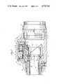
- FIG. 1is a side elevation of a riflescope incorporating the invention
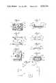
- FIG. 2is a top view of the assembly at the left end of FIG. 1;
- FIG. 3is an end view taken from the left end of FIG. 2;
- FIG. 4is a pictorial view of the assembly shown in FIGS. 2 and 3;
- FIG. 5is a sectional elevation of the assembly
- FIG. 6is a top view of a battery housing block
- FIG. 7is a side view of the battery block
- FIG. 8is an end view of the battery block
- FIG. 9is a top view of a cover member
- FIG. 10is a sectional view on line 10--10 of FIG. 9;
- FIG. 11is a bottom view of a switch member
- FIG. 12is a sectional end view of an assembled battery block, cover member, and switch member.
- FIG. 13is a circuit diagram pertaining to the assembly.
- a riflescope 10according to the invention is shown in FIG. 1, and it includes a central body tube 11 with an enlarged end 12 which supports an objective lens 13 (shown in phantom line).
- a conventional erector-lens system(not shown) is positioned within body tube 11, and the usual windage and elevation adjustments which cooperate with the erector-lens assembly are housed within capped turrets 14 on the body tube.
- a conventional ocular-lens assembly 16is mounted on an end of the riflescope opposite objective lens 13, and is locked in position by a knurled ring 17. Positioned between the ocular-lens assembly and turrets 14 is a rotatable power-change ring 18 for varying the magnification of the riflescope. It is unnecessary, however, that the riflescope be of a variable-power type, and the invention disclosed herein is equally useful in a riflescope of fixed magnification.
- housing 20Positioned between ocular-lens assembly 16 and power-change ring 18 is a hollow and generally cylindrical housing 20 shown in greater detail in FIGS. 2-4, and in the sectional view of FIG. 5.
- housing 20has a cylindrical foward portion 21 having internal threads 22 to receive the threaded rear end of body tube 11.
- a generally cylindrical rear portion 23 of the housingis similarly provided with internal threads 24 to receive externally-threaded ocular-lens assembly 16.
- Power-change ring 18is rotatably mounted on the outer surface of forward portion 21, and these parts are sealed by a pair of O-ring seals 25 to prevent entry of moisture or dust into the interior of the riflescope.
- a reticle mounting cell 28is positioned within housing 20, and is secured by screws 29 to the rear end of a tubular extension 30 of body tube 11.
- a sighting reticle 31which may be of the usual cross-hair style or any other conventional type.
- a semitransparent film-like pellicle 32oriented at an angle to an optical axis 33 of the riflescope. If desired, a partially reflecting mirror or equivalent optical arrangement may be substituted for the pellicle. In either case, the function of this optical component is to transmit light rays from the target toward the riflescope eyepiece, while simultaneously permitting reflection of an internally introduced light beam toward the eyepiece.
- a suitable pelliclewill have about 95 percent transmission and about 5 percent reflection of incident light.
- a small hollow block 35within which is secured a mounting tube 36 supporting a light source 37.
- the light sourcemay be a small incandescent lamp, but is preferably a conventional light-emitting diode which is selected to emit red light.
- An inner end of mounting tube 36is closed by a disk 38 having a small central aperture 39 which forms a narrow beam of light (suggested by dashed line 37A in FIG. 5) from source 37.
- a small shield 40is secured to the upper part of housing 20 just behind block 35 to prevent interference of stray light from light source 37 with the field of view seen through the riflescope eyepiece.
- a pair of integrally formed, laterally elongated and longitudinally spaced-apart front and rear walls 43 and 44extend upwardly from the upper surface of housing 20.
- Forward wall 43is positioned adjacent power change ring 18, and has a flat inner surface 45 which is perpendicular to the riflescope optical axis.
- rear wall 44has a flat inner surface 46 which is parallel to surface 45.
- the outer surface of housing 20 between the lower ends of surfaces 45 and 46is formed as a flat base surface 47. Surfaces 45-47 thus form an opensided saddle-like rectangular channel 48.
- a battery compartment or box 50makes a snug fit between inner wall surfaces 45 and 46, and is secured against base surface 47 by screws 51 (FIG. 6). As shown in FIGS. 6-8, the battery box is rectangular in planform, and defines a pair of upwardly opening cylindrical recesses 52 for receiving a pair of miniature batteries 53 (FIG. 5). A metal eyelet 54 in the base of each recess forms one contact for each battery.
- the undersurface of the battery boxdefines a recess 55 within which are positioned connecting wires 57 and a voltage-dropping resistor 58 placing the batteries, resistor, and light source in series connection as shown in the schematic diagram in FIG. 13.
- recess 55is filled with a potting compound (not shown) after the connecting wires and resistor are installed.
- Battery box 50has outwardly sloping and downwardly diverging sidewalls 59, each of which terminates in an inwardly V-shaped and longitudinally extending channel 60.
- An integrally formed and centrally positioned protrusion or detent button 61extends from each side of the battery box within channels 60.
- An upper surface 63 of the battery boxis generally flat, and the front and rear ends of this upper surface define laterally extending shallow recesses 64.
- a flat gasket seal 65is positioned between the undersurface of the battery box and base surface 47 of channel 48 to prevent entry of moisture or dust into the interior of the riflescope.
- An opening 66is formed through the gasket seal and base surface 47 to enable connection of wires 57 to light source 37.
- a battery-box cover member 70(FIGS. 5, 9-10, and 12) is internally configured to fit snugly over diverging sidewalls 59 of the battery box.
- the cover memberhas a flat top panel 71 with a rectangular and centrally positioned window-like opening 72 therethrough.
- a pair of diverging sidewalls 73extend downwardly from top panel 71 at an angulation matching the sloping side wall surfaces on the battery box.
- a shallow downwardly extending lip 74extends between the side walls at each end of the top panel. As shown in FIG. 5, lips 74 seat in recesses 64 of the battery box to aid in sealing these components and to prevent relative longitudinal motion therebetween.
- a switch member 77(FIGS. 1-2 and 4-5) is internally configured to make a mating slip fit over the upper surface of cover member 70. As shown in greater detail in FIGS. 11-12, the switch member is generally rectangular in planform, and has top panel 78 with a rounded upper surface 79 defining a series of longitudinally spaced lateral ribs and grooves 80 which provide a good gripping surface.
- each side wall 81Extending downwardly from side edges of the top panel 78 are a pair of diverging sidewalls 81 which are angled to match the slope of sidewalls 73 on the cover member.
- the lower end of each side wall 81defines an inwardly extending and generally V-shaped rib 83 shaped to engage mating channels 60 on the battery box (FIG. 12).
- the switch memberis preferably molded from a slightly resilient plastic material (polycarbonate is suitable) so sidewalls 81 can be slightly flexed apart to snap the switch member over the top of the battery box.
- a metallic contact 85is secured to the undersurface of the switch-member top panel, and the contact has a pair of longitudinally spaced resilient arms 86 extending downwardly from the top panel. These contact arms bear against the upper surfaces of batteries 53 as shown in FIG. 5 where the arms complete an electrical contact between the two batteries.
- a rearward positioning of the switch member within channel 48(FIG. 5) shifts forward contact arm 86 away from the electrically conductive portion of forward battery 53, and thereby breaks the circuit to extinguish light source 37.
- the switch memberis in a forward position against surface 45 of front wall (e.g., FIG. 4) the contact arms complete a circuit between the batteries to energize the light source.
- a pair of longitudinally spaced detent recesses 87are formed in each rib 83 of the switch member to cooperate with detent buttons 61 on the battery box.
- the ON and OFF positions of the switch memberare thus defined by the seating of buttons 61 in the respective detent recesses.
- housing 20(including integrally formed forward and rear walls 43 and 44) is preferably a diecast metal part.
- Pellicle 32is a membrane of Mylar or equivalent plastic film.
- Battery box 50is made of an insulating material, and is preferably a molding of polycarbonate or an equivalent plastic.
- cover and switch members 70 and 77can be conveniently and economically molded from a polycarbonate or equivalent plastic material.
- Batteries 53are preferably Type 76 silver-oxide or alkaline batteries of a commercially available miniature style.
- the battery box cover memberpreferably includes ON and OFF markings at opposite ends of top panel 78, and the upper surface of the top panel may be in contrasting colors to indicate the condition of the switch.
- the portion of the top panel bearing the OFF legendmay be black in color, and the opposite end portion bearing the ON legend may be red to indicate switch actuation.
- switch contact 85When the riflescope is used under normal daylight shooting conditions, switch contact 85 is maintained in the OFF position with switch member 77 in a fully rearward position (toward the eyepiece) within channel 48.
- the switch memberWhen lighting conditions deteriorate to the point where the normal sighting reticle is no longer clearly visible in the shooter's field of view through the riflescope, the switch member is moved to the ON position to close the circuit between the batteries and light source 37. A narrow beam of light is then projected through aperture 39 onto the surface of pellicle 32 to be reflected through the eyepiece toward the shooter's eye.
- the light source and pellicleare aligned such that the resulting bright spot of light is exactly superimposed on the aiming point (for example, the intersection of a cross-hair recticle) of the riflescope.
- the shooteris thus able to substitute the luminous dot in the field of view for the normal reticle aiming point, and to maintain proper aiming of the sight and associated firearm toward the target.
- the intensity of the luminous dotshould be quite low to avoid interference with the target image, and dropping resistor 58 (typically about 750 ohms) is inserted in series connection with the batteries and lamp to provide the desired intensity level.
- the light sourceis a red-emitting LED to further minimize interference with the shooter's vision and target image under diminished lighting conditions.
- Cover and switch members 70 and 77further provide a showerproof enclosure for the battery housing, shielding the battery and switch components from dirt and rain. The cover and switch members thus provide both a switching function, and a sheltering function for the riflescope illumination system.
- Battery replacementis easily done by outwardly flexing sidewalls 81 of the switch member so the switch and cover members can be removed from the battery box. After fresh batteries are installed, the switch and cover members are snapped back over the battery box. Cover member 70 is always captively retained within the switch member, because extreme flexing of the switch-member sidewalls is required before the cover member can be dropped between ribs 83, and longitudinal escape is prevented by contact arms 86 abutting the edges of the top panel 71 surrounding opening 72.
- the low-profile switch arrangement of this inventionis both compact and compatible with the styling requirements of modern riflescopes.
- the switch and battery componentsare also mounted at the ocular-lens end of the riflescope well away from the central body tube to avoid interference with mounting rings or brackets (not shown) needed to secure the sight to a firearm, archery bow, or similar device.
- Grooves 80 in the upper surface of the switch memberenable the switch to be actuated quickly and easily even when the shooter is wearing heavy mittens or gloves.
- the use of detents in the ON and OFF positions of the switchalso insure that switch position will not be inadvertently changed by recoil forces when the firearm is fired.
- the exact arrangement of detents shown in the drawingsis not a requirement, and any other style of high-friction sliding support can also be used.
- the switchis capable of nearly silent actuation without a loud snapping sound which might alert a game animal to the presence of a hunter.
- a conventional time-delay shutoff circuit 90 of a miniaturized solid-state typecan be inserted in the lamp circuit (FIG. 13) to extinguish the light source after two or three minutes of operation.
- This automatic featureavoids battery exhaustion if the switch is inadvertently left in an ON position, but also presents the risk of turning off the lighted aiming point just when a shot is to be made. This feature is accordingly considered to be optional according to the wishes of the user.
Landscapes
- Physics & Mathematics (AREA)
- Optics & Photonics (AREA)
- Engineering & Computer Science (AREA)
- General Engineering & Computer Science (AREA)
- General Physics & Mathematics (AREA)
- Telescopes (AREA)
Abstract
Description
Claims (13)
Priority Applications (1)
| Application Number | Priority Date | Filing Date | Title |
|---|---|---|---|
| US06/567,043US4554744A (en) | 1983-12-30 | 1983-12-30 | Switch assembly for riflescope |
Applications Claiming Priority (1)
| Application Number | Priority Date | Filing Date | Title |
|---|---|---|---|
| US06/567,043US4554744A (en) | 1983-12-30 | 1983-12-30 | Switch assembly for riflescope |
Publications (1)
| Publication Number | Publication Date |
|---|---|
| US4554744Atrue US4554744A (en) | 1985-11-26 |
Family
ID=24265506
Family Applications (1)
| Application Number | Title | Priority Date | Filing Date |
|---|---|---|---|
| US06/567,043Expired - Fee RelatedUS4554744A (en) | 1983-12-30 | 1983-12-30 | Switch assembly for riflescope |
Country Status (1)
| Country | Link |
|---|---|
| US (1) | US4554744A (en) |
Cited By (36)
| Publication number | Priority date | Publication date | Assignee | Title |
|---|---|---|---|---|
| US4977677A (en)* | 1989-11-20 | 1990-12-18 | Troescher Jr Robert H | Targeting device |
| US5026158A (en)* | 1988-07-15 | 1991-06-25 | Golubic Victor G | Apparatus and method for displaying and storing impact points of firearm projectiles on a sight field of view |
| US5065520A (en)* | 1989-07-31 | 1991-11-19 | Kabushiki Kaisha Light Kohki Seisakusho | Reticule device for a fire sighting scope |
| US5208989A (en)* | 1990-01-02 | 1993-05-11 | Sanders Ronald J | Sight viewing apparatus |
| EP0595315A1 (en)* | 1992-10-28 | 1994-05-04 | Swarovski Optik Kg | Device for illuminating the reticle of a telescopic sight |
| US5373644A (en)* | 1992-11-24 | 1994-12-20 | Depaoli; Alfred C. | Reflex luminous dot sighting instrument with undesired dot light blocking |
| US5394615A (en)* | 1993-06-03 | 1995-03-07 | Hoppe; Henry F. | Light archery sight |
| US5400540A (en)* | 1992-10-08 | 1995-03-28 | Insight Technology Incorporated | Aiming light and mounting assembly therefor |
| US5430967A (en)* | 1993-12-16 | 1995-07-11 | Insight Technology, Inc. | Aiming assistance device for a weapon |
| US5452131A (en)* | 1993-03-10 | 1995-09-19 | Sandberg Development Aktiebolag | Sighting device for small arms, comprising a variable aperature |
| WO1998016859A1 (en)* | 1996-10-17 | 1998-04-23 | Simrad Optronics A/S | Night vision goggles, where focusing and power supply are handled with joint handle |
| US6516551B2 (en) | 2000-12-27 | 2003-02-11 | American Technologies Network Corporation | Optical sight with switchable reticle |
| EP1283404A1 (en)* | 2001-07-31 | 2003-02-12 | Manfred Tries | Illuminated telescopic sight |
| US6574901B1 (en) | 1998-07-02 | 2003-06-10 | Insight Technology Incorporated | Auxiliary device for a weapon and attachment thereof |
| US7117624B2 (en) | 2004-04-06 | 2006-10-10 | Surefire, Llc | Accessory devices for firearms |
| WO2006122996A1 (en)* | 2005-05-20 | 2006-11-23 | Xabier Goikoetxea Lizeaga | Video camera/sight device |
| US20070214701A1 (en)* | 2004-05-06 | 2007-09-20 | Insight Technology, Inc. | Weapon aiming device |
| US7325352B2 (en) | 2004-04-06 | 2008-02-05 | Surefire, Llc | Accessory devices for firearms |
| US20090100735A1 (en)* | 2007-05-22 | 2009-04-23 | Schick Darin W | Optical sight |
| US7591098B2 (en) | 2004-04-06 | 2009-09-22 | Surefire, Llc | Accessory devices for firearms |
| US20100088907A1 (en)* | 2008-10-15 | 2010-04-15 | Asia Optical Co., Inc. | Electronic sight and manufacturing method thereof |
| CN105547048A (en)* | 2015-12-01 | 2016-05-04 | 河北汉光重工有限责任公司 | Light infrared gun sigh |
| WO2017160873A1 (en)* | 2016-03-14 | 2017-09-21 | Revic, LLC | Gun scope with battery compartment |
| US9939229B2 (en) | 2016-02-18 | 2018-04-10 | Revic, LLC | Gun scope with battery compartment |
| WO2018145097A1 (en)* | 2017-02-06 | 2018-08-09 | Sheltered Wings, Inc. D/B/A Vortex Optics | Viewing optic with an integrated display system |
| USD831777S1 (en) | 2016-02-18 | 2018-10-23 | Revic, LLC | Gun scope with battery compartment |
| US20220120532A1 (en)* | 2019-02-05 | 2022-04-21 | Light Optical Works, Ltd. | Optical sight |
| WO2022165026A1 (en) | 2021-01-29 | 2022-08-04 | Sheltered Wings, Inc. D/B/A Vortex Optics | Viewing optic with impact absorption material |
| US11473873B2 (en) | 2019-01-18 | 2022-10-18 | Sheltered Wings, Inc. | Viewing optic with round counter system |
| WO2022221489A1 (en)* | 2021-04-14 | 2022-10-20 | Cubic Corporation | High clarity rifle display beam splitter |
| US11480781B2 (en) | 2018-04-20 | 2022-10-25 | Sheltered Wings, Inc. | Viewing optic with direct active reticle targeting |
| US11675180B2 (en) | 2018-01-12 | 2023-06-13 | Sheltered Wings, Inc. | Viewing optic with an integrated display system |
| US11966038B2 (en) | 2018-03-20 | 2024-04-23 | Sheltered Wings, Inc. | Viewing optic with a base having a light module |
| US11994364B2 (en) | 2018-08-08 | 2024-05-28 | Sheltered Wings, Inc. | Display system for a viewing optic |
| US12078793B2 (en) | 2021-08-18 | 2024-09-03 | Maztech Industries, LLC | Weapon sight systems |
| US12422222B2 (en) | 2020-02-19 | 2025-09-23 | Maztech Industries, LLC | Weapon system with multi-function single-view scope |
Citations (5)
| Publication number | Priority date | Publication date | Assignee | Title |
|---|---|---|---|---|
| US1594068A (en)* | 1923-06-09 | 1926-07-27 | Charles L Paulus | Illuminating device for use on unit gun sights |
| US2607882A (en)* | 1949-08-26 | 1952-08-19 | William W Arnold | Illuminated level |
| US3672782A (en)* | 1971-02-22 | 1972-06-27 | Bausch & Lomb | Riflescope with multiple reticles selectively projected on a target |
| US3994597A (en)* | 1974-12-26 | 1976-11-30 | Calder William E | Optical sight with variable illumination |
| US4266873A (en)* | 1979-08-20 | 1981-05-12 | The United States Of America As Represented By The Secretary Of The Army | Collinear aiming light image viewer |
- 1983
- 1983-12-30USUS06/567,043patent/US4554744A/ennot_activeExpired - Fee Related
Patent Citations (5)
| Publication number | Priority date | Publication date | Assignee | Title |
|---|---|---|---|---|
| US1594068A (en)* | 1923-06-09 | 1926-07-27 | Charles L Paulus | Illuminating device for use on unit gun sights |
| US2607882A (en)* | 1949-08-26 | 1952-08-19 | William W Arnold | Illuminated level |
| US3672782A (en)* | 1971-02-22 | 1972-06-27 | Bausch & Lomb | Riflescope with multiple reticles selectively projected on a target |
| US3994597A (en)* | 1974-12-26 | 1976-11-30 | Calder William E | Optical sight with variable illumination |
| US4266873A (en)* | 1979-08-20 | 1981-05-12 | The United States Of America As Represented By The Secretary Of The Army | Collinear aiming light image viewer |
Cited By (66)
| Publication number | Priority date | Publication date | Assignee | Title |
|---|---|---|---|---|
| US5026158A (en)* | 1988-07-15 | 1991-06-25 | Golubic Victor G | Apparatus and method for displaying and storing impact points of firearm projectiles on a sight field of view |
| US5065520A (en)* | 1989-07-31 | 1991-11-19 | Kabushiki Kaisha Light Kohki Seisakusho | Reticule device for a fire sighting scope |
| US4977677A (en)* | 1989-11-20 | 1990-12-18 | Troescher Jr Robert H | Targeting device |
| US5208989A (en)* | 1990-01-02 | 1993-05-11 | Sanders Ronald J | Sight viewing apparatus |
| US5400540A (en)* | 1992-10-08 | 1995-03-28 | Insight Technology Incorporated | Aiming light and mounting assembly therefor |
| EP0595315A1 (en)* | 1992-10-28 | 1994-05-04 | Swarovski Optik Kg | Device for illuminating the reticle of a telescopic sight |
| US5373644A (en)* | 1992-11-24 | 1994-12-20 | Depaoli; Alfred C. | Reflex luminous dot sighting instrument with undesired dot light blocking |
| US5452131A (en)* | 1993-03-10 | 1995-09-19 | Sandberg Development Aktiebolag | Sighting device for small arms, comprising a variable aperature |
| US5394615A (en)* | 1993-06-03 | 1995-03-07 | Hoppe; Henry F. | Light archery sight |
| US5430967A (en)* | 1993-12-16 | 1995-07-11 | Insight Technology, Inc. | Aiming assistance device for a weapon |
| WO1998016859A1 (en)* | 1996-10-17 | 1998-04-23 | Simrad Optronics A/S | Night vision goggles, where focusing and power supply are handled with joint handle |
| US6121601A (en)* | 1996-10-17 | 2000-09-19 | Simrad Optronics A/S | Night vision goggles, where focusing and power supply are handled with joint handle |
| US6574901B1 (en) | 1998-07-02 | 2003-06-10 | Insight Technology Incorporated | Auxiliary device for a weapon and attachment thereof |
| US6516551B2 (en) | 2000-12-27 | 2003-02-11 | American Technologies Network Corporation | Optical sight with switchable reticle |
| EP1283404A1 (en)* | 2001-07-31 | 2003-02-12 | Manfred Tries | Illuminated telescopic sight |
| US7117624B2 (en) | 2004-04-06 | 2006-10-10 | Surefire, Llc | Accessory devices for firearms |
| US7591098B2 (en) | 2004-04-06 | 2009-09-22 | Surefire, Llc | Accessory devices for firearms |
| US7310903B2 (en) | 2004-04-06 | 2007-12-25 | Surefire, Llc | Accessory devices for firearms |
| US7325352B2 (en) | 2004-04-06 | 2008-02-05 | Surefire, Llc | Accessory devices for firearms |
| US7360333B2 (en) | 2004-04-06 | 2008-04-22 | Surefire, Llc | Accessory devices for firearms |
| US20070214701A1 (en)* | 2004-05-06 | 2007-09-20 | Insight Technology, Inc. | Weapon aiming device |
| US7325354B2 (en) | 2004-05-06 | 2008-02-05 | Insight Technology, Inc. | Weapon aiming device |
| WO2006122996A1 (en)* | 2005-05-20 | 2006-11-23 | Xabier Goikoetxea Lizeaga | Video camera/sight device |
| US20090100735A1 (en)* | 2007-05-22 | 2009-04-23 | Schick Darin W | Optical sight |
| US7676137B2 (en)* | 2007-05-22 | 2010-03-09 | Trijicon, Inc. | Optical sight |
| JP2010528251A (en)* | 2007-05-22 | 2010-08-19 | トリジコン インコーポレーテッド | Sighting device |
| US20110199677A1 (en)* | 2007-05-22 | 2011-08-18 | Schick Darin W | Optical sight |
| US8009958B1 (en) | 2007-05-22 | 2011-08-30 | Trijicon, Inc. | Optical sight |
| US8254746B2 (en) | 2007-05-22 | 2012-08-28 | Trijicon, Inc. | Optical sight |
| US8364002B2 (en) | 2007-05-22 | 2013-01-29 | Trijicon, Inc. | Optical sight |
| US20100088907A1 (en)* | 2008-10-15 | 2010-04-15 | Asia Optical Co., Inc. | Electronic sight and manufacturing method thereof |
| US8109031B2 (en)* | 2008-10-15 | 2012-02-07 | Asia Optical Co., Inc. | Electronic sight and manufacturing method thereof |
| CN105547048A (en)* | 2015-12-01 | 2016-05-04 | 河北汉光重工有限责任公司 | Light infrared gun sigh |
| CN105547048B (en)* | 2015-12-01 | 2017-08-11 | 河北汉光重工有限责任公司 | A kind of light-duty infrared gun aiming device |
| USD831777S1 (en) | 2016-02-18 | 2018-10-23 | Revic, LLC | Gun scope with battery compartment |
| US9939229B2 (en) | 2016-02-18 | 2018-04-10 | Revic, LLC | Gun scope with battery compartment |
| WO2017160873A1 (en)* | 2016-03-14 | 2017-09-21 | Revic, LLC | Gun scope with battery compartment |
| US10180565B2 (en) | 2017-02-06 | 2019-01-15 | Sheltered Wings, Inc. | Viewing optic with an integrated display system |
| US11187884B2 (en) | 2017-02-06 | 2021-11-30 | Sheltered Wings, Inc. | Viewing optic with an integrated display system |
| US10520716B2 (en) | 2017-02-06 | 2019-12-31 | Sheltered Wings, Inc. | Viewing optic with an integrated display system |
| US10606061B2 (en) | 2017-02-06 | 2020-03-31 | Sheltered Wings, Inc. | Viewing optic with an integrated display system |
| US10732399B2 (en) | 2017-02-06 | 2020-08-04 | Sheltered Wings, Inc. | Viewing optic with an integrated display system |
| US10852524B2 (en) | 2017-02-06 | 2020-12-01 | Sheltered Wings, Inc. | Viewing optic with an integrated display system |
| US10866402B2 (en) | 2017-02-06 | 2020-12-15 | Sheltered Wings, Inc. | Viewing optic with an integrated display system |
| US11921279B2 (en) | 2017-02-06 | 2024-03-05 | Sheltered Wings, Inc. | Viewing optic with an integrated display system |
| US12270984B2 (en) | 2017-02-06 | 2025-04-08 | Sheltered Wings, Inc. | Viewing optic with an integrated display system |
| AU2023200893B2 (en)* | 2017-02-06 | 2025-03-06 | Sheltered Wings, Inc. D/B/A Vortex Optics | Viewing optic with an integrated display system |
| US11927739B2 (en) | 2017-02-06 | 2024-03-12 | Sheltered Wings, Inc. | Viewing optic with an integrated display system |
| WO2018145097A1 (en)* | 2017-02-06 | 2018-08-09 | Sheltered Wings, Inc. D/B/A Vortex Optics | Viewing optic with an integrated display system |
| US11940612B2 (en) | 2017-02-06 | 2024-03-26 | Sheltered Wings, Inc. | Viewing optic with an integrated display system |
| US11619807B2 (en) | 2017-02-06 | 2023-04-04 | Sheltered Wings, Inc. | Viewing optic with an integrated display system |
| US11675180B2 (en) | 2018-01-12 | 2023-06-13 | Sheltered Wings, Inc. | Viewing optic with an integrated display system |
| US12174363B2 (en) | 2018-01-12 | 2024-12-24 | Sheltered Wings Inc. | Viewing optic with an integrated display system |
| US11966038B2 (en) | 2018-03-20 | 2024-04-23 | Sheltered Wings, Inc. | Viewing optic with a base having a light module |
| US11480781B2 (en) | 2018-04-20 | 2022-10-25 | Sheltered Wings, Inc. | Viewing optic with direct active reticle targeting |
| US11994364B2 (en) | 2018-08-08 | 2024-05-28 | Sheltered Wings, Inc. | Display system for a viewing optic |
| US12085362B2 (en) | 2019-01-18 | 2024-09-10 | Sheltered Wings, Inc. | Viewing optic with round counter system |
| US11473873B2 (en) | 2019-01-18 | 2022-10-18 | Sheltered Wings, Inc. | Viewing optic with round counter system |
| US11768056B2 (en)* | 2019-02-05 | 2023-09-26 | Light Optical Works, Ltd. | Optical sight |
| US20220120532A1 (en)* | 2019-02-05 | 2022-04-21 | Light Optical Works, Ltd. | Optical sight |
| US12422222B2 (en) | 2020-02-19 | 2025-09-23 | Maztech Industries, LLC | Weapon system with multi-function single-view scope |
| EP4285069A4 (en)* | 2021-01-29 | 2024-12-11 | Sheltered Wings, Inc. D/b/a/ Vortex Optics | VIEWING OPTICS WITH SHOCK-ABSORBING MATERIAL |
| WO2022165026A1 (en) | 2021-01-29 | 2022-08-04 | Sheltered Wings, Inc. D/B/A Vortex Optics | Viewing optic with impact absorption material |
| GB2621496A (en)* | 2021-04-14 | 2024-02-14 | Cubic Corp | High clarity rifle display beam splitter |
| WO2022221489A1 (en)* | 2021-04-14 | 2022-10-20 | Cubic Corporation | High clarity rifle display beam splitter |
| US12078793B2 (en) | 2021-08-18 | 2024-09-03 | Maztech Industries, LLC | Weapon sight systems |
Similar Documents
| Publication | Publication Date | Title |
|---|---|---|
| US4554744A (en) | Switch assembly for riflescope | |
| US6516551B2 (en) | Optical sight with switchable reticle | |
| US3672782A (en) | Riflescope with multiple reticles selectively projected on a target | |
| US5359779A (en) | Illumination and laser sighting device for a weapon | |
| US4233770A (en) | Laser aiming device for weapons | |
| US10175029B2 (en) | Combined reflex and laser sight with co-aligned iron sights | |
| AU2011202780B2 (en) | Aiming system for weapon | |
| US8009958B1 (en) | Optical sight | |
| US9316460B2 (en) | One hand operational combo sight device | |
| JP2023085202A (en) | reflex sight | |
| EP3270090B1 (en) | Fused optic | |
| US3362074A (en) | Binocular front sight for firearms | |
| US5005308A (en) | Tilt indicator for firearm scopes | |
| JP2023085204A (en) | reflex sight | |
| JP7453310B2 (en) | reflex sight | |
| US20080043322A1 (en) | Clip-on night vision device | |
| US20130152447A1 (en) | Aiming device with a reticle defining a target area at a specified distance | |
| US20070107292A1 (en) | Retro-reflective aiming means | |
| US10436552B2 (en) | Dual color laser gun sight | |
| US6208461B1 (en) | Daytime/nighttime arms sight | |
| KR200398487Y1 (en) | a Day-and-Night scope | |
| RU2251064C2 (en) | Light-emitting diode combined lantern-target-designator for visible and infrared ranges | |
| DK2402704T3 (en) | Aiming system for weapons |
Legal Events
| Date | Code | Title | Description |
|---|---|---|---|
| AS | Assignment | Owner name:BAUSHCH & LOMB INCORPORATED 1400 NORTH GOODMAN ST Free format text:ASSIGNMENT OF ASSIGNORS INTEREST.;ASSIGNOR:HUCKENBECK, CLAUS O.;REEL/FRAME:004214/0631 Effective date:19831230 | |
| FPAY | Fee payment | Year of fee payment:4 | |
| FPAY | Fee payment | Year of fee payment:8 | |
| AS | Assignment | Owner name:FIRST NATIONAL BANK OF CHICAGO, THE, AS COLLATERAL Free format text:SECURITY INTEREST;ASSIGNORS:CROSMAN CORPORATION;VOIT SPORTS, INC.;BUSHNELL CORPORATION;AND OTHERS;REEL/FRAME:007467/0268 Effective date:19950427 | |
| REMI | Maintenance fee reminder mailed | ||
| LAPS | Lapse for failure to pay maintenance fees | ||
| FP | Expired due to failure to pay maintenance fee | Effective date:19971126 | |
| AS | Assignment | Owner name:BENJAMIN SHERIDAN CORPORATION, KANSAS Free format text:RELEASE BY SECURED PARTY;ASSIGNOR:FIRST NATIONAL BANK OF CHICAGO, THE;REEL/FRAME:010154/0571 Effective date:19990730 Owner name:VOIT SPORTS, INC., KANSAS Free format text:RELEASE BY SECURED PARTY;ASSIGNOR:FIRST NATIONAL BANK OF CHICAGO, THE;REEL/FRAME:010154/0571 Effective date:19990730 Owner name:CROSMAN CORPORATION, KANSAS Free format text:RELEASE BY SECURED PARTY;ASSIGNOR:FIRST NATIONAL BANK OF CHICAGO, THE;REEL/FRAME:010154/0571 Effective date:19990730 Owner name:BUSHNELL CORPORAITON, KANSAS Free format text:RELEASE BY SECURED PARTY;ASSIGNOR:FIRST NATIONAL BANK OF CHICAGO, THE;REEL/FRAME:010154/0571 Effective date:19990730 Owner name:VOIT CORORATION, KANSAS Free format text:RELEASE BY SECURED PARTY;ASSIGNOR:FIRST NATIONAL BANK OF CHICAGO, THE;REEL/FRAME:010154/0571 Effective date:19990730 | |
| STCH | Information on status: patent discontinuation | Free format text:PATENT EXPIRED DUE TO NONPAYMENT OF MAINTENANCE FEES UNDER 37 CFR 1.362 |