US4554437A - Tunnel oven - Google Patents
Tunnel ovenDownload PDFInfo
- Publication number
- US4554437A US4554437AUS06/611,108US61110884AUS4554437AUS 4554437 AUS4554437 AUS 4554437AUS 61110884 AUS61110884 AUS 61110884AUS 4554437 AUS4554437 AUS 4554437A
- Authority
- US
- United States
- Prior art keywords
- hearth
- roof
- infrared
- chamber
- tunnel
- Prior art date
- Legal status (The legal status is an assumption and is not a legal conclusion. Google has not performed a legal analysis and makes no representation as to the accuracy of the status listed.)
- Expired - Lifetime
Links
- 238000010411cookingMethods0.000claimsabstractdescription89
- 235000013305foodNutrition0.000claimsabstractdescription86
- 238000010438heat treatmentMethods0.000claimsabstractdescription54
- 238000010521absorption reactionMethods0.000claimsabstractdescription9
- 238000013316zoningMethods0.000claimsabstractdescription5
- 230000004888barrier functionEffects0.000claimsdescription6
- 238000012544monitoring processMethods0.000claimsdescription5
- 230000005355Hall effectEffects0.000claimsdescription4
- 230000001419dependent effectEffects0.000claimsdescription2
- 238000000926separation methodMethods0.000claimsdescription2
- 230000004044responseEffects0.000claims1
- 230000006870functionEffects0.000abstractdescription9
- 238000000034methodMethods0.000abstractdescription9
- 238000005485electric heatingMethods0.000abstractdescription2
- 230000005855radiationEffects0.000description5
- 230000000694effectsEffects0.000description4
- 239000000523sampleSubstances0.000description4
- 238000005070samplingMethods0.000description4
- 238000010276constructionMethods0.000description3
- 230000004048modificationEffects0.000description3
- 238000012986modificationMethods0.000description3
- 230000009467reductionEffects0.000description3
- 229910000831SteelInorganic materials0.000description2
- 238000004140cleaningMethods0.000description2
- 238000001816coolingMethods0.000description2
- 235000013410fast foodNutrition0.000description2
- 235000013611frozen foodNutrition0.000description2
- 238000002955isolationMethods0.000description2
- 238000012423maintenanceMethods0.000description2
- 230000001105regulatory effectEffects0.000description2
- 239000010959steelSubstances0.000description2
- 241000251468ActinopterygiiSpecies0.000description1
- 238000004378air conditioningMethods0.000description1
- 238000013459approachMethods0.000description1
- 235000015278beefNutrition0.000description1
- 239000000872bufferSubstances0.000description1
- 230000008859changeEffects0.000description1
- 230000001276controlling effectEffects0.000description1
- 230000003247decreasing effectEffects0.000description1
- 238000000151depositionMethods0.000description1
- 238000010586diagramMethods0.000description1
- 230000005611electricityEffects0.000description1
- 238000013213extrapolationMethods0.000description1
- 239000003365glass fiberSubstances0.000description1
- 230000000977initiatory effectEffects0.000description1
- 238000009413insulationMethods0.000description1
- 238000012886linear functionMethods0.000description1
- 239000004973liquid crystal related substanceSubstances0.000description1
- 230000005923long-lasting effectEffects0.000description1
- 230000014759maintenance of locationEffects0.000description1
- 238000004519manufacturing processMethods0.000description1
- 239000000463materialSubstances0.000description1
- 239000011159matrix materialSubstances0.000description1
- 235000013372meatNutrition0.000description1
- 239000002184metalSubstances0.000description1
- 239000002245particleSubstances0.000description1
- 235000013550pizzaNutrition0.000description1
- 238000002360preparation methodMethods0.000description1
- 230000008569processEffects0.000description1
- 238000012545processingMethods0.000description1
- 239000010453quartzSubstances0.000description1
- 235000014102seafoodNutrition0.000description1
- 230000011664signalingEffects0.000description1
- VYPSYNLAJGMNEJ-UHFFFAOYSA-Nsilicon dioxideInorganic materialsO=[Si]=OVYPSYNLAJGMNEJ-UHFFFAOYSA-N0.000description1
- 239000007787solidSubstances0.000description1
- 229910001220stainless steelInorganic materials0.000description1
- 239000010935stainless steelSubstances0.000description1
- 238000003860storageMethods0.000description1
- 238000012549trainingMethods0.000description1
- 238000009423ventilationMethods0.000description1
Images


Classifications
- A—HUMAN NECESSITIES
- A21—BAKING; EDIBLE DOUGHS
- A21B—BAKERS' OVENS; MACHINES OR EQUIPMENT FOR BAKING
- A21B1/00—Bakers' ovens
- A21B1/42—Bakers' ovens characterised by the baking surfaces moving during the baking
- A21B1/48—Bakers' ovens characterised by the baking surfaces moving during the baking with surfaces in the form of an endless band
- A—HUMAN NECESSITIES
- A21—BAKING; EDIBLE DOUGHS
- A21B—BAKERS' OVENS; MACHINES OR EQUIPMENT FOR BAKING
- A21B2/00—Baking apparatus employing high-frequency or infrared heating
- F—MECHANICAL ENGINEERING; LIGHTING; HEATING; WEAPONS; BLASTING
- F27—FURNACES; KILNS; OVENS; RETORTS
- F27B—FURNACES, KILNS, OVENS OR RETORTS IN GENERAL; OPEN SINTERING OR LIKE APPARATUS
- F27B9/00—Furnaces through which the charge is moved mechanically, e.g. of tunnel type; Similar furnaces in which the charge moves by gravity
- F27B9/02—Furnaces through which the charge is moved mechanically, e.g. of tunnel type; Similar furnaces in which the charge moves by gravity of multiple-track type; of multiple-chamber type; Combinations of furnaces
- F27B9/021—Furnaces through which the charge is moved mechanically, e.g. of tunnel type; Similar furnaces in which the charge moves by gravity of multiple-track type; of multiple-chamber type; Combinations of furnaces having two or more parallel tracks
- F—MECHANICAL ENGINEERING; LIGHTING; HEATING; WEAPONS; BLASTING
- F27—FURNACES; KILNS; OVENS; RETORTS
- F27B—FURNACES, KILNS, OVENS OR RETORTS IN GENERAL; OPEN SINTERING OR LIKE APPARATUS
- F27B9/00—Furnaces through which the charge is moved mechanically, e.g. of tunnel type; Similar furnaces in which the charge moves by gravity
- F27B9/06—Furnaces through which the charge is moved mechanically, e.g. of tunnel type; Similar furnaces in which the charge moves by gravity heated without contact between combustion gases and charge; electrically heated
- F27B9/062—Furnaces through which the charge is moved mechanically, e.g. of tunnel type; Similar furnaces in which the charge moves by gravity heated without contact between combustion gases and charge; electrically heated electrically heated
- F27B9/066—Furnaces through which the charge is moved mechanically, e.g. of tunnel type; Similar furnaces in which the charge moves by gravity heated without contact between combustion gases and charge; electrically heated electrically heated heated by lamps
- F—MECHANICAL ENGINEERING; LIGHTING; HEATING; WEAPONS; BLASTING
- F27—FURNACES; KILNS; OVENS; RETORTS
- F27B—FURNACES, KILNS, OVENS OR RETORTS IN GENERAL; OPEN SINTERING OR LIKE APPARATUS
- F27B9/00—Furnaces through which the charge is moved mechanically, e.g. of tunnel type; Similar furnaces in which the charge moves by gravity
- F27B9/14—Furnaces through which the charge is moved mechanically, e.g. of tunnel type; Similar furnaces in which the charge moves by gravity characterised by the path of the charge during treatment; characterised by the means by which the charge is moved during treatment
- F27B9/20—Furnaces through which the charge is moved mechanically, e.g. of tunnel type; Similar furnaces in which the charge moves by gravity characterised by the path of the charge during treatment; characterised by the means by which the charge is moved during treatment the charge moving in a substantially straight path
- F27B9/24—Furnaces through which the charge is moved mechanically, e.g. of tunnel type; Similar furnaces in which the charge moves by gravity characterised by the path of the charge during treatment; characterised by the means by which the charge is moved during treatment the charge moving in a substantially straight path being carried by a conveyor
- F27B9/243—Endless-strand conveyor
- F—MECHANICAL ENGINEERING; LIGHTING; HEATING; WEAPONS; BLASTING
- F27—FURNACES; KILNS; OVENS; RETORTS
- F27B—FURNACES, KILNS, OVENS OR RETORTS IN GENERAL; OPEN SINTERING OR LIKE APPARATUS
- F27B9/00—Furnaces through which the charge is moved mechanically, e.g. of tunnel type; Similar furnaces in which the charge moves by gravity
- F27B9/30—Details, accessories or equipment specially adapted for furnaces of these types
- F27B9/40—Arrangements of controlling or monitoring devices
- F—MECHANICAL ENGINEERING; LIGHTING; HEATING; WEAPONS; BLASTING
- F27—FURNACES; KILNS; OVENS; RETORTS
- F27D—DETAILS OR ACCESSORIES OF FURNACES, KILNS, OVENS OR RETORTS, IN SO FAR AS THEY ARE OF KINDS OCCURRING IN MORE THAN ONE KIND OF FURNACE
- F27D11/00—Arrangement of elements for electric heating in or on furnaces
- F27D11/02—Ohmic resistance heating
- F—MECHANICAL ENGINEERING; LIGHTING; HEATING; WEAPONS; BLASTING
- F27—FURNACES; KILNS; OVENS; RETORTS
- F27D—DETAILS OR ACCESSORIES OF FURNACES, KILNS, OVENS OR RETORTS, IN SO FAR AS THEY ARE OF KINDS OCCURRING IN MORE THAN ONE KIND OF FURNACE
- F27D19/00—Arrangements of controlling devices
- F—MECHANICAL ENGINEERING; LIGHTING; HEATING; WEAPONS; BLASTING
- F27—FURNACES; KILNS; OVENS; RETORTS
- F27D—DETAILS OR ACCESSORIES OF FURNACES, KILNS, OVENS OR RETORTS, IN SO FAR AS THEY ARE OF KINDS OCCURRING IN MORE THAN ONE KIND OF FURNACE
- F27D99/00—Subject matter not provided for in other groups of this subclass
- F27D99/0001—Heating elements or systems
- F27D99/0006—Electric heating elements or system
- F—MECHANICAL ENGINEERING; LIGHTING; HEATING; WEAPONS; BLASTING
- F27—FURNACES; KILNS; OVENS; RETORTS
- F27D—DETAILS OR ACCESSORIES OF FURNACES, KILNS, OVENS OR RETORTS, IN SO FAR AS THEY ARE OF KINDS OCCURRING IN MORE THAN ONE KIND OF FURNACE
- F27D19/00—Arrangements of controlling devices
- F27D2019/0028—Regulation
- F27D2019/0034—Regulation through control of a heating quantity such as fuel, oxidant or intensity of current
- F27D2019/0037—Quantity of electric current
- F—MECHANICAL ENGINEERING; LIGHTING; HEATING; WEAPONS; BLASTING
- F27—FURNACES; KILNS; OVENS; RETORTS
- F27D—DETAILS OR ACCESSORIES OF FURNACES, KILNS, OVENS OR RETORTS, IN SO FAR AS THEY ARE OF KINDS OCCURRING IN MORE THAN ONE KIND OF FURNACE
- F27D19/00—Arrangements of controlling devices
- F27D2019/0028—Regulation
- F27D2019/0059—Regulation involving the control of the conveyor movement, e.g. speed or sequences
- F—MECHANICAL ENGINEERING; LIGHTING; HEATING; WEAPONS; BLASTING
- F27—FURNACES; KILNS; OVENS; RETORTS
- F27D—DETAILS OR ACCESSORIES OF FURNACES, KILNS, OVENS OR RETORTS, IN SO FAR AS THEY ARE OF KINDS OCCURRING IN MORE THAN ONE KIND OF FURNACE
- F27D99/00—Subject matter not provided for in other groups of this subclass
- F27D99/0001—Heating elements or systems
- F27D99/0006—Electric heating elements or system
- F27D2099/0008—Resistor heating
- F27D2099/0011—The resistor heats a radiant tube or surface
- Y—GENERAL TAGGING OF NEW TECHNOLOGICAL DEVELOPMENTS; GENERAL TAGGING OF CROSS-SECTIONAL TECHNOLOGIES SPANNING OVER SEVERAL SECTIONS OF THE IPC; TECHNICAL SUBJECTS COVERED BY FORMER USPC CROSS-REFERENCE ART COLLECTIONS [XRACs] AND DIGESTS
- Y10—TECHNICAL SUBJECTS COVERED BY FORMER USPC
- Y10S—TECHNICAL SUBJECTS COVERED BY FORMER USPC CROSS-REFERENCE ART COLLECTIONS [XRACs] AND DIGESTS
- Y10S73/00—Measuring and testing
- Y10S73/03—Hall effect
Definitions
- the inventionrelates to cooking or heating apparatus and, more particularly, to an improved tunnel oven and method for heating food products and the like by conveying them through the tunnel within a preselected time.
- the inventionis concerned specifically with tunnel ovens of the type wherein such food products are cooked by the absorption of infrared radiant energy which is emitted directly from the very walls, such as the roof and floor of the tunnel.
- Ishas previously been known to utilize infrared radiation for heating of food and other products by providing heating of the tunnel surfaces by means of infrared emitters such as of the type disclosed in coassigned U.S. Pat. No. 3,809,859 of Harold D. Wells, entitled “Infrared Emitter”.
- Ovens of the type utilizing such emitters of tunnel characteris disclosed in coassigned U.S. Pat. Nos. 4,008,996 of Harold D. Wells, entitled “Multiple Tier Oven", and 4,245,613 entitled “Tunnel Oven”.
- Ovens of the type using infrared emitter panels as described abovedo not heat articles by heated air, whether confined, forced or otherwise, except incidentally, nor do they utilize red-hot glowing wire or ribbon elements or quartz units. Rather, the infrared radiation utilized is typically of a lower temperature than such elements, inasmuch as the surfaces of the tunnel itself, whether the hearth or roof, provide large "black body" sources of infrared radiation for absorption by the food products. Such infrared tunnel oven provides cooked food products which have increased moisture retention than to reduce shrinkage, thereby providing a food product which is of attractive appearance and is a delectation for the customer.
- tunnel ovens of the present characterWhen tunnel ovens of the present character are utilized for fast food service, wherein partially prepared or frozen foods of a wide variety must be heated for prompt serving, the tunnel oven must be capable of dealing with a wide variety of initial product temperatures, thermal absorption characteristics, thermal mass, ultimate serving temperature, requirements for browning or other finishing of the product, as well as other characteristics and parameters peculiar to the type of product to be heated. It will be recognized, for example, that heating and serving of fish fillets requires a processing time and heating profile which are different from those required for preparation of a thick cut of beef, etc. The problem is rendered difficult not only by the wide heating and temperature requirements of the food products to be cooked, but also by different requirements in cooking time, which will depend upon the rate of speed at which products are conveyed through the tunnel oven by a conveyor. Therefore, cooking of a wide variety of food products in such a tunnel oven requires consideration of a time-versus-temperature relationship which is unique to the food product being cooked.
- conveyorized tunnel oven cooking equipmenttypically has utilized a single zone of heating in which a single temperature is maintained throughout the entire cooking process. This requires a longer time to bring food up to its ultimate cooking temperatures and in many cases compromises quality.
- it has been proposed to provide different zones longitudinally within conveyorized cooking equipmentsuch arrangements have not been utilized in a "black body" type of tunnel oven of the present character wherein the internal surfaces of the oven themselves act as the sources of infrared radiant energy.
- multiply-zoned cooking arrangementsaddressed the problem of coordinating the cooking time, as brought about by controlling the speed of the conveyor, in a precisely coordinated relationship with the temperatures in the various zones in order to bring about a desired cooking profile for a specific food product.
- a further object of the present inventionto provide a tunnel oven of the type stated which has suitability for widespread usage for all sorts of institutional, industrial and commercial purposes; and which is highly reliable and long lasting in such use.
- An object of the present inventionis also to provide a tunnel oven of the character stated which can be configured in multiple tiers, stacked one above the other in compact disposition, wherein each such tier provides its own multiply-zoned tunnel wherein the cooking time, temperatures, and other aspects of operation of each such tier are independently controlled.
- a still further object of the inventionis to provide a method of infrared cooking of food products by use of a tunnel oven such as will achieve advantageous profiled cooking of the products in a reduced time and yet such as will produce a more suitable, delicious food product.
- an infrared tunnel oven for flameless, electric cooking of food products by infrared radiated energyincludes at least one tunnel oven tier defining a cooking tunnel having an entrance and exit at opposite ends.
- the ovenincludes a base for supporting the tier (or tiers) for horizontal disposition of the tunnel in each such tier.
- the tunnelis divided along its length into at least two heating zones.
- the tunnelincludes a roof as well as a hearth defining a floor over which a conveyor belt is driven electrically to convey food products through the tunnel.
- Independent electrical heating panelsare utilized for separately heating the roof surfaces as well as the hearth within each zone to preselected top and bottom temperatures, respectively, for direct emission from the roof and hearth of infrared radiant energy into the tunnel for absorption directly by the food products as they are conveyed through it.
- the motor-driven conveyoris of continuous belt construction, being speed-controllable.
- a control circuitry for each tierincludes microprocessor-controlled circuitry including provision for user preselection of top and bottom temperatures in each zone, as well as preselection of the cooking time, i.e., the time during which food products will be conveyed through the length of the tunnel.
- Such circuitrymeasures the top and the bottom temperatures in each zone, under microprocessor control, bringing about automatically the control of the electric heating panels to maintain substantially the preselected top and bottom temperatures in each zone. Also, the same microprocessor circuitry controls the speed of the conveyor to cause the food products to be conveyed through the length of the tunnel within the preselected cooking time. Accordingly, according to such apparatus and its novel method of use, the food products may be rapidly, accurately and uniformly cooked by being differentially heated in the different zones, to produce profiled cooking while they are conveyed through the zones in a precisely time-controlled manner.
- FIG. 1is a perspective view of a multiple tier tunnel oven constructed in accordance with and embodying the present invention for profiled cooking of food products.
- FIG. 2is a simplified, diagramatic longitudinal cross section of the oven of FIG. 1.
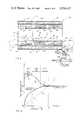
- FIG. 3is a plot of temperature and food temperatures within zones of such tunnel oven, as a function of cooking time.
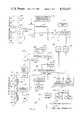
- FIG. 4is a schematic circuit diagram of control circuitry of the new tunnel oven.
- FIG. 5is a plan view of a control panel of the new oven.
- FIG. 6is a partially sectioned, simplified illustration of a modified version of a tier of the new oven.
- FIG. 7is a fragmentary end view of a further modification of the oven tier of FIG. 6.
- a pair of oven tiers, generally designated 10, 10'are positioned one atop the other, being both supported by a base generally referred to as 12 having longitudinal support members as at 14 bridging legs 16.
- a basegenerally referred to as 12 having longitudinal support members as at 14 bridging legs 16.
- rollers 18At the lower end of the legs are rollers 18 for readily allowing movement of oven A within desired premises, e.g., those of a commercial user engaged in fast food or industrial food service wherein partially prepared or frozen foods, such as pizza, casseroles, meat dishes, seafood and any of a myriad variety of foods are quickly heated for prompt serving upon the premises.
- oven Ahas application for other industrial and commercial usage, as well as domestic use if scaled down appropriately and in single tier configuration.
- Each of tiers 10, 10'includes a central oven portion 20 wherein there is included a horizontal tunnel-form cooking chamber, as shown representatively at 22 within upper tier 10'.
- An endless conveyor 24 as of mesh screened characterextends through the tunnel for conveying of products longitudinally therethrough to convey the products from an entrance at the right end of each tier as shown in FIG. 1 to an exit, as at 26, and for then depositing the cooked food products upon a delivery shelf 28 associated with each such tier.
- Structureas at 29, of suitable nature, interconnects each such central portion 20 with base 12, and such structure may include an upper surface or cover 30 separate from the oven tier central portion 20 for enclosing wiring and providing a suitable finished surface.
- Such cover or top 30may include as shown at one side a hinged access door 32 for permitting access to internal wiring of the oven, as for connection of AC power from power line mains, as for example, 440 volt three-phase service.
- Each such extension 34includes at its outer extremity a sloped control panel 35 including an alphanumeric display 38 for providing read-out of temperatures, operating conditions, and other parameters associated with operation.
- Panel 36includes also a push-button keyboard 40 by which the user may set, independently for each tier desired temperatures, cooking time, and other operating parameters, and other desired modes and conditions of operation, all of which will be provided and supervised automatically by microprocessor-controlled circuitry of the the invention.
- the pushbutton pad keyboard 40includes buttons not only with numerals but also appropriate legends.
- An on-off switch 42is also provided for each tier.
- a separate pushbutton 44permits the user to enter a desired operating condition, setting or the like, after selecting same by keyboard 40.
- a tunnel oven of the present charactermay as noted include but a single tier supported by base 12. Or the new oven may instead, have three or four tiers, or so-called decks, etc., each of which has its own separate control circuitry and control panel 36 for independent control of all functions provided by each such tier.
- Each tierincludes its own separate conveyor drive motor, or motors, which are housed in a rectangular extension 46 opposite the respective control circuitry extension 34 in the respective enclosure extension 46 is located the reduction gearing and other conventional drive components for the conveyor.
- An oven of the present characteris wholly electronic, utilizing heating elements of an electrically-energized nature to which the electrical power is controlled by circuits housed in the respective enclosure 34 of each tier.
- Section 20includes a horizontally exposed cooking tunnel 48, which may be most preferrably of rectangular cross section including a roof 50 and a floor generally designated 52 in the form of separate hearth panels or plate 54 which are joined end to end with but slight gaps 56 exaggerated in the drawing for purposes of illustration. Panels or plates together form a continuous longitudinal hearth or floor surface extending along the entire lengths of the tunnel 48.
- Said hearth plates 54are most preferably relatively thick steel in order to provide a thermal mass characteristically associated with such a hearth as utilized in the present type of tunnel oven wherein the internal surfaces, i.e., the hearth or floor 52 and roof 50 themselves are heated to predetermined temperatures for direct emission of infrared radiant energy for absorption of food products.
- Roof 50is also defined by individual panels or plates 58 but of much less thickness than plates 54, being similarly joined end to end with slight gaps as at 60, which are greatly exaggerated in the drawing for purposes of illustration, but with roof 50 seemingly continuous. Because of the separate nature of plates 54, 58, both hearth and roof are thus each divided into individual sections which may be maintained at different temperatures, and with the small gaps or discontinuities 56, 60 providing substantial thermal isolation as between the different sections whereby the different temperatures of the same are more readily maintained.
- IR heating unitsLocated beneath floor 52 are infrared emitters, herein termed IR heating units designated at 62 which are of panel-like configuration and lie closely beneath and proximate hearth plates 54. Although there is shown only one such IR heating unit 62 for each such plate 54, there may instead be a pair of such IR heaters for each such plate, as determined only by the desired ultimate length of the tunnel and by manufacturing considerations which may dictate preferred dimensions of each such unit 62. Similarly, IR units 64 are provided for each of roof panels or plates 58, being parallel to and closely proximate same. Again, for purposes of simplifying illustration, only one such unit 64 is shown for each plate 58. IR emitters utilized may be formed of the methodology and construction described and shown in co-assigned Wells U.S. Pat. No. 3,809,859.
- thermocouplesShown at 66, 68 are thermocouples which are illustrated as touching each of the respective hearth and roof plates 54, 58 to represent a condition of intimate thermal contact of each thermocouple with its respective plate and with its associated IR heating unit 62, 64 whereby the respective thermistor will be heated to precisely the same temperature as its associated respective hearth or roof panel.
- Said thermocouples 66, 68may most preferrably be part of a probe temperature sensing arrangement, as disclosed in co-assigned Wells et al U.S. Pat. No. 4,245,613 which illustrates also the preferred arrangement for obtaining intimate thermal relationship between the probe and respective roof or hearth heating surface.
- Conveyor return reach 24rpasses under heaters 62 for being kept hot.
- Oven unit or portion 20is also provided with thermal insulation 70, such as of layers of glass fiber for insulating the outer surfaces of unit 20 from the high temperatures developed internally by IR heating units 62, 64.
- thermal insulation 70such as of layers of glass fiber for insulating the outer surfaces of unit 20 from the high temperatures developed internally by IR heating units 62, 64.
- zones I, II, IIIthere are provided three heating zones I, II, III along the length of the oven.
- there may be different temperaturesallowing food products which are conveyed through the tunnel by conveyor 24 to be exposed to different temperatures in sequence as they pass successively through zones I, II, and III.
- the hearth and roof panels or plates 54, 58are separately heated, there is further developed if desired a vertical division of the zones into upper and lower portions.
- longitudinal zone IWhile it is a matter of arbitrariness to show definitively the demarcation between the upper and lower regions within each such longitudinal zone, and particularly since heating is substantially through only radiation from the hearth and roof surfaces, and accordingly not by heated forced or convective air, there has shown within longitudinal zone I been merely for purposes of graphic illustration an upper vertical zone u and lower vertical zone portion 1.
- a food product upon conveyor 24will be exposed on its top surface to the temperature associated with plate 58 in the respective zone while its bottom surface will be exposed to the temperature associated with the hearth plate 54 in such zone.
- Conveyor 24is as noted of continuous chain-belt configuration, being passed around opposite end rollers 72, 74.
- An idler roller 76provides tensioning of the belt, which may be of steel or stainless steel and of a link or mesh character.
- Roller 74is a drive roller, being driven through a belt 78 by a DC motor M1.
- the motoris of controllable speed type, being driven by digital circuitry of the invention at a precisely controlled speed for causing conveyor 24 to travel at such a precisely controlled speed that the food products are conveyed through tunnel 48 within a correspondingly precise time as preselected by the user. Control of the speed of motor M1 thereby provides also for precise control over the length of time during which such a food product will traverse the length of any one of zones I, II, and III.
- the motor shaftincludes a wheel 80 carrying a small permanent magnet 82 by means of which a sensor S1 operates to sense each rotation of wheel 80.
- Sensor S1is accordingly most preferably of the Hall-effect type, being also connected with the control circuitry of oven tier or unit 20.
- motor M2is also connected with the control circuitry, as is also a Hall-effect sensor S2 for sensing the speed of rotation of motor M2. If only a single conveyor 24 is used, motor M2 is not needed and may not be present, but its presence in FIG. 2 demonstrates the manner of its connection with the control circuitry described hereinbelow.
- control circuitry of the inventionis designated in its entirety generally by reference numeral 100.
- Such circuitryincludes a microprocessor 102 of conventional 8-bit configuration such as commercially available type 6802.
- Microprocessor 102provides supervisory control and execution of all functions of the circuitry, including energization of the IR heaters or units 62, 64, monitoring of thermocouples 66, 68 and driving of motor M1 (and motor M2, if used) all as provided by user inputs from keypad 40.
- the latteris connected to a conventional matrix decoder 104 for providing conventional decoding of the keypad input and providing same as conventional BCD data to a data bus 106 which is interconnected with the microprocessor.
- data upon data bus 106is provided to address latches 108 according to addressed provided upon data bus 106 by microprocessor 102.
- Such conventional latches 108supply signals to electronic switching devices such as triacs 110 which control the switching of utility service AC power to the IR heaters or units 62, 64.
- the actual number of such drivers 110is dependent upon the number of heaters 62, 64.
- a speaker or other transducer 112(such as of piezoelectric type) for providing audible signals such as preferably tones or beeps when driven through a driver 114 such as a power transistor when appropriately addressed by data on bus 106.
- a driver 114such as a power transistor when appropriately addressed by data on bus 106.
- Transducer 112can also be used for signalling the end of a cooking interval, a fault, or other condition to which the user should be alerted.
- Data of bus 106is also provided to a pair of data-to-pulsewidth converters 116, 116' which are of conventional commercially integrated circuit type configured suitably for converting the data on bus 106, as appropriately addressed for each of motors M1, M2, to provide a pulse-form signal having thereby a data-selected pulsewidth.
- the pulse-form signalis supplied via drivers 118, 118' such as power transistors, to motors M1 and M2.
- the motor speedcan be precisely controlled causing products to be conveyed through the tunnel within a predetermined time interval and, thus also, through each zone I, II and III in a correspondingly shorter predetermined time interval.
- sensors S1 and S2provide signals through buffers 120, 120" to appropriate logic gates 122 of integrated circuit configuration.
- Such speed data on data bus 106is made available to microprocessor 102, which is programmed to vary the pulsewidth accordingly by the use of a resident program contained within an electrically programmable read only memory (EPROM) 124 which is addressed by microprocessor 102 and provides signals by way of a bus extension 106'.
- EPROMelectrically programmable read only memory
- RAMrandom access memory
- microprocessorfor storing the data utilized during execution of the program such as, for example, sensed temperatures, sensed motor speed, and the like.
- Data so stored in RAM 126is inavailable by a bus extension 106" to microprocessor 102.
- Shown at 130is a real-time clock circuit preferrably in the form of an integrated circuit chip having an internal random access memory (RAM) 132 for retaining the clock and any other desired data, for access to same via data bus 106 by operation of microprocessor 102.
- a back-up battery 134is preferably used for maintaining power for clock chip 130 and its internal RAM 132 in the case of a power outage or disconnection.
- Clock 130by operation of microprocessor 102 and keypad 40, is utilized for providing time-of-day and for permitting microprocessor initiated actions of all desired functions at time-of-day settings provided via keypad 40, as desired by the user.
- the new ovencan be turned on automatically under control of microprocessor 102 at a present time of day.
- Display 38is preferrably of the liquid crystal type (LCD) and is driven by a conventional integrated circuit interface 136 from data bus 106.
- LCDliquid crystal type
- the instruction set of EPROM 124 for microprocessor 102includes display by LCD display 38 of oven status, as when on or off; for signifying heating up to a preselected temperature; values of the actual temperatures within each of zones I, II and III, for both the bottom and the top radiating surfaces; various times, temperatures and other parameters set in by use of keypad 40; as well as various warning functions, such as overtemperatures or undertemperatures conditions or failure of components such as heating elements, jamming of the motor, loss of stored data in memory, and so forth.
- thermocouples 68, 66are monitored by microprocessor 102.
- thermocouples 68, 66interconnect with respective differential amplifiers of integrated circuit type, as designated at 138, 140.
- the differential amplifiersaccordingly provide analog signal voltages to a conventional integrated circuit multiplexer 142 controlled by data input 144 from microprocessor 102 in the form of 12-line addresses delivered through conventional integrated circuit two-directional gates 146.
- Multiplexer 142thus develops a series of analog signals proportional to the temperature sensed by each of thermocouples 68, 66 according to the address provided on input 144, and such signals are provided by a lead 148 to an analog-to-digital (A/D) converter 150.
- A/Danalog-to-digital
- a voltage referenceis provided by a regulated circuit 152 for operation of A/D converter 150.
- Addressing for the A/D converter 150is supplied by an address input 152 from the two-directional gates 146.
- Binary coded decimal (BCD)is accordingly provided from A/D converter 150 by a four line control connection 154 through two-directional gates 156 of conventional integrated circuit character and thus made available to data bus 106 for storage and comparison by microprocessor 102 with data provided in RAM 126 and EPROM 124.
- EPROM 124preferably is provided with a look-up table or tables by conventional programming for establishing appropriate temperature heating and cooling curves which will have been found appropriate for preventing overshoot upon energization of the respective IR heaters 62, 64 if heating is required to increase zone temperatures to pre-selected values and for permitting similarly an appropriate cooling down upper zone temperatures exceeding pre-selected values.
- thermocouple compensation circuit 158may most preferably comprise a solid state temperature controller such as type LM135 which is biased with a zener-regulated voltage. It is preferred that such temperature controller of circuit 158 be located near the point of connections of thermocouples 68, 66 in order to provide a temperature-compensated voltage reference to multiplexer 142 so that the signal provided on line 148 corresponding to the respective thermocouple address will be referenced to room temperature, such otherwise there could result in error in the temperature sensed by thermocouples 58, 66. In operation of circuit 158 the signal from circuit 158 then constitutes a room temperature which digitally may be added to the absolute temperature sensed by each of thermocouples 58, 66.
- microprocessor 102is caused to carry out a sequence of first sampling the temperatures measured by thermocouples 58, 66, the microprocessor then measuring the difference in temperatures (dT) between the beginning and end of the sampling interval (dt). Microprocessor 102 is then utilized to calculate in effect the slope (dT/dt) thereby determined. The microprocessor then compares such slope with the data of the look-up tables of EPROM 124 for the purpose of turning on or off the respective IR heater 62, 64 depending upon such comparison.
- the sampling intervalis most preferably about 3-4 seconds, but most broadly preferred to be within the range of 2-10 seconds. Programming of the microprocessor for these purposes will be within the skill of programmers familiar with type 6802. Thus, the microprocessor provides addressed heating signals to latches 108 for proportioned heater energizing during the sampling interval.
- motor speedis then if necessary increased or decreased by corresponding change in the data made available to converters 116, 116' which thereby control the pulse-width of the pulse-form signals provided to the motors.
- motor speedis data-correlated to a given interval of time for a food product to traverse the entire length of the tunnel or any of zones I, II or III, as measured in minutes and seconds of cooking time.
- EPROM 124may be programmed to provide for profiled changes in the speed of conveyor 24 to provide thereby programming of different speeds of the conveyor for different food products as they traverse to different zones.
- circuit 100thereby provides the functions of temperatures control in the several zones of the tunnel oven and coordinated control of the conveyor speed to provide conveying of products through the tunnel and its several zones within a preselected cooking time.
- the inventionmakes possible a profiling of the cooking of any type of food product by the use of different temperatures in the different zones.
- zones I, II and IIIdifferent temperatures T 1 , T 2 and T 3 are shown, all of which are above a cooking range extending between a lower value T a and higher value T b appropriate for a food product to be cooked.
- the food productmay, for example, be frozen when introduced into the tunnel and at initial temperature T 0 .
- a typically linear function F 1may typify the actual temperature of the product as it travels through a tunnel in the course of a cooking time interval t f -t o and requiring a substantially high temperature within the oven to achieve a final temperature T b .
- a cooking function F 2results wherein the high temperature T 1 brings the food product up to the beginning temperature T a at a much earlier time t 1 .
- Cookingthen increases along curve F 2 throughout zone II until time t 2 at which point the food product enters zone III in which a greatly reduced temperature T 3 is maintained such as will permit finishing of the cooking of the food product wherein its temperature asymptotically approaches the finished cooking temperature T b as the oven emerges at time t f .
- zone Imay be thought of as a bring-up zone for initially increasing the temperature of the food product very quickly to permit cooking to be initiated within the cooking range much earlier (at time t 1 ) than would occur with a conventional oven. It is seen, therefore, that cooking of food products by the use of different temperature zones permits a vast reduction in the amount of time required for cooking of the food product.
- a conventional ovenIn the case of a conventional oven, it is seen that cooking is not even initiated until a time t 3 and such would require maintenance of the food product within a cooking tunnel for longer than when using the present oven. In addition, it is apparent that a linear extrapolation F' 1 results if the food product is maintained within the tunnel oven for a time greater than t f . Accordingly, a conventional oven may require the use of an even lower temperature than assumed for curve F 1 if an over-temperature exposure of the food product is to be avoided, thus even further lengthening cooking interval. If, in order to prevent such overshoot or excessive temperature, a much lower conventional cooking temperature were used, the food product may not cook at all.
- gelatinizationIn cooking of some products, for example, gelatinization must occur such as between 160° and 180° F. Attempted cooking at less than 140° F. will not produce such gelatinization so that the product is not at all cooked, even when so heated for hours.
- the new ovenentirely avoids such difficulties, allowing a cooking profile unique to each type of food product to be established and used during cooking. In net effect, food products are rapidly, accurately and uniformally cooked by the new oven by being differentially heated in the different zones, producing a novel and extremely advantageous profiled cooking of the food products as they are conveyed through the different zones in a precisely time-controlled manner.
- the ovencan be programmed to turn on automatically at a given time of day and to maintain only a stand-by temperature, which will conserve electricity, until user initiation of cooking is entered by keypad 40. Then, temperature control automatically brings the temperatures in each zone to preselected values, as established by the user in advance by keypad entry. Also, the oven can be programmed to turn off or to return to its stand-by mode at a given time. Additionally, the oven is readily programmed for causing microprocessor 102 to sequentially, if desired, turn on oven heater units to avoid exceeding a predetermined peak current demand which, if exceeded, would cause the user to incur excess electric power charges.
- an oven of the present configurationalso can be caused to enter a self-cleaning mode wherein the internal temperatures are sufficiently great, e.g., up to nearly 1000° F., that food particles will be carbonized. Normally, however, temperatures for cooking within the different zones may be broadly within the range of 200°-900° F.
- the usermay by use of keypad 40 interrogate the circuitry to ascertain the temperatures at the top and bottom of any of the zones and monitor all aspects of the operations.
- Self-diagnostic capabilityis also inherent within the circuitry since microprocessor 102 can be programmed to monitor various conditions, such as motor overspeed, underspeed, stall, overtemperature conditions, or the like, to which the user should be alerted.
- a modified tier 200 of the new ovenincludes a center portion 220 having a widened tunnel-form cooking chamber 222 through which extend two conveyors 224l, 224r which are independently driven by motors M1, M2 (see FIG. 2) in side-by-side relation. Delivery or serving shelves 228l, 228r are associated with the two conveyors.
- a control extension 234contains control circuitry and presents a sloping panel 236 on which are provided a display 238 and keypad 240 of the previously described character for display and entry respectively, of data such as temperatures and cooking times for both the left and right halves of tunnel 222.
- a motor and conveyor drive housing extensionmay be provided but, for simplicity, is not shown.
- conveyor 224lExtending longitudinally as a hearth 252 below conveyor 224l are separate hearth plates 254 below which are respective IR heater units 262 and thermocouple sensor probes 266. Similar separate hearth plates and IR heating units, etc. (not shown), extended beneath conveyor 224r. Above conveyor 224l is a roof 250 having separate roof plates 258 over which are respective IR heater units 264, as well as thermocouple probes 268 for direct temperature sensing as above described.
- each such zonemay be further vertically divided into upper and lower portions.
- Oven tier 200may be used in a multiple-tier oven according to the previously described general configuration to provide a stacking of tiers which are each independent. However, more importantly, each such tier 200 is, in effect, two side-by-side tunnel halves albeit forming one tunnel. In each half of the tunnel, cooking time for food products may be different by reason of the conveyors 224l, 224r travelling at different speeds. Upper and lower cooking temperatures (IR emission) within each of three longitudinal zones of each half of the tunnel may be separately maintained.
- Microprocessor circuitry of FIG. 4is preferably utilized and its capabilities are such that a single keypad 240 and display 238 are adequate for user selection and monitoring of the various temperatures, cooking times and other parameters associated with each of the left and right tunnel halves.
- control panel 236may be provided with separate keypads and displays for the two halves of the oven.
- a modified tier 300includes a widened tunnel 322 like tunnel 222 and having a left portion 322l and right portion 322r.
- a single conveyor 324extends longitudinally through tunnel 322 for delivery of food products to a delivery shelf or station 328, being delivered accordingly by a single motor of the type disclosed above.
- the tunnel halves 322l and 322rmay each have separate hearth plates and hearth heaters of the IR type as above disclosed, as well as separate roof panels and separate IR heating units for such roof panels to provide multiple longitudinal zoning within each of the two halves. Food products thereby travel through each of the two tunnel halves with the same cooking time. However, different temperatures can be maintained laterally within each of the longitudinal zones of tunnel 322.
- a barrier 331is shown extending from the roof of tunnel 322 to a point near the upper surface of conveyor 324.
- Barrier 331extends the full length of the tunnel 322 and may be of metal or other temperature-resistant material such as will enhance the maintaining of separate temperatures on opposite sides of such barrier 331.
- Barrier 331may be secured by suitable means such as by having an enlarged portion or rail 333 at its upper edge fitted between L-shaped brackets 335, 335' carried along the length of the tunnel roof. The barrier may accordingly be readily removed, if not needed or to permit food products of wide extent to be conveyed.
- Operation of the new ovenis seen to provide an advantageous method of tunnel oven cooking of food products.
- the methodthus includes heating interior surfaces within the tunnel to provide at least two different zones extending longitudinally along the tunnel, and maintaining different hearth and roof emission temperatures within the different zones according to a desired heating profile for the products.
- profiled cooking of the food productsis obtained.
- the roof and hearth temperatures in the first zoneare maintained sufficiently great for bringing up the food products to cooking temperature, while the roof and hearth temperatures in the second zone are maintained at temperatures less than in the first zone but sufficiently great for actual cooking of the food products.
- a third different zonecan also be provided wherein still lower hearth and roof temperatures are maintained but sufficiently great for finishing the food products.
Landscapes
- Engineering & Computer Science (AREA)
- Mechanical Engineering (AREA)
- General Engineering & Computer Science (AREA)
- Life Sciences & Earth Sciences (AREA)
- Food Science & Technology (AREA)
- Chemical & Material Sciences (AREA)
- Combustion & Propulsion (AREA)
- Electric Stoves And Ranges (AREA)
Abstract
Description
Claims (15)
Priority Applications (2)
| Application Number | Priority Date | Filing Date | Title |
|---|---|---|---|
| US06/611,108US4554437A (en) | 1984-05-17 | 1984-05-17 | Tunnel oven |
| US06/778,350US4664923A (en) | 1984-05-17 | 1985-10-24 | Method of infrared tunnel oven cooking of food products |
Applications Claiming Priority (1)
| Application Number | Priority Date | Filing Date | Title |
|---|---|---|---|
| US06/611,108US4554437A (en) | 1984-05-17 | 1984-05-17 | Tunnel oven |
Related Child Applications (1)
| Application Number | Title | Priority Date | Filing Date |
|---|---|---|---|
| US06/778,350DivisionUS4664923A (en) | 1984-05-17 | 1985-10-24 | Method of infrared tunnel oven cooking of food products |
Publications (1)
| Publication Number | Publication Date |
|---|---|
| US4554437Atrue US4554437A (en) | 1985-11-19 |
Family
ID=24447658
Family Applications (1)
| Application Number | Title | Priority Date | Filing Date |
|---|---|---|---|
| US06/611,108Expired - LifetimeUS4554437A (en) | 1984-05-17 | 1984-05-17 | Tunnel oven |
Country Status (1)
| Country | Link |
|---|---|
| US (1) | US4554437A (en) |
Cited By (115)
| Publication number | Priority date | Publication date | Assignee | Title |
|---|---|---|---|---|
| US4711164A (en)* | 1985-04-19 | 1987-12-08 | Mendoza Fausto C | Oven for preparing fried food products |
| GB2198825A (en)* | 1986-12-17 | 1988-06-22 | Meltech Eng | Furnace for continuously heat treating wire |
| US4881519A (en)* | 1988-07-18 | 1989-11-21 | Lincoln Foodservice Products, Inc. | Hot air oven having infra-red radiant surfaces |
| US4886954A (en)* | 1988-04-15 | 1989-12-12 | Thermco Systems, Inc. | Hot wall diffusion furnace and method for operating the furnace |
| EP0346117A1 (en)* | 1988-06-08 | 1989-12-13 | Electrovert Ltd. | Improved heating system in the manufacture of printed circuit boards, assemblies and the like |
| US4924714A (en)* | 1987-04-29 | 1990-05-15 | Hoechst Aktiengesellschaft | Apparatus for the transport of partially temperature-controlled test material in strip form |
| US4951648A (en)* | 1989-03-23 | 1990-08-28 | Tecogen, Inc. | Conveyor oven |
| US4956530A (en)* | 1988-09-10 | 1990-09-11 | Hermann Berstorff Maschinenbau Gmbh | Method of operation and device for even heating by means of microwaves |
| US4956532A (en)* | 1988-10-11 | 1990-09-11 | Hermann Berstorff Maschinenbau Gmbh | Method and apparatus for even heating of products by means of microwaves |
| EP0395149A1 (en)* | 1989-04-19 | 1990-10-31 | Interuniversitair Microelektronica Centrum Vzw | Method and device for accelerated determining of ageing of one or more elements with an electromagnetic ageing parameter |
| US5036179A (en)* | 1988-05-19 | 1991-07-30 | Quadlux, Inc. | Visible light and infra-red cooking apparatus |
| US5039535A (en)* | 1988-01-14 | 1991-08-13 | Lang Manufacturing Company | Method of cooking food products |
| US5083010A (en)* | 1990-05-31 | 1992-01-21 | Bosch-Siemens Hausgerate Gmbh | Pyrolytic self-cleaning stove |
| US5154160A (en)* | 1991-05-12 | 1992-10-13 | Q Industries Food Equipment Co. | Automated oven with gas-fired radiant heater assembly |
| US5167078A (en)* | 1991-10-24 | 1992-12-01 | International Business Machines Corporation | Compact photo resist dryer |
| US5180096A (en)* | 1990-07-25 | 1993-01-19 | Nihon Den-Netsu Keiki Co., Ltd. | Method and apparatus for reflow-soldering of printed circuit boards |
| US5180898A (en)* | 1991-07-25 | 1993-01-19 | G. S. Blodgett Corporation | High velocity conveyor oven |
| US5182439A (en)* | 1991-08-19 | 1993-01-26 | Henny Penny Corporation | Method and apparatus for operating a food oven |
| US5197375A (en)* | 1991-08-30 | 1993-03-30 | The Middleby Corporation | Conveyor oven control |
| EP0541353A1 (en)* | 1991-11-05 | 1993-05-12 | Bgk Finishing Systems, Inc. | Method and apparatus for heat treating of aluminium or an aluminium alloy |
| US5223290A (en)* | 1991-08-13 | 1993-06-29 | G. S. Blodgett Corporation | Method for cooking food in an infra-red conveyor oven |
| US5228114A (en)* | 1990-10-30 | 1993-07-13 | Tokyo Electron Sagami Limited | Heat-treating apparatus with batch scheme having improved heat controlling capability |
| US5235158A (en)* | 1990-08-01 | 1993-08-10 | Centro Sviluppo Materiali Spa | Device for continuous production of ceramic superconductor |
| US5253564A (en)* | 1991-08-30 | 1993-10-19 | The Middleby Corporation | Conveyor oven control |
| US5291514A (en)* | 1991-07-15 | 1994-03-01 | International Business Machines Corporation | Heater autotone control apparatus and method |
| US5414244A (en)* | 1993-04-21 | 1995-05-09 | Tokyo Electron Limited | Semiconductor wafer heat treatment apparatus |
| US5421723A (en)* | 1994-03-25 | 1995-06-06 | International Business Machines Corporation | Sequential step belt furnace with individual concentric cooling elements |
| US5471033A (en)* | 1994-04-15 | 1995-11-28 | International Business Machines Corporation | Process and apparatus for contamination-free processing of semiconductor parts |
| US5478986A (en)* | 1988-05-19 | 1995-12-26 | Quadlux, Inc. | Method and apparatus for making popcorn using electron and molecular excitation mode |
| US5517005A (en)* | 1988-05-19 | 1996-05-14 | Quadlux, Inc. | Visible light and infra-red cooking apparatus |
| US5522308A (en)* | 1993-09-29 | 1996-06-04 | Matsushita Electric Industrial Co., Ltd. | Griddle |
| US5528018A (en)* | 1991-08-19 | 1996-06-18 | Henny Penny Corporation | Programmable load compensation method and apparatus for use in a food |
| US5534679A (en)* | 1994-05-20 | 1996-07-09 | Quadlux, Inc. | Apparatus for automated food handling |
| US5620624A (en)* | 1988-05-19 | 1997-04-15 | Quadlux, Inc. | Cooking method and apparatus controlling cooking cycle |
| US5646540A (en)* | 1989-04-19 | 1997-07-08 | Interuniversitair Micro-Elektronic Centrum Vzw | Apparatus and method for measuring electromagnetic ageing parameter of a circuit element and predicting its values |
| US5665259A (en)* | 1988-05-19 | 1997-09-09 | Quadlux, Inc. | Method of cooking food in a lightwave oven using visible light without vaporizing all surface water on the food |
| US5686004A (en)* | 1996-04-29 | 1997-11-11 | Schneider; Russell C. | Pizza oven with conveyor |
| US5688422A (en)* | 1995-04-28 | 1997-11-18 | Henny Penny Corporation | Programmable fan control method and apparatus for use in a food oven |
| US5726423A (en)* | 1988-05-19 | 1998-03-10 | Quadlux, Inc. | Apparatus and method for regulating cooking time in a radiant energy oven |
| US5821503A (en)* | 1997-07-23 | 1998-10-13 | Hatco Corporation | Conveyor speed control ciruit for a conveyor oven |
| US5832812A (en)* | 1997-02-25 | 1998-11-10 | Wolfe; Ronald Dale | Dual conveyer oven |
| US5857847A (en)* | 1997-04-17 | 1999-01-12 | Chrysler Corporation | Brazing furnace parts feeding control |
| US5868564A (en)* | 1992-07-28 | 1999-02-09 | International Business Machines Corporation | Sequential step belt furnace with individual concentric heating elements |
| US5883362A (en)* | 1988-05-19 | 1999-03-16 | Quadlux, Inc. | Apparatus and method for regulating cooking time in a lightwave oven |
| US5906485A (en)* | 1998-02-27 | 1999-05-25 | Reading Pretzel Machinery Corporation | Tunnel-type conveyor oven having two types of heat sources |
| WO1999030565A1 (en)* | 1997-12-17 | 1999-06-24 | Quadlux, Inc. | Lightwave oven having automatic food conveyor |
| US5934357A (en)* | 1996-11-13 | 1999-08-10 | Aluminum Company Of America | System for manufacturing metal matrix composites |
| US5954980A (en)* | 1988-05-19 | 1999-09-21 | Quadlux, Inc. | Apparatus and method for uniformly cooking food with asymmetrically placed radiant energy sources |
| US5958271A (en)* | 1997-09-23 | 1999-09-28 | Quadlux, Inc. | Lightwave oven and method of cooking therewith with cookware reflectivity compensation |
| US5990454A (en)* | 1997-09-23 | 1999-11-23 | Quadlux, Inc. | Lightwave oven and method of cooking therewith having multiple cook modes and sequential lamp operation |
| US6011242A (en)* | 1993-11-01 | 2000-01-04 | Quadlux, Inc. | Method and apparatus of cooking food in a lightwave oven |
| US6013900A (en)* | 1997-09-23 | 2000-01-11 | Quadlux, Inc. | High efficiency lightwave oven |
| US6157002A (en)* | 1998-02-06 | 2000-12-05 | Middleby Cooking Systems Group | Small conveyor toaster/oven |
| US6288366B1 (en)* | 1998-12-17 | 2001-09-11 | Otb Group B.V. | Furnace for the production of solar cells |
| US6313444B1 (en)* | 1999-08-24 | 2001-11-06 | C. A. Litzler Co., Inc. | Radiant oven |
| US20010041357A1 (en)* | 1999-07-28 | 2001-11-15 | Yves Fouillet | Method for carrying out a biochemical protocol in continuous flow in a microreactor |
| US6526961B1 (en) | 2000-07-10 | 2003-03-04 | Lincoln Foodservice Products, Inc | Conveyor oven |
| US6559425B2 (en)* | 1999-09-03 | 2003-05-06 | Alliedsignal Bremsbelag Gmbh | Method and a device for the thermal treatment of friction lining surfaces |
| US6624396B2 (en)* | 2001-08-28 | 2003-09-23 | Hatco Corporation | Conveyor speed control system for a conveyor oven |
| US6707014B1 (en)* | 2001-01-05 | 2004-03-16 | Dave O. Corey | Oven apparatus for efficiently cooking food |
| US6780448B1 (en)* | 2001-02-06 | 2004-08-24 | David Howard | Pasteurization of food products |
| US6867392B1 (en) | 2004-01-23 | 2005-03-15 | David Howard | Infrared element and oven |
| US6866417B2 (en) | 2002-08-05 | 2005-03-15 | Fmc Technologies, Inc. | Automatically measuring the temperature of food |
| US20050205547A1 (en)* | 2004-03-22 | 2005-09-22 | Hatco Corporation | Conveyor oven |
| US20050236385A1 (en)* | 2004-04-02 | 2005-10-27 | American Permanent Ware Corporation | Conveyor type oven |
| US20050242077A1 (en)* | 2004-04-28 | 2005-11-03 | Q-Matic Technologies, Inc. | Food preparation oven having quartz heaters |
| WO2005112650A1 (en)* | 2003-02-21 | 2005-12-01 | Middleby Corporation | Charbroiler |
| US7007807B1 (en) | 2003-01-29 | 2006-03-07 | Fmc Technologies, Inc. | Sorting system for multiple conveyor belts |
| US7038172B1 (en) | 2003-05-16 | 2006-05-02 | Marshall Air Systems, Inc. | Conveyorized food broiling apparatus |
| US20060096480A1 (en)* | 2004-09-25 | 2006-05-11 | Techno-Graphica Gmbh | Device for heat-treating a coating of flat-bed offset printing plates |
| US20060157469A1 (en)* | 2005-01-19 | 2006-07-20 | Coleman Marshall K | Radiant cooking oven |
| US20060174508A1 (en)* | 2005-02-04 | 2006-08-10 | Govek Jeffrey P | Computer to plate curing system |
| US20060177760A1 (en)* | 2005-02-04 | 2006-08-10 | Printing Research, Inc. | Computer to plate color sensor and drying/curing system and method |
| US20070012307A1 (en)* | 2004-03-23 | 2007-01-18 | Middleby Corporation | Conveyor oven apparatus and method |
| US20070084849A1 (en)* | 2005-10-05 | 2007-04-19 | General Electric Company | Systems and methods for controlling oven cooking |
| US7285299B1 (en) | 2002-02-22 | 2007-10-23 | David Howard | Surface pasteurization of cooked food products |
| US7323663B2 (en) | 2004-02-10 | 2008-01-29 | Applica Consumer Products, Inc. | Multi-purpose oven using infrared heating for reduced cooking time |
| US20080044167A1 (en)* | 2003-12-18 | 2008-02-21 | Luis Cavada | Method for toasting a food product with infrared radiant heat |
| US7340992B1 (en)* | 2005-01-27 | 2008-03-11 | Wolfe Electric, Inc. | Dual belt conveyor oven |
| US20080267750A1 (en)* | 2007-04-30 | 2008-10-30 | Bramhall Marcus E | Methods for moving ovens, and ovens having means for releasably attaching to a plurality of casters |
| US20090034944A1 (en)* | 2007-07-30 | 2009-02-05 | Burtea Sanda | Conveyor oven with multiple heating zones |
| EP2022333A1 (en)* | 2007-08-08 | 2009-02-11 | Michele Pignata | Tunnel oven for foodstuffs, particularly baked products, such as pizzas, focaccia bread and the like |
| US20090110794A1 (en)* | 2005-07-08 | 2009-04-30 | Proval Beheer B.V. | Device and Method for Heating Food Products |
| US20090175988A1 (en)* | 2008-01-03 | 2009-07-09 | Iet Combustion Llc | Oven |
| US20090173599A1 (en)* | 2008-01-03 | 2009-07-09 | Iet Combustion Llc | System and Method for Product Removal |
| US20090223503A1 (en)* | 2003-02-21 | 2009-09-10 | Wiker John H | Self-cleaning oven |
| US20090263758A1 (en)* | 2008-04-17 | 2009-10-22 | Eva Schwartz | Method and continuous furnace for heating workpieces |
| US7619186B2 (en) | 2004-02-10 | 2009-11-17 | Applica Consumer Products, Inc. | Intelligent user interface for multi-purpose oven using infrared heating for reduced cooking time |
| US20110048245A1 (en)* | 2009-08-28 | 2011-03-03 | Schjerven Sr William S | Apparatus and method for controlling a conveyor oven |
| EP2131119A3 (en)* | 2008-06-06 | 2012-10-17 | Iber Emec, S.A. | Tactile control unit for electrical heat emitters |
| WO2012145500A1 (en)* | 2011-04-19 | 2012-10-26 | Owens Corning Intellectual Capital, Llc | Apparatus and method for cure monitoring and process control in glass fiber forming operation |
| US20130143172A1 (en)* | 2011-12-02 | 2013-06-06 | Wildcat Discovery Technologies, Inc. | High throughput furnace |
| US8637792B2 (en) | 2011-05-18 | 2014-01-28 | Prince Castle, LLC | Conveyor oven with adjustable air vents |
| US8718969B2 (en) | 2011-04-19 | 2014-05-06 | Owens Corning Intellectual Capital, Llc | Apparatus and method for continuous thermal monitoring of cure status of glass fiber products |
| US20140199446A1 (en)* | 2013-01-11 | 2014-07-17 | Star Manufacturing International, Inc. | Split-Belt Conveyor Toaster |
| US20140318382A1 (en)* | 2010-05-11 | 2014-10-30 | Standex International Corporation | Quick heating quartz toaster |
| US20140352550A1 (en)* | 2011-05-11 | 2014-12-04 | Haas Food Equipment Gmbh | Baking oven comprising a continuous baking belt |
| US8952298B2 (en) | 2009-06-12 | 2015-02-10 | Burger King Corporation | Electric broiler |
| CN104430667A (en)* | 2014-10-23 | 2015-03-25 | 丽水市炉麦烧餐饮管理有限公司 | Clay oven roll baking machine |
| US9128048B2 (en) | 2010-12-09 | 2015-09-08 | Owens Corning Intellectual Capital, Llc | Method for online determination of cure status of glass fiber products |
| US20150292749A1 (en)* | 2014-04-14 | 2015-10-15 | Samsung Electronics Co., Ltd. | Oven and method for controlling the same |
| US9585400B2 (en) | 2004-03-23 | 2017-03-07 | The Middleby Corporation | Conveyor oven apparatus and method |
| US20180073805A1 (en)* | 2016-09-13 | 2018-03-15 | M&R Printing Equipment, Inc. | Multiple Belt and Multiple Zone Textile Dryer |
| US10004358B2 (en) | 2012-05-16 | 2018-06-26 | Hatco Corporation | Toaster with controlled conveyor speed |
| CN108463147A (en)* | 2015-10-13 | 2018-08-28 | D·帕特尔 | Conveyor barbecue appliance for cooking or reheating food |
| US10398148B2 (en) | 2008-01-03 | 2019-09-03 | Souhel Khanania | Oven |
| US20200090965A1 (en)* | 2018-09-14 | 2020-03-19 | Kokusai Electric Corporation | Substrate processing apparatus and manufacturing method of semiconductor device |
| US10612850B2 (en) | 2015-08-31 | 2020-04-07 | M&R Printing Equipment, Inc. | System and method for dynamically adjusting dryer belt speed |
| US11045047B2 (en) | 2017-11-10 | 2021-06-29 | Ron's Enterprises, Inc. | Variable capacity oven |
| RU206264U1 (en)* | 2021-05-14 | 2021-09-02 | Непубличное акционерное общество "Шебекинский машиностроительный завод" | Conveyor oven with infrared heating for baking flour confectionery |
| US11266152B2 (en)* | 2016-03-09 | 2022-03-08 | Dmp Enterprises Pty Ltd | Conveyer-type oven |
| US20220395139A1 (en)* | 2021-06-15 | 2022-12-15 | Jiangmen City Xinhui Henglong Innovative Housewares Co., Ltd. | Toaster |
| US11558933B2 (en)* | 2018-03-08 | 2023-01-17 | Watlow Electric Manufacturing Company | Control system for controlling a heater |
| US12053010B2 (en) | 2018-04-23 | 2024-08-06 | Rylans Enterprises Llc | Chile roaster |
| EP4593526A1 (en)* | 2024-01-23 | 2025-07-30 | The Middleby Corporation | Control methods for infrared conveyor ovens |
Citations (18)
| Publication number | Priority date | Publication date | Assignee | Title |
|---|---|---|---|---|
| US2146427A (en)* | 1936-11-28 | 1939-02-07 | Nat Biscuit Co | Oven |
| US2629162A (en)* | 1949-10-27 | 1953-02-24 | Palatine Dyeing Company Inc | Method and apparatus for heattreating textile fabrics |
| US2872173A (en)* | 1949-12-12 | 1959-02-03 | Munker Theo | Method and apparatus for heat treating materials in a continuous operating furance |
| US3471682A (en)* | 1968-02-07 | 1969-10-07 | Armstrong Cork Co | Radiant heating apparatus |
| US3496133A (en)* | 1965-05-10 | 1970-02-17 | Du Pont | Process for preparing filled polymeric structures |
| US3585390A (en)* | 1968-02-07 | 1971-06-15 | Tadashi Ishikawa | Zirconia ceramics and infrared ray radiation elements utilizing the same |
| US3721805A (en)* | 1971-02-11 | 1973-03-20 | Simon Vicars Ltd | Oven control |
| US3842794A (en)* | 1973-06-29 | 1974-10-22 | Ibm | Apparatus for high temperature semiconductor processing |
| US3956612A (en)* | 1974-10-04 | 1976-05-11 | Irex Corporation | Radiant heating modular unit |
| WO1979000663A1 (en)* | 1978-02-27 | 1979-09-06 | R Stuck | Cooking apparatus |
| DE3020276A1 (en)* | 1979-06-07 | 1980-12-11 | Hans Andersson | Rotary direction monitor for dry centrifuges etc. - has permanent magnet(s) on rotary carrier facing two Hall elements, each in logic signal generator |
| US4245613A (en)* | 1978-11-01 | 1981-01-20 | Black Body Corporation | Tunnel oven |
| US4276603A (en)* | 1979-10-30 | 1981-06-30 | Btu Engineering Corporation | Diffusion furnace microcontroller |
| US4333002A (en)* | 1980-09-02 | 1982-06-01 | A. O. Smith Corporation | Multiple device control apparatus |
| CA1140659A (en)* | 1979-08-27 | 1983-02-01 | Brent A. Beatty | High temperature heat controller with zero-crossing switch |
| US4376915A (en)* | 1981-03-30 | 1983-03-15 | Dart Controls, Inc. | Tachometer |
| US4389562A (en)* | 1981-08-05 | 1983-06-21 | Hatco Corporation | Conveyor oven |
| US4441077A (en)* | 1981-11-23 | 1984-04-03 | International Business Machines | Real time eddy current responsive Hall effect device tachometer |
- 1984
- 1984-05-17USUS06/611,108patent/US4554437A/ennot_activeExpired - Lifetime
Patent Citations (18)
| Publication number | Priority date | Publication date | Assignee | Title |
|---|---|---|---|---|
| US2146427A (en)* | 1936-11-28 | 1939-02-07 | Nat Biscuit Co | Oven |
| US2629162A (en)* | 1949-10-27 | 1953-02-24 | Palatine Dyeing Company Inc | Method and apparatus for heattreating textile fabrics |
| US2872173A (en)* | 1949-12-12 | 1959-02-03 | Munker Theo | Method and apparatus for heat treating materials in a continuous operating furance |
| US3496133A (en)* | 1965-05-10 | 1970-02-17 | Du Pont | Process for preparing filled polymeric structures |
| US3471682A (en)* | 1968-02-07 | 1969-10-07 | Armstrong Cork Co | Radiant heating apparatus |
| US3585390A (en)* | 1968-02-07 | 1971-06-15 | Tadashi Ishikawa | Zirconia ceramics and infrared ray radiation elements utilizing the same |
| US3721805A (en)* | 1971-02-11 | 1973-03-20 | Simon Vicars Ltd | Oven control |
| US3842794A (en)* | 1973-06-29 | 1974-10-22 | Ibm | Apparatus for high temperature semiconductor processing |
| US3956612A (en)* | 1974-10-04 | 1976-05-11 | Irex Corporation | Radiant heating modular unit |
| WO1979000663A1 (en)* | 1978-02-27 | 1979-09-06 | R Stuck | Cooking apparatus |
| US4245613A (en)* | 1978-11-01 | 1981-01-20 | Black Body Corporation | Tunnel oven |
| DE3020276A1 (en)* | 1979-06-07 | 1980-12-11 | Hans Andersson | Rotary direction monitor for dry centrifuges etc. - has permanent magnet(s) on rotary carrier facing two Hall elements, each in logic signal generator |
| CA1140659A (en)* | 1979-08-27 | 1983-02-01 | Brent A. Beatty | High temperature heat controller with zero-crossing switch |
| US4276603A (en)* | 1979-10-30 | 1981-06-30 | Btu Engineering Corporation | Diffusion furnace microcontroller |
| US4333002A (en)* | 1980-09-02 | 1982-06-01 | A. O. Smith Corporation | Multiple device control apparatus |
| US4376915A (en)* | 1981-03-30 | 1983-03-15 | Dart Controls, Inc. | Tachometer |
| US4389562A (en)* | 1981-08-05 | 1983-06-21 | Hatco Corporation | Conveyor oven |
| US4441077A (en)* | 1981-11-23 | 1984-04-03 | International Business Machines | Real time eddy current responsive Hall effect device tachometer |
Cited By (172)
| Publication number | Priority date | Publication date | Assignee | Title |
|---|---|---|---|---|
| US4711164A (en)* | 1985-04-19 | 1987-12-08 | Mendoza Fausto C | Oven for preparing fried food products |
| GB2198825B (en)* | 1986-12-17 | 1990-08-15 | Meltech Eng | A furnace for use in heat treating elongate elements |
| GB2198825A (en)* | 1986-12-17 | 1988-06-22 | Meltech Eng | Furnace for continuously heat treating wire |
| US4924714A (en)* | 1987-04-29 | 1990-05-15 | Hoechst Aktiengesellschaft | Apparatus for the transport of partially temperature-controlled test material in strip form |
| US5039535A (en)* | 1988-01-14 | 1991-08-13 | Lang Manufacturing Company | Method of cooking food products |
| US4886954A (en)* | 1988-04-15 | 1989-12-12 | Thermco Systems, Inc. | Hot wall diffusion furnace and method for operating the furnace |
| US5036179A (en)* | 1988-05-19 | 1991-07-30 | Quadlux, Inc. | Visible light and infra-red cooking apparatus |
| US5786569A (en)* | 1988-05-19 | 1998-07-28 | Quadlux, Inc. | Method and apparatus of cooking food in a lightwave oven |
| US5954980A (en)* | 1988-05-19 | 1999-09-21 | Quadlux, Inc. | Apparatus and method for uniformly cooking food with asymmetrically placed radiant energy sources |
| US5620624A (en)* | 1988-05-19 | 1997-04-15 | Quadlux, Inc. | Cooking method and apparatus controlling cooking cycle |
| US5517005A (en)* | 1988-05-19 | 1996-05-14 | Quadlux, Inc. | Visible light and infra-red cooking apparatus |
| US5478986A (en)* | 1988-05-19 | 1995-12-26 | Quadlux, Inc. | Method and apparatus for making popcorn using electron and molecular excitation mode |
| US5695669A (en)* | 1988-05-19 | 1997-12-09 | Quadlux, Inc. | Method and apparatus of cooking food in a lightwave oven |
| US5883362A (en)* | 1988-05-19 | 1999-03-16 | Quadlux, Inc. | Apparatus and method for regulating cooking time in a lightwave oven |
| USRE36724E (en)* | 1988-05-19 | 2000-06-06 | Quadlux, Inc. | Visible light and infra-red cooking apparatus |
| US5712464A (en)* | 1988-05-19 | 1998-01-27 | Quadlux, Inc. | Method and apparatus of cooking food in a lightwave oven |
| US5726423A (en)* | 1988-05-19 | 1998-03-10 | Quadlux, Inc. | Apparatus and method for regulating cooking time in a radiant energy oven |
| US5665259A (en)* | 1988-05-19 | 1997-09-09 | Quadlux, Inc. | Method of cooking food in a lightwave oven using visible light without vaporizing all surface water on the food |
| US5736713A (en)* | 1988-05-19 | 1998-04-07 | Quadlux, Inc. | Method and apparatus of cooking food in a lightwave oven |
| EP0346117A1 (en)* | 1988-06-08 | 1989-12-13 | Electrovert Ltd. | Improved heating system in the manufacture of printed circuit boards, assemblies and the like |
| US4881519A (en)* | 1988-07-18 | 1989-11-21 | Lincoln Foodservice Products, Inc. | Hot air oven having infra-red radiant surfaces |
| US4956530A (en)* | 1988-09-10 | 1990-09-11 | Hermann Berstorff Maschinenbau Gmbh | Method of operation and device for even heating by means of microwaves |
| US4956532A (en)* | 1988-10-11 | 1990-09-11 | Hermann Berstorff Maschinenbau Gmbh | Method and apparatus for even heating of products by means of microwaves |
| US4951648A (en)* | 1989-03-23 | 1990-08-28 | Tecogen, Inc. | Conveyor oven |
| US5646540A (en)* | 1989-04-19 | 1997-07-08 | Interuniversitair Micro-Elektronic Centrum Vzw | Apparatus and method for measuring electromagnetic ageing parameter of a circuit element and predicting its values |
| WO1990013042A1 (en)* | 1989-04-19 | 1990-11-01 | Interuniversitair Micro-Elektronica Centrum Vzw | Method and device for accelerated determining of ageing of one or more elements with an electromagnetic ageing parameter |
| EP0395149A1 (en)* | 1989-04-19 | 1990-10-31 | Interuniversitair Microelektronica Centrum Vzw | Method and device for accelerated determining of ageing of one or more elements with an electromagnetic ageing parameter |
| US5083010A (en)* | 1990-05-31 | 1992-01-21 | Bosch-Siemens Hausgerate Gmbh | Pyrolytic self-cleaning stove |
| US5180096A (en)* | 1990-07-25 | 1993-01-19 | Nihon Den-Netsu Keiki Co., Ltd. | Method and apparatus for reflow-soldering of printed circuit boards |
| US5235158A (en)* | 1990-08-01 | 1993-08-10 | Centro Sviluppo Materiali Spa | Device for continuous production of ceramic superconductor |
| US5228114A (en)* | 1990-10-30 | 1993-07-13 | Tokyo Electron Sagami Limited | Heat-treating apparatus with batch scheme having improved heat controlling capability |
| US5154160A (en)* | 1991-05-12 | 1992-10-13 | Q Industries Food Equipment Co. | Automated oven with gas-fired radiant heater assembly |
| US5291514A (en)* | 1991-07-15 | 1994-03-01 | International Business Machines Corporation | Heater autotone control apparatus and method |
| US5180898A (en)* | 1991-07-25 | 1993-01-19 | G. S. Blodgett Corporation | High velocity conveyor oven |
| US5223290A (en)* | 1991-08-13 | 1993-06-29 | G. S. Blodgett Corporation | Method for cooking food in an infra-red conveyor oven |
| US5528018A (en)* | 1991-08-19 | 1996-06-18 | Henny Penny Corporation | Programmable load compensation method and apparatus for use in a food |
| US5182439A (en)* | 1991-08-19 | 1993-01-26 | Henny Penny Corporation | Method and apparatus for operating a food oven |
| US5253564A (en)* | 1991-08-30 | 1993-10-19 | The Middleby Corporation | Conveyor oven control |
| US5197375A (en)* | 1991-08-30 | 1993-03-30 | The Middleby Corporation | Conveyor oven control |
| US5167078A (en)* | 1991-10-24 | 1992-12-01 | International Business Machines Corporation | Compact photo resist dryer |
| EP0541353A1 (en)* | 1991-11-05 | 1993-05-12 | Bgk Finishing Systems, Inc. | Method and apparatus for heat treating of aluminium or an aluminium alloy |
| US5876198A (en)* | 1992-07-28 | 1999-03-02 | International Business Machines Corporation | Sequential step belt furnace with individual concentric heating elements |
| US5868564A (en)* | 1992-07-28 | 1999-02-09 | International Business Machines Corporation | Sequential step belt furnace with individual concentric heating elements |
| US5414244A (en)* | 1993-04-21 | 1995-05-09 | Tokyo Electron Limited | Semiconductor wafer heat treatment apparatus |
| US5522308A (en)* | 1993-09-29 | 1996-06-04 | Matsushita Electric Industrial Co., Ltd. | Griddle |
| US6011242A (en)* | 1993-11-01 | 2000-01-04 | Quadlux, Inc. | Method and apparatus of cooking food in a lightwave oven |
| US5897309A (en)* | 1994-03-25 | 1999-04-27 | International Business Machines Corporation | Sequential step belt furnace with individual concentric cooling elements |
| US5421723A (en)* | 1994-03-25 | 1995-06-06 | International Business Machines Corporation | Sequential step belt furnace with individual concentric cooling elements |
| US5471033A (en)* | 1994-04-15 | 1995-11-28 | International Business Machines Corporation | Process and apparatus for contamination-free processing of semiconductor parts |
| US5550351A (en)* | 1994-04-15 | 1996-08-27 | International Business Machines Corporation | Process and apparatus for contamination-free processing of semiconductor parts |
| US5587095A (en)* | 1994-04-15 | 1996-12-24 | International Business Machines Corporation | Process and apparatus for contamination-free processing of semiconductor parts |
| US5534679A (en)* | 1994-05-20 | 1996-07-09 | Quadlux, Inc. | Apparatus for automated food handling |
| US5674421A (en)* | 1994-05-20 | 1997-10-07 | Quadlux, Inc. | Apparatus for automated food handling |
| US5688422A (en)* | 1995-04-28 | 1997-11-18 | Henny Penny Corporation | Programmable fan control method and apparatus for use in a food oven |
| US5686004A (en)* | 1996-04-29 | 1997-11-11 | Schneider; Russell C. | Pizza oven with conveyor |
| US5934357A (en)* | 1996-11-13 | 1999-08-10 | Aluminum Company Of America | System for manufacturing metal matrix composites |
| US5832812A (en)* | 1997-02-25 | 1998-11-10 | Wolfe; Ronald Dale | Dual conveyer oven |
| USRE36941E (en)* | 1997-02-25 | 2000-11-07 | Wolfe; Ronald D. | Dual conveyor oven |
| US5857847A (en)* | 1997-04-17 | 1999-01-12 | Chrysler Corporation | Brazing furnace parts feeding control |
| US5821503A (en)* | 1997-07-23 | 1998-10-13 | Hatco Corporation | Conveyor speed control ciruit for a conveyor oven |
| US5958271A (en)* | 1997-09-23 | 1999-09-28 | Quadlux, Inc. | Lightwave oven and method of cooking therewith with cookware reflectivity compensation |
| US5990454A (en)* | 1997-09-23 | 1999-11-23 | Quadlux, Inc. | Lightwave oven and method of cooking therewith having multiple cook modes and sequential lamp operation |
| US6013900A (en)* | 1997-09-23 | 2000-01-11 | Quadlux, Inc. | High efficiency lightwave oven |
| WO1999030565A1 (en)* | 1997-12-17 | 1999-06-24 | Quadlux, Inc. | Lightwave oven having automatic food conveyor |
| US6157002A (en)* | 1998-02-06 | 2000-12-05 | Middleby Cooking Systems Group | Small conveyor toaster/oven |
| US5906485A (en)* | 1998-02-27 | 1999-05-25 | Reading Pretzel Machinery Corporation | Tunnel-type conveyor oven having two types of heat sources |
| US6288366B1 (en)* | 1998-12-17 | 2001-09-11 | Otb Group B.V. | Furnace for the production of solar cells |
| US20010041357A1 (en)* | 1999-07-28 | 2001-11-15 | Yves Fouillet | Method for carrying out a biochemical protocol in continuous flow in a microreactor |
| US6977145B2 (en)* | 1999-07-28 | 2005-12-20 | Serono Genetics Institute S.A. | Method for carrying out a biochemical protocol in continuous flow in a microreactor |
| US20050282224A1 (en)* | 1999-07-28 | 2005-12-22 | Serono Genetics Institute S.A. | Method for carrying out a biochemical protocol in continuous flow in a microreactor |
| US6313444B1 (en)* | 1999-08-24 | 2001-11-06 | C. A. Litzler Co., Inc. | Radiant oven |
| US6559425B2 (en)* | 1999-09-03 | 2003-05-06 | Alliedsignal Bremsbelag Gmbh | Method and a device for the thermal treatment of friction lining surfaces |
| US6526961B1 (en) | 2000-07-10 | 2003-03-04 | Lincoln Foodservice Products, Inc | Conveyor oven |
| US6707014B1 (en)* | 2001-01-05 | 2004-03-16 | Dave O. Corey | Oven apparatus for efficiently cooking food |
| US6780448B1 (en)* | 2001-02-06 | 2004-08-24 | David Howard | Pasteurization of food products |
| US6624396B2 (en)* | 2001-08-28 | 2003-09-23 | Hatco Corporation | Conveyor speed control system for a conveyor oven |
| US7285299B1 (en) | 2002-02-22 | 2007-10-23 | David Howard | Surface pasteurization of cooked food products |
| US6866417B2 (en) | 2002-08-05 | 2005-03-15 | Fmc Technologies, Inc. | Automatically measuring the temperature of food |
| US7222738B1 (en)* | 2003-01-29 | 2007-05-29 | Fmc Technologies, Inc. | Sorting system for multiple conveyor belts |
| US7007807B1 (en) | 2003-01-29 | 2006-03-07 | Fmc Technologies, Inc. | Sorting system for multiple conveyor belts |
| WO2005112650A1 (en)* | 2003-02-21 | 2005-12-01 | Middleby Corporation | Charbroiler |
| US10024548B2 (en) | 2003-02-21 | 2018-07-17 | The Middleby Corporation | Self-cleaning oven |
| US20090223503A1 (en)* | 2003-02-21 | 2009-09-10 | Wiker John H | Self-cleaning oven |
| US10036558B2 (en) | 2003-02-21 | 2018-07-31 | The Middleby Corporation | Self-cleaning oven |
| US8413646B2 (en) | 2003-02-21 | 2013-04-09 | Middleby Corporation | Self-cleaning oven |
| US20080289619A1 (en)* | 2003-02-21 | 2008-11-27 | Middleby Corporation | Charbroiler |
| US7038172B1 (en) | 2003-05-16 | 2006-05-02 | Marshall Air Systems, Inc. | Conveyorized food broiling apparatus |
| US7853128B2 (en) | 2003-12-18 | 2010-12-14 | Applica Consumer Products, Inc. | Method for toasting a food product with infrared radiant heat |
| US7335858B2 (en) | 2003-12-18 | 2008-02-26 | Applica Consumer Products, Inc. | Toaster using infrared heating for reduced toasting time |
| US20080044167A1 (en)* | 2003-12-18 | 2008-02-21 | Luis Cavada | Method for toasting a food product with infrared radiant heat |
| US6867392B1 (en) | 2004-01-23 | 2005-03-15 | David Howard | Infrared element and oven |
| US7619186B2 (en) | 2004-02-10 | 2009-11-17 | Applica Consumer Products, Inc. | Intelligent user interface for multi-purpose oven using infrared heating for reduced cooking time |
| US7323663B2 (en) | 2004-02-10 | 2008-01-29 | Applica Consumer Products, Inc. | Multi-purpose oven using infrared heating for reduced cooking time |
| US7683292B2 (en) | 2004-02-10 | 2010-03-23 | Applica Consumer Products, Inc. | Method for cooking a food with infrared radiant heat |
| US20050205547A1 (en)* | 2004-03-22 | 2005-09-22 | Hatco Corporation | Conveyor oven |
| US10842156B2 (en) | 2004-03-23 | 2020-11-24 | The Middleby Corporation | Conveyor oven apparatus and method |
| US20090075224A1 (en)* | 2004-03-23 | 2009-03-19 | Wiker John H | Conveyor oven apparatus and method |
| US8087407B2 (en) | 2004-03-23 | 2012-01-03 | Middleby Corporation | Conveyor oven apparatus and method |
| US20070012307A1 (en)* | 2004-03-23 | 2007-01-18 | Middleby Corporation | Conveyor oven apparatus and method |
| US8281779B2 (en) | 2004-03-23 | 2012-10-09 | Middleby Corporation | Conveyor oven apparatus and method |
| US9585401B2 (en) | 2004-03-23 | 2017-03-07 | The Middleby Corporation | Conveyor oven apparatus and method |
| US8839779B2 (en) | 2004-03-23 | 2014-09-23 | Middleby Corporation | Conveyor oven apparatus and method |
| US10039289B2 (en) | 2004-03-23 | 2018-08-07 | The Middleby Corporation | Conveyor oven apparatus and method |
| US9585400B2 (en) | 2004-03-23 | 2017-03-07 | The Middleby Corporation | Conveyor oven apparatus and method |
| US8371285B2 (en) | 2004-03-23 | 2013-02-12 | Middleby Corporation | Conveyor oven apparatus and method |
| US20060081591A1 (en)* | 2004-04-02 | 2006-04-20 | American Permanent Ware Corporation | Conveyor type oven |
| US7091452B2 (en) | 2004-04-02 | 2006-08-15 | American Permanent Ware Corporation | Conveyor type oven |
| US7202447B2 (en)* | 2004-04-02 | 2007-04-10 | Kingdon Charles J | Conveyor type oven |
| US20050236385A1 (en)* | 2004-04-02 | 2005-10-27 | American Permanent Ware Corporation | Conveyor type oven |
| US7026579B2 (en)* | 2004-04-28 | 2006-04-11 | Q-Matic Technologies, Inc. | Food preparation oven having quartz heaters |
| US20050242077A1 (en)* | 2004-04-28 | 2005-11-03 | Q-Matic Technologies, Inc. | Food preparation oven having quartz heaters |
| US20060096480A1 (en)* | 2004-09-25 | 2006-05-11 | Techno-Graphica Gmbh | Device for heat-treating a coating of flat-bed offset printing plates |
| US20060157469A1 (en)* | 2005-01-19 | 2006-07-20 | Coleman Marshall K | Radiant cooking oven |
| US7340992B1 (en)* | 2005-01-27 | 2008-03-11 | Wolfe Electric, Inc. | Dual belt conveyor oven |
| US7225560B2 (en)* | 2005-02-04 | 2007-06-05 | Printing Research, Inc. | Computer to plate curing system |
| US7685738B2 (en) | 2005-02-04 | 2010-03-30 | Printing Research, Inc. | Computer to plate color sensor and drying/curing system and method |
| US20060177760A1 (en)* | 2005-02-04 | 2006-08-10 | Printing Research, Inc. | Computer to plate color sensor and drying/curing system and method |
| US20060174508A1 (en)* | 2005-02-04 | 2006-08-10 | Govek Jeffrey P | Computer to plate curing system |
| US8561528B2 (en)* | 2005-07-08 | 2013-10-22 | Stork Titan B.V. | Device and method for heating food products |
| US20090110794A1 (en)* | 2005-07-08 | 2009-04-30 | Proval Beheer B.V. | Device and Method for Heating Food Products |
| US20070084849A1 (en)* | 2005-10-05 | 2007-04-19 | General Electric Company | Systems and methods for controlling oven cooking |
| US7750271B2 (en) | 2005-10-05 | 2010-07-06 | General Electric Company | Systems and methods for controlling oven cooking |
| US20080267750A1 (en)* | 2007-04-30 | 2008-10-30 | Bramhall Marcus E | Methods for moving ovens, and ovens having means for releasably attaching to a plurality of casters |
| US20090034944A1 (en)* | 2007-07-30 | 2009-02-05 | Burtea Sanda | Conveyor oven with multiple heating zones |
| EP2022333A1 (en)* | 2007-08-08 | 2009-02-11 | Michele Pignata | Tunnel oven for foodstuffs, particularly baked products, such as pizzas, focaccia bread and the like |
| US20090175988A1 (en)* | 2008-01-03 | 2009-07-09 | Iet Combustion Llc | Oven |
| US10398148B2 (en) | 2008-01-03 | 2019-09-03 | Souhel Khanania | Oven |
| US10794598B2 (en) | 2008-01-03 | 2020-10-06 | Souhel Khanania | Oven |
| US8201493B2 (en) | 2008-01-03 | 2012-06-19 | Souhel Khanania | Oven |
| US8167114B2 (en) | 2008-01-03 | 2012-05-01 | Souhel Khanania | System and method for product removal |
| US8869971B2 (en) | 2008-01-03 | 2014-10-28 | Souhel Khanania | System and method for product removal |
| US20090173599A1 (en)* | 2008-01-03 | 2009-07-09 | Iet Combustion Llc | System and Method for Product Removal |
| US8529250B2 (en)* | 2008-04-17 | 2013-09-10 | Eva Schwartz | Method and continuous furnace for heating workpieces |
| US20090263758A1 (en)* | 2008-04-17 | 2009-10-22 | Eva Schwartz | Method and continuous furnace for heating workpieces |
| EP2131119A3 (en)* | 2008-06-06 | 2012-10-17 | Iber Emec, S.A. | Tactile control unit for electrical heat emitters |
| US8952298B2 (en) | 2009-06-12 | 2015-02-10 | Burger King Corporation | Electric broiler |
| US8839714B2 (en) | 2009-08-28 | 2014-09-23 | The Middleby Corporation | Apparatus and method for controlling a conveyor oven |
| US20110048245A1 (en)* | 2009-08-28 | 2011-03-03 | Schjerven Sr William S | Apparatus and method for controlling a conveyor oven |
| US10362898B2 (en) | 2009-08-28 | 2019-07-30 | The Middleby Corporation | Apparatus and method for controlling a conveyor oven |
| US9609981B2 (en) | 2009-08-28 | 2017-04-04 | The Middleby Corporation | Apparatus and method for controlling a conveyor oven |
| US20140318382A1 (en)* | 2010-05-11 | 2014-10-30 | Standex International Corporation | Quick heating quartz toaster |
| US9128048B2 (en) | 2010-12-09 | 2015-09-08 | Owens Corning Intellectual Capital, Llc | Method for online determination of cure status of glass fiber products |
| US8718969B2 (en) | 2011-04-19 | 2014-05-06 | Owens Corning Intellectual Capital, Llc | Apparatus and method for continuous thermal monitoring of cure status of glass fiber products |
| EP2699902A4 (en)* | 2011-04-19 | 2016-02-24 | Owens Corning Intellectual Cap | METHOD FOR ONLINE DETERMINATION OF CURING CONDITION OF FIBROUS PRODUCTS |
| WO2012145500A1 (en)* | 2011-04-19 | 2012-10-26 | Owens Corning Intellectual Capital, Llc | Apparatus and method for cure monitoring and process control in glass fiber forming operation |
| US20140352550A1 (en)* | 2011-05-11 | 2014-12-04 | Haas Food Equipment Gmbh | Baking oven comprising a continuous baking belt |
| US8637792B2 (en) | 2011-05-18 | 2014-01-28 | Prince Castle, LLC | Conveyor oven with adjustable air vents |
| US20130143172A1 (en)* | 2011-12-02 | 2013-06-06 | Wildcat Discovery Technologies, Inc. | High throughput furnace |
| US10004358B2 (en) | 2012-05-16 | 2018-06-26 | Hatco Corporation | Toaster with controlled conveyor speed |
| US10758085B2 (en) | 2012-05-16 | 2020-09-01 | Hatco Corporation | Toaster with controlled conveyor speed |
| US20140199446A1 (en)* | 2013-01-11 | 2014-07-17 | Star Manufacturing International, Inc. | Split-Belt Conveyor Toaster |
| US10082297B2 (en)* | 2014-04-14 | 2018-09-25 | Samsung Electronics Co., Ltd. | Oven and method for controlling the same |
| US20150292749A1 (en)* | 2014-04-14 | 2015-10-15 | Samsung Electronics Co., Ltd. | Oven and method for controlling the same |
| CN104430667A (en)* | 2014-10-23 | 2015-03-25 | 丽水市炉麦烧餐饮管理有限公司 | Clay oven roll baking machine |
| US10612850B2 (en) | 2015-08-31 | 2020-04-07 | M&R Printing Equipment, Inc. | System and method for dynamically adjusting dryer belt speed |
| US11156401B2 (en) | 2015-08-31 | 2021-10-26 | M&R Printing Equipment, Inc. | System and method for dynamically adjusting dryer belt speed |
| CN108463147A (en)* | 2015-10-13 | 2018-08-28 | D·帕特尔 | Conveyor barbecue appliance for cooking or reheating food |
| EP3361921A4 (en)* | 2015-10-13 | 2018-11-14 | Dipan Patel | Conveyor-type grilling appliance for cooking or re-thermalizing food with multiple independently controlled sets of conveyors defining multiple independently controlled conveyor cooking lanes |
| US11266152B2 (en)* | 2016-03-09 | 2022-03-08 | Dmp Enterprises Pty Ltd | Conveyer-type oven |
| US20180073805A1 (en)* | 2016-09-13 | 2018-03-15 | M&R Printing Equipment, Inc. | Multiple Belt and Multiple Zone Textile Dryer |
| EP3512705A4 (en)* | 2016-09-13 | 2020-04-15 | M&R Printing Equipment, Inc. | Multiple belt and multiple zone textile dryer |
| WO2018052999A1 (en)* | 2016-09-13 | 2018-03-22 | M&R Printing Equipment, Inc. | Multiple belt and multiple zone textile dryer |
| CN110494288A (en)* | 2016-09-13 | 2019-11-22 | Mr印刷设备股份公司 | Mostly band and multizone drying textile device |
| US11045047B2 (en) | 2017-11-10 | 2021-06-29 | Ron's Enterprises, Inc. | Variable capacity oven |
| US11558933B2 (en)* | 2018-03-08 | 2023-01-17 | Watlow Electric Manufacturing Company | Control system for controlling a heater |
| US12053010B2 (en) | 2018-04-23 | 2024-08-06 | Rylans Enterprises Llc | Chile roaster |
| US20200090965A1 (en)* | 2018-09-14 | 2020-03-19 | Kokusai Electric Corporation | Substrate processing apparatus and manufacturing method of semiconductor device |
| US10998205B2 (en)* | 2018-09-14 | 2021-05-04 | Kokusai Electric Corporation | Substrate processing apparatus and manufacturing method of semiconductor device |
| RU206264U1 (en)* | 2021-05-14 | 2021-09-02 | Непубличное акционерное общество "Шебекинский машиностроительный завод" | Conveyor oven with infrared heating for baking flour confectionery |
| US20220395139A1 (en)* | 2021-06-15 | 2022-12-15 | Jiangmen City Xinhui Henglong Innovative Housewares Co., Ltd. | Toaster |
| US11771263B2 (en)* | 2021-06-15 | 2023-10-03 | Jiangmen City Xinhui Henglong Innovative Housewares Co., Ltd. | Toaster |
| EP4593526A1 (en)* | 2024-01-23 | 2025-07-30 | The Middleby Corporation | Control methods for infrared conveyor ovens |
Similar Documents
| Publication | Publication Date | Title |
|---|---|---|
| US4554437A (en) | Tunnel oven | |
| US4664923A (en) | Method of infrared tunnel oven cooking of food products | |
| US4245613A (en) | Tunnel oven | |
| US5039535A (en) | Method of cooking food products | |
| US6262396B1 (en) | Oven device for rapid heating of food items | |
| US5695668A (en) | Oven with selectively energized heating elements | |
| US6818869B2 (en) | Multiple panel oven having individual controls for combined conductive and radiant heating panels | |
| US5786568A (en) | Programmable oven for cooking holding and proofing comestibles | |
| CA2314411C (en) | Program control and display system for a cooking appliance | |
| US5454427A (en) | Rethermalization system having microcontroller computed start times and microcontrollers controlling heaters | |
| US3448678A (en) | Radiant-heat conveyor cooker | |
| US6707014B1 (en) | Oven apparatus for efficiently cooking food | |
| US4421015A (en) | Radiant heat cooking apparatus | |
| US6943321B2 (en) | Convection oven with forced airflow circulation zones | |
| US4309584A (en) | Matrix keyboard for selection of foodstuff and its associated cooking program | |
| EP2781176B1 (en) | Automatic broiler for variable batch cooking | |
| US6355914B1 (en) | Programmable oven with menu selection | |
| US4647746A (en) | Microwave ovens and methods of cooking food | |
| US4308445A (en) | Controlled movable support for microwave oven | |
| JPS63243633A (en) | Temperature leveller in oven | |
| EP0327262B1 (en) | Microwave ovens and methods of defrosting food therein | |
| JPS63153327A (en) | heating device | |
| ES457437A1 (en) | Method of heating a food article | |
| US3502020A (en) | Food display and warming device | |
| US3843315A (en) | Continuous pastry oven |
Legal Events
| Date | Code | Title | Description |
|---|---|---|---|
| AS | Assignment | Owner name:PET INCORPORATED 400 SOUTH FOURTH ST., ST. LOUIS, Free format text:ASSIGNMENT OF ASSIGNORS INTEREST.;ASSIGNORS:WAGNER, DENNIS;WELLS, HAROLD D.;REEL/FRAME:004261/0714 Effective date:19840516 | |
| STCF | Information on status: patent grant | Free format text:PATENTED CASE | |
| AS | Assignment | Owner name:HUSSMANN CORPORATION Free format text:ASSIGNMENT OF ASSIGNORS INTEREST.;ASSIGNOR:PET INCORPORATED;REEL/FRAME:004555/0411 Effective date:19860506 | |
| FEPP | Fee payment procedure | Free format text:PAYOR NUMBER ASSIGNED (ORIGINAL EVENT CODE: ASPN); ENTITY STATUS OF PATENT OWNER: LARGE ENTITY | |
| FPAY | Fee payment | Year of fee payment:4 | |
| FPAY | Fee payment | Year of fee payment:8 | |
| AS | Assignment | Owner name:MIDDLEBY MARSHALL, INC. Free format text:ASSIGNMENT OF ASSIGNORS INTEREST;ASSIGNOR:HUSSMANN CORPORATION;REEL/FRAME:006772/0095 Effective date:19930914 | |
| AS | Assignment | Owner name:FIRST SECURITY BANK OF UTAH, NATIONAL ASSOCIATION, Free format text:ASSIGNMENT OF ASSIGNORS INTEREST;ASSIGNOR:MIDDLEBY MARSHALL INC.;REEL/FRAME:007349/0301 Effective date:19950110 | |
| FEPP | Fee payment procedure | Free format text:PAYER NUMBER DE-ASSIGNED (ORIGINAL EVENT CODE: RMPN); ENTITY STATUS OF PATENT OWNER: LARGE ENTITY Free format text:PAYOR NUMBER ASSIGNED (ORIGINAL EVENT CODE: ASPN); ENTITY STATUS OF PATENT OWNER: LARGE ENTITY | |
| REMI | Maintenance fee reminder mailed | ||
| FPAY | Fee payment | Year of fee payment:12 | |
| SULP | Surcharge for late payment | ||
| AS | Assignment | Owner name:MIDDLEBY MARSHALL INC., ILLINOIS Free format text:RELEASE OF PATENT COLLATERAL AGREEMENT;ASSIGNOR:FIRST SECURITY BANK, NATIONAL ASSOCIATION (F/K/A FIRST SECURITY BANK OF UTAH, NATIONAL ASSOCIATION);REEL/FRAME:009103/0921 Effective date:19980403 |