US4553992A - Scrubber apparatus for purifying foul air produced during an embalming, an autopsy or the like - Google Patents
Scrubber apparatus for purifying foul air produced during an embalming, an autopsy or the likeDownload PDFInfo
- Publication number
- US4553992A US4553992AUS06/661,919US66191984AUS4553992AUS 4553992 AUS4553992 AUS 4553992AUS 66191984 AUS66191984 AUS 66191984AUS 4553992 AUS4553992 AUS 4553992A
- Authority
- US
- United States
- Prior art keywords
- air
- scrubber apparatus
- central compartment
- compartment
- housing
- Prior art date
- Legal status (The legal status is an assumption and is not a legal conclusion. Google has not performed a legal analysis and makes no representation as to the accuracy of the status listed.)
- Expired - Fee Related
Links
- 238000011888autopsyMethods0.000titleclaimsabstractdescription19
- 239000000463materialSubstances0.000claimsabstractdescription20
- 238000001914filtrationMethods0.000claimsabstractdescription15
- 239000012286potassium permanganateSubstances0.000claimsabstractdescription10
- 241000894006BacteriaSpecies0.000claimsabstractdescription8
- 244000052616bacterial pathogenSpecies0.000claimsabstractdescription7
- PNEYBMLMFCGWSK-UHFFFAOYSA-NAluminaChemical compound[O-2].[O-2].[O-2].[Al+3].[Al+3]PNEYBMLMFCGWSK-UHFFFAOYSA-N0.000claimsdescription21
- 239000008188pelletSubstances0.000claimsdescription12
- 238000005086pumpingMethods0.000claimsdescription9
- 238000004891communicationMethods0.000claimsdescription4
- 239000004743PolypropyleneSubstances0.000claimsdescription2
- -1polypropylenePolymers0.000claimsdescription2
- 229920001155polypropylenePolymers0.000claimsdescription2
- 239000012780transparent materialSubstances0.000claims2
- 239000003570airSubstances0.000abstractdescription66
- 239000000126substanceSubstances0.000abstractdescription11
- VVQNEPGJFQJSBK-UHFFFAOYSA-NMethyl methacrylateChemical compoundCOC(=O)C(C)=CVVQNEPGJFQJSBK-UHFFFAOYSA-N0.000abstractdescription9
- 229920005372Plexiglas®Polymers0.000abstractdescription8
- 239000012080ambient airSubstances0.000abstractdescription4
- TWNQGVIAIRXVLR-UHFFFAOYSA-Noxo(oxoalumanyloxy)alumaneChemical compoundO=[Al]O[Al]=OTWNQGVIAIRXVLR-UHFFFAOYSA-N0.000abstractdescription2
- WSFSSNUMVMOOMR-UHFFFAOYSA-NFormaldehydeChemical compoundO=CWSFSSNUMVMOOMR-UHFFFAOYSA-N0.000description6
- 229910052751metalInorganic materials0.000description4
- 239000002184metalSubstances0.000description4
- QGZKDVFQNNGYKY-UHFFFAOYSA-NAmmoniaChemical compoundNQGZKDVFQNNGYKY-UHFFFAOYSA-N0.000description2
- 239000003795chemical substances by applicationSubstances0.000description2
- 230000003750conditioning effectEffects0.000description2
- 239000007789gasSubstances0.000description2
- 238000010438heat treatmentMethods0.000description2
- VGGSQFUCUMXWEO-UHFFFAOYSA-NEtheneChemical compoundC=CVGGSQFUCUMXWEO-UHFFFAOYSA-N0.000description1
- 239000005977EthyleneSubstances0.000description1
- ZLMJMSJWJFRBEC-UHFFFAOYSA-NPotassiumChemical compound[K]ZLMJMSJWJFRBEC-UHFFFAOYSA-N0.000description1
- NINIDFKCEFEMDL-UHFFFAOYSA-NSulfurChemical class[S]NINIDFKCEFEMDL-UHFFFAOYSA-N0.000description1
- 241001104043SyringaSpecies0.000description1
- 235000004338Syringa vulgarisNutrition0.000description1
- 208000034699Vitreous floatersDiseases0.000description1
- 239000004411aluminiumSubstances0.000description1
- 229910052782aluminiumInorganic materials0.000description1
- XAGFODPZIPBFFR-UHFFFAOYSA-NaluminiumChemical compound[Al]XAGFODPZIPBFFR-UHFFFAOYSA-N0.000description1
- 229910021529ammoniaInorganic materials0.000description1
- BVKZGUZCCUSVTD-UHFFFAOYSA-Ncarbonic acidChemical compoundOC(O)=OBVKZGUZCCUSVTD-UHFFFAOYSA-N0.000description1
- 238000004140cleaningMethods0.000description1
- 150000001875compoundsChemical class0.000description1
- 239000006185dispersionSubstances0.000description1
- 238000004880explosionMethods0.000description1
- 238000000034methodMethods0.000description1
- 239000000203mixtureSubstances0.000description1
- 238000012986modificationMethods0.000description1
- 230000004048modificationEffects0.000description1
- 230000007935neutral effectEffects0.000description1
- 235000019645odorNutrition0.000description1
- 239000007800oxidant agentSubstances0.000description1
- 230000003647oxidationEffects0.000description1
- 238000007254oxidation reactionMethods0.000description1
- 230000035515penetrationEffects0.000description1
- 229910052700potassiumInorganic materials0.000description1
- 239000011591potassiumSubstances0.000description1
- 238000000746purificationMethods0.000description1
- 230000005855radiationEffects0.000description1
- 238000009877renderingMethods0.000description1
- 230000029058respiratory gaseous exchangeEffects0.000description1
- 229910001220stainless steelInorganic materials0.000description1
- 239000010935stainless steelSubstances0.000description1
Images


Classifications
- A—HUMAN NECESSITIES
- A61—MEDICAL OR VETERINARY SCIENCE; HYGIENE
- A61L—METHODS OR APPARATUS FOR STERILISING MATERIALS OR OBJECTS IN GENERAL; DISINFECTION, STERILISATION OR DEODORISATION OF AIR; CHEMICAL ASPECTS OF BANDAGES, DRESSINGS, ABSORBENT PADS OR SURGICAL ARTICLES; MATERIALS FOR BANDAGES, DRESSINGS, ABSORBENT PADS OR SURGICAL ARTICLES
- A61L9/00—Disinfection, sterilisation or deodorisation of air
- A61L9/16—Disinfection, sterilisation or deodorisation of air using physical phenomena
- B—PERFORMING OPERATIONS; TRANSPORTING
- B01—PHYSICAL OR CHEMICAL PROCESSES OR APPARATUS IN GENERAL
- B01D—SEPARATION
- B01D39/00—Filtering material for liquid or gaseous fluids
- B—PERFORMING OPERATIONS; TRANSPORTING
- B01—PHYSICAL OR CHEMICAL PROCESSES OR APPARATUS IN GENERAL
- B01D—SEPARATION
- B01D53/00—Separation of gases or vapours; Recovering vapours of volatile solvents from gases; Chemical or biological purification of waste gases, e.g. engine exhaust gases, smoke, fumes, flue gases, aerosols
- B01D53/02—Separation of gases or vapours; Recovering vapours of volatile solvents from gases; Chemical or biological purification of waste gases, e.g. engine exhaust gases, smoke, fumes, flue gases, aerosols by adsorption, e.g. preparative gas chromatography
- F—MECHANICAL ENGINEERING; LIGHTING; HEATING; WEAPONS; BLASTING
- F24—HEATING; RANGES; VENTILATING
- F24F—AIR-CONDITIONING; AIR-HUMIDIFICATION; VENTILATION; USE OF AIR CURRENTS FOR SCREENING
- F24F8/00—Treatment, e.g. purification, of air supplied to human living or working spaces otherwise than by heating, cooling, humidifying or drying
- F24F8/20—Treatment, e.g. purification, of air supplied to human living or working spaces otherwise than by heating, cooling, humidifying or drying by sterilisation
- F24F8/22—Treatment, e.g. purification, of air supplied to human living or working spaces otherwise than by heating, cooling, humidifying or drying by sterilisation using UV light
Definitions
- the present inventionrelates to an air scrubber apparatus designed for purifying foul air produced during, for example, an embalming or an autopsy carried out on a work table in an embalming or autopsy room.
- the use of the scrubber apparatus of the inventionis not limited to its use for embalming and autopsy. Indeed, it can be used for any other purpose provided that malodorous, pungent and/or corrosive gaseous substances similar to those inherent to embalming and autopsy or which can be removed by air filter means of the scrubber apparatus of the invention are mixed to the ambient air, thereby rendering necessary a cleaning of the ambient air from such gaseous substances in order to keep breathable the air in the room.
- exhaust fansare provided to evacuate the produced foul air to the outside.
- An important drawback of such exhaust fansis that, while evacuating to the outside the foul air, heated or cooled air is also evacuated thereby greatly increasing the heating and conditioning costs.
- An object of the present inventionis therefore to provide an air scrubber apparatus which may be used in association with a work table in an embalming or autopsy room, and which eliminates the above-mentioned drawback of the conventional exhaust fans.
- an air scrubber apparatusfor purifying foul air produced during an embalming, an autopsy or the like carried out on a work table disposed in a room for embalming, autopsy or the like, comprising:
- a housingpositioned above the work table, this housing defining a first and a second outer compartment disposed substantially horizontally with respect to each other, the housing also defining a central compartment disposed between the first and second outer compartments, this central compartment being provided with bottom inlet opening means for the foul air, and the first and second outer compartments being each provided with outlets to the room which are located at predetermined positions;
- these filter meanscomprising a filtering material including aluminium oxide and potassium permanganate and being designed to allow passage of air therethrough, the filtering material which includes aluminium oxide and potassium permanganate purifying the foul air upon passage thereof through the filter means; and
- such pumping meansfor moving the foul air towards the interior of the central compartment through the filter means for the purpose of purifying this foul air, such pumping means comprising means for transferring the purified air from the central compartment to the first and second outer compartments in order to return the purified air to the room through the outlets of these first and second outer compartments, the predetermined positions of these outlets being selected so as to enable a redistribution of the purified air in the room.
- the air scrubber apparatuscomprises means for killing germs, bacteria and the like present in the purified air.
- These killing meansmay comprise an ultraviolet ray tube mounted in the central compartment.
- the killing meansmay comprise a first ultraviolet ray tube mounted in the first outer compartment, and a second ultraviolet ray tube mounted in the second outer compartment.
- FIG. 1is an explosion view of a first embodiment of the air scrubber apparatus according to the invention
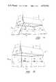
- FIG. 2is a cross sectional view of the air scrubber apparatus of FIG. 1;
- FIG. 3is a bottom view of the air scrubber apparatus of FIG. 1;
- FIGS. 4 and 5illustrate the air scrubber apparatus of FIG. 1 provided with four adjustable chain hangers for hanging up the housing thereof from the ceiling of the room, and with plexiglass panels thereunder which surround a volume located between the housing of the scrubber apparatus and the top surface of the work table; and
- FIGS. 6 and 7show a second embodiment of the air scrubber apparatus of the invention differing from the first embodiment by the position of the means for killing germs, bacteria and the like present in the purified air, and by the structure of the air filter means, this second embodiment being provided with a plexiglass wall structure thereunder defining two distinct volumes in communication therebetween in the proximity of the top surface of the work table.
- the air scrubber apparatuscomprises a housing designated generally by the reference numeral 1 which is hung up from the ceiling of for example an embalming or autopsy room above a work table disposed in this room by means of four adjustable chain hangers 2 attached respectively to one corner of a top surface 3 (see FIG. 6) of the housing 1.
- the housing designated generally by the reference numeral 1is made of sheet material, for example stainless steel or aluminium.
- the housing 1comprises a top wall 8, two inner side walls 4 and 5 and two end walls 6 and 7 defining a central compartment A.
- the housing 1also comprises two outer side walls 9 and 10 which are formed as shown on FIGS. 1 and 2 and which define with the inner side walls 4 and 5 , with four end walls 11 each located at a corresponding corner of the housing 1, and with bottom walls 12 and 13 a first longitudinal outer compartment B and a second longitudinal outer compartment C.
- the bottom walls 12 and 13constitute respectively a receptacle and reflector for cold white fluorescent tubes 14 and 15, which tubes provide sufficiently with light the top surface of the corresponding work table.
- the tube 14is mounted under the first compartment B and the tube 15 is mounted under the second outer compartment C.
- the four end walls 11are each provided with outlets to the room such as 16.
- the bottom wall of the central compartment Ais formed by two filter portions 17 and 18 each forming one half of such a bottom wall.
- metal supports 19, 20, 21, 22, 23 and 24each formed with a 90° angle are fixed to the housing 1 as shown on FIGS. 1 to 3.
- the following proceduremay be followed to mount the portions 17 and 18.
- the filter portion 18is positioned on the supports 19, 20 and 21.
- the end 25 of this portion 18is lifted to allow positioning of an holding part 26 so that a groove 28 of this holding part 26 is positioned on a rod 27 mounted transversally between the inner side walls 4 and 5, the rod 27 thereby maintaining in place the part 26.
- the end 25is released.
- the filter portion 17is introduced in the central compartment A and positioned on the supports 22, 23 and 24 and on the holding part 26.
- the structure of the filter portions 17 and 18will be further elaborated hereinafter.
- a metal mesh 29 provided with a frame 30is mounted under the filter portions 17 and 18 and held in place by adjustment between the lower parts of the walls 4, 5, 6 and 7 below the supports 19 to 24 such as 31 and 32.
- two exhaust fans 33 and 34when driven through corresponding electrical motors 35 and 36, respectively, move the foul air, produced during for example an embalming or an autopsy carried out on the work table located under the housing 1, towards the interior of the central compartment A through the metal mesh 29 and the filter portions 17 and 18 for the purpose of purifying the moved foul air.
- An ultraviolet ⁇ black light> fluorescent tube 37is mounted inside the compartment A on the top wall 8 through an holding assembly 38 to kill germs, bacteria and the like present in the purified air in the central compartment A through its ultraviolet radiation.
- the exhaust fan 33transfers a first part of the purified air from the central compartment A to the first outer compartment B for a redistribution thereof in the room through the end outlets 16 of the compartment B, and the exhaust fan 34 transfers a second part of the purified air from the central compartment A to the second outer compartment C for a redistribution thereof in the room through the end outlets 16 of the compartment C.
- the exhaust fan 33is located in a first half of the central compartment A while the exhaust fan 34 is located in the second half of this compartment A, thereby producing passage of foul air through the entire surface of the filter portions 17 and 18.
- FIG. 1shows a first switch 43 provided to energize the two fluorescent tubes 14 and 15, a second switch 41 with its associated indicating lamp 42 provided to energize the ultraviolet fluorescent tube 37, and a third switch 39 with its associated indicating lamp 40 provided to energize the two motors 35 and 36.
- the three fluorescent tubes 14, 15 and 37are energized through corresponding ballasts which are not shown on the different Figures of the attached drawings.
- the volume located between the housing 1 and the top surface of the work table disposed thereundermay be closed through a plexiglass panel structure 44 or 45 appropriately fixed to the housing 1 through parts 60 or 61 to reduce dispersion into the room of the malodorous, pungent and/or corrosive gaseous substances produced during, for example an embalming or an autopsy carried out on the work table.
- the panels of the structure (44 or 45)may be inclined (see 44 on FIG. 4) or vertical (see 45 on FIG. 5) depending on the dimensions of the top surface of the work table with respect to those of the housing 1.
- the plexiglass panel structureis provided with a panel such as 46 or 47 preferably on each side of the work table, this panel 46 or 47 being fixed at its upper side to the remainder of the structure 44 or 45 through strap-hinges 58 or 59 , for the purpose of allowing access to the interior of the plexiglass structure 44 or 45 and consequently to the top surface of the work table.
- the plexiglass panel structure 44 or 45therefore increases the efficiency of the scrubber apparatus, when used with bad smelly cases and for contagious cases, etc., by allowing working in a bacteria free environment and with no bad odors.
- the ultraviolet ⁇ black light> fluorescent tube 37 located in the central compartment Amay be replaced by a first ultraviolet ⁇ black light> fluorescent tube 48 mounted in the first outer compartment B and a second ultraviolet ⁇ black light> fluorescent tube 49 mounted in the second outer compartment C.
- the two tubes 48 and 49kill more efficiently the germs, bacteria and the like present in the purified air.
- the scrubber apparatus of FIGS. 6 and 7also comprises an air filter 65 comprising a filter portion 51 and a part 50 giving an external drawer-like to the air filter 65.
- the end wall 6has an opening 52 therein and guides 53 and 54 mounted on the inner side walls 4 and 5 are provided.
- the filter portion 51replaces both the filter portions 17 and 18 of FIG. 1 and is positioned by sliding thereof in the guides 53 and 54 through the opening 52.
- the metal mesh 29 of FIG. 1can still be mounted by adjustment between the guides 53 and 54 in the same manner as described above.
- the scrubber apparatus of FIGS. 6 and 7further comprises an outer plexiglass panel structure 55 similar to the structure 45 of FIG. 5 and provided with a panel 57 fixed to the remainder of the structure 55 through strap-hinges such as 62.
- An inner plexiglass panel structure 56is also mounted inside the structure 55 around an opening open or closed through the panel 57, and defines a volume D in contact with the top surface of the work table and accessible through the opening corresponding to the panel 57.
- the inner structure 56comprises three vertical panels having a lower end spaced from the work table thereby providing communication between the volume D and a volume E in contact with the filter portion 51.
- the only communication between on one hand the volume E, and on the other hand the volume D and the opening corresponding to the panel 57is through the spacing between the top surface of the work table and the lower end of the vertical panels of the structure 56.
- the exhaust fans 33 and 34are in operation, it can be easily appreciated with reference to FIGS. 6 and 7 that the air in the volume D defined by the inner wall structure 56 is moved from this volume D to the filter portion 51 through the volume E and the spacing between the top surface of the work table and the lower end of the vertical panels of the inner structure 56.
- Such an inner structure 56is particularly useful to move towards the filter portion 51 malodorous, pungent and/or corrosive geasous substances heavier than the air.
- Each of these filter portionscomprises a frame such as 66 and 67 (see FIGS. 1 and 2).
- a frameholds two sheets or for example polypropylene material such as 68 and 69 (see FIG. 2) provided with holes therein such as 70 (see FIG. 6) to allow passage of air therethrough.
- the volume defined between the sheets 68 and 69is filled with pellets such as 71 (see FIG. 2) of a filtering material, which sheets 68 and 69 are of course substantially rigid.
- This filtering materialis a mixture of two compounds: potassium permanganate and aluminium oxide. More particularly, the pellets of filtering material are activated pellets of aluminium oxide (Al 2 O 3 ) which are impregnated with potassium permanganate (KMnO 4 ), and constitute a very effective agent to clean the air from malodorous, pungent and/or corrosive gaseous substances.
- gaseous substancescomprise, for example, formaldehyde and all other odorous gases such as exhumation-floaters-gangrenous and other putrefactive gases, which are present during an embalming or autopsy.
- potassium permenganateis an effective oxidation agent which has the capacity to break other substances into simpler and non smelling neutral substances, such as steam and carbonic acid. This function makes the filter portions 17, 18 and 51 effective against gaseous substances such as sulphur compounds, ethylene, ammonia, and formaldehyde.
- the efficiency of the filter portionsis governed by parameters such as the quality of the filtering material, the size of the pellets, the thickness of the layer of pellets, the air speed through the filter portions, and extreme conditions of humidity or temperature.
- the activated pellets of aluminium oxide impregnated with potassium permanganateare originally of a light lilac colour. During use thereof, the pellets change color. It is therefore easy to observe the speed at which the filtering material is consumed. The penetration depth can be observed by taking out a few pellets and breaking them against a hard surface. When the change of color has reached all the way into the core of the pellet, the filtering material has been used up and should be changed. The consumed pellet is inert and can be used as, for example, filling. The advantage is due to the fact that sorbed pollution has been broken up and dispersed.
- the change of filling materialcan in future be done routinely at the same interval as was measured at the beginning, or perhaps at a shorter interval as a safety margin.
- the ultraviolet raykills all germs and bacteria instantly, in addition to the fact that the permanganate is an excellent oxidizing agent, in many instances the recirculated air in the room is in better breathing condition than the ambient air from the outside.
- the scrubber apparatustreats the air into a closed circuit, the use of the scrubber apparatus does not increase the heating or conditioning costs as no heated or cooled air is evacuated to the outside.
Landscapes
- Chemical & Material Sciences (AREA)
- Engineering & Computer Science (AREA)
- Health & Medical Sciences (AREA)
- Chemical Kinetics & Catalysis (AREA)
- Life Sciences & Earth Sciences (AREA)
- Public Health (AREA)
- General Chemical & Material Sciences (AREA)
- Epidemiology (AREA)
- Analytical Chemistry (AREA)
- Animal Behavior & Ethology (AREA)
- General Health & Medical Sciences (AREA)
- Oil, Petroleum & Natural Gas (AREA)
- Veterinary Medicine (AREA)
- Combustion & Propulsion (AREA)
- Mechanical Engineering (AREA)
- General Engineering & Computer Science (AREA)
- Disinfection, Sterilisation Or Deodorisation Of Air (AREA)
- Filtering Of Dispersed Particles In Gases (AREA)
Abstract
Description
Claims (19)
Priority Applications (2)
| Application Number | Priority Date | Filing Date | Title |
|---|---|---|---|
| US06/661,919US4553992A (en) | 1984-10-17 | 1984-10-17 | Scrubber apparatus for purifying foul air produced during an embalming, an autopsy or the like |
| US06/788,112US4666478A (en) | 1984-10-17 | 1985-10-16 | Scrubber apparatus for purifying foul air produced during an embalming, an autopsy or the like |
Applications Claiming Priority (1)
| Application Number | Priority Date | Filing Date | Title |
|---|---|---|---|
| US06/661,919US4553992A (en) | 1984-10-17 | 1984-10-17 | Scrubber apparatus for purifying foul air produced during an embalming, an autopsy or the like |
Related Child Applications (1)
| Application Number | Title | Priority Date | Filing Date |
|---|---|---|---|
| US06/788,112Continuation-In-PartUS4666478A (en) | 1984-10-17 | 1985-10-16 | Scrubber apparatus for purifying foul air produced during an embalming, an autopsy or the like |
Publications (1)
| Publication Number | Publication Date |
|---|---|
| US4553992Atrue US4553992A (en) | 1985-11-19 |
Family
ID=24655651
Family Applications (1)
| Application Number | Title | Priority Date | Filing Date |
|---|---|---|---|
| US06/661,919Expired - Fee RelatedUS4553992A (en) | 1984-10-17 | 1984-10-17 | Scrubber apparatus for purifying foul air produced during an embalming, an autopsy or the like |
Country Status (1)
| Country | Link |
|---|---|
| US (1) | US4553992A (en) |
Cited By (43)
| Publication number | Priority date | Publication date | Assignee | Title |
|---|---|---|---|---|
| US4600557A (en)* | 1983-05-31 | 1986-07-15 | Spitz Werner U | System for deodorizing and decontaminating autopsy rooms |
| USD285719S (en) | 1984-12-24 | 1986-09-16 | Conlon Daniel R | Laboratory hood |
| US4612026A (en)* | 1985-10-18 | 1986-09-16 | Pollara Frank J | Air treatment unit providing a filtration system for removing ethylene oxide from a contaminated environment |
| US4722747A (en)* | 1986-06-16 | 1988-02-02 | Armbruster Joseph M | Add-on vehicle air filtration system |
| US4732592A (en)* | 1986-10-31 | 1988-03-22 | Spengler Charles W | Portable clean air facility |
| US4750917A (en)* | 1985-02-04 | 1988-06-14 | Ebara Research Co. Ltd. | Method of and apparatus for cleaning air by irradiation of ultraviolet rays |
| US4804392A (en)* | 1987-09-17 | 1989-02-14 | Spengler Charles W | Clean air facility |
| US4806768A (en)* | 1985-10-14 | 1989-02-21 | Ubirajara Keutenedjian | Infra-red and ultra-violet air purifying apparatus |
| US4852468A (en)* | 1986-09-02 | 1989-08-01 | Mickey Harris | Work station with fume collecting means |
| US4856420A (en)* | 1988-06-20 | 1989-08-15 | Kewaunee Scientific Corporation | Fume hood |
| GB2215234A (en)* | 1988-03-09 | 1989-09-20 | Forward Team 8 Private Limited | An air filtering apparatus |
| US5112373A (en)* | 1991-06-17 | 1992-05-12 | Hung Pham | Apparatus for controlling and eliminating vapor emissions at a manicure work station |
| US5154893A (en)* | 1989-12-15 | 1992-10-13 | Masuda Harmo K.K. | Air circulator |
| US5300139A (en)* | 1993-09-13 | 1994-04-05 | Lin Shih Chiang | Air cleaner with a build-in ashtray |
| US5299557A (en)* | 1991-02-04 | 1994-04-05 | Pizza Hut, Inc. | Oven enclosure and ventilation system |
| US5336128A (en)* | 1993-08-12 | 1994-08-09 | Esau Birdsong | Nail technician's ventilator |
| WO1994020193A1 (en)* | 1993-03-05 | 1994-09-15 | Pall Corporation | Gas purification system |
| WO1996013344A1 (en)* | 1994-10-26 | 1996-05-09 | Robert Knight | Ventilated enclosure with movable canopy |
| WO1996022825A1 (en)* | 1995-01-27 | 1996-08-01 | Purafil, Inc. | Improved fiber filter and methods of use thereof |
| US5601786A (en)* | 1994-06-02 | 1997-02-11 | Monagan; Gerald C. | Air purifier |
| US5749779A (en)* | 1995-11-09 | 1998-05-12 | Wilburn's Body Shop, Inc. | Movable overhead ventilation assembly and filtering method |
| US5787903A (en)* | 1997-03-25 | 1998-08-04 | Blackshear; Mary Jane | Manicurist workstation |
| FR2760394A1 (en)* | 1997-03-07 | 1998-09-11 | Microm Laborgeraete Gmbh | SUCTION SYSTEM FOR CUTTING WASTE IN A CRYOSTATIC MICROTOME |
| US5816906A (en)* | 1997-08-01 | 1998-10-06 | Mai; Hoang T. | Vented hood with filter |
| US5997397A (en)* | 1997-06-06 | 1999-12-07 | Kendro Laboratory Products Gmbh | Laboratory workbench |
| US6004522A (en)* | 1993-12-15 | 1999-12-21 | Purafil, Inc. | Solid filtration media incorporating elevated levels of permanganate and water |
| US6338675B2 (en) | 1998-09-30 | 2002-01-15 | Rebecca Winkelman | Nail technician ventilation system |
| US6471579B1 (en)* | 1999-02-16 | 2002-10-29 | Mary Jane Blackshear | Workstation for containing organic and inorganic vapor contaminants |
| US6613277B1 (en) | 1999-06-18 | 2003-09-02 | Gerald C. Monagan | Air purifier |
| US6939397B2 (en) | 2003-05-08 | 2005-09-06 | Eco-Rx, Inc. | System for purifying and removing contaminants from gaseous fluids |
| US6974375B1 (en)* | 2004-09-21 | 2005-12-13 | Stevenson Philip A | Double vent dust collection hood with inspection lighting, storage shelf and sandpaper dispensers |
| US20080121224A1 (en)* | 2006-10-18 | 2008-05-29 | Giles Enterprises, Inc. | Ultra-violet recirculating exhaust hood system |
| US20080146132A1 (en)* | 2006-12-19 | 2008-06-19 | Miele & Cie. Kg | Exhaust hood with a vapor-collecting canopy |
| US7758836B1 (en) | 2009-04-14 | 2010-07-20 | Huggins Ronald G | System and method for removing sulfur-containing contaminants from indoor air |
| US20100294259A1 (en)* | 2004-07-23 | 2010-11-25 | Oy Halton Group Ltd. | Control of exhaust systems |
| JP4822470B1 (en)* | 2010-11-02 | 2011-11-24 | 株式会社セフテック | Autopsy specimen cover for dissection table |
| EP2498006A1 (en) | 2011-03-10 | 2012-09-12 | Miele & Cie. KG | Vapour extractor for an oven, a hotplate or similar |
| US9574779B2 (en) | 2008-04-18 | 2017-02-21 | Oy Halton Group, Ltd. | Exhaust apparatus, system, and method for enhanced capture and containment |
| US20170321877A1 (en)* | 2016-05-09 | 2017-11-09 | John Polidoro | Wall mounted hospital bed, health care facility, or other wall (or surface) type light with ultraviolet-c germicidal (or other) air decontamination system |
| USD943722S1 (en)* | 2020-02-11 | 2022-02-15 | Synexis Llc | Catalytic sail design for a dry hydrogen peroxide (DHP) generating device |
| USD944376S1 (en)* | 2020-02-11 | 2022-02-22 | Synexis Llc | Catalytic sail design for a dry hydrogen peroxide (DHP) generating device |
| US11291743B2 (en) | 2016-05-09 | 2022-04-05 | John Polidoro | Ceiling-mounted decontamination unit with luminaire |
| US20230293761A1 (en)* | 2016-05-09 | 2023-09-21 | John Polidoro | Ceiling-mounted decontamination system |
Citations (8)
| Publication number | Priority date | Publication date | Assignee | Title |
|---|---|---|---|---|
| US2369375A (en)* | 1943-05-26 | 1945-02-13 | Sonntag Bernhard | Air cleaner and purifier |
| US2886124A (en)* | 1956-07-13 | 1959-05-12 | Duct Less Hood Co Inc | Kitchen conditioner |
| US3064551A (en)* | 1960-02-15 | 1962-11-20 | Home Metal Prod Co | Vented kitchen hood |
| US3230033A (en)* | 1962-09-12 | 1966-01-18 | Lockheed Aircraft Corp | Enclosed chamber air purification apparatus |
| US3496704A (en)* | 1966-12-07 | 1970-02-24 | Broan Mfg Co Inc | Convertible hood for console range |
| US3674421A (en)* | 1968-12-31 | 1972-07-04 | Detec Sa | Apparatus for purifying and sterilizing premises |
| US3744216A (en)* | 1970-08-07 | 1973-07-10 | Environmental Technology | Air purifier |
| US4227904A (en)* | 1978-09-08 | 1980-10-14 | D-Mark, Inc. | Gas phase permeable filter |
- 1984
- 1984-10-17USUS06/661,919patent/US4553992A/ennot_activeExpired - Fee Related
Patent Citations (8)
| Publication number | Priority date | Publication date | Assignee | Title |
|---|---|---|---|---|
| US2369375A (en)* | 1943-05-26 | 1945-02-13 | Sonntag Bernhard | Air cleaner and purifier |
| US2886124A (en)* | 1956-07-13 | 1959-05-12 | Duct Less Hood Co Inc | Kitchen conditioner |
| US3064551A (en)* | 1960-02-15 | 1962-11-20 | Home Metal Prod Co | Vented kitchen hood |
| US3230033A (en)* | 1962-09-12 | 1966-01-18 | Lockheed Aircraft Corp | Enclosed chamber air purification apparatus |
| US3496704A (en)* | 1966-12-07 | 1970-02-24 | Broan Mfg Co Inc | Convertible hood for console range |
| US3674421A (en)* | 1968-12-31 | 1972-07-04 | Detec Sa | Apparatus for purifying and sterilizing premises |
| US3744216A (en)* | 1970-08-07 | 1973-07-10 | Environmental Technology | Air purifier |
| US4227904A (en)* | 1978-09-08 | 1980-10-14 | D-Mark, Inc. | Gas phase permeable filter |
Cited By (58)
| Publication number | Priority date | Publication date | Assignee | Title |
|---|---|---|---|---|
| US4600557A (en)* | 1983-05-31 | 1986-07-15 | Spitz Werner U | System for deodorizing and decontaminating autopsy rooms |
| USD285719S (en) | 1984-12-24 | 1986-09-16 | Conlon Daniel R | Laboratory hood |
| US4750917A (en)* | 1985-02-04 | 1988-06-14 | Ebara Research Co. Ltd. | Method of and apparatus for cleaning air by irradiation of ultraviolet rays |
| US4806768A (en)* | 1985-10-14 | 1989-02-21 | Ubirajara Keutenedjian | Infra-red and ultra-violet air purifying apparatus |
| US4612026A (en)* | 1985-10-18 | 1986-09-16 | Pollara Frank J | Air treatment unit providing a filtration system for removing ethylene oxide from a contaminated environment |
| US4722747A (en)* | 1986-06-16 | 1988-02-02 | Armbruster Joseph M | Add-on vehicle air filtration system |
| US4852468A (en)* | 1986-09-02 | 1989-08-01 | Mickey Harris | Work station with fume collecting means |
| US4732592A (en)* | 1986-10-31 | 1988-03-22 | Spengler Charles W | Portable clean air facility |
| US4804392A (en)* | 1987-09-17 | 1989-02-14 | Spengler Charles W | Clean air facility |
| GB2215234A (en)* | 1988-03-09 | 1989-09-20 | Forward Team 8 Private Limited | An air filtering apparatus |
| GB2215234B (en)* | 1988-03-09 | 1991-12-11 | Forward Team 8 Private Limited | An air filtering apparatus |
| US4856420A (en)* | 1988-06-20 | 1989-08-15 | Kewaunee Scientific Corporation | Fume hood |
| US5154893A (en)* | 1989-12-15 | 1992-10-13 | Masuda Harmo K.K. | Air circulator |
| US5299557A (en)* | 1991-02-04 | 1994-04-05 | Pizza Hut, Inc. | Oven enclosure and ventilation system |
| US5112373A (en)* | 1991-06-17 | 1992-05-12 | Hung Pham | Apparatus for controlling and eliminating vapor emissions at a manicure work station |
| WO1994020193A1 (en)* | 1993-03-05 | 1994-09-15 | Pall Corporation | Gas purification system |
| US5336128A (en)* | 1993-08-12 | 1994-08-09 | Esau Birdsong | Nail technician's ventilator |
| US5300139A (en)* | 1993-09-13 | 1994-04-05 | Lin Shih Chiang | Air cleaner with a build-in ashtray |
| US6004522A (en)* | 1993-12-15 | 1999-12-21 | Purafil, Inc. | Solid filtration media incorporating elevated levels of permanganate and water |
| US5601786A (en)* | 1994-06-02 | 1997-02-11 | Monagan; Gerald C. | Air purifier |
| WO1996013344A1 (en)* | 1994-10-26 | 1996-05-09 | Robert Knight | Ventilated enclosure with movable canopy |
| US6265024B1 (en) | 1995-01-27 | 2001-07-24 | Purafil, Inc. | Fiber filter and methods of use thereof |
| WO1996022825A1 (en)* | 1995-01-27 | 1996-08-01 | Purafil, Inc. | Improved fiber filter and methods of use thereof |
| US5942323A (en)* | 1995-01-27 | 1999-08-24 | Purafil, Inc. | Fiber filter and methods of use thereof |
| US5749779A (en)* | 1995-11-09 | 1998-05-12 | Wilburn's Body Shop, Inc. | Movable overhead ventilation assembly and filtering method |
| FR2760394A1 (en)* | 1997-03-07 | 1998-09-11 | Microm Laborgeraete Gmbh | SUCTION SYSTEM FOR CUTTING WASTE IN A CRYOSTATIC MICROTOME |
| US5787903A (en)* | 1997-03-25 | 1998-08-04 | Blackshear; Mary Jane | Manicurist workstation |
| US5997397A (en)* | 1997-06-06 | 1999-12-07 | Kendro Laboratory Products Gmbh | Laboratory workbench |
| US5816906A (en)* | 1997-08-01 | 1998-10-06 | Mai; Hoang T. | Vented hood with filter |
| US6338675B2 (en) | 1998-09-30 | 2002-01-15 | Rebecca Winkelman | Nail technician ventilation system |
| US6471579B1 (en)* | 1999-02-16 | 2002-10-29 | Mary Jane Blackshear | Workstation for containing organic and inorganic vapor contaminants |
| US6613277B1 (en) | 1999-06-18 | 2003-09-02 | Gerald C. Monagan | Air purifier |
| US6939397B2 (en) | 2003-05-08 | 2005-09-06 | Eco-Rx, Inc. | System for purifying and removing contaminants from gaseous fluids |
| US11242999B2 (en) | 2004-07-23 | 2022-02-08 | Oy Halton Group Ltd. | Control of exhaust systems |
| US20100294259A1 (en)* | 2004-07-23 | 2010-11-25 | Oy Halton Group Ltd. | Control of exhaust systems |
| US10184669B2 (en) | 2004-07-23 | 2019-01-22 | Oy Halton Group Ltd | Control of exhaust systems |
| US8444462B2 (en)* | 2004-07-23 | 2013-05-21 | Oy Halton Group Ltd. | Control of exhaust systems |
| US9011215B2 (en) | 2004-07-23 | 2015-04-21 | Oy Halton Group Ltd. | Control of exhaust systems |
| US9188354B2 (en) | 2004-07-23 | 2015-11-17 | Oy Halton Group Ltd. | Control of exhaust systems |
| US6974375B1 (en)* | 2004-09-21 | 2005-12-13 | Stevenson Philip A | Double vent dust collection hood with inspection lighting, storage shelf and sandpaper dispensers |
| US20080121224A1 (en)* | 2006-10-18 | 2008-05-29 | Giles Enterprises, Inc. | Ultra-violet recirculating exhaust hood system |
| US20080146132A1 (en)* | 2006-12-19 | 2008-06-19 | Miele & Cie. Kg | Exhaust hood with a vapor-collecting canopy |
| US10471482B2 (en) | 2008-04-18 | 2019-11-12 | Oy Halton Group Ltd. | Exhaust apparatus, system, and method for enhanced capture and containment |
| US9574779B2 (en) | 2008-04-18 | 2017-02-21 | Oy Halton Group, Ltd. | Exhaust apparatus, system, and method for enhanced capture and containment |
| US7758836B1 (en) | 2009-04-14 | 2010-07-20 | Huggins Ronald G | System and method for removing sulfur-containing contaminants from indoor air |
| JP4822470B1 (en)* | 2010-11-02 | 2011-11-24 | 株式会社セフテック | Autopsy specimen cover for dissection table |
| DE102011001184A1 (en) | 2011-03-10 | 2012-09-13 | Miele & Cie. Kg | Extractor hood for a stove, a hob or the like |
| DE102011001184B4 (en)* | 2011-03-10 | 2012-11-22 | Miele & Cie. Kg | Extractor hood for a stove, a hob or the like |
| EP2498006A1 (en) | 2011-03-10 | 2012-09-12 | Miele & Cie. KG | Vapour extractor for an oven, a hotplate or similar |
| US20170321877A1 (en)* | 2016-05-09 | 2017-11-09 | John Polidoro | Wall mounted hospital bed, health care facility, or other wall (or surface) type light with ultraviolet-c germicidal (or other) air decontamination system |
| US10808964B2 (en)* | 2016-05-09 | 2020-10-20 | John Polidoro | Wall mounted hospital bed, health care facility, or other wall (or surface) type light with Ultraviolet-C germicidal (or other) air decontamination system |
| US11293665B2 (en) | 2016-05-09 | 2022-04-05 | John Polidoro | Wall or surface mounted light fixture with an air decontamination system |
| US11291743B2 (en) | 2016-05-09 | 2022-04-05 | John Polidoro | Ceiling-mounted decontamination unit with luminaire |
| US11660368B2 (en) | 2016-05-09 | 2023-05-30 | John Polidoro | Ceiling-mounted decontamination unit with luminaire |
| US20230293761A1 (en)* | 2016-05-09 | 2023-09-21 | John Polidoro | Ceiling-mounted decontamination system |
| US12016983B2 (en)* | 2016-05-09 | 2024-06-25 | John Polidoro | Ceiling-mounted decontamination system |
| USD943722S1 (en)* | 2020-02-11 | 2022-02-15 | Synexis Llc | Catalytic sail design for a dry hydrogen peroxide (DHP) generating device |
| USD944376S1 (en)* | 2020-02-11 | 2022-02-22 | Synexis Llc | Catalytic sail design for a dry hydrogen peroxide (DHP) generating device |
Similar Documents
| Publication | Publication Date | Title |
|---|---|---|
| US4553992A (en) | Scrubber apparatus for purifying foul air produced during an embalming, an autopsy or the like | |
| US4666478A (en) | Scrubber apparatus for purifying foul air produced during an embalming, an autopsy or the like | |
| US4545540A (en) | Apparatus for storing mercury-containing used products | |
| DK170140B1 (en) | Process for preparing an absorbent or sorbent material for use in an apparatus for releasing a gaseous material into the atmosphere | |
| US6346143B1 (en) | Odor adsorptive filter for refrigerators and freezers | |
| US4875914A (en) | Gas & odor adsorbing unit | |
| US3606998A (en) | Room freshener and deodorizer | |
| US2640558A (en) | Air purifying and circulating device | |
| KR20180094255A (en) | Air cleaner for kitchen and air cleaning system having the same | |
| CN105711966B (en) | Dampproofing odour removal device that disinfects suitable for in airtight space | |
| JP3054529B2 (en) | Cold storage | |
| JPH01189321A (en) | Deodorizer for refrigerator | |
| CA1220016A (en) | Scrubber apparatus for purifying foul air produced during an embalming, an autopsy or the like | |
| JP2006097982A (en) | Range food | |
| JP3145077U (en) | Dehydration apparatus and glove box | |
| JP2002333266A (en) | Refrigerator | |
| GB2290044A (en) | Glove boxes | |
| JP2994949B2 (en) | Cold storage | |
| JP3937094B2 (en) | Body storage deodorization cooler | |
| CN205525859U (en) | Dampproofing odour removal device that disinfects suitable for in airtight space | |
| JP2742377B2 (en) | Ozone generator | |
| CN210613774U (en) | Multifunctional experiment table for chemical experiments | |
| JPS63135727A (en) | air conditioner | |
| JP2004144324A (en) | Deodorizing device for refrigerator, and refrigerator provided with the same | |
| JPH0395379A (en) | Deodorizing device for refrigerator, etc |
Legal Events
| Date | Code | Title | Description |
|---|---|---|---|
| AS | Assignment | Owner name:E.F.C. CONTROL INC., 230, SEIGNEURIALE, BEAUPORT, Free format text:ASSIGNMENT OF ASSIGNORS INTEREST.;ASSIGNORS:BOISSINOT, JEAN-GUY;BEGIN, PIERRE;REEL/FRAME:004660/0727 Effective date:19860707 Owner name:E.F.C. CONTROL INC., CANADA Free format text:ASSIGNMENT OF ASSIGNORS INTEREST;ASSIGNORS:BOISSINOT, JEAN-GUY;BEGIN, PIERRE;REEL/FRAME:004660/0727 Effective date:19860707 | |
| FEPP | Fee payment procedure | Free format text:PAYER NUMBER DE-ASSIGNED (ORIGINAL EVENT CODE: RMPN); ENTITY STATUS OF PATENT OWNER: SMALL ENTITY Free format text:PAYOR NUMBER ASSIGNED (ORIGINAL EVENT CODE: ASPN); ENTITY STATUS OF PATENT OWNER: SMALL ENTITY | |
| FEPP | Fee payment procedure | Free format text:PAYOR NUMBER ASSIGNED (ORIGINAL EVENT CODE: ASPN); ENTITY STATUS OF PATENT OWNER: SMALL ENTITY | |
| FPAY | Fee payment | Year of fee payment:4 | |
| REMI | Maintenance fee reminder mailed | ||
| LAPS | Lapse for failure to pay maintenance fees | ||
| FP | Lapsed due to failure to pay maintenance fee | Effective date:19930912 | |
| STCH | Information on status: patent discontinuation | Free format text:PATENT EXPIRED DUE TO NONPAYMENT OF MAINTENANCE FEES UNDER 37 CFR 1.362 |