US4553958A - IV Delivery controller - Google Patents
IV Delivery controllerDownload PDFInfo
- Publication number
- US4553958A US4553958AUS06/463,976US46397683AUS4553958AUS 4553958 AUS4553958 AUS 4553958AUS 46397683 AUS46397683 AUS 46397683AUS 4553958 AUS4553958 AUS 4553958A
- Authority
- US
- United States
- Prior art keywords
- fluid
- primary
- display
- container
- infused
- Prior art date
- Legal status (The legal status is an assumption and is not a legal conclusion. Google has not performed a legal analysis and makes no representation as to the accuracy of the status listed.)
- Expired - Fee Related
Links
Images


Classifications
- A—HUMAN NECESSITIES
- A61—MEDICAL OR VETERINARY SCIENCE; HYGIENE
- A61M—DEVICES FOR INTRODUCING MEDIA INTO, OR ONTO, THE BODY; DEVICES FOR TRANSDUCING BODY MEDIA OR FOR TAKING MEDIA FROM THE BODY; DEVICES FOR PRODUCING OR ENDING SLEEP OR STUPOR
- A61M5/00—Devices for bringing media into the body in a subcutaneous, intra-vascular or intramuscular way; Accessories therefor, e.g. filling or cleaning devices, arm-rests
- A61M5/14—Infusion devices, e.g. infusing by gravity; Blood infusion; Accessories therefor
- A61M5/168—Means for controlling media flow to the body or for metering media to the body, e.g. drip meters, counters ; Monitoring media flow to the body
- A61M5/172—Means for controlling media flow to the body or for metering media to the body, e.g. drip meters, counters ; Monitoring media flow to the body electrical or electronic
- A—HUMAN NECESSITIES
- A61—MEDICAL OR VETERINARY SCIENCE; HYGIENE
- A61M—DEVICES FOR INTRODUCING MEDIA INTO, OR ONTO, THE BODY; DEVICES FOR TRANSDUCING BODY MEDIA OR FOR TAKING MEDIA FROM THE BODY; DEVICES FOR PRODUCING OR ENDING SLEEP OR STUPOR
- A61M5/00—Devices for bringing media into the body in a subcutaneous, intra-vascular or intramuscular way; Accessories therefor, e.g. filling or cleaning devices, arm-rests
- A61M5/14—Infusion devices, e.g. infusing by gravity; Blood infusion; Accessories therefor
- A61M5/168—Means for controlling media flow to the body or for metering media to the body, e.g. drip meters, counters ; Monitoring media flow to the body
- A61M5/16804—Flow controllers
- A61M5/16827—Flow controllers controlling delivery of multiple fluids, e.g. sequencing, mixing or via separate flow-paths
- Y—GENERAL TAGGING OF NEW TECHNOLOGICAL DEVELOPMENTS; GENERAL TAGGING OF CROSS-SECTIONAL TECHNOLOGIES SPANNING OVER SEVERAL SECTIONS OF THE IPC; TECHNICAL SUBJECTS COVERED BY FORMER USPC CROSS-REFERENCE ART COLLECTIONS [XRACs] AND DIGESTS
- Y10—TECHNICAL SUBJECTS COVERED BY FORMER USPC
- Y10S—TECHNICAL SUBJECTS COVERED BY FORMER USPC CROSS-REFERENCE ART COLLECTIONS [XRACs] AND DIGESTS
- Y10S128/00—Surgery
- Y10S128/13—Infusion monitoring
Definitions
- This inventionrelates to the intravenous delivery of fluids to a patient, and in particular to a controller permitting fluid delivery of either one or two fluids at predetermined rates to infuse predetermined volumes.
- IVintravenous delivery
- fluidscan comprise, for example, nutritional fluids and drugs, such as antibiotics.
- a primary containeris provided which holds a volume of a primary fluid, such as a nutrient.
- a secondary containeris also provided, containing a secondary fluid.
- the secondary fluidis commonly a drug or medicament.
- Fluid flow linesextend from each of the containers to a Y-connection beneath the containers.
- a check valve or another one-way flow deviceis positioned in the flow line from the primary container between the primary container and Y-connection.
- the secondary containeris maintained at an elevation above the primary container. Therefore, the hydrostatic pressure of the secondary fluid is sufficient to close the check valve in the primary fluid flow line and block flow from the primary container until the secondary container is empty. When the secondary fluid has been infused, the check valve will open, permitting infusion of the primary fluid.
- any IV delivery systemcritical factors that must be recognized are the necessity to design the delivery system so that the system can be operated with a minimum of effort and training and the necessity to minimize opportunities for the operator to incorrectly set the infusion conditions.
- the nurse, or other operatormust be able to thoroughly understand the procedure to establish the desired flow.
- the procedure to set the desired flow ratesshould be designed to occupy the minimum of the nurse's time. Therefore, a delivery system is needed which permits the nurse to thoroughly understand the procedure for initiating and setting flow rates.
- This inventioncontemplates a method and apparatus for a controller used in intravenous infusions of a single fluid or infusions of a primary fluid from a primary container and a secondary fluid from a secondary container in which the secondary fluid is delivered at a first predetermined rate until a preselected volume or time of delivery has occurred and the primary fluid is subsequently delivered at a second predetermined rate.
- Container display meansprovide a visible representation of both the primary and secondary containers, and infusion data display means can display a first display in association with the representation of the secondary container showing the first predetermined rate of instantaneous infusion data for fluid infused at that rate.
- the display meanscan also produce a second display, in association with the visible representation of the primary container, showing the second predetermined rate and instantaneous infusion data for delivery at the second rate.
- Instantaneous infusion data for a given ratemay be, for example, the volume delivered at that rate at the time of display.
- Flow activation display meansare provided to generate a visible indication of the activation of flow from each container to the patient.
- each container representationencompasses the display of the infusion data pertaining to its fluid.
- FIG. 1illustrates a fluid delivery system having primary and secondary fluid containers incorporating a controller forming a first embodiment of the present invention
- FIG. 2Aillustrates the controller and the display panel thereon
- FIG. 2Billustrates detail of the fluid flow line displays on the controller
- FIG. 3illustrates a block diagram of the internal electronic components of the controller
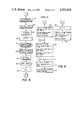
- FIGS. 4, 5 and 6are flow charts representing the logic of the controller under normal operation
- FIGS. 7A, 7B, 7C and 8are flow charts representing the logic of the controller in an alarm condition.
- FIG. 9is a flow chart representing the logic of the controller in a reset condition subsequent to completion of infusion or an alarm condition.
- the IV delivery systemincludes a primary container 12 and a secondary container 14.
- the primary container 12contains a quantity of a primary fluid 16, such as a nutritional fluid.
- the secondary containercontains a secondary fluid 18, such as an antibiotic.
- the secondary container 14is suspended above the primary container 12 by hanging the primary container 12 from a rod 20 off of stand 22.
- a primary fluid line 24extends from the primary container 12.
- a secondary fluid line 26extends from the secondary container 14. The lines 24 and 26 merge at Y-connection 28.
- a check valve 30is positioned in the primary fluid line 24 to prevent back flow towards the primary container. This check valve 30 also insures that the secondary fluid will be infused first by gravity flow as the secondary fluid pressure maintains the check valve closed while secondary fluid 18 remains in the secondary container 14. Once the secondary container 14 has emptied, the check valve 30 will open, permitting infusion of the primary fluid from the primary container 12.
- a fluid line 32extends from the Y-connection 28 into controller 34.
- a fluid line 36extends from the controller 34 to the patient.
- the controller 34acts to meter fluid from the primary and secondary containers at a rate and volume to be determined by the operator as described in greater detail hereinafter.
- the controller 34includes a cassette section 38 for holding a metering cassette 40, and a display section 42 for input and display of information.
- the fluid lines 32 and 36attach to the cassette 40.
- the cassette 40includes a flexible diaphragm therein and two separate flow paths therethrough.
- the cassette 40 and activating structure in controller 34act to meter a predetermined amount of fluid at a variable selected flow rate.
- a door 41closes cassette section 38 when the controller is in operation.
- the details of the cassette and controller operating structureare described in copending U.S. patent applicaion Ser. No. 404,811, filed Aug. 3, 1982 for a Volumetric Metering Unit for Intravenous Fluid Addition, application Ser. No. 258,361, filed Apr. 28, 1981, for an Intravenous Drug Additive Delivery System with Electronic Control and application Ser. No. 258,362, filed Apr. 28, 1981, for a Flow Fault Sensing System, the disclosure of each of which is hereby incorporated by reference as if fully disclosed and set forth herein.
- controller 34The components of controller 34 are diagrammatically illustrated in FIG. 3.
- a microprocessor based control unit 44is provided.
- a keyboard 45communicates with the control unit 44 through a control unit/keyboard interface 46.
- a display panel 48interacts with the control unit 44 through a control unit/display panel interface unit 50.
- Control unit 44communicates with the cassette operating mechanism 52 which controls operation of the cassette 40.
- the control unit 44directs the operation of the cassette 40 through mechanism 52 and the mechanism 52 provides information to the control unit as to the flow metered through the cassette 40.
- An alarm 53 and a memory 54are associated with the control unit 44.
- Various alarm sensorsare also connected to control unit 44: battery condition sensor 55, door open sensor 56, air-in-line sensor 57 and occlusion sensor 58.
- Door open sensor 56senses when the door 41 covering the cassette 14 is ajar.
- Air in line sensor 57senses when air has entered the fluid flow line at the position of the sensor 57 to prevent entry of air into the veins of the patient.
- Occlusion sensor 58which informs the control unit when a blockage has occurred which stops or substantially slows fluid through the delivery system 10.
- Battery condition sensor 55operates when the unit is in d.c. operating mode to advise of battery weakness.
- Alarm 53is provided and controlled by control unit 44 to inform the operator of an emergency situation. When any of the alarm sensors 55-58 is activated, control unit 44 turns on alarm 53 to sound an audible alarm and flash the appropriate alarm legend described below.
- Display section 42includes keyboard 45 and a display panel 48.
- Display panel 48includes a dual container display section 59, a dual flow line display section 60, an instruction legends section 61, and an alarm legends section 62.
- Keyboard 45is provided with ten keys 64 corresponding to the numerals 0-9 for input of data to keyboard. Enter button 66 is provided for entry of the data. A clear key 68 is provided for erasing current data to make corrections. Other keys provided, the function of which will be discussed below are: run key 70 bearing run light 72; hold key 74; alarm reset key 76; V.T.B.I. (volume to be infused) recall key 78; primary set up key 82; and secondary set up key 84. Each of the keys on keyboard 45 enter data or commands into the control unit 44 through interface 46.
- Dual container display 59 of display panel 48includes a graphic representation of a primary fluid container 86 and a graphic representation of a secondary fluid container 88.
- Primary fluid container representation 86is presented so as to be readily distinguishable visually from the secondary fluid container representation 88.
- representation 86depicts a larger container, and extends below the bottom of representation 88, both suggestive of typical physical and spatial relationship of the actual containers 12 and 14.
- the words "primary” and “secondary" identifying each representationare positioned above representations 86 and 88.
- the container representations 86 and 88are the only portions of display panel 48 which are provided in visible form at all times for the viewer. All other elements of information, legends, data or other display on display panel 48 are provided by light means so as to be visible only when and if directed by control unit 44 through interface 50.
- Infusion data section 90Associated with primary container representation 86 is a primary infusion data section 90, preferably located within representation 86.
- Infusion data section 90includes a numerical register 92 accompanied by the legend "rate” 94, and a second numerical register 96 accompanied by the legends "volume . . . infused” 98, and "to be” 100, each of which is separately controlled by control unit 44.
- the legends 98 and 100may be selectively activated to read either "volume infused” or "volume to be infused.”
- Infusion data section 104includes a numerical register 106 accompanied by the legend "rate” 108, and a second numerical register 110 accompanied by the following separately controlled legends: "volume . . . infused” 112, and "to be” 114.
- each container representationhas means for graphical presentation of the desired infusion data for that particular container associated therewith.
- desired infusion datais presented in the form of desired volume and rate, it could be presented as desired volume and desired time of infusion.
- Dual flow line display section 60includes primary flow line display 118 depending from primary container display 86 and secondary flow line display 120 depending from secondary container display 88.
- Flow line displays 118 and 120meet in the central area of section 60 and combined flow line display 122 proceeds downwardly from their point of joinder.
- Primary flow line display 118is composed of a repeating series of three discretely controlled segments 124, 126 and 128.
- secondary flow line display 120is formed by a repeating series of three discretely controlled segments 130, 132 and 134.
- combined flow line display 122is formed by repeating segments 136, 138 and 140. The commonly numbered segments (1, 2 or 3) in each flow line 118, 120 and 122 are controlled together.
- Instruction legends section 61consists of a series of discretely controlled legends which are activatable by control unit 44 to prompt the operator as possible.
- the legendsare as follows:
- Alarm legends section 62likewise contains several discrete message legends for activation by the control unit 44:
- FIGS. 4-6illustrate the normal operation of the controller.
- the operatormust initially provide power to the controller as represented by keyboard input 164, preferably by a switch (not shown) located behind door 41.
- the cassette 40will not yet be installed and the door 41 will be open.
- Thiswill cause the control unit 44 to display a "door open” legend 152 on display 48 as represented by prompt or alarm action 166, informing the operator that the door is open.
- the operatorwill then insert a cassette 40 into the controller 34 and close the door 41, as represented in the operator action 168.
- the control unit 44senses the closure of the door through door open sensor 56 and turns off the "door open” legend 152 in control unit action 170.
- the control unit 44then proceeds to zero the primary and secondary volume infused registers in the memory 54.
- the control unit 44also enables the keyboard 45 and commands the display to illuminate the primary "rate” legend 94 and corresponding numerical display 92, both associated with primary container representation 86 on display 48. These control unit activities are represented by control unit action 175.
- the display 48is then activated to illuminate the "set primary,” “rate,” and “and push enter” legends 141, 143 and 145, in the instruction section 61, as shown in prompt or alarm action 176.
- the instruction section 61thus prompts the operator to "set primary rate and push enter.”
- the operatorenters the desired primary flow rate by means of the numeric keys 64, and presses enter key 66, as represented by keyboard input 178, to cause the desired primary flow rate to appear in display 92.
- the control unit 44then directs the display 48 to display the "set primary,” "volume to be infused” and “and push enter” displays 141, 144 and 145, in instruction section 61, as represented by prompt or alarm action 180.
- the control unit 44then directs the display 48 to activate volume register display 96 and the "volume to be infused” legends 98 and 100 associated with primary container representation 86, in control unit action 182.
- the operatorenters the desired volume and pushes the enter button 66 as represented by keyboard input 186, to cause the desired volume to be entered in display 96.
- the display 48illuminates the "set secondary” display 142, and the "or start infusion" display 146 as represented by prompt or alarm action 188.
- the control unit 44will initiate infusion of the primary fluid at the selected flow rate until a volume equal to the selected volume to be infused has been metered through cassette 40.
- the display 92will continuously display the rate during the infusion.
- the display 96will, at all times during infusion, display the instantaneous volume of fluid already metered through controller 34, together with the legend "volume infused” 98.
- control unit 44will then operate to cease display of the legend "to be” 100, leaving on the "volume infused” legend 98.
- the control unit 44will then display on the primary volume infused display 96 the instantaneous volume of primary fluid delivered to the patient.
- the control unit 44will operate the primary fluid flow line display 118 shown in FIG. 2B by sequentially activating and deactivating the individual displays 124, 126 and 128 forming the flow line display 118 to represent flow out of the primary container.
- the combined fluid flow line display 122also contains three display elements, 136, 138 and 140. These elements will also be sequentially activated and deactivated to represent flow to the patient through the combined fluid flow line.
- An important feature of the controlleris the display during primary fluid infusion of only the primary fluid flow rate and volume and the flow displays 118, 122 and light 72 during infusion. The operator is immediately aware of which fluid is being infused and is not distracted by extraneous information.
- the primary fluidwill be infused at the selected primary rate until the total fluid infused equals the primary volume to be infused as illustrated in control unit action 236.
- the control unitstops infusion and sets off the alarm 53 and "infusion complete" display 154 to indicate to the operator that the infusion is complete.
- the alarmwill only be deactivated when the operator presses the alarm reset button 76.
- a small infusion ratecan be programmed into the system to keep the vein open for additional infusion at a later time by continuing flow from the primary container at a low rate. If the keep open rate is used, a "keep open rate" display 148 appears.
- control unit 44will zero the secondary volume infused register, as represented by control unit action 201.
- the "set secondary,” “rate” and “and push enter,” displays 142, 143, and 145are activated, as represented by prompt or alarm action 191.
- Control unit 44proceeds to activate the secondary rate numerical display 106 and the "rate” legend 108 as represented by control unit action 192.
- the operatorthen enters the secondary rate into keys 64 and presses the enter button 66, represented by operator action 194.
- the control unitdirects the secondary volume display 110 and secondary volume legends "volume to be infused” 112 and 114 to be activated, as represented by control unit action 208.
- the operatorthen enters the desired secondary fluid volume to be infused through the keys 64 and presses the enter button 66, as represented by operator action 210.
- control unit 44will then prompt the operator to initiate infusion by display of only the words "start infusion" (independently activated) in display 146 as represented by prompt or alarm action 212.
- the operatorwill then depress the run button 70 as represented by operator action 216.
- the secondary fluidwill be delivered first.
- the controllerwill initially stop display of the legend "to be” 114 to leave on "volume infused" display 112.
- the primary rate display 92 and legend "rate” display 94 and primary volume to be infused display 96 and legends "volume to be infused” 98 and 100will also be deactivated to avoid confusion of the operator.
- the secondary fluid flow line display 20 and the combined fluid flow line display 122will become activated.
- the secondary fluid flow line display 120includes display elements 130, 132 and 134 which again flash sequentially to simulate flow from the secondary container to the patient.
- the running light 72will also flash.
- the keyboard 45is disabled.
- the controllerthen proceeds to control flow through the cassette 40 to a rate equal to the desired secondary fluid infusion rate until the total flow through the cassette equals the secondary fluid volume to be infused.
- Secondary volume display 110shows the instantaneous volume of fluid metered so that the operator can observe how much fluid has been infused.
- the secondary rate display 106continues to display the rate to remind the operator.
- the secondary fluidwill be infused before the primary fluid because the hydrostatic head of the secondary fluid keeps check valve 30 closed, preventing flow of the primary fluid. Therefore, if the volume of secondary fluid in the secondary container 14 is equal to the volume to be infused, the secondary container will empty precisely when the controller 34 has metered the desired secondary fluid volume to be infused and the infusion of primary fluid will begin. However, it is common to overfill such secondary containers by 10% to 15%. This will cause the overfill amount to be infused at the primary fluid rate. However, this is rarely a problem as the critical factor is usually to deliver at least the desired quantity of secondary fluid within a set time limit. The flow rate and quantity input of primary fluid is typically less critical.
- control unit action 254Infusion of the primary fluid occurs at the primary fluid flow rate until the primary fluid volume to be infused is achieved as represented by control unit actions 236 and 242. Displays are maintained as in primary fluid flow described above.
- the controllerdisplays only information regarding the actual fluid rate being infused, again avoiding operator confusion.
- the alarm logicis illustrated in FIGS. 7A, 7B, 7C and 8.
- the controllerwill enter the infusion complete alarm condition 256. This comparison is illustrated as control unit action 258.
- KVO flowkeep vein open flow rate
- the controllermaintains a set rate of flow through the cassette, typically 10 cc per hour, as represented by the control unit action 260.
- the control unitwill also activate the legend "keep open rate" display 148 to inform the operator, as represented by prompt or alarm action 262.
- the alarm 53will then be activated as represented by control unit action 264.
- the controlleractivates the "infusion complete” legend 154 as represented by prompt or alarm display 266.
- the operatorTo stop the alarm, the operator must manually push the alarm reset button 76 as represented by operator action 268.
- the operatorhas three options: to turn off the controller, reset the system or continue the keep open flow. If the operator wishes to shut off the controller, a power on/off switch (not shown) will be activated to shut down the controller as represented by operator action 270. If the operator wishes to reset the controller, the operator will depress the primary setup button 82 as represented by keyboard input 273. The control unit will turn off the legends 148 and 154, as represented by control unit action 275, and return in a loop to the logic illustrated in FIG. 4 denoted by the arrow A for resetting the primary and secondary fluid delivery rates and volumes as desired. The third option is to push the run button 72, as represented by keyboard input 276. The control unit will then disable the alarm reset button 76 and maintain the keep open rate. The control unit totalizes the flow delivered to inform the operator of the total keep vein open flow. The sensing of an occlusion or air-in-line condition will immediately cease the infusion. These actions are represented by control unit actions 274 and 278.
- An occlusion alarm condition 290is provided.
- An occlusionis sensed by detecting inadequate motion of the flexible diaphragm within the cassette 40.
- a mechanism by which the motion may be sensedis described in U.S. patent application Ser. No. 258,362, filed Apr. 28, 1981, which disclosure is incorporated by reference herein. This action is represented by control unit action 292. If inadequate motion is sensed, the control unit 44 sets the arbitrary time function T to 0 and enters a slow alarm condition as represented by control unit action 294. The conrol unit will cause the display of the "occlusion" legend 153 as represented by prompt or alarm action 298.
- control unit decision 300If, in fact, the membrane is moving, as represented by control unit decision 300, the control unit will cease the alarm condition as represented by control unit action 302 in FIG. 8 and proceed with infusion by entering the running condition logic at either point B or point C, depending upon whether both primary and secondary flow is desired or whether only primary flow is desired or remaining in the infusion condition.
- control unitwill remain in a loop, including control unit actions 300 and 304, until the value of T exceeds two minutes.
- a two minute delayis provided to prevent an alarm everytime a short time occlusion occurs, for example, if the patient rolled over onto the flow line to constrict it for a short period.
- the alarmwill be activated and the controller will set a flow rate through the cassette 40 equal to a keep open rate, such as 10 cc per hour, as illustrated in the control unit action 306.
- the activation of the keep open ratewill be made known to the operator by the display of the "keep open rate" display 148 as represented by prompt or alarm action 307.
- control unitdeactivates the occlusion display 153 as represented by control unit action 314, deactivates the alarm condition as represented by control unit action 302 and reinitiates infusion.
- the IV delivery system 10can be provided with an air-in-line sensor 57 along a fluid flow line to detect when air is in the flow line. It can be fatal for a patient to have air enter his veins. Therefore, an air-in-line alarm condition 328 is provided.
- the sensor 57Upon sensing of air in a fluid line, the sensor 57 communicates with the control unit 44 as represented by control unit action 330.
- the control unitinstantly stops flow through the cassette 40 and deactivates all fluid flow line displays (118, 120 and 122) and the running light 72 as represented by control unit action 332.
- the alarm 53is then sounded as represented by control unit action 334 and the legend "air-in-line" display 150 is activated as represented by prompt or alarm action 338. This prevents any air from entering the vein of the patient.
- control unit decision 342the operator must press the alarm reset button 76 as represented by operator action 340.
- the aircan still be retained in the flow line.
- the control unittherefore reevaluates the content of air in the flow line as represented by control unit decision 342. If the air has been eliminated, the operator can depress the run button 70 to reinitiate flow as represented by keyboard input 344.
- the control unitwill stop display of the "air-in-line" display 150, as represented by control unit action 345. If too much air remains, the operator will be required to open the door 41, remove the cassette 40 and purge the cassette and flow lines of air as represented by operator action 346. When the door is open, the control unit will automatically activate the "door open" display 152 as represented by prompt or alarm action 348.
- control unitsenses the closure of the door and deactivates the display 152 as represented by control unit action 352.
- the operatorcan then reinitiate operation of the controller by pushing the run button 70 as represented by the operator action 354.
- the control unitdeactivates the "air-in-line" display 190 and reinitiates infusion as represented by control unit action 356.
- the cassette door alarm condition 370is operative whenever door 41 is open.
- the door open sensor 56communicates the open door information to the control unit 44 as represented by control unit action 372.
- the control unitdetermines whether the controller is operating as represented by control unit decision 374. If not, the control unit activates the "door open" display 152 as represented by prompt or alarm condition 376 until the operator closes the door, represented by operator action 378.
- the display 152is then deactivated as illustrated in control unit action 380.
- the "door open" display 152will also be activated as represented by prompt and alarm condition 382 and the alarm 53 will also be activated as represented by control unit action 384.
- the control unitalso stops flow through the cassette 40 as illustrated by control unit action 386.
- the operatormust press the alarm reset button 76, rectify the open door condition, and press the run button 70 before flow can again proceed. These steps are represented by keyboard inputs and operator action 388, 390 and 392.
- the control unitthen turns off the display 152 as represented by control unit action 394 and reinitiates infusion.
- the controllerwill include a battery condition sensor 55 for detecting the remaining power reserve in the battery.
- the battery alarm condition 404is activated when the sensor 55 senses a battery charge of less than 24 hours as represented by control unit action 406.
- the control unitwill activate the "low battery" display 151 as represented by prompt or alarm condition 410.
- the operator's attentioncan be attracted to the low battery condition by flashing the flow line displays 118, 120 and 122 at a constant rate, for example, every two seconds for a one quarter to one half second display as illustrated by control unit action 412.
- the reset conditionsare illustrated in FIG. 9. A reset will be necessary every time a new primary or secondary container is hung and whenever a different flow rate is desired. The reset will also be necessary after each alarm condition. If a new secondary container is to be hung, as represented by control unit action 420, the operator will push the secondary setup button 84 as represented by keyboard input 422. This action will cause the control unit to stop infusion and deactivate all flow line displays, as well as running light 72, as represented by control unit action 424. The control unit will also zero the secondary fluid volume to be infused display 110 and rate display 106. The desired secondary fluid rate and volume can then be input into controller 34 to infuse the secondary fluid as described hereinabove.
- control unit action 428If a new primary container is hung, as represented by control unit action 428, the operator will push the primary setup button 82 as represented by keyboard input 430. The control unit will again stop infusion and deactivate the flow line displays and running light 72 as represented by control unit action 432. The operator can then set in the primary fluid flow rate and volume and secondary fluid flow rate and volume as described hereinabove.
- control unit action 433With the creation of alarm condition, represented by control unit action 433, the control unit will turn on the appropriate alarm 53, which can comprise both a visual and an audible alarm and enable the alarm reset button 76 as represented by control unit action 434. The operator will then be required to push the alarm reset button 76 as represented by keyboard input 436. The control unit will then turn off both audible and visual alarms and continue in the appropriate alarm mode as represented by control unit actions 438 and 440 until the alarm condition is alleviated.
- appropriate alarm 53can comprise both a visual and an audible alarm and enable the alarm reset button 76 as represented by control unit action 434.
- the operatorwill then be required to push the alarm reset button 76 as represented by keyboard input 436.
- the control unitwill then turn off both audible and visual alarms and continue in the appropriate alarm mode as represented by control unit actions 438 and 440 until the alarm condition is alleviated.
- controller 34Several additional features can be provided in controller 34. For example, if the operator wishes to recall the flow rates and volumes entered into the controller, the volume to be infused (V.T.B.I) recall button 78 can be depressed and the information will appear on displays 92, 96, 106 and 110, even while infusion is occurring.
- V.T.B.Ivolume to be infused recall button 78
- the operatorcan manually stop infusion by depressing the hold button 74, and reinitiate infusion by pressing the run button 70. Also, an error in input data for flow rates and volume can be signalled by the "incorrect entry" display 147 and corrected by pressing the clear button 68 and entering the data properly.
- the controller 34is capable of delivering predetermined quantities of the primary and secondary fluids at predetermined flow rates entered by the operator.
- the logic of the controllersimplifies the operation and provides prompting messages to the operator to inform the operator of the next step necessary to program or operate the controller.
- the display of the controllercommunicates simply and directly the significant information on the status of the system at all times. The opportunity for operator confusion or error is minimized.
Landscapes
- Health & Medical Sciences (AREA)
- Vascular Medicine (AREA)
- Engineering & Computer Science (AREA)
- Anesthesiology (AREA)
- Biomedical Technology (AREA)
- Heart & Thoracic Surgery (AREA)
- Hematology (AREA)
- Life Sciences & Earth Sciences (AREA)
- Animal Behavior & Ethology (AREA)
- General Health & Medical Sciences (AREA)
- Public Health (AREA)
- Veterinary Medicine (AREA)
- Infusion, Injection, And Reservoir Apparatuses (AREA)
Abstract
Description
______________________________________ Reference Numeral Legend ______________________________________ 141Set Primary 142Set Secondary 143 Rate 144 Volume to be infused 145 And Push Enter 146 OrStart Infusion 147Incorrect Entry 148 Keep Open Rate ______________________________________
______________________________________ Reference Numeral Legend ______________________________________ 150 Air-In-Line 151Low Battery 152Door Open 153Occlusion 154 Infusion Complete. ______________________________________
Claims (31)
Priority Applications (1)
| Application Number | Priority Date | Filing Date | Title |
|---|---|---|---|
| US06/463,976US4553958A (en) | 1983-02-04 | 1983-02-04 | IV Delivery controller |
Applications Claiming Priority (1)
| Application Number | Priority Date | Filing Date | Title |
|---|---|---|---|
| US06/463,976US4553958A (en) | 1983-02-04 | 1983-02-04 | IV Delivery controller |
Publications (1)
| Publication Number | Publication Date |
|---|---|
| US4553958Atrue US4553958A (en) | 1985-11-19 |
Family
ID=23842023
Family Applications (1)
| Application Number | Title | Priority Date | Filing Date |
|---|---|---|---|
| US06/463,976Expired - Fee RelatedUS4553958A (en) | 1983-02-04 | 1983-02-04 | IV Delivery controller |
Country Status (1)
| Country | Link |
|---|---|
| US (1) | US4553958A (en) |
Cited By (109)
| Publication number | Priority date | Publication date | Assignee | Title |
|---|---|---|---|---|
| USD289327S (en) | 1984-12-12 | 1987-04-14 | Ivac Corporation | IV infusion controller |
| FR2593951A1 (en)* | 1986-02-03 | 1987-08-07 | Bertin & Cie | METHOD AND SYSTEM FOR REMOTELY CONTROLLING AT LEAST ONE INFUSION STATION |
| US4705506A (en)* | 1984-11-29 | 1987-11-10 | Minnesota Mining And Manufacturing Company | Multiple solution IV system with setup error protection |
| US4710166A (en)* | 1985-11-08 | 1987-12-01 | Quest Medical, Inc. | Automated drug additive infusion system |
| US4710163A (en)* | 1986-06-06 | 1987-12-01 | Ivac Corporation | Detection of fluid flow faults in the parenteral administration of fluids |
| US4785799A (en)* | 1985-08-08 | 1988-11-22 | American Hospital Supply Corporation | Method and apparatus for automatic profiled infusion in cyclic TPN |
| US4789014A (en)* | 1986-12-05 | 1988-12-06 | Baxter International Inc. | Automated system for adding multiple fluids to a single container |
| US4797655A (en)* | 1986-03-24 | 1989-01-10 | Gambro Ab | Detector system for monitoring a fluid containing tube |
| US4816019A (en)* | 1986-03-04 | 1989-03-28 | Kamen Dean L | Infiltration detection system using pressure measurement |
| US4838856A (en)* | 1987-07-02 | 1989-06-13 | Truckee Meadows Research & Development | Fluid infusion flow control system |
| US4865584A (en)* | 1984-02-08 | 1989-09-12 | Omni-Flow, Inc. | Cassette for programable multiple input infusion system |
| EP0319272A3 (en)* | 1987-12-04 | 1989-11-23 | PACESETTER INFUSION LTD. trading as MINIMED TECHNOLOGIES | User interface for multimode medication infusion system |
| EP0361662A1 (en)* | 1988-08-15 | 1990-04-04 | Fresenius AG | Dual source parenteral infusion system with secondary infusion module |
| US4925444A (en)* | 1987-08-07 | 1990-05-15 | Baxter Travenol Laboratories, Inc. | Closed multi-fluid delivery system and method |
| US5000664A (en)* | 1989-06-07 | 1991-03-19 | Abbott Laboratories | Apparatus and method to test for valve leakage in a pump assembly |
| US5053002A (en)* | 1988-01-11 | 1991-10-01 | Olympus Corporation | Irrigation system for angioscope |
| US5076332A (en)* | 1986-12-08 | 1991-12-31 | Clintec Nitrition Co. | Arch geometry to eliminate tubing influence on load cell accuracy |
| US5078683A (en)* | 1990-05-04 | 1992-01-07 | Block Medical, Inc. | Programmable infusion system |
| US5100380A (en)* | 1984-02-08 | 1992-03-31 | Abbott Laboratories | Remotely programmable infusion system |
| US5157603A (en)* | 1986-11-06 | 1992-10-20 | Storz Instrument Company | Control system for ophthalmic surgical instruments |
| US5171301A (en)* | 1991-10-15 | 1992-12-15 | Imed Corporation | Multiple mini-pump infusion system |
| US5195967A (en)* | 1992-02-18 | 1993-03-23 | Nakao Naomi L | Anticlotting device and method for use with IV catheters |
| US5221268A (en)* | 1991-12-06 | 1993-06-22 | Block Medical, Inc. | Multiple dose control apparatus |
| US5252044A (en)* | 1992-10-20 | 1993-10-12 | Medflow, Inc. | Parenteral fluid pump with disposable cassette |
| US5496273A (en)* | 1991-12-20 | 1996-03-05 | Abbott Laboratories | Automated drug infusion system with autopriming |
| US5547470A (en)* | 1992-11-25 | 1996-08-20 | Abbott Laboratories | Automated drug infusion system |
| US5643212A (en)* | 1989-01-30 | 1997-07-01 | Coutre; James E. | Infusion pump management system for suggesting an adapted course of therapy |
| US5764034A (en)* | 1996-04-10 | 1998-06-09 | Baxter International Inc. | Battery gauge for a battery operated infusion pump |
| US5772635A (en)* | 1995-05-15 | 1998-06-30 | Alaris Medical Systems, Inc. | Automated infusion system with dose rate calculator |
| US5782805A (en)* | 1996-04-10 | 1998-07-21 | Meinzer; Randolph | Medical infusion pump |
| USD398051S (en) | 1997-08-22 | 1998-09-08 | Deka Products Limited Partnership | Disposable cassette for a bedside pharmacy system |
| USD409748S (en)* | 1997-08-22 | 1999-05-11 | Deka Products Limited Partnership | Disposable cassette for bedside pharmacy system |
| US5910139A (en)* | 1996-08-29 | 1999-06-08 | Storz Instrument Co. | Numeric keypad simulated on touchscreen |
| US5997528A (en)* | 1996-08-29 | 1999-12-07 | Bausch & Lomb Surgical, Inc. | Surgical system providing automatic reconfiguration |
| US6013057A (en)* | 1996-04-10 | 2000-01-11 | Baxter International Inc. | Volumetric infusion pump |
| GB2342189A (en)* | 1996-04-10 | 2000-04-05 | Baxter Int | Infusion pump |
| US6055458A (en)* | 1997-08-28 | 2000-04-25 | Bausch & Lomb Surgical, Inc. | Modes/surgical functions |
| US6086576A (en)* | 1996-08-29 | 2000-07-11 | Bausch & Lomb Surgical, Inc. | Automatically switching the termination of a communications bus |
| USRE36871E (en)* | 1984-02-08 | 2000-09-12 | Abbott Laboratories | Remotely programmable infusion system |
| US6117126A (en)* | 1996-08-29 | 2000-09-12 | Bausch & Lomb Surgical, Inc. | Surgical module with independent microprocessor-based communication |
| US6179829B1 (en) | 1997-08-28 | 2001-01-30 | Bausch & Lomb Surgical, Inc. | Foot controller for microsurgical system |
| WO2001008730A1 (en)* | 1999-07-30 | 2001-02-08 | Medrad Inc. | Programmable injector control |
| US6188570B1 (en)* | 1997-09-22 | 2001-02-13 | Brian Borkowski | Portable drug information computer |
| US6251113B1 (en) | 1996-08-29 | 2001-06-26 | Bausch & Lomb Surgical, Inc. | Ophthalmic microsurgical system employing surgical module employing flash EEPROM and reprogrammable modules |
| US20050145010A1 (en)* | 2003-12-31 | 2005-07-07 | Vanderveen Timothy W. | Medication safety enhancement for secondary infusion |
| US20050145008A1 (en)* | 2003-12-31 | 2005-07-07 | Vanderveen Timothy W. | System for detecting the status of a vent associated with a fluid supply upstream of an infusion pump |
| US20050145009A1 (en)* | 2003-12-31 | 2005-07-07 | Vanderveen Timothy W. | Empty container detection using container side pressure sensing |
| US20060140798A1 (en)* | 2003-08-21 | 2006-06-29 | Terumo Kabushiki Kaisha | Infusion device |
| WO2007000427A1 (en)* | 2005-06-27 | 2007-01-04 | Novo Nordisk A/S | User interface for delivery system providing dual setting of parameters |
| WO2007000426A3 (en)* | 2005-06-27 | 2007-06-07 | Novo Nordisk As | User interface for delivery system providing shortcut navigation |
| US20080243055A1 (en)* | 2007-02-28 | 2008-10-02 | Hospira, Inc. | System and method for sequencing channels in a multi-channel infusion pump |
| US20080287922A1 (en)* | 2005-06-27 | 2008-11-20 | Novo Nordisk A/S | User Interface for Delivery System Providing Graphical Programming of Profile |
| US20090088724A1 (en)* | 2007-09-27 | 2009-04-02 | Tyco Healthcare Group Lp | Multiple Stage Fluid Delivery Device and Method of Use |
| US20090171289A1 (en)* | 2007-12-18 | 2009-07-02 | Hospira, Inc. | User interface improvements for medical devices |
| US20090326445A1 (en)* | 2006-10-04 | 2009-12-31 | Henning Graskov | User Interface for Delivery System Comprising Diary Function |
| US20100069890A1 (en)* | 2006-12-14 | 2010-03-18 | Novo Nordisk A/S | User interface for medical system comprising diary function with time change feature |
| US7927313B2 (en) | 2004-05-27 | 2011-04-19 | Baxter International Inc. | Medical device configuration based on recognition of identification information |
| US8961461B2 (en) | 2004-05-27 | 2015-02-24 | Baxter International Inc. | Multi-state alarm system for a medical pump |
| US9971871B2 (en) | 2011-10-21 | 2018-05-15 | Icu Medical, Inc. | Medical device update system |
| US9995611B2 (en) | 2012-03-30 | 2018-06-12 | Icu Medical, Inc. | Air detection system and method for detecting air in a pump of an infusion system |
| US10022498B2 (en) | 2011-12-16 | 2018-07-17 | Icu Medical, Inc. | System for monitoring and delivering medication to a patient and method of using the same to minimize the risks associated with automated therapy |
| US10042986B2 (en) | 2013-11-19 | 2018-08-07 | Icu Medical, Inc. | Infusion pump automation system and method |
| US10046112B2 (en) | 2013-05-24 | 2018-08-14 | Icu Medical, Inc. | Multi-sensor infusion system for detecting air or an occlusion in the infusion system |
| US10166328B2 (en) | 2013-05-29 | 2019-01-01 | Icu Medical, Inc. | Infusion system which utilizes one or more sensors and additional information to make an air determination regarding the infusion system |
| US10238799B2 (en) | 2014-09-15 | 2019-03-26 | Icu Medical, Inc. | Matching delayed infusion auto-programs with manually entered infusion programs |
| US10242060B2 (en) | 2006-10-16 | 2019-03-26 | Icu Medical, Inc. | System and method for comparing and utilizing activity information and configuration information from multiple medical device management systems |
| US10238801B2 (en) | 2009-04-17 | 2019-03-26 | Icu Medical, Inc. | System and method for configuring a rule set for medical event management and responses |
| US10311972B2 (en) | 2013-11-11 | 2019-06-04 | Icu Medical, Inc. | Medical device system performance index |
| US10314974B2 (en) | 2014-06-16 | 2019-06-11 | Icu Medical, Inc. | System for monitoring and delivering medication to a patient and method of using the same to minimize the risks associated with automated therapy |
| US10333843B2 (en) | 2013-03-06 | 2019-06-25 | Icu Medical, Inc. | Medical device communication method |
| US10342917B2 (en) | 2014-02-28 | 2019-07-09 | Icu Medical, Inc. | Infusion system and method which utilizes dual wavelength optical air-in-line detection |
| US10430761B2 (en) | 2011-08-19 | 2019-10-01 | Icu Medical, Inc. | Systems and methods for a graphical interface including a graphical representation of medical data |
| US10434246B2 (en) | 2003-10-07 | 2019-10-08 | Icu Medical, Inc. | Medication management system |
| US10463788B2 (en) | 2012-07-31 | 2019-11-05 | Icu Medical, Inc. | Patient care system for critical medications |
| US10596316B2 (en) | 2013-05-29 | 2020-03-24 | Icu Medical, Inc. | Infusion system and method of use which prevents over-saturation of an analog-to-digital converter |
| US10656894B2 (en) | 2017-12-27 | 2020-05-19 | Icu Medical, Inc. | Synchronized display of screen content on networked devices |
| US10692595B2 (en) | 2018-07-26 | 2020-06-23 | Icu Medical, Inc. | Drug library dynamic version management |
| US10741280B2 (en) | 2018-07-17 | 2020-08-11 | Icu Medical, Inc. | Tagging pump messages with identifiers that facilitate restructuring |
| US10765799B2 (en) | 2013-09-20 | 2020-09-08 | Icu Medical, Inc. | Fail-safe drug infusion therapy system |
| US10850024B2 (en) | 2015-03-02 | 2020-12-01 | Icu Medical, Inc. | Infusion system, device, and method having advanced infusion features |
| US10861592B2 (en) | 2018-07-17 | 2020-12-08 | Icu Medical, Inc. | Reducing infusion pump network congestion by staggering updates |
| US10898641B2 (en) | 2014-04-30 | 2021-01-26 | Icu Medical, Inc. | Patient care system with conditional alarm forwarding |
| US11135360B1 (en) | 2020-12-07 | 2021-10-05 | Icu Medical, Inc. | Concurrent infusion with common line auto flush |
| US11235100B2 (en) | 2003-11-13 | 2022-02-01 | Icu Medical, Inc. | System for maintaining drug information and communicating with medication delivery devices |
| US11246985B2 (en) | 2016-05-13 | 2022-02-15 | Icu Medical, Inc. | Infusion pump system and method with common line auto flush |
| US11278671B2 (en) | 2019-12-04 | 2022-03-22 | Icu Medical, Inc. | Infusion pump with safety sequence keypad |
| US11309070B2 (en) | 2018-07-26 | 2022-04-19 | Icu Medical, Inc. | Drug library manager with customized worksheets |
| US11328804B2 (en) | 2018-07-17 | 2022-05-10 | Icu Medical, Inc. | Health checks for infusion pump communications systems |
| US11324888B2 (en) | 2016-06-10 | 2022-05-10 | Icu Medical, Inc. | Acoustic flow sensor for continuous medication flow measurements and feedback control of infusion |
| US11344668B2 (en) | 2014-12-19 | 2022-05-31 | Icu Medical, Inc. | Infusion system with concurrent TPN/insulin infusion |
| US11344673B2 (en) | 2014-05-29 | 2022-05-31 | Icu Medical, Inc. | Infusion system and pump with configurable closed loop delivery rate catch-up |
| DE102021100818A1 (en) | 2021-01-15 | 2022-07-21 | B. Braun Melsungen Aktiengesellschaft | Devices for administering medicinal liquids and corresponding methods |
| USD964563S1 (en) | 2019-07-26 | 2022-09-20 | Deka Products Limited Partnership | Medical flow clamp |
| US11449037B2 (en) | 2011-12-21 | 2022-09-20 | Deka Products Limited Partnership | System, method, and apparatus for monitoring, regulating, or controlling fluid flow |
| USD972125S1 (en) | 2016-05-25 | 2022-12-06 | Deka Products Limited Partnership | Apparatus to control fluid flow through a tube |
| US11574407B2 (en) | 2011-12-21 | 2023-02-07 | Deka Products Limited Partnership | System, method, and apparatus for monitoring, regulating, or controlling fluid flow |
| US11574737B2 (en) | 2016-07-14 | 2023-02-07 | Icu Medical, Inc. | Multi-communication path selection and security system for a medical device |
| US11571508B2 (en) | 2013-08-30 | 2023-02-07 | Icu Medical, Inc. | System and method of monitoring and managing a remote infusion regimen |
| US11587669B2 (en) | 2018-07-17 | 2023-02-21 | Icu Medical, Inc. | Passing authentication token to authorize access to rest calls via web sockets |
| US11605468B2 (en) | 2015-05-26 | 2023-03-14 | Icu Medical, Inc. | Infusion pump system and method with multiple drug library editor source capability |
| US11738143B2 (en) | 2011-12-21 | 2023-08-29 | Deka Products Limited Partnership | Flow meier having a valve |
| US11744935B2 (en) | 2016-01-28 | 2023-09-05 | Deka Products Limited Partnership | Apparatus for monitoring, regulating, or controlling fluid flow |
| US11883361B2 (en) | 2020-07-21 | 2024-01-30 | Icu Medical, Inc. | Fluid transfer devices and methods of use |
| US12100507B2 (en) | 2011-12-21 | 2024-09-24 | Deka Products Limited Partnership | System, method, and apparatus for monitoring, regulating, or controlling fluid flow |
| US12130910B2 (en) | 2019-05-08 | 2024-10-29 | Icu Medical, Inc. | Threshold signature based medical device management |
| US12303464B2 (en) | 2020-04-03 | 2025-05-20 | Icu Medical, Inc. | Systems, methods, and components for transferring medical fluids |
| US12350233B2 (en) | 2021-12-10 | 2025-07-08 | Icu Medical, Inc. | Medical fluid compounding systems with coordinated flow control |
| USD1091564S1 (en) | 2021-10-13 | 2025-09-02 | Icu Medical, Inc. | Display screen or portion thereof with graphical user interface for a medical device |
| US12431238B2 (en) | 2020-09-05 | 2025-09-30 | Icu Medical, Inc. | Identity-based secure medical device communications |
Citations (8)
| Publication number | Priority date | Publication date | Assignee | Title |
|---|---|---|---|---|
| US3985133A (en)* | 1974-05-28 | 1976-10-12 | Imed Corporation | IV pump |
| US4094318A (en)* | 1976-07-09 | 1978-06-13 | Burron Medical Products, Inc. | Electronic control means for a plurality of intravenous infusion sets |
| US4207871A (en)* | 1978-06-07 | 1980-06-17 | Imed Corporation | System for controlling the flow of intravenous fluids to a patient |
| US4247901A (en)* | 1979-01-09 | 1981-01-27 | Westinghouse Electric Corp. | Programmable dual stack relay ladder diagram line solver and programming panel therefor with prompter |
| US4265240A (en)* | 1979-04-16 | 1981-05-05 | Imed Corporation | Apparatus for providing a controlled introduction of intravenous fluid to a patient |
| US4316460A (en)* | 1979-02-28 | 1982-02-23 | Abbott Laboratories | Gravitational flow system for the sequential administration of medical liquids |
| US4324238A (en)* | 1979-02-28 | 1982-04-13 | Abbott Laboratories | Equipment sets having a combined air barrier and liquid sequencing device for the sequential administration of medical liquids at dual flow rates |
| US4391598A (en)* | 1981-04-28 | 1983-07-05 | Quest Medical, Inc. | Intravenous drug additive delivery system with electronic control |
- 1983
- 1983-02-04USUS06/463,976patent/US4553958A/ennot_activeExpired - Fee Related
Patent Citations (8)
| Publication number | Priority date | Publication date | Assignee | Title |
|---|---|---|---|---|
| US3985133A (en)* | 1974-05-28 | 1976-10-12 | Imed Corporation | IV pump |
| US4094318A (en)* | 1976-07-09 | 1978-06-13 | Burron Medical Products, Inc. | Electronic control means for a plurality of intravenous infusion sets |
| US4207871A (en)* | 1978-06-07 | 1980-06-17 | Imed Corporation | System for controlling the flow of intravenous fluids to a patient |
| US4247901A (en)* | 1979-01-09 | 1981-01-27 | Westinghouse Electric Corp. | Programmable dual stack relay ladder diagram line solver and programming panel therefor with prompter |
| US4316460A (en)* | 1979-02-28 | 1982-02-23 | Abbott Laboratories | Gravitational flow system for the sequential administration of medical liquids |
| US4324238A (en)* | 1979-02-28 | 1982-04-13 | Abbott Laboratories | Equipment sets having a combined air barrier and liquid sequencing device for the sequential administration of medical liquids at dual flow rates |
| US4265240A (en)* | 1979-04-16 | 1981-05-05 | Imed Corporation | Apparatus for providing a controlled introduction of intravenous fluid to a patient |
| US4391598A (en)* | 1981-04-28 | 1983-07-05 | Quest Medical, Inc. | Intravenous drug additive delivery system with electronic control |
Non-Patent Citations (6)
| Title |
|---|
| "Design Goal: Simple Perfection in I.V. Flow Control", Continu-Flow Administration Set, (p. 2). |
| "New Concepts in Intermittent I.V. Therapy by Travenol Lab., Inc.", Life Care Pump Tips/2 by Abbott Labs. |
| Design Goal: Simple Perfection in I.V. Flow Control , Continu Flow Administration Set, (p. 2).* |
| National Intravenous Therapy Association, (vol. 4, No. 1, pp. 9 14).* |
| National Intravenous Therapy Association, (vol. 4, No. 1, pp. 9-14). |
| New Concepts in Intermittent I.V. Therapy by Travenol Lab., Inc. , Life Care Pump Tips/2 by Abbott Labs.* |
Cited By (227)
| Publication number | Priority date | Publication date | Assignee | Title |
|---|---|---|---|---|
| US5464392A (en)* | 1984-02-08 | 1995-11-07 | Abbott Laboratories | Infusion system having plural fluid input ports and at least one patient output port |
| US5304126A (en)* | 1984-02-08 | 1994-04-19 | Abbott Laboratories | Infusion system having plural fluid flow lines |
| USRE36871E (en)* | 1984-02-08 | 2000-09-12 | Abbott Laboratories | Remotely programmable infusion system |
| US5100380A (en)* | 1984-02-08 | 1992-03-31 | Abbott Laboratories | Remotely programmable infusion system |
| US4865584A (en)* | 1984-02-08 | 1989-09-12 | Omni-Flow, Inc. | Cassette for programable multiple input infusion system |
| US4705506A (en)* | 1984-11-29 | 1987-11-10 | Minnesota Mining And Manufacturing Company | Multiple solution IV system with setup error protection |
| USD289327S (en) | 1984-12-12 | 1987-04-14 | Ivac Corporation | IV infusion controller |
| US4785799A (en)* | 1985-08-08 | 1988-11-22 | American Hospital Supply Corporation | Method and apparatus for automatic profiled infusion in cyclic TPN |
| US4710166A (en)* | 1985-11-08 | 1987-12-01 | Quest Medical, Inc. | Automated drug additive infusion system |
| US4778449A (en)* | 1986-02-03 | 1988-10-18 | Bertin & Cie | Monitoring system for the remote supervision of a plurality of gravity perfusion sets |
| FR2593951A1 (en)* | 1986-02-03 | 1987-08-07 | Bertin & Cie | METHOD AND SYSTEM FOR REMOTELY CONTROLLING AT LEAST ONE INFUSION STATION |
| EP0233115A1 (en)* | 1986-02-03 | 1987-08-19 | Bertin & Cie | System for the remote monitoring of at least one infusion station |
| US4816019A (en)* | 1986-03-04 | 1989-03-28 | Kamen Dean L | Infiltration detection system using pressure measurement |
| US4797655A (en)* | 1986-03-24 | 1989-01-10 | Gambro Ab | Detector system for monitoring a fluid containing tube |
| US4710163A (en)* | 1986-06-06 | 1987-12-01 | Ivac Corporation | Detection of fluid flow faults in the parenteral administration of fluids |
| US5455766A (en)* | 1986-11-06 | 1995-10-03 | Storz Instrument Company | Control system for ophthalmic surgical instruments |
| US5157603A (en)* | 1986-11-06 | 1992-10-20 | Storz Instrument Company | Control system for ophthalmic surgical instruments |
| US4789014A (en)* | 1986-12-05 | 1988-12-06 | Baxter International Inc. | Automated system for adding multiple fluids to a single container |
| US4967811A (en)* | 1986-12-05 | 1990-11-06 | Clintec Nutrition Company | Automated system for adding multiple fluids to a single container |
| US5076332A (en)* | 1986-12-08 | 1991-12-31 | Clintec Nitrition Co. | Arch geometry to eliminate tubing influence on load cell accuracy |
| US4838856A (en)* | 1987-07-02 | 1989-06-13 | Truckee Meadows Research & Development | Fluid infusion flow control system |
| US4925444A (en)* | 1987-08-07 | 1990-05-15 | Baxter Travenol Laboratories, Inc. | Closed multi-fluid delivery system and method |
| EP0319272A3 (en)* | 1987-12-04 | 1989-11-23 | PACESETTER INFUSION LTD. trading as MINIMED TECHNOLOGIES | User interface for multimode medication infusion system |
| US5053002A (en)* | 1988-01-11 | 1991-10-01 | Olympus Corporation | Irrigation system for angioscope |
| EP0361662A1 (en)* | 1988-08-15 | 1990-04-04 | Fresenius AG | Dual source parenteral infusion system with secondary infusion module |
| US4946439A (en)* | 1988-08-15 | 1990-08-07 | Critikon, Inc. | Dual source parenteral infusion system with secondary infusion module |
| US5643212A (en)* | 1989-01-30 | 1997-07-01 | Coutre; James E. | Infusion pump management system for suggesting an adapted course of therapy |
| AU623782B2 (en)* | 1989-06-07 | 1992-05-21 | Abbott Laboratories | Apparatus and method to test for valve leakage in a pump assembly |
| US5000664A (en)* | 1989-06-07 | 1991-03-19 | Abbott Laboratories | Apparatus and method to test for valve leakage in a pump assembly |
| US5078683A (en)* | 1990-05-04 | 1992-01-07 | Block Medical, Inc. | Programmable infusion system |
| US5171301A (en)* | 1991-10-15 | 1992-12-15 | Imed Corporation | Multiple mini-pump infusion system |
| US5221268A (en)* | 1991-12-06 | 1993-06-22 | Block Medical, Inc. | Multiple dose control apparatus |
| US5496273A (en)* | 1991-12-20 | 1996-03-05 | Abbott Laboratories | Automated drug infusion system with autopriming |
| US5195967A (en)* | 1992-02-18 | 1993-03-23 | Nakao Naomi L | Anticlotting device and method for use with IV catheters |
| WO1993015780A1 (en)* | 1992-02-18 | 1993-08-19 | Nakao Naomi L | Anticlotting device and method for iv catheters |
| US5336181A (en)* | 1992-02-18 | 1994-08-09 | Nakao Naomi L | Anticlotting device and method for use with IV catheters |
| US5252044A (en)* | 1992-10-20 | 1993-10-12 | Medflow, Inc. | Parenteral fluid pump with disposable cassette |
| US5547470A (en)* | 1992-11-25 | 1996-08-20 | Abbott Laboratories | Automated drug infusion system |
| US5772635A (en)* | 1995-05-15 | 1998-06-30 | Alaris Medical Systems, Inc. | Automated infusion system with dose rate calculator |
| US5782805A (en)* | 1996-04-10 | 1998-07-21 | Meinzer; Randolph | Medical infusion pump |
| EP0985421A3 (en)* | 1996-04-10 | 2000-04-19 | Baxter International Inc. | Medical infusion pump |
| GB2312055B (en)* | 1996-04-10 | 2000-07-12 | Baxter Int | Infusion pump |
| US5764034A (en)* | 1996-04-10 | 1998-06-09 | Baxter International Inc. | Battery gauge for a battery operated infusion pump |
| GB2342189B (en)* | 1996-04-10 | 2000-07-12 | Baxter Int | Infusion pump |
| US6013057A (en)* | 1996-04-10 | 2000-01-11 | Baxter International Inc. | Volumetric infusion pump |
| GB2342189A (en)* | 1996-04-10 | 2000-04-05 | Baxter Int | Infusion pump |
| US5910139A (en)* | 1996-08-29 | 1999-06-08 | Storz Instrument Co. | Numeric keypad simulated on touchscreen |
| US6251113B1 (en) | 1996-08-29 | 2001-06-26 | Bausch & Lomb Surgical, Inc. | Ophthalmic microsurgical system employing surgical module employing flash EEPROM and reprogrammable modules |
| US6086576A (en)* | 1996-08-29 | 2000-07-11 | Bausch & Lomb Surgical, Inc. | Automatically switching the termination of a communications bus |
| US5997528A (en)* | 1996-08-29 | 1999-12-07 | Bausch & Lomb Surgical, Inc. | Surgical system providing automatic reconfiguration |
| US6106512A (en)* | 1996-08-29 | 2000-08-22 | Bausch & Lomb Surgical, Inc. | Numeric keypad simulated on touchscreen |
| US6117126A (en)* | 1996-08-29 | 2000-09-12 | Bausch & Lomb Surgical, Inc. | Surgical module with independent microprocessor-based communication |
| USD409748S (en)* | 1997-08-22 | 1999-05-11 | Deka Products Limited Partnership | Disposable cassette for bedside pharmacy system |
| USD398051S (en) | 1997-08-22 | 1998-09-08 | Deka Products Limited Partnership | Disposable cassette for a bedside pharmacy system |
| US6179829B1 (en) | 1997-08-28 | 2001-01-30 | Bausch & Lomb Surgical, Inc. | Foot controller for microsurgical system |
| US6055458A (en)* | 1997-08-28 | 2000-04-25 | Bausch & Lomb Surgical, Inc. | Modes/surgical functions |
| US6188570B1 (en)* | 1997-09-22 | 2001-02-13 | Brian Borkowski | Portable drug information computer |
| US7079886B2 (en) | 1999-07-30 | 2006-07-18 | Medrad, Inc. | Apparatus and method for programming a KVO phase and a first phase of an injection procedure as a flushing medium phase |
| US20060184008A1 (en)* | 1999-07-30 | 2006-08-17 | Medrad, Inc. | Programmable injector control |
| US6643537B1 (en)* | 1999-07-30 | 2003-11-04 | Medrad, Inc. | Programmable injector control |
| US20040143185A1 (en)* | 1999-07-30 | 2004-07-22 | Zatezalo Douglas M. | Fluid injection system providing visual stimuli |
| WO2001008730A1 (en)* | 1999-07-30 | 2001-02-08 | Medrad Inc. | Programmable injector control |
| US20020007116A1 (en)* | 1999-07-30 | 2002-01-17 | Doug Zatezalo | Programmable injector control |
| US20070112265A1 (en)* | 1999-07-30 | 2007-05-17 | Medrad, Inc. | Fluid Injection System Providing Visual Stimuli |
| US20060140798A1 (en)* | 2003-08-21 | 2006-06-29 | Terumo Kabushiki Kaisha | Infusion device |
| US10434246B2 (en) | 2003-10-07 | 2019-10-08 | Icu Medical, Inc. | Medication management system |
| US11235100B2 (en) | 2003-11-13 | 2022-02-01 | Icu Medical, Inc. | System for maintaining drug information and communicating with medication delivery devices |
| US7561986B2 (en) | 2003-12-31 | 2009-07-14 | Cardinal Health 303, Inc. | Empty container detection using container side pressure sensing |
| US7206715B2 (en) | 2003-12-31 | 2007-04-17 | Cardinal Health 303, Inc. | Empty container detection using container side pressure sensing |
| US20050145009A1 (en)* | 2003-12-31 | 2005-07-07 | Vanderveen Timothy W. | Empty container detection using container side pressure sensing |
| US20050145008A1 (en)* | 2003-12-31 | 2005-07-07 | Vanderveen Timothy W. | System for detecting the status of a vent associated with a fluid supply upstream of an infusion pump |
| US7255683B2 (en) | 2003-12-31 | 2007-08-14 | Cardinal Health 303, Inc. | System for detecting the status of a vent associated with a fluid supply upstream of an infusion pump |
| US20070271062A1 (en)* | 2003-12-31 | 2007-11-22 | Vanderveen Timothy W | Empty container detection using container side pressure sensing |
| US20050145010A1 (en)* | 2003-12-31 | 2005-07-07 | Vanderveen Timothy W. | Medication safety enhancement for secondary infusion |
| US9039656B2 (en) | 2003-12-31 | 2015-05-26 | Carefusion 303, Inc. | Medication safety enhancement for secondary infusion |
| US8672875B2 (en) | 2003-12-31 | 2014-03-18 | Carefusion 303, Inc. | Medication safety enhancement for secondary infusion |
| US9925334B2 (en) | 2004-05-27 | 2018-03-27 | Baxter International Inc. | Multi-state alarm system for a medical pump |
| US11583628B2 (en) | 2004-05-27 | 2023-02-21 | Baxter International Inc. | Medical fluid therapy system having multi-state alarm feature |
| US10518030B2 (en) | 2004-05-27 | 2019-12-31 | Baxter International Inc. | Medical fluid therapy system having multi-state alarm feature |
| US8961461B2 (en) | 2004-05-27 | 2015-02-24 | Baxter International Inc. | Multi-state alarm system for a medical pump |
| US7927313B2 (en) | 2004-05-27 | 2011-04-19 | Baxter International Inc. | Medical device configuration based on recognition of identification information |
| WO2007000427A1 (en)* | 2005-06-27 | 2007-01-04 | Novo Nordisk A/S | User interface for delivery system providing dual setting of parameters |
| US20090018495A1 (en)* | 2005-06-27 | 2009-01-15 | Novo Nordisk A/S | User Interface For Delivery System Providing Shortcut Navigation |
| US20080287922A1 (en)* | 2005-06-27 | 2008-11-20 | Novo Nordisk A/S | User Interface for Delivery System Providing Graphical Programming of Profile |
| WO2007000426A3 (en)* | 2005-06-27 | 2007-06-07 | Novo Nordisk As | User interface for delivery system providing shortcut navigation |
| US20090212966A1 (en)* | 2005-06-27 | 2009-08-27 | Novo Nordisk A/S | User Interface for Delivery System Providing Dual Setting of Parameters |
| US8506524B2 (en) | 2006-10-04 | 2013-08-13 | Novo Nordisk A/S | User interface for delivery system comprising diary function |
| US20090326445A1 (en)* | 2006-10-04 | 2009-12-31 | Henning Graskov | User Interface for Delivery System Comprising Diary Function |
| US10242060B2 (en) | 2006-10-16 | 2019-03-26 | Icu Medical, Inc. | System and method for comparing and utilizing activity information and configuration information from multiple medical device management systems |
| US11194810B2 (en) | 2006-10-16 | 2021-12-07 | Icu Medical, Inc. | System and method for comparing and utilizing activity information and configuration information from multiple device management systems |
| US20100069890A1 (en)* | 2006-12-14 | 2010-03-18 | Novo Nordisk A/S | User interface for medical system comprising diary function with time change feature |
| US8395581B2 (en) | 2006-12-14 | 2013-03-12 | Novo Nordisk A/S | User interface for medical system comprising diary function with time change feature |
| US8231578B2 (en) | 2007-02-28 | 2012-07-31 | Hospira, Inc. | System and method for sequencing channels in a multi-channel infusion pump |
| US20080243055A1 (en)* | 2007-02-28 | 2008-10-02 | Hospira, Inc. | System and method for sequencing channels in a multi-channel infusion pump |
| US20090088724A1 (en)* | 2007-09-27 | 2009-04-02 | Tyco Healthcare Group Lp | Multiple Stage Fluid Delivery Device and Method of Use |
| US8517990B2 (en) | 2007-12-18 | 2013-08-27 | Hospira, Inc. | User interface improvements for medical devices |
| US20090177991A1 (en)* | 2007-12-18 | 2009-07-09 | Hospira, Inc. | User interface improvements for medical devices |
| US20090171289A1 (en)* | 2007-12-18 | 2009-07-02 | Hospira, Inc. | User interface improvements for medical devices |
| US8494879B2 (en) | 2007-12-18 | 2013-07-23 | Hospira, Inc. | User interface improvements for medical devices |
| US9026370B2 (en) | 2007-12-18 | 2015-05-05 | Hospira, Inc. | User interface improvements for medical devices |
| US20090177180A1 (en)* | 2007-12-18 | 2009-07-09 | Hospira, Inc. | User interface improvements for medical devices |
| US20090177992A1 (en)* | 2007-12-18 | 2009-07-09 | Hospira, Inc. | User interface improvements for medical devices |
| US8078983B2 (en) | 2007-12-18 | 2011-12-13 | Hospira, Inc. | User interface improvements for medical devices |
| US20090183147A1 (en)* | 2007-12-18 | 2009-07-16 | Hospira, Inc. | User interface improvements for medical devices |
| US20090183105A1 (en)* | 2007-12-18 | 2009-07-16 | Hospira, Inc. | User interface improvements for medical devices |
| US10635784B2 (en) | 2007-12-18 | 2020-04-28 | Icu Medical, Inc. | User interface improvements for medical devices |
| US12337142B2 (en) | 2009-04-17 | 2025-06-24 | Icu Medical, Inc. | System and method for configuring a rule set for medical event management and responses |
| US10238801B2 (en) | 2009-04-17 | 2019-03-26 | Icu Medical, Inc. | System and method for configuring a rule set for medical event management and responses |
| US11013861B2 (en) | 2009-04-17 | 2021-05-25 | Icu Medical, Inc. | System and method for configuring a rule set for medical event management and responses |
| US11654237B2 (en) | 2009-04-17 | 2023-05-23 | Icu Medical, Inc. | System and method for configuring a rule set for medical event management and responses |
| US12036390B2 (en) | 2009-04-17 | 2024-07-16 | Icu Medical, Inc. | System and method for configuring a rule set for medical event management and responses |
| US10430761B2 (en) | 2011-08-19 | 2019-10-01 | Icu Medical, Inc. | Systems and methods for a graphical interface including a graphical representation of medical data |
| US12346879B2 (en) | 2011-08-19 | 2025-07-01 | Icu Medical, Inc. | Systems and methods for a graphical interface including a graphical representation of medical data |
| US11599854B2 (en) | 2011-08-19 | 2023-03-07 | Icu Medical, Inc. | Systems and methods for a graphical interface including a graphical representation of medical data |
| US11004035B2 (en) | 2011-08-19 | 2021-05-11 | Icu Medical, Inc. | Systems and methods for a graphical interface including a graphical representation of medical data |
| US11972395B2 (en) | 2011-08-19 | 2024-04-30 | Icu Medical, Inc. | Systems and methods for a graphical interface including a graphical representation of medical data |
| US9971871B2 (en) | 2011-10-21 | 2018-05-15 | Icu Medical, Inc. | Medical device update system |
| US12380997B2 (en) | 2011-10-21 | 2025-08-05 | Icu Medical, Inc. | Medical device update system |
| US11626205B2 (en) | 2011-10-21 | 2023-04-11 | Icu Medical, Inc. | Medical device update system |
| US11996188B2 (en) | 2011-10-21 | 2024-05-28 | Icu Medical, Inc. | Medical device update system |
| US10022498B2 (en) | 2011-12-16 | 2018-07-17 | Icu Medical, Inc. | System for monitoring and delivering medication to a patient and method of using the same to minimize the risks associated with automated therapy |
| US11376361B2 (en) | 2011-12-16 | 2022-07-05 | Icu Medical, Inc. | System for monitoring and delivering medication to a patient and method of using the same to minimize the risks associated with automated therapy |
| US11793928B2 (en) | 2011-12-21 | 2023-10-24 | Deka Products Limited Partnership | Flow meter and related method |
| US11738143B2 (en) | 2011-12-21 | 2023-08-29 | Deka Products Limited Partnership | Flow meier having a valve |
| US11449037B2 (en) | 2011-12-21 | 2022-09-20 | Deka Products Limited Partnership | System, method, and apparatus for monitoring, regulating, or controlling fluid flow |
| US11574407B2 (en) | 2011-12-21 | 2023-02-07 | Deka Products Limited Partnership | System, method, and apparatus for monitoring, regulating, or controlling fluid flow |
| US12100507B2 (en) | 2011-12-21 | 2024-09-24 | Deka Products Limited Partnership | System, method, and apparatus for monitoring, regulating, or controlling fluid flow |
| US10578474B2 (en) | 2012-03-30 | 2020-03-03 | Icu Medical, Inc. | Air detection system and method for detecting air in a pump of an infusion system |
| US9995611B2 (en) | 2012-03-30 | 2018-06-12 | Icu Medical, Inc. | Air detection system and method for detecting air in a pump of an infusion system |
| US11933650B2 (en) | 2012-03-30 | 2024-03-19 | Icu Medical, Inc. | Air detection system and method for detecting air in a pump of an infusion system |
| US12280239B2 (en) | 2012-07-31 | 2025-04-22 | Icu Medical, Inc. | Patient care system for critical medications |
| US11623042B2 (en) | 2012-07-31 | 2023-04-11 | Icu Medical, Inc. | Patient care system for critical medications |
| US10463788B2 (en) | 2012-07-31 | 2019-11-05 | Icu Medical, Inc. | Patient care system for critical medications |
| US12395429B2 (en) | 2013-03-06 | 2025-08-19 | Icu Medical, Inc. | Medical device communication method |
| US11470000B2 (en) | 2013-03-06 | 2022-10-11 | Icu Medical, Inc. | Medical device communication method |
| US10333843B2 (en) | 2013-03-06 | 2019-06-25 | Icu Medical, Inc. | Medical device communication method |
| US12047292B2 (en) | 2013-03-06 | 2024-07-23 | Icu Medical, Inc. | Medical device communication method |
| US12048831B2 (en) | 2013-05-24 | 2024-07-30 | Icu Medical, Inc. | Multi-sensor infusion system for detecting air or an occlusion in the infusion system |
| US10874793B2 (en) | 2013-05-24 | 2020-12-29 | Icu Medical, Inc. | Multi-sensor infusion system for detecting air or an occlusion in the infusion system |
| US10046112B2 (en) | 2013-05-24 | 2018-08-14 | Icu Medical, Inc. | Multi-sensor infusion system for detecting air or an occlusion in the infusion system |
| US10166328B2 (en) | 2013-05-29 | 2019-01-01 | Icu Medical, Inc. | Infusion system which utilizes one or more sensors and additional information to make an air determination regarding the infusion system |
| US11596737B2 (en) | 2013-05-29 | 2023-03-07 | Icu Medical, Inc. | Infusion system and method of use which prevents over-saturation of an analog-to-digital converter |
| US10596316B2 (en) | 2013-05-29 | 2020-03-24 | Icu Medical, Inc. | Infusion system and method of use which prevents over-saturation of an analog-to-digital converter |
| US12059551B2 (en) | 2013-05-29 | 2024-08-13 | Icu Medical, Inc. | Infusion system and method of use which prevents over-saturation of an analog-to-digital converter |
| US11433177B2 (en) | 2013-05-29 | 2022-09-06 | Icu Medical, Inc. | Infusion system which utilizes one or more sensors and additional information to make an air determination regarding the infusion system |
| US11986623B2 (en) | 2013-08-30 | 2024-05-21 | Icu Medical, Inc. | System and method of monitoring and managing a remote infusion regimen |
| US11571508B2 (en) | 2013-08-30 | 2023-02-07 | Icu Medical, Inc. | System and method of monitoring and managing a remote infusion regimen |
| US12097351B2 (en) | 2013-09-20 | 2024-09-24 | Icu Medical, Inc. | Fail-safe drug infusion therapy system |
| US10765799B2 (en) | 2013-09-20 | 2020-09-08 | Icu Medical, Inc. | Fail-safe drug infusion therapy system |
| US11501877B2 (en) | 2013-11-11 | 2022-11-15 | Icu Medical, Inc. | Medical device system performance index |
| US10311972B2 (en) | 2013-11-11 | 2019-06-04 | Icu Medical, Inc. | Medical device system performance index |
| US10042986B2 (en) | 2013-11-19 | 2018-08-07 | Icu Medical, Inc. | Infusion pump automation system and method |
| US11037668B2 (en) | 2013-11-19 | 2021-06-15 | Icu Medical, Inc. | Infusion pump automation system and method |
| US11763927B2 (en) | 2013-11-19 | 2023-09-19 | Icu Medical, Inc. | Infusion pump automation system and method |
| US10342917B2 (en) | 2014-02-28 | 2019-07-09 | Icu Medical, Inc. | Infusion system and method which utilizes dual wavelength optical air-in-line detection |
| US12083310B2 (en) | 2014-02-28 | 2024-09-10 | Icu Medical, Inc. | Infusion system and method which utilizes dual wavelength optical air-in-line detection |
| US11628246B2 (en) | 2014-04-30 | 2023-04-18 | Icu Medical, Inc. | Patient care system with conditional alarm forwarding |
| US10898641B2 (en) | 2014-04-30 | 2021-01-26 | Icu Medical, Inc. | Patient care system with conditional alarm forwarding |
| US12420009B2 (en) | 2014-04-30 | 2025-09-23 | Icu Medical, Inc. | Patient care system with conditional alarm forwarding |
| US12042623B2 (en) | 2014-04-30 | 2024-07-23 | Icu Medical, Inc. | Patient care system with conditional alarm forwarding |
| US11344673B2 (en) | 2014-05-29 | 2022-05-31 | Icu Medical, Inc. | Infusion system and pump with configurable closed loop delivery rate catch-up |
| US12042631B2 (en) | 2014-06-16 | 2024-07-23 | Icu Medical, Inc. | System for monitoring and delivering medication to a patient and method of using the same to minimize the risks associated with automated therapy |
| US10314974B2 (en) | 2014-06-16 | 2019-06-11 | Icu Medical, Inc. | System for monitoring and delivering medication to a patient and method of using the same to minimize the risks associated with automated therapy |
| US11628254B2 (en) | 2014-06-16 | 2023-04-18 | Icu Medical, Inc. | System for monitoring and delivering medication to a patient and method of using the same to minimize the risks associated with automated therapy |
| US10646651B2 (en) | 2014-06-16 | 2020-05-12 | Icu Medical, Inc. | System for monitoring and delivering medication to a patient and method of using the same to minimize the risks associated with automated therapy |
| US11574721B2 (en) | 2014-09-15 | 2023-02-07 | Icu Medical, Inc. | Matching delayed infusion auto-programs with manually entered infusion programs |
| US11289183B2 (en) | 2014-09-15 | 2022-03-29 | Icu Medical, Inc. | Matching delayed infusion auto-programs with manually entered infusion programs |
| US10238799B2 (en) | 2014-09-15 | 2019-03-26 | Icu Medical, Inc. | Matching delayed infusion auto-programs with manually entered infusion programs |
| US12380982B2 (en) | 2014-09-15 | 2025-08-05 | Icu Medical, Inc. | Matching delayed infusion auto-programs with manually entered infusion programs |
| US12002562B2 (en) | 2014-09-15 | 2024-06-04 | Icu Medical, Inc. | Matching delayed infusion auto-programs with manually entered infusion programs |
| US10799632B2 (en) | 2014-09-15 | 2020-10-13 | Icu Medical, Inc. | Matching delayed infusion auto-programs with manually entered infusion programs |
| US11344668B2 (en) | 2014-12-19 | 2022-05-31 | Icu Medical, Inc. | Infusion system with concurrent TPN/insulin infusion |
| US10850024B2 (en) | 2015-03-02 | 2020-12-01 | Icu Medical, Inc. | Infusion system, device, and method having advanced infusion features |
| US12115337B2 (en) | 2015-03-02 | 2024-10-15 | Icu Medical, Inc. | Infusion system, device, and method having advanced infusion features |
| US11605468B2 (en) | 2015-05-26 | 2023-03-14 | Icu Medical, Inc. | Infusion pump system and method with multiple drug library editor source capability |
| US11744935B2 (en) | 2016-01-28 | 2023-09-05 | Deka Products Limited Partnership | Apparatus for monitoring, regulating, or controlling fluid flow |
| US12201811B2 (en) | 2016-05-13 | 2025-01-21 | Icu Medical, Inc. | Infusion pump system and method with common line auto flush |
| US11246985B2 (en) | 2016-05-13 | 2022-02-15 | Icu Medical, Inc. | Infusion pump system and method with common line auto flush |
| USD972125S1 (en) | 2016-05-25 | 2022-12-06 | Deka Products Limited Partnership | Apparatus to control fluid flow through a tube |
| USD1060608S1 (en) | 2016-05-25 | 2025-02-04 | Deka Products Limited Partnership | Device to control fluid flow through a tube |
| USD972718S1 (en) | 2016-05-25 | 2022-12-13 | Deka Products Limited Partnership | Apparatus to control fluid flow through a tube |
| US11324888B2 (en) | 2016-06-10 | 2022-05-10 | Icu Medical, Inc. | Acoustic flow sensor for continuous medication flow measurements and feedback control of infusion |
| US12076531B2 (en) | 2016-06-10 | 2024-09-03 | Icu Medical, Inc. | Acoustic flow sensor for continuous medication flow measurements and feedback control of infusion |
| US11574737B2 (en) | 2016-07-14 | 2023-02-07 | Icu Medical, Inc. | Multi-communication path selection and security system for a medical device |
| US12333201B2 (en) | 2017-12-27 | 2025-06-17 | Icu Medical, Inc. | Synchronized display of screen content on networked devices |
| US10656894B2 (en) | 2017-12-27 | 2020-05-19 | Icu Medical, Inc. | Synchronized display of screen content on networked devices |
| US11029911B2 (en) | 2017-12-27 | 2021-06-08 | Icu Medical, Inc. | Synchronized display of screen content on networked devices |
| US11868161B2 (en) | 2017-12-27 | 2024-01-09 | Icu Medical, Inc. | Synchronized display of screen content on networked devices |
| US11923076B2 (en) | 2018-07-17 | 2024-03-05 | Icu Medical, Inc. | Converting pump messages in new pump protocol to standardized dataset messages |
| US11152110B2 (en) | 2018-07-17 | 2021-10-19 | Icu Medical, Inc. | Tagging pump messages with identifiers that facilitate restructuring |
| US10861592B2 (en) | 2018-07-17 | 2020-12-08 | Icu Medical, Inc. | Reducing infusion pump network congestion by staggering updates |
| US11587669B2 (en) | 2018-07-17 | 2023-02-21 | Icu Medical, Inc. | Passing authentication token to authorize access to rest calls via web sockets |
| US11373753B2 (en) | 2018-07-17 | 2022-06-28 | Icu Medical, Inc. | Converting pump messages in new pump protocol to standardized dataset messages |
| US11328804B2 (en) | 2018-07-17 | 2022-05-10 | Icu Medical, Inc. | Health checks for infusion pump communications systems |
| US12040068B2 (en) | 2018-07-17 | 2024-07-16 | Icu Medical, Inc. | Reducing file transfer between cloud environment and infusion pumps |
| US11881297B2 (en) | 2018-07-17 | 2024-01-23 | Icu Medical, Inc. | Reducing infusion pump network congestion by staggering updates |
| US11483403B2 (en) | 2018-07-17 | 2022-10-25 | Icu Medical, Inc. | Maintaining clinical messaging during network instability |
| US11483402B2 (en) | 2018-07-17 | 2022-10-25 | Icu Medical, Inc. | Maintaining clinical messaging during an internet outage |
| US12046361B2 (en) | 2018-07-17 | 2024-07-23 | Icu Medical, Inc. | Tagging pump messages with identifiers that facilitate restructuring |
| US11152108B2 (en) | 2018-07-17 | 2021-10-19 | Icu Medical, Inc. | Passing authentication token to authorize access to rest calls via web sockets |
| US10741280B2 (en) | 2018-07-17 | 2020-08-11 | Icu Medical, Inc. | Tagging pump messages with identifiers that facilitate restructuring |
| US11594326B2 (en) | 2018-07-17 | 2023-02-28 | Icu Medical, Inc. | Detecting missing messages from clinical environment |
| US10950339B2 (en) | 2018-07-17 | 2021-03-16 | Icu Medical, Inc. | Converting pump messages in new pump protocol to standardized dataset messages |
| US11670416B2 (en) | 2018-07-17 | 2023-06-06 | Icu Medical, Inc. | Tagging pump messages with identifiers that facilitate restructuring |
| US10964428B2 (en) | 2018-07-17 | 2021-03-30 | Icu Medical, Inc. | Merging messages into cache and generating user interface using the cache |
| US11328805B2 (en) | 2018-07-17 | 2022-05-10 | Icu Medical, Inc. | Reducing infusion pump network congestion by staggering updates |
| US11783935B2 (en) | 2018-07-17 | 2023-10-10 | Icu Medical, Inc. | Health checks for infusion pump communications systems |
| US11139058B2 (en) | 2018-07-17 | 2021-10-05 | Icu Medical, Inc. | Reducing file transfer between cloud environment and infusion pumps |
| US12142370B2 (en) | 2018-07-17 | 2024-11-12 | Icu Medical, Inc. | Passing authentication token to authorize access to rest calls via web sockets |
| US12205702B2 (en) | 2018-07-17 | 2025-01-21 | Icu Medical, Inc. | Health checks for infusion pump communications systems |
| US11152109B2 (en) | 2018-07-17 | 2021-10-19 | Icu Medical, Inc. | Detecting missing messages from clinical environment |
| US11437132B2 (en) | 2018-07-26 | 2022-09-06 | Icu Medical, Inc. | Drug library dynamic version management |
| US10692595B2 (en) | 2018-07-26 | 2020-06-23 | Icu Medical, Inc. | Drug library dynamic version management |
| US11309070B2 (en) | 2018-07-26 | 2022-04-19 | Icu Medical, Inc. | Drug library manager with customized worksheets |
| US12130910B2 (en) | 2019-05-08 | 2024-10-29 | Icu Medical, Inc. | Threshold signature based medical device management |
| USD964563S1 (en) | 2019-07-26 | 2022-09-20 | Deka Products Limited Partnership | Medical flow clamp |
| US12268843B2 (en) | 2019-12-04 | 2025-04-08 | Icu Medical, Inc. | Infusion pump with safety sequence keypad |
| US11278671B2 (en) | 2019-12-04 | 2022-03-22 | Icu Medical, Inc. | Infusion pump with safety sequence keypad |
| US12303464B2 (en) | 2020-04-03 | 2025-05-20 | Icu Medical, Inc. | Systems, methods, and components for transferring medical fluids |
| US12310921B2 (en) | 2020-07-21 | 2025-05-27 | Icu Medical, Inc. | Fluid transfer devices and methods of use |
| US11883361B2 (en) | 2020-07-21 | 2024-01-30 | Icu Medical, Inc. | Fluid transfer devices and methods of use |
| US12431238B2 (en) | 2020-09-05 | 2025-09-30 | Icu Medical, Inc. | Identity-based secure medical device communications |
| US11135360B1 (en) | 2020-12-07 | 2021-10-05 | Icu Medical, Inc. | Concurrent infusion with common line auto flush |
| US12390586B2 (en) | 2020-12-07 | 2025-08-19 | Icu Medical, Inc. | Concurrent infusion with common line auto flush |
| DE102021100818A1 (en) | 2021-01-15 | 2022-07-21 | B. Braun Melsungen Aktiengesellschaft | Devices for administering medicinal liquids and corresponding methods |
| USD1091564S1 (en) | 2021-10-13 | 2025-09-02 | Icu Medical, Inc. | Display screen or portion thereof with graphical user interface for a medical device |
| US12350233B2 (en) | 2021-12-10 | 2025-07-08 | Icu Medical, Inc. | Medical fluid compounding systems with coordinated flow control |
Similar Documents
| Publication | Publication Date | Title |
|---|---|---|
| US4553958A (en) | IV Delivery controller | |
| US5782805A (en) | Medical infusion pump | |
| US10387624B2 (en) | Infusion pump with graphic user interface | |
| US4094318A (en) | Electronic control means for a plurality of intravenous infusion sets | |
| US4705506A (en) | Multiple solution IV system with setup error protection | |
| US5685844A (en) | Medicinal fluid pump having multiple stored protocols | |
| US5745378A (en) | Parameter input for drug delivery pump | |
| CA1319068C (en) | Clinical configuration of multimode medication infusion system | |
| US4925444A (en) | Closed multi-fluid delivery system and method | |
| AU738474B2 (en) | Medical infusion pump | |
| JPH05168708A (en) | Transfusion injection pump | |
| GB2342188A (en) | Infusion pump | |
| AU763384B2 (en) | Medical infusion pump | |
| AU5395201A (en) | Medical infusion pump |
Legal Events
| Date | Code | Title | Description |
|---|---|---|---|
| AS | Assignment | Owner name:QUEST MEDICAL, INC., 3312 WILEY POST ROAD, CARROLL Free format text:ASSIGNMENT OF ASSIGNORS INTEREST.;ASSIGNOR:LE COCQ, ANDREW D.;REEL/FRAME:004092/0806 Effective date:19830201 | |
| FEPP | Fee payment procedure | Free format text:PAYOR NUMBER ASSIGNED (ORIGINAL EVENT CODE: ASPN); ENTITY STATUS OF PATENT OWNER: LARGE ENTITY | |
| FPAY | Fee payment | Year of fee payment:4 | |
| AS | Assignment | Owner name:KENDALL MCGAW LABORATORIES, INC., A CORP. OF OH, C Free format text:ASSIGNMENT OF ASSIGNORS INTEREST.;ASSIGNOR:QUEST MEDICAL, INC.;REEL/FRAME:005330/0897 Effective date:19870902 | |
| AS | Assignment | Owner name:WELLS FARGO BANK, N.A. Free format text:SECURITY INTEREST;ASSIGNOR:MCGAW, INC., A CORP. OF OH;REEL/FRAME:005477/0809 Effective date:19901022 | |
| AS | Assignment | Owner name:KENDALL MCGAW LABORATORIES, INC. AN OH CORPORAT Free format text:RELEASED BY SECURED PARTY;ASSIGNOR:MANUFACTURERS HANOVER TRUST COMPANY;REEL/FRAME:005709/0001 Effective date:19901015 | |
| AS | Assignment | Owner name:KENDALL MCGAW LABORATORIES, INC., AN OH CORP. Free format text:RELEASED BY SECURED PARTY;ASSIGNOR:MANUFACTURERS HANOVER TRUST COMPANY;REEL/FRAME:005515/0206 Effective date:19901015 | |
| AS | Assignment | Owner name:MCGAW, INC., MORAINE, MONTGOMERY COUNTY, A CORP. O Free format text:MERGER;ASSIGNOR:MG ACQUISITION CORP. A CORP. OF DE (MERGED TO) KENDALL MCGAW LABORATORIES, INC., A CORP. OF OHIO;REEL/FRAME:005640/0520 Effective date:19910205 | |
| AS | Assignment | Owner name:GENERAL ELECTRIC CAPITAL CORPORATION, A NEW YORK C Free format text:ASSIGNMENT OF ASSIGNORS INTEREST.;ASSIGNOR:MCGAW, INC., A DELAWARE CORP.;REEL/FRAME:006073/0600 Effective date:19920401 | |
| AS | Assignment | Owner name:MCGAW, INC. A CORP. OF DELAWARE Free format text:SECURITY INTEREST;ASSIGNOR:WELLS FARGO BANK, N.A.;REEL/FRAME:006139/0057 Effective date:19920401 | |
| FEPP | Fee payment procedure | Free format text:PAT HLDR NO LONGER CLAIMS SMALL ENT STAT AS SMALL BUSINESS (ORIGINAL EVENT CODE: LSM2); ENTITY STATUS OF PATENT OWNER: LARGE ENTITY | |
| FPAY | Fee payment | Year of fee payment:8 | |
| REMI | Maintenance fee reminder mailed | ||
| LAPS | Lapse for failure to pay maintenance fees | ||
| FP | Lapsed due to failure to pay maintenance fee | Effective date:19971119 | |
| STCH | Information on status: patent discontinuation | Free format text:PATENT EXPIRED DUE TO NONPAYMENT OF MAINTENANCE FEES UNDER 37 CFR 1.362 |