US4552127A - Percutaneous intra-aortic balloon having an EKG electrode and a twisting stylet for coupling the EKG electrode to monitoring and/or pacing instrumentation external to the body - Google Patents
Percutaneous intra-aortic balloon having an EKG electrode and a twisting stylet for coupling the EKG electrode to monitoring and/or pacing instrumentation external to the bodyDownload PDFInfo
- Publication number
- US4552127A US4552127AUS06/481,323US48132383AUS4552127AUS 4552127 AUS4552127 AUS 4552127AUS 48132383 AUS48132383 AUS 48132383AUS 4552127 AUS4552127 AUS 4552127A
- Authority
- US
- United States
- Prior art keywords
- balloon
- electrode
- stylet
- proximal end
- catheter tube
- Prior art date
- Legal status (The legal status is an assumption and is not a legal conclusion. Google has not performed a legal analysis and makes no representation as to the accuracy of the status listed.)
- Expired - Lifetime
Links
Images


Classifications
- A—HUMAN NECESSITIES
- A61—MEDICAL OR VETERINARY SCIENCE; HYGIENE
- A61B—DIAGNOSIS; SURGERY; IDENTIFICATION
- A61B5/00—Measuring for diagnostic purposes; Identification of persons
- A61B5/68—Arrangements of detecting, measuring or recording means, e.g. sensors, in relation to patient
- A61B5/6846—Arrangements of detecting, measuring or recording means, e.g. sensors, in relation to patient specially adapted to be brought in contact with an internal body part, i.e. invasive
- A61B5/6847—Arrangements of detecting, measuring or recording means, e.g. sensors, in relation to patient specially adapted to be brought in contact with an internal body part, i.e. invasive mounted on an invasive device
- A61B5/6852—Catheters
- A61B5/6853—Catheters with a balloon
- A—HUMAN NECESSITIES
- A61—MEDICAL OR VETERINARY SCIENCE; HYGIENE
- A61B—DIAGNOSIS; SURGERY; IDENTIFICATION
- A61B5/00—Measuring for diagnostic purposes; Identification of persons
- A61B5/24—Detecting, measuring or recording bioelectric or biomagnetic signals of the body or parts thereof
- A61B5/25—Bioelectric electrodes therefor
- A61B5/279—Bioelectric electrodes therefor specially adapted for particular uses
- A61B5/28—Bioelectric electrodes therefor specially adapted for particular uses for electrocardiography [ECG]
- A61B5/283—Invasive
- A—HUMAN NECESSITIES
- A61—MEDICAL OR VETERINARY SCIENCE; HYGIENE
- A61M—DEVICES FOR INTRODUCING MEDIA INTO, OR ONTO, THE BODY; DEVICES FOR TRANSDUCING BODY MEDIA OR FOR TAKING MEDIA FROM THE BODY; DEVICES FOR PRODUCING OR ENDING SLEEP OR STUPOR
- A61M60/00—Blood pumps; Devices for mechanical circulatory actuation; Balloon pumps for circulatory assistance
- A61M60/10—Location thereof with respect to the patient's body
- A61M60/122—Implantable pumps or pumping devices, i.e. the blood being pumped inside the patient's body
- A61M60/126—Implantable pumps or pumping devices, i.e. the blood being pumped inside the patient's body implantable via, into, inside, in line, branching on, or around a blood vessel
- A61M60/13—Implantable pumps or pumping devices, i.e. the blood being pumped inside the patient's body implantable via, into, inside, in line, branching on, or around a blood vessel by means of a catheter allowing explantation, e.g. catheter pumps temporarily introduced via the vascular system
- A—HUMAN NECESSITIES
- A61—MEDICAL OR VETERINARY SCIENCE; HYGIENE
- A61M—DEVICES FOR INTRODUCING MEDIA INTO, OR ONTO, THE BODY; DEVICES FOR TRANSDUCING BODY MEDIA OR FOR TAKING MEDIA FROM THE BODY; DEVICES FOR PRODUCING OR ENDING SLEEP OR STUPOR
- A61M60/00—Blood pumps; Devices for mechanical circulatory actuation; Balloon pumps for circulatory assistance
- A61M60/10—Location thereof with respect to the patient's body
- A61M60/122—Implantable pumps or pumping devices, i.e. the blood being pumped inside the patient's body
- A61M60/126—Implantable pumps or pumping devices, i.e. the blood being pumped inside the patient's body implantable via, into, inside, in line, branching on, or around a blood vessel
- A61M60/135—Implantable pumps or pumping devices, i.e. the blood being pumped inside the patient's body implantable via, into, inside, in line, branching on, or around a blood vessel inside a blood vessel, e.g. using grafting
- A61M60/139—Implantable pumps or pumping devices, i.e. the blood being pumped inside the patient's body implantable via, into, inside, in line, branching on, or around a blood vessel inside a blood vessel, e.g. using grafting inside the aorta, e.g. intra-aortic balloon pumps
- A—HUMAN NECESSITIES
- A61—MEDICAL OR VETERINARY SCIENCE; HYGIENE
- A61M—DEVICES FOR INTRODUCING MEDIA INTO, OR ONTO, THE BODY; DEVICES FOR TRANSDUCING BODY MEDIA OR FOR TAKING MEDIA FROM THE BODY; DEVICES FOR PRODUCING OR ENDING SLEEP OR STUPOR
- A61M60/00—Blood pumps; Devices for mechanical circulatory actuation; Balloon pumps for circulatory assistance
- A61M60/20—Type thereof
- A61M60/295—Balloon pumps for circulatory assistance
- A—HUMAN NECESSITIES
- A61—MEDICAL OR VETERINARY SCIENCE; HYGIENE
- A61M—DEVICES FOR INTRODUCING MEDIA INTO, OR ONTO, THE BODY; DEVICES FOR TRANSDUCING BODY MEDIA OR FOR TAKING MEDIA FROM THE BODY; DEVICES FOR PRODUCING OR ENDING SLEEP OR STUPOR
- A61M60/00—Blood pumps; Devices for mechanical circulatory actuation; Balloon pumps for circulatory assistance
- A61M60/40—Details relating to driving
- A61M60/497—Details relating to driving for balloon pumps for circulatory assistance
- A—HUMAN NECESSITIES
- A61—MEDICAL OR VETERINARY SCIENCE; HYGIENE
- A61M—DEVICES FOR INTRODUCING MEDIA INTO, OR ONTO, THE BODY; DEVICES FOR TRANSDUCING BODY MEDIA OR FOR TAKING MEDIA FROM THE BODY; DEVICES FOR PRODUCING OR ENDING SLEEP OR STUPOR
- A61M60/00—Blood pumps; Devices for mechanical circulatory actuation; Balloon pumps for circulatory assistance
- A61M60/50—Details relating to control
- A61M60/508—Electronic control means, e.g. for feedback regulation
- A61M60/515—Regulation using real-time patient data
- A—HUMAN NECESSITIES
- A61—MEDICAL OR VETERINARY SCIENCE; HYGIENE
- A61M—DEVICES FOR INTRODUCING MEDIA INTO, OR ONTO, THE BODY; DEVICES FOR TRANSDUCING BODY MEDIA OR FOR TAKING MEDIA FROM THE BODY; DEVICES FOR PRODUCING OR ENDING SLEEP OR STUPOR
- A61M60/00—Blood pumps; Devices for mechanical circulatory actuation; Balloon pumps for circulatory assistance
- A61M60/80—Constructional details other than related to driving
- A61M60/841—Constructional details other than related to driving of balloon pumps for circulatory assistance
- A61M60/843—Balloon aspects, e.g. shapes or materials
- A—HUMAN NECESSITIES
- A61—MEDICAL OR VETERINARY SCIENCE; HYGIENE
- A61M—DEVICES FOR INTRODUCING MEDIA INTO, OR ONTO, THE BODY; DEVICES FOR TRANSDUCING BODY MEDIA OR FOR TAKING MEDIA FROM THE BODY; DEVICES FOR PRODUCING OR ENDING SLEEP OR STUPOR
- A61M60/00—Blood pumps; Devices for mechanical circulatory actuation; Balloon pumps for circulatory assistance
- A61M60/80—Constructional details other than related to driving
- A61M60/855—Constructional details other than related to driving of implantable pumps or pumping devices
- A61M60/865—Devices for guiding or inserting pumps or pumping devices into the patient's body
- A—HUMAN NECESSITIES
- A61—MEDICAL OR VETERINARY SCIENCE; HYGIENE
- A61M—DEVICES FOR INTRODUCING MEDIA INTO, OR ONTO, THE BODY; DEVICES FOR TRANSDUCING BODY MEDIA OR FOR TAKING MEDIA FROM THE BODY; DEVICES FOR PRODUCING OR ENDING SLEEP OR STUPOR
- A61M2205/00—General characteristics of the apparatus
- A61M2205/33—Controlling, regulating or measuring
- A61M2205/3303—Using a biosensor
- A—HUMAN NECESSITIES
- A61—MEDICAL OR VETERINARY SCIENCE; HYGIENE
- A61M—DEVICES FOR INTRODUCING MEDIA INTO, OR ONTO, THE BODY; DEVICES FOR TRANSDUCING BODY MEDIA OR FOR TAKING MEDIA FROM THE BODY; DEVICES FOR PRODUCING OR ENDING SLEEP OR STUPOR
- A61M60/00—Blood pumps; Devices for mechanical circulatory actuation; Balloon pumps for circulatory assistance
- A61M60/20—Type thereof
- A61M60/247—Positive displacement blood pumps
- A61M60/253—Positive displacement blood pumps including a displacement member directly acting on the blood
- A61M60/268—Positive displacement blood pumps including a displacement member directly acting on the blood the displacement member being flexible, e.g. membranes, diaphragms or bladders
- A61M60/274—Positive displacement blood pumps including a displacement member directly acting on the blood the displacement member being flexible, e.g. membranes, diaphragms or bladders the inlet and outlet being the same, e.g. para-aortic counter-pulsation blood pumps
Definitions
- the present inventionrelates to intra-aortic balloons and more particularly to intra-aortic balloons adapted for percutaneous insertion and having a twisting stylet which provides the additional function of establishing an electrical path from the electrode to instrumentation external to the body.
- Intra-aortic balloonsare utilized to assist a weakened heart in the blood pumping function.
- the intra-aortic balloonis inserted into the body through the femoral artery for placement in the vicinity of the aortic arch. Since the femoral artery has a narrow diameter, it is important to provide a balloon having the smallest possible profile to facilitate entry and placement of the IAB. This has been accomplished through the development of the twistable balloon such as, for example, that described in copending application Ser. No.: 253,680 filed Apr. 13, 1981; which has matured into U.S. Pat. No. 4,422,477, dated Dec. 27, 1983.
- the intra-aortic balloon described in the abovementioned copending applicationis provided with an elongated stylet and operating means positioned external to the body for twisting the stylet in order to twist the balloon and cause it to be wrapped about the stylet, thereby significantly reducing the profile of the balloon and greatly facilitating its insertion into the femoral artery.
- the operating meansis rotated in the reverse direction causing the balloon to be untwisted and thereby placed in readiness for a balloon pumping operation.
- the IABis operated in synchronism with the operation of the weakened heart.
- an EKG signalwhich is derived by coupling a pair of electrodes, typically to the chest of the patient, which electrodes are coupled through conductors to an instrument which utilizes the R wave of an EKG for triggering balloon pumping.
- Instruments of this typealso are provided with visual display means which make it possible to view the EKG signal and the balloon pumping signal to be assured of proper synchronism of the IAB with the heart and to monitor the progress of the balloon pumping operation.
- the electrodesare typically coupled to the chest area of the patient.
- the electrical interface between the patient's body and the electrodesis of high resistivity, causing significant signal loss and erroneous signals through the interface. This decreases the integrity of the signal, and this condition is compounded by a weakened heart condition resulting in an EKG signal which is frequently insufficient for purposes of monitoring the heart and operating the IAB in synchronism with the pumping heart.
- the “skin” electrodesare subject to erroneous signals complexes due to movement by the patient or disturbance of the electrodes by the medical procedure. These "false” signals may be incorrectly interpreted as “R-waves” and result in incorrect and harmful timing of the balloon.
- the present inventionis characterized by comprising an IAB which utilizes a stylet having an operating member for twisting the balloon to reduce the outer diameter of the balloon and thereby facilitate its insertion into the body through a percutaneous technique.
- the styletis preferably formed of a conductive material or, alternatively, is formed of a material having a conductor embedded therein.
- the distal tip of the IABcontains an electrode within a suitable insulating material formed of a plastic which is compatible with, and nontoxic to, the body.
- the distal end of the styletis electrically connected to the electrode and the proximal end thereof extends through the balloon and catheter tube and is accessible at a location exterior to the body to facilitate electrical connection by means of a connector clip for coupling the electrode to monitoring and control circuitry.
- the styletthus provides the dual functions of twisting and untwisting the balloon to facilitate percutaneous insertion and removal and balloon operation, respectively, and to provide means for electrical connection between an EKG electrode and monitoring and control circuitry.
- a small portion of the plastic material covering the electrodeis removed, exposing the electrode to the body fluids (blood) which is sufficiently conductive to conduct the EKG signal from the heart through the blood and electrode and, hence, through the stylet to the monitoring and control instrumentation.
- the EKG electrode carried by the IABmay be positioned either at the distal or proximal end of the balloon.
- the electrode next to the proximal end of the balloonmay be coupled to the EKG electrode through a conductor embedded in the wall of the catheter. This arrangement may be used to eliminate the external electrode coupled to the chest of the patient.
- an IABadapted for percutaneous insertion and having an EKG electrode and a stylet for twisting and untwisting the balloon and further for providing a high conductivity electrical path between the aforesaid EKG electrode and monitoring and control circuitry located external to the body.
- Still another object of the present inventionis to provide an IAB of the type described hereinabove and having a conductive stylet formed of a suitable metallic material.
- Still another object of the present inventionis to provide an IAB of the character described in which the stylet member is formed of an insulating material having a conductor embedded therein.
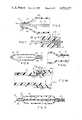
- FIG. 1shows a simplified plan view of an IAB embodying the principles of the present invention.
- FIG. 2shows an enlarged sectional view of the distal end portion of the IAB of FIG. 1.
- FIG. 2ashows one manner for modifying the structure shown in FIG. 2 for eliminating spurious signals.
- FIG. 3shows a sectional view of another alternative embodiment of the present invention.
- FIG. 4shows an end view of the EKG electrode employed in the alternative embodiment of FIG. 3.
- FIG. 5shows the manner in which the stylet may be coupled to external monitoring and control circuitry.
- FIGS. 6 and 7show sectional views of still another preferred embodiment of the present invention.
- FIG. 8shows still another preferred embodiment of the present invention for coupling an electrode positioned adjacent to the proximal end of the balloon to EKG monitoring equipment.
- FIG. 8ashows a detailed view of the electrical coupling between the electrode and the coupling conductor of FIG. 8.
- FIG. 8bshows a detailed view of one preferred arrangement for coupling the proximal end of the coupling conductor FIG. 8 to EKG monitoring equipment.
- FIG. 9shows another manner for modifying the structure shown in FIG. 2 for eliminating spurious signals.
- FIG. 1shows an IAB 10 designed in accordance with the principles of the present invention and which is of the type described in the aforementioned copending application Ser. No. 253,680.
- IAB 10is comprised of a balloon 12 having a tapered distal end 12a terminating in tip 14 and having a tapered proximal end 12b joined with and communicating with the distal ends 16a of catheter tube 16, whose proximal end 16b is joined with and communicates with coupling unit 18.
- Coupling unit 18is provided with a through bore 18a and a branch bore 18b.
- a stylet 20has its distal end joined to or coupled with tip 14. Stylet 20 extends rearwardly through balloon 12 and catheter tube 16 and extends into the through bore 18a of coupling unit 18 and is joined with operating handle 22. The end 20b of stylet 20 extends beyond operating handle 22 for coupling to monitoring and control circuitry as will be more fully described.
- Branch bore 18bcommunicates with through-bore 18a and hence with catheter tube 16 for providing a path for receiving positive and negative pulsatile pressure pulses for respectively inflating and deflating ballon 12.
- An additional tube 24may be provided for coupling branch bore 18b to the pressure operating source (not shown).
- operating handle 22is rotated in a first direction as shown by arrow A.
- Operating handle 22is secured to threaded member 26 (by set screw 34) which in turn has an enlarged head portion 28 whose left-hand end is coupled to stylet 20.
- Rotation of operating handle 22 in the direction shown by arrow Acauses member 26 and stylet 20 to rotate in the same direction, thereby causing the distal end 12a of balloon 12 to be twisted and, hence, wrapped about style 20 significantly reducing the outer diameter of the balloon when fully wrapped.
- the balloon 12is preferably fully wrapped when control member 22 bears against the end 18c of coupling member 18.
- a gasket member 22amay provide an airtight seal between coupling member 18 and control member 22 when the balloon 12 is fully wrapped about stylet 20.
- the balloon 12is then inserted into the body preferably through a percutaneous technique.
- the balloon 12is untwisted by rotating operating member 22 in the reverse direction as shown by arrow B.
- the balloon 12is untwisted when the diagonal shoulder 28a of enlarged head portion 28 bears against the interior wall 18d of coupling member 18, which also provides an air-tight seal.
- the distal end 20a of stylet 20is electrically coupled to a cup-shaped electrode 30 embodied within the tip portion 14 of the IAB 10.
- the tapered portion 12a of balloon 12is formed of an insulating plastic material, terminates in the tip portion 14 and subtantially completely covers electrode 30 except for a small portion 14a which exposes electrode 30.
- the distal end 20a of stylet 20is preferably coupled to electrode 30 through suitable means such as, for example, a soldered joint 32. Any other suitable electrical and mechanical coupling arrangement may be employed.
- Stylet 20extends rearwardly, as was previously described, and is electrically connected to conductive member 26 which extends through operating handle 22, and is secured against movement or rotation relative to operating handle 22 by set screw 34.
- the right-hand end 26a of member 26extends beyond operating handle 22 as shown, and is adapted for electrical coupling with electrical connector clip 36 whose free ends 36a and 36b of arms 36c and 36d respectively grip right-hand end 26a and maintain this firm gripping condition under the control of biasing spring 38.
- electrical connector clip 36is provided with a cooperating hinge and electrical coupling arrangement 36e for electrical coupling with a wire 40 for connection with control and monitoring circuitry (not shown for purposes of simplicity), which may, for example, be a display monitor and control circuitry for recognizing the R wave of an EKG signal for controlling the timing of balloon pumping.
- control and monitoring circuitrymay, for example, be a display monitor and control circuitry for recognizing the R wave of an EKG signal for controlling the timing of balloon pumping.
- the remaining electrode for establishing a complete electrical pathmay be coupled in the conventional way, i.e. by mounting the remaining electrode (not shown) in the chest region of the patient and providing conductor means between the remaining electrode and the monitoring and control circuitry.
- FIG. 2a and FIG. 9show a slightly modified arrangement 10' for that shown in FIG. 2 wherein stylet 20 is covered with an insulating film 21 to prevent a "weak" electrical signal derived from distal end 14 and coupled from electrode 30' to stylet 20 from picking up interference from conductive fluids which may be present within balloon 12 and/or catheter 16.
- conductive fluidswhich may be present within balloon 12 and/or catheter 16.
- Such fluidsare transmitted through the balloon membrane 12 from the patient by a "reverse osmosis" process.
- These fluidsare often conductive and generate a signal as they are sloshed around within the interior of balloon 12 and/or catheter 16, due either to the expansion and/or collapse of the balloon or the movement of the gases causes inflation and deflation of the balloon.
- FIGS. 3 and 4show an alternative embodiment of the present invention in which the electrode may be arranged in the region of the proximal end 12b of balloon 12.
- the electrode 42comprises an annular conductive ring embedded within the catheter tube 16 which may be provided with a groove 16c about its interior periphery for receiving and positioning electrode 42.
- a pair of arcuate-shaped conductive leaf spring members 44 and 46have their ends arranged within recesses 42a through 42d arranged at spaced intervals about the inner periphery of electrode 42.
- Each of the conductive leaf spring members 44 and 46is provided with a semi-circular shaped central portion 44a, 46a which semi-circular shaped portions cooperate to form a circular-shaped portion for receiving stylet 20 which makes wiping engagement with the conductive leaf spring members 44 and 46 while, at the same time, being capable of rotation about its longitudinal axis and movement in the axial direction either to the left or to the right, as shown by arrows A1 and B1 due to rotation of operating member 22 and hence threaded member 26 in the rotational directions A and B respectively.
- an electrically conductive pathis provided between stylet 20 and electrode 42 through conductive leaf springs 44 and 46. Similar to the embodiment shown in FIG. 2, a portion 16d of catheter tube 16 is removed to expose a portion of electrode 42. Electrical connection between electrode 42 and stylet 20 is established in the same manner as is shown in FIG. 5 wherein stylet 20 is electrically connected, preferably by soldering or similar mechanical and electrical joining technique, to head portion 28 which may be coupled to external monitoring and control circuitry through electrical coupling clip 36 and electrical wire 40.
- FIGS. 6 and 7show another alternative embodiment 50 of the present invention wherein like elements as between the previous figures and FIGS. 6 and 7 are designated by like numerals.
- a hollow, flexible, elongated tube 52of a diameter which is appreciably smaller than the inner diameter of catheter tube 16.
- a pair of wires 54 and 56 embedded within the wall of tube 52are arranged in helical patterns of first and second opposite senses. At least one of said wires (or both if desired) are connected to electrode 30 at the distal end 52a of tube 52, establishing an electrical path between EKG electrode 30 and one or both of said conductive wires 54 and 56. Opening 14a in the insulation layer covering electrode 30 establishes electrical contact with the blood in the aortic arch.
- proximal end 52b of tube 52is coupled to one end of enlarged member 28 and at least one of the proximal ends of wires 54 and 56 are electrically connected to conductive member 28, thus establishing an electrical path from electrode 30 through one or both wires 54 and 56 to member 26 whose right-hand end 26a extends beyond the right-hand end of operating knob 22 for coupling with an electrical connecting clip such as the clip assembly 36 shown in FIG. 5.
- Rotation of operating knob 22serves to rotate elongated tube 52 for twisting and wrapping balloon 12 about the stylet member 52.
- the balloonis now ready for insertion, preferably through a percutaneous technique.
- operating knob 22is rotated in the reverse direction to untwist balloon 12 in readiness for assisting the heart in the pumping of blood.
- Monitoring and control of the heart and the pumping functionis established by coupling electrode 30 through conductors 54 (and/or 56) to monitoring and control circuitry in the same manner as was previously described with respect to the embodiments of FIGS. 1 through 5.
- member 26is provided with a through bore 26b which communicates with the hollow interior of tube 52 to permit pressure monitoring, insertion of a separate independent probe and for other monitoring or treatment purposes.
- tip 14is provided with an open end 14b with the insulating cover communicating with the distal end of tube 52, as shown best in FIG. 12, providing fluid-tight isolation between the interior of tube 52 and the interior of balloon 12.
- the electrode 42 shown in FIG. 3may be coupled to EKG monitoring apparatus through an arrangement different from that shown in FIG. 3 and, more specifically, as shown in FIGS. 8 through 8b.
- electrode 42is shown arranged adjacent to the proximal tapered end 12b of balloon 12, and surrounding that portion of catheter tube 16 adjacent to tapered end 12b, the catheter 16 is provided with an electrical conductor 17 embodied within the wall of catheter 16 and extending along the length of catheter 16 and preferably substantially parallel to the longitudinal axis of catheter 16.
- a portion of the catheter wall 16is removed to form a wedge-shaped groove 19 through which conductor 17 extends.
- the wedge-shaped groove 19is filled with a conductive epoxy 21 which fills the wedge-shaped groove 19 and electrically couples electrode 42 to conductor 17.
- Electrode 42may be exposed or covered with an insulation layer, as shown in FIG. 3.
- FIG. 8bshows the proximal end of catheter 16 extending into the hollow interior 23a of a coupling member 23, having a shallow peripheral recess 23b for receiving a cylindrical-shaped conductive member 25.
- a radially aligned electrode 27extends through the wall of coupling 23 with its lower end 27a electrically connected to conductive cylinder 25 and so that its upper end 27a extends beyond the outer periphery 23c of the coupling 23, and is available for electrical connection to an EKG monitoring device, for example.
- a wedge-shaped groove 16eis formed in catheter tube 16 and is of a depth sufficient to expose at least a portion of conductor 17.
- the wedge-shaped groove 16eis filled with a conductive epoxy 29, which electrically couples conductor 17 to conductive cylinder 25.
- the end 27a of electrode 27is also preferably coupled to conductive ring 25 by a layer of conductive epoxy 31 positioned between end 27a of electrode 27 and the exterior periphery of conductive cylinder 25.
- the continuous conductive pathextends from electrode 42 through conductor 17 embedded within the wall of catheter 16, conductive epoxy 29, conductive cylinder 25, and conductive epoxy 31 to electrode 27 which may be coupled to monitoring equipment such as an EKG monitor.
- the stylet 20may be utilized to couple an electrode arranged in the balloon tip, as shown in FIG. 2, in which the end 20a of stylet 20 is electrically coupled to conductive electrode 30.
- the electrode arrangements shown in FIGS. 2 and 8into an intra-aortic balloon assembly, it is possible to provide a pair of EKG electrodes arranged within the body of the patient, and thereby totally eliminate the need for an external EKG electrode, which is necessary in the event that only one of the techniques shown in FIGS. 2 and 8 is incorporated into an intra-aortic balloon assembly.
Landscapes
- Health & Medical Sciences (AREA)
- Heart & Thoracic Surgery (AREA)
- Engineering & Computer Science (AREA)
- Life Sciences & Earth Sciences (AREA)
- Cardiology (AREA)
- General Health & Medical Sciences (AREA)
- Veterinary Medicine (AREA)
- Biomedical Technology (AREA)
- Public Health (AREA)
- Animal Behavior & Ethology (AREA)
- Anesthesiology (AREA)
- Hematology (AREA)
- Mechanical Engineering (AREA)
- Vascular Medicine (AREA)
- Physics & Mathematics (AREA)
- Medical Informatics (AREA)
- Biophysics (AREA)
- Pathology (AREA)
- Molecular Biology (AREA)
- Surgery (AREA)
- Transplantation (AREA)
- Geometry (AREA)
- Media Introduction/Drainage Providing Device (AREA)
Abstract
Description
The present invention relates to intra-aortic balloons and more particularly to intra-aortic balloons adapted for percutaneous insertion and having a twisting stylet which provides the additional function of establishing an electrical path from the electrode to instrumentation external to the body.
Intra-aortic balloons (IAB's) are utilized to assist a weakened heart in the blood pumping function. The intra-aortic balloon is inserted into the body through the femoral artery for placement in the vicinity of the aortic arch. Since the femoral artery has a narrow diameter, it is important to provide a balloon having the smallest possible profile to facilitate entry and placement of the IAB. This has been accomplished through the development of the twistable balloon such as, for example, that described in copending application Ser. No.: 253,680 filed Apr. 13, 1981; which has matured into U.S. Pat. No. 4,422,477, dated Dec. 27, 1983. The intra-aortic balloon described in the abovementioned copending application is provided with an elongated stylet and operating means positioned external to the body for twisting the stylet in order to twist the balloon and cause it to be wrapped about the stylet, thereby significantly reducing the profile of the balloon and greatly facilitating its insertion into the femoral artery. Upon insertion and proper placement of the balloon, the operating means is rotated in the reverse direction causing the balloon to be untwisted and thereby placed in readiness for a balloon pumping operation.
The IAB is operated in synchronism with the operation of the weakened heart. In order to synchronize the operation of the IAB with the heart, it is conventional to employ an EKG signal which is derived by coupling a pair of electrodes, typically to the chest of the patient, which electrodes are coupled through conductors to an instrument which utilizes the R wave of an EKG for triggering balloon pumping. Instruments of this type also are provided with visual display means which make it possible to view the EKG signal and the balloon pumping signal to be assured of proper synchronism of the IAB with the heart and to monitor the progress of the balloon pumping operation.
The electrodes are typically coupled to the chest area of the patient. The electrical interface between the patient's body and the electrodes is of high resistivity, causing significant signal loss and erroneous signals through the interface. This decreases the integrity of the signal, and this condition is compounded by a weakened heart condition resulting in an EKG signal which is frequently insufficient for purposes of monitoring the heart and operating the IAB in synchronism with the pumping heart.
In addition, the "skin" electrodes are subject to erroneous signals complexes due to movement by the patient or disturbance of the electrodes by the medical procedure. These "false" signals may be incorrectly interpreted as "R-waves" and result in incorrect and harmful timing of the balloon.
The present invention is characterized by comprising an IAB which utilizes a stylet having an operating member for twisting the balloon to reduce the outer diameter of the balloon and thereby facilitate its insertion into the body through a percutaneous technique. The stylet is preferably formed of a conductive material or, alternatively, is formed of a material having a conductor embedded therein.
The distal tip of the IAB contains an electrode within a suitable insulating material formed of a plastic which is compatible with, and nontoxic to, the body. The distal end of the stylet is electrically connected to the electrode and the proximal end thereof extends through the balloon and catheter tube and is accessible at a location exterior to the body to facilitate electrical connection by means of a connector clip for coupling the electrode to monitoring and control circuitry. The stylet thus provides the dual functions of twisting and untwisting the balloon to facilitate percutaneous insertion and removal and balloon operation, respectively, and to provide means for electrical connection between an EKG electrode and monitoring and control circuitry. A small portion of the plastic material covering the electrode is removed, exposing the electrode to the body fluids (blood) which is sufficiently conductive to conduct the EKG signal from the heart through the blood and electrode and, hence, through the stylet to the monitoring and control instrumentation.
The EKG electrode carried by the IAB may be positioned either at the distal or proximal end of the balloon. The electrode next to the proximal end of the balloon may be coupled to the EKG electrode through a conductor embedded in the wall of the catheter. This arrangement may be used to eliminate the external electrode coupled to the chest of the patient.
It is, therefore, one object of the present invention to provide an IAB adapted for percutaneous insertion and having an EKG electrode and a stylet for twisting and untwisting the balloon and further for providing a high conductivity electrical path between the aforesaid EKG electrode and monitoring and control circuitry located external to the body.
Still another object of the present invention is to provide an IAB of the type described hereinabove and having a conductive stylet formed of a suitable metallic material.
Still another object of the present invention is to provide an IAB of the character described in which the stylet member is formed of an insulating material having a conductor embedded therein.
The above, as well as other objects of the present invention, will become apparent when reading the accompanying description and drawing in which:
FIG. 1 shows a simplified plan view of an IAB embodying the principles of the present invention.
FIG. 2 shows an enlarged sectional view of the distal end portion of the IAB of FIG. 1.
FIG. 2a shows one manner for modifying the structure shown in FIG. 2 for eliminating spurious signals. FIG. 3 shows a sectional view of another alternative embodiment of the present invention.
FIG. 4 shows an end view of the EKG electrode employed in the alternative embodiment of FIG. 3.
FIG. 5 shows the manner in which the stylet may be coupled to external monitoring and control circuitry.
FIGS. 6 and 7 show sectional views of still another preferred embodiment of the present invention.
FIG. 8 shows still another preferred embodiment of the present invention for coupling an electrode positioned adjacent to the proximal end of the balloon to EKG monitoring equipment.
FIG. 8a shows a detailed view of the electrical coupling between the electrode and the coupling conductor of FIG. 8.
FIG. 8b shows a detailed view of one preferred arrangement for coupling the proximal end of the coupling conductor FIG. 8 to EKG monitoring equipment.
FIG. 9 shows another manner for modifying the structure shown in FIG. 2 for eliminating spurious signals.
FIG. 1 shows an IAB 10 designed in accordance with the principles of the present invention and which is of the type described in the aforementioned copending application Ser. No. 253,680. IAB 10 is comprised of aballoon 12 having a tapereddistal end 12a terminating intip 14 and having a tapered proximal end 12b joined with and communicating with thedistal ends 16a ofcatheter tube 16, whoseproximal end 16b is joined with and communicates withcoupling unit 18.
Considering FIGS. 1 and 5 and assuming it is desired to prepareIAB 10 for insertion into the femoral artery,operating handle 22 is rotated in a first direction as shown by arrow A.Operating handle 22 is secured to threaded member 26 (by set screw 34) which in turn has an enlargedhead portion 28 whose left-hand end is coupled to stylet 20. Rotation ofoperating handle 22 in the direction shown by arrow Acauses member 26 and stylet 20 to rotate in the same direction, thereby causing thedistal end 12a ofballoon 12 to be twisted and, hence, wrapped aboutstyle 20 significantly reducing the outer diameter of the balloon when fully wrapped. Theballoon 12 is preferably fully wrapped whencontrol member 22 bears against the end 18c ofcoupling member 18. Agasket member 22a may provide an airtight seal betweencoupling member 18 andcontrol member 22 when theballoon 12 is fully wrapped aboutstylet 20.
Theballoon 12 is then inserted into the body preferably through a percutaneous technique. When properly inserted and positioned, theballoon 12 is untwisted by rotatingoperating member 22 in the reverse direction as shown by arrow B. Theballoon 12 is untwisted when the diagonal shoulder 28a ofenlarged head portion 28 bears against the interior wall 18d ofcoupling member 18, which also provides an air-tight seal.
As shown in FIG. 2, thedistal end 20a ofstylet 20 is electrically coupled to a cup-shapedelectrode 30 embodied within thetip portion 14 of theIAB 10. The taperedportion 12a ofballoon 12 is formed of an insulating plastic material, terminates in thetip portion 14 and subtantially completely coverselectrode 30 except for asmall portion 14a which exposeselectrode 30. Thedistal end 20a ofstylet 20 is preferably coupled toelectrode 30 through suitable means such as, for example, a soldered joint 32. Any other suitable electrical and mechanical coupling arrangement may be employed.
It should be understood that the remaining electrode for establishing a complete electrical path may be coupled in the conventional way, i.e. by mounting the remaining electrode (not shown) in the chest region of the patient and providing conductor means between the remaining electrode and the monitoring and control circuitry.
FIG. 2a and FIG. 9 show a slightly modified arrangement 10' for that shown in FIG. 2 whereinstylet 20 is covered with an insulatingfilm 21 to prevent a "weak" electrical signal derived fromdistal end 14 and coupled from electrode 30' to stylet 20 from picking up interference from conductive fluids which may be present withinballoon 12 and/orcatheter 16. Such fluids are transmitted through theballoon membrane 12 from the patient by a "reverse osmosis" process. These fluids are often conductive and generate a signal as they are sloshed around within the interior ofballoon 12 and/orcatheter 16, due either to the expansion and/or collapse of the balloon or the movement of the gases causes inflation and deflation of the balloon.
FIGS. 3 and 4 show an alternative embodiment of the present invention in which the electrode may be arranged in the region of the proximal end 12b ofballoon 12. As shown in FIG. 3, theelectrode 42 comprises an annular conductive ring embedded within thecatheter tube 16 which may be provided with agroove 16c about its interior periphery for receiving andpositioning electrode 42. A pair of arcuate-shaped conductiveleaf spring members recesses 42a through 42d arranged at spaced intervals about the inner periphery ofelectrode 42. Each of the conductiveleaf spring members central portion 44a, 46a which semi-circular shaped portions cooperate to form a circular-shaped portion for receivingstylet 20 which makes wiping engagement with the conductiveleaf spring members member 22 and hence threadedmember 26 in the rotational directions A and B respectively.
Thus, an electrically conductive path is provided betweenstylet 20 andelectrode 42 throughconductive leaf springs catheter tube 16 is removed to expose a portion ofelectrode 42. Electrical connection betweenelectrode 42 andstylet 20 is established in the same manner as is shown in FIG. 5 whereinstylet 20 is electrically connected, preferably by soldering or similar mechanical and electrical joining technique, to headportion 28 which may be coupled to external monitoring and control circuitry throughelectrical coupling clip 36 andelectrical wire 40.
FIGS. 6 and 7 show anotheralternative embodiment 50 of the present invention wherein like elements as between the previous figures and FIGS. 6 and 7 are designated by like numerals. In place ofstylet 20, there is provided a hollow, flexible,elongated tube 52 of a diameter which is appreciably smaller than the inner diameter ofcatheter tube 16. To prevent torsional forces from twistinghollow tube 52, a pair ofwires tube 52 are arranged in helical patterns of first and second opposite senses. At least one of said wires (or both if desired) are connected to electrode 30 at the distal end 52a oftube 52, establishing an electrical path betweenEKG electrode 30 and one or both of saidconductive wires Opening 14a in the insulationlayer covering electrode 30 establishes electrical contact with the blood in the aortic arch.
The proximal end 52b oftube 52 is coupled to one end ofenlarged member 28 and at least one of the proximal ends ofwires conductive member 28, thus establishing an electrical path fromelectrode 30 through one or bothwires member 26 whose right-hand end 26a extends beyond the right-hand end of operatingknob 22 for coupling with an electrical connecting clip such as theclip assembly 36 shown in FIG. 5.
Rotation of operatingknob 22 serves to rotateelongated tube 52 for twisting and wrappingballoon 12 about thestylet member 52. The balloon is now ready for insertion, preferably through a percutaneous technique.
After insertion and proper placement of the balloon within the aortic arch, operatingknob 22 is rotated in the reverse direction to untwistballoon 12 in readiness for assisting the heart in the pumping of blood. Monitoring and control of the heart and the pumping function is established by couplingelectrode 30 through conductors 54 (and/or 56) to monitoring and control circuitry in the same manner as was previously described with respect to the embodiments of FIGS. 1 through 5.
As an additional capability,member 26 is provided with a through bore 26b which communicates with the hollow interior oftube 52 to permit pressure monitoring, insertion of a separate independent probe and for other monitoring or treatment purposes. In order to accomplish this function,tip 14 is provided with anopen end 14b with the insulating cover communicating with the distal end oftube 52, as shown best in FIG. 12, providing fluid-tight isolation between the interior oftube 52 and the interior ofballoon 12.
Theelectrode 42 shown in FIG. 3 may be coupled to EKG monitoring apparatus through an arrangement different from that shown in FIG. 3 and, more specifically, as shown in FIGS. 8 through 8b. Althoughelectrode 42 is shown arranged adjacent to the proximal tapered end 12b ofballoon 12, and surrounding that portion ofcatheter tube 16 adjacent to tapered end 12b, thecatheter 16 is provided with anelectrical conductor 17 embodied within the wall ofcatheter 16 and extending along the length ofcatheter 16 and preferably substantially parallel to the longitudinal axis ofcatheter 16. A portion of thecatheter wall 16 is removed to form a wedge-shaped groove 19 through whichconductor 17 extends. The wedge-shaped groove 19 is filled with aconductive epoxy 21 which fills the wedge-shaped groove 19 and electrically couples electrode 42 toconductor 17.Electrode 42 may be exposed or covered with an insulation layer, as shown in FIG. 3.
FIG. 8b shows the proximal end ofcatheter 16 extending into the hollow interior 23a of acoupling member 23, having a shallowperipheral recess 23b for receiving a cylindrical-shapedconductive member 25. A radially aligned electrode 27 extends through the wall ofcoupling 23 with itslower end 27a electrically connected toconductive cylinder 25 and so that itsupper end 27a extends beyond theouter periphery 23c of thecoupling 23, and is available for electrical connection to an EKG monitoring device, for example.
A wedge-shapedgroove 16e is formed incatheter tube 16 and is of a depth sufficient to expose at least a portion ofconductor 17. The wedge-shapedgroove 16e is filled with a conductive epoxy 29, which electrically couplesconductor 17 toconductive cylinder 25. Theend 27a of electrode 27 is also preferably coupled toconductive ring 25 by a layer ofconductive epoxy 31 positioned betweenend 27a of electrode 27 and the exterior periphery ofconductive cylinder 25.
Thus, as can be seen from FIGS. 8 through 8b, the continuous conductive path extends fromelectrode 42 throughconductor 17 embedded within the wall ofcatheter 16, conductive epoxy 29,conductive cylinder 25, andconductive epoxy 31 to electrode 27 which may be coupled to monitoring equipment such as an EKG monitor.
Using the arrangement shown in FIGS. 8 through 8b, thestylet 20 may be utilized to couple an electrode arranged in the balloon tip, as shown in FIG. 2, in which theend 20a ofstylet 20 is electrically coupled toconductive electrode 30. By incorporating the electrode arrangements shown in FIGS. 2 and 8 into an intra-aortic balloon assembly, it is possible to provide a pair of EKG electrodes arranged within the body of the patient, and thereby totally eliminate the need for an external EKG electrode, which is necessary in the event that only one of the techniques shown in FIGS. 2 and 8 is incorporated into an intra-aortic balloon assembly.
A latitude of modification, change and substitution is intended in the foregoing disclosure, and in some instances some features of the invention will be employed without a corresponding use of other features. Accordingly, it is appropriate that the appended claims be construed broadly and in a manner consistent with the spirit and scope of the invention herein.
Claims (21)
1. An intra-aortic balloon assembly comprising:
an inflatable balloon formed of a nonstretchable plastic material and having a distal end terminating in a tip and having an open proximal end;
an elongated catheter tube having an open distal end communicating with and air-tightly joined to the open proximal end of said balloon, and having a proximal end for receiving positive and negative pressure pulses for selectively inflating and deflating said balloon;
a flexible elongated conductive stylet extending from said balloon distal end and through said balloon and said catheter tube and accessible at the proximal end of said catheter tube and being rotatable about its longitudinal axis to rotate said tip and said balloon to wrap said balloon about said stylet when rotated in a first direction and to unwrap said balloon from said stylet when rotated in the opposite direction;
said tip containing a conductive electrode, the distal end of said stylet being electrically connected to said electrode;
said tip including insulation means covering said electrode and having at least a portion thereof removed to expose a portion of the surface of said electrode;
means coupled to the proximal end of said stylet for coupling the electrical condition at said electrode to an output utilization device.
2. The intra-aortic balloon assembly of claim 1, wherein said stylet is an elongated conductive wire.
3. The intra-aortic balloon assembly of claim 1, wherein said stylet is an elongated hollow tubular conductive member.
4. The intra-aortic balloon assembly of claim 1, wherein said stylet is an elongated hollow tubular member formed of an insulating material and having a conductive wire embedded in the wall thereof;
one end of said wire being connected to the electrode arranged in said tip and the other end being electrically connected to said coupling means.
5. The intra-aortic balloon assembly of claim 4, wherein said wire is arranged in a helical fashion in the wall of said tubular member.
6. The intra-aortic balloon assembly of claim 4, wherein said wire is substantially parallel to the longitudinal axis of said hollow tubular member.
7. The intra-aortic balloon assembly of claim 1, wherein said stylet is an elongated conductive wire covered with a film of insulation material to insulate said wire from conductive fluids, which may be present within the interior of the balloon and catheter tube of said intra-aortic balloon assembly.
8. The intra-aortic balloon assembly of claim 1, wherein said coupling means is further characterized as being fixedly mounted upon the proximal end of said catheter tube and having manually rotatable means rotatable relative to said coupling means and being connected to the proximal end of said stylet for selectively rotating said stylet in a first and second direction;
said manually rotatable means including a conductive member having a first end extending into said coupling means and joined to the proximal end of said stylet, and having a second end extending outwardly from said coupling means, and having at least a portion thereof exposed for coupling with an external utilization means.
9. The intra-aortic balloon assembly of claim 8, wherein said manually rotatable means includes a knob formed of an insulating material;
said conductive member extending through said knob and means on said knob for securing said knob to said conductive member.
10. The intra-aortic balloon assembly of claim 9, wherein said coupling means has a threaded opening for receiving said conductive member;
said conductive member threadedly engaging said threaded opening.
11. An intra-aortic balloon assembly comprising:
an inflatable balloon formed of a nonstretchable plastic material and having a distal end terminating in a tip and having an open proximal end;
an elongated catheter tube having an open distal end communicating with and air-tightly joined to the open proximal end of said balloon, and having a proximal end for receiving positive and negative pressure pulses for selectively inflating and deflating said balloon;
a flexible elongated conductive stylet extending from said balloon distal end through said balloon and said catheter tube and accessible at the proximal end of said catheter tube and being rotatable about its longitudinal axis to rotate said tip and said balloon to wrap said balloon about said stylet when rotated in a first direction and to unwrap said balloon from said stylet when rotated in the opposite direction;
an electrode encircling a portion of the catheter tube at a location adjacent the proximal end of the balloon and means arranged within said electrode for electrically connecting said electrode to said stylet;
insulation means covering said electrode having at least a portion thereof removed to expose a portion of the surface of said electrode;
means coupled to the proximal end of said stylet for coupling the electrical condition at said electrode to an output utilization device.
12. The intra-aortic balloon assembly of claim 11, wherein said electrode is a cylindrical-shaped conductive shell;
said connecting means comprising resilient conductive biasing members joined to said conductive shell and wipingly engaging said stylet for establishing an electrical path from said electrode through said biasing members to said stylet.
13. The intra-aortic balloon assembly of claim 11, wherein said electrode is a cylindrical-shaped conductive shell;
said connecting means comprising a pair of arcuate-shaped resilient conductive members having their outer ends joined to the inner periphery of said conductive shell;
the central portion of said arcuate-shaped members having a semi-circular shaped configuration and being arranged so that said semi-circular portions cooperatively define a substantially circular-shaped opening through which the stylet extends, said arcuate-shaped members making continuous wiping engagement with said stylet to establish an electrical path between said stylet and said electrode.
14. The intra-aortic balloon assembly of claim 13, wherein said catheter tube substantially completely covers said electrode to define said insulation means;
a portion of said catheter tube wall being removed to expose a portion of the conductive shell positioned therebeneath.
15. An intra-aortic balloon assembly comprising:
an inflatable balloon formed of a non-stretchable plastic material and having a distal end terminating in a tip and having an open proximal end;
an elongated catheter tube having an open distal end communicating with and air-tightly joined to the open proximal end of said balloon, and having a proximal end for receiving positive and negative pressure pulses for selectively inflating and deflating said balloon;
a flexible elongated conductive stylet extending from said balloon distal end through said balloon and said catheter tube and accessible at the proximal end of said catheter tube and being rotatable about its longitudinal axis to rotate said tip and said balloon to wrap said balloon about said stylet when rotated in a first direction and to unwrap said balloon from said stylet when rotated in the opposite direction;
said tip containing a first conductive electrode, the distal end of said stylet being electrically connected to said first electrode;
said tip including insulation means covering said first electrode having at least a portion thereof removed to expose a portion of the surface of said first electrode;
a second electrode arranged along said catheter tube at a location adjacent to the proximal end of said balloon;
first coupling means arranged at the proximal end of said stylet for coupling the electrical condition at said first electrode to an output utilization device;
a conductor embedded in the wall of said catheter tube having a distal end adjacent to said second electrode and a proximal end arranged adjacent to the proximal end of said catheter tube;
second coupling means for electrically coupling said second electrode to the distal end of said conductor;
a third coupling electrode; and
third coupling means for electrically connecting the proximal end of said conductor to said third electrode.
16. The intra-aortic balloon assembly of claim 15, wherein said catheter tube is provided with a groove along its exterior periphery and extending into the catheter tube wall to a depth sufficient to expose the distal end of the conductor; and
said second coupling means comprising conductive epoxy means being provided in said groove and engaging said conductor and said second electrode for establishing an electrical path therebetween.
17. The intra-aortic balloon assembly of claim 15, wherein the exterior periphery of said catheter tube is provided with a groove, said groove having a depth sufficient to expose the proximal end of the conductor; and
said third coupling means including conductive epoxy means provided in said groove for electrically connecting said conductor and said third coupling electrode.
18. The intra-aortic balloon assembly of claim 15, wherein said stylet is a tubular member.
19. The intra-aortic balloon assembly of claim 18, wherein said tubular member is conductive.
20. The intra-aortic balloon assembly of claim 18, wherein said tubular member is formed of a plastic material having a conductor embedded in the wall of said tubular member;
said tubular member conductor being electrically connected between said first electrode in said tip and said first coupling means.
21. An intra-aortic balloon assembly comprising:
an inflatable balloon formed of a nonstretchable plastic material and having a distal end terminating in a tip and having an open proximal end;
an elongated catheter tube having an open distal end communicating with and air-tightly joined to the open proximal end of said balloon, and having a proximal end for receiving positive and negative pressure pulses for selectively inflating and deflating said balloon;
a flexible elongated conductive stylet extending from said balloon distal end through said balloon and said catheter tube and accessible at the proximal end of said catheter tube, and being rotatable about its longitudinal axis to rotate said tip and said balloon to wrap said balloon about said stylet when rotated in a first direction, and to unwrap said balloon from said stylet when rotated in the opposite direction;
said tip containing a conductive electrode electrically connected to the distal end of said stylet, said tip having at least a portion thereof removed to expose a portion of the surface of said electrode;
means coupled to the proximal end of said stylet for coupling the electrical condition at said electrode to an output utilization device;
a conductor embedded in the wall of said catheter tube;
a second electrode arranged on said catheter tube adjacent to said balloon;
conductive epoxy means electrically connecting said conductor to said second electrode;
a coupling member joined to the proximal end of said catheter tube;
said coupling member having a connecting electrode;
conductive epoxy means electrically connecting said conductor to said connecting electrode.
Priority Applications (1)
| Application Number | Priority Date | Filing Date | Title |
|---|---|---|---|
| US06/481,323US4552127A (en) | 1983-04-01 | 1983-04-01 | Percutaneous intra-aortic balloon having an EKG electrode and a twisting stylet for coupling the EKG electrode to monitoring and/or pacing instrumentation external to the body |
Applications Claiming Priority (1)
| Application Number | Priority Date | Filing Date | Title |
|---|---|---|---|
| US06/481,323US4552127A (en) | 1983-04-01 | 1983-04-01 | Percutaneous intra-aortic balloon having an EKG electrode and a twisting stylet for coupling the EKG electrode to monitoring and/or pacing instrumentation external to the body |
Publications (1)
| Publication Number | Publication Date |
|---|---|
| US4552127Atrue US4552127A (en) | 1985-11-12 |
Family
ID=23911515
Family Applications (1)
| Application Number | Title | Priority Date | Filing Date |
|---|---|---|---|
| US06/481,323Expired - LifetimeUS4552127A (en) | 1983-04-01 | 1983-04-01 | Percutaneous intra-aortic balloon having an EKG electrode and a twisting stylet for coupling the EKG electrode to monitoring and/or pacing instrumentation external to the body |
Country Status (1)
| Country | Link |
|---|---|
| US (1) | US4552127A (en) |
Cited By (69)
| Publication number | Priority date | Publication date | Assignee | Title |
|---|---|---|---|---|
| US4655748A (en)* | 1984-09-04 | 1987-04-07 | Aisin Seiki Kabushikikaisha | Cannula for infusion of fluid |
| US4692148A (en)* | 1986-03-28 | 1987-09-08 | Aisin Seiki Kabushiki Kaisha | Intra-aortic balloon pump apparatus and method of using same |
| WO1988000844A1 (en)* | 1986-08-08 | 1988-02-11 | Scimed Life Systems, Inc. | Angioplasty dilating guide wire |
| US4729384A (en)* | 1985-07-08 | 1988-03-08 | Jacques Chevallier | Balloon assembly for esophageal probe |
| US4733652A (en)* | 1985-12-31 | 1988-03-29 | Aisin Seiki Kabushiki Kaisha | Intra-aortic balloon |
| US4809681A (en)* | 1986-03-28 | 1989-03-07 | Aisin Seiki Kabushiki Kaisha | Electrocardiographic measurement method for controlling an intra-aortic balloon pump |
| US4861330A (en)* | 1987-03-12 | 1989-08-29 | Gene Voss | Cardiac assist device and method |
| US4957110A (en)* | 1989-03-17 | 1990-09-18 | C. R. Bard, Inc. | Steerable guidewire having electrodes for measuring vessel cross-section and blood flow |
| US4968300A (en)* | 1988-10-05 | 1990-11-06 | Abiomed Limited Partnership | Balloon stretch mechanism |
| US5035694A (en)* | 1989-05-15 | 1991-07-30 | Advanced Cardiovascular Systems, Inc. | Dilatation catheter assembly with heated balloon |
| US5087246A (en)* | 1988-12-29 | 1992-02-11 | C. R. Bard, Inc. | Dilation catheter with fluted balloon |
| US5090957A (en)* | 1988-10-05 | 1992-02-25 | Abiomed, Inc. | Intraaortic balloon insertion |
| US5114423A (en)* | 1989-05-15 | 1992-05-19 | Advanced Cardiovascular Systems, Inc. | Dilatation catheter assembly with heated balloon |
| EP0486979A1 (en)* | 1990-11-21 | 1992-05-27 | B. Braun Melsungen AG | Guiding probe |
| US5184621A (en)* | 1991-05-29 | 1993-02-09 | C. R. Bard, Inc. | Steerable guidewire having electrodes for measuring vessel cross-section and blood flow |
| US5205822A (en)* | 1991-06-10 | 1993-04-27 | Cordis Corporation | Replaceable dilatation catheter |
| US5255678A (en)* | 1991-06-21 | 1993-10-26 | Ecole Polytechnique | Mapping electrode balloon |
| US5277201A (en)* | 1992-05-01 | 1994-01-11 | Vesta Medical, Inc. | Endometrial ablation apparatus and method |
| US5290232A (en)* | 1991-06-10 | 1994-03-01 | Cordis Corporation | Replaceable dilatation catheter |
| US5354276A (en)* | 1993-03-18 | 1994-10-11 | Applied Medical Resources Corporation | Internal mammary artery catheter and method |
| US5411027A (en)* | 1992-07-03 | 1995-05-02 | Wiklund; Lars | Equipment and method for treating circulatory arrest |
| US5443470A (en)* | 1992-05-01 | 1995-08-22 | Vesta Medical, Inc. | Method and apparatus for endometrial ablation |
| US5489277A (en)* | 1991-05-17 | 1996-02-06 | Act Medical, Inc. | Device having a radiopaque marker for endoscopic accessories and method of making same |
| US5499980A (en)* | 1988-08-08 | 1996-03-19 | Scimed Life Systems, Inc. | Polyimide balloon catheter and method of making same |
| US5522834A (en)* | 1992-10-15 | 1996-06-04 | Applied Medical Resources Corporation | Internal mammary artery catheter and method |
| US5562720A (en)* | 1992-05-01 | 1996-10-08 | Vesta Medical, Inc. | Bipolar/monopolar endometrial ablation device and method |
| US5593419A (en)* | 1990-06-18 | 1997-01-14 | C.R. Bard, Inc. | Fixed wire dilatation catheter with distal twistable segment |
| DE29601310U1 (en)* | 1996-01-26 | 1997-06-05 | B. Braun Melsungen Ag, 34212 Melsungen | Catheter set with ECG lead possibility |
| US5665103A (en)* | 1996-03-07 | 1997-09-09 | Scimed Life Systems, Inc. | Stent locating device |
| US5928193A (en)* | 1997-10-03 | 1999-07-27 | Boston Scientific Corporation | Balloon catheterization |
| EP0988827A1 (en)* | 1998-09-23 | 2000-03-29 | B. Braun Melsungen Ag | Connector device for an intra-atrial ECG lead |
| US20020128536A1 (en)* | 2001-03-12 | 2002-09-12 | Arie Zigler | Centering mechanism for probe |
| US20030009119A1 (en)* | 2001-03-23 | 2003-01-09 | Kamm Roger D. | Method and apparatus for stimulating angiogenesis and wound healing by use of external compression |
| US6669624B2 (en) | 2002-03-26 | 2003-12-30 | O. Howard Frazier | Temporary heart-assist system |
| US20080058758A1 (en)* | 2006-08-31 | 2008-03-06 | Medrad, Inc. | Method for delivering therapeutic agents |
| US20100262225A1 (en)* | 2007-12-12 | 2010-10-14 | Peter Schneider | Device and method for tacking plaque to a blood vessel wall |
| US7937148B2 (en) | 2005-10-14 | 2011-05-03 | Nanostim, Inc. | Rate responsive leadless cardiac pacemaker |
| US20110190712A1 (en)* | 2010-01-29 | 2011-08-04 | C.R. Bard, Inc. | Sacrificial catheter |
| JP2012034852A (en)* | 2010-08-06 | 2012-02-23 | Japan Lifeline Co Ltd | Electrode catheter |
| US20120220891A1 (en)* | 2001-07-11 | 2012-08-30 | Nuvasive, Inc. | System and Methods for Determining Nerve Proximity, Direction, and Pathology During Surgery |
| US20130030426A1 (en)* | 2011-07-28 | 2013-01-31 | Diana Gallardo | Integrated ablation system using catheter with multiple irrigation lumens |
| US20130184515A1 (en)* | 2006-04-24 | 2013-07-18 | Yoel Ovil | Double balloon pump cardiac assist device and related method of use |
| US8527068B2 (en) | 2009-02-02 | 2013-09-03 | Nanostim, Inc. | Leadless cardiac pacemaker with secondary fixation capability |
| US8543205B2 (en) | 2010-10-12 | 2013-09-24 | Nanostim, Inc. | Temperature sensor for a leadless cardiac pacemaker |
| US8540618B2 (en) | 2003-01-31 | 2013-09-24 | L-Vad Technology, Inc. | Stable aortic blood pump implant |
| US8548579B2 (en) | 2001-09-25 | 2013-10-01 | Nuvasive, Inc. | System and methods for performing surgical procedures and assessments |
| US8615310B2 (en) | 2010-12-13 | 2013-12-24 | Pacesetter, Inc. | Delivery catheter systems and methods |
| US9020611B2 (en) | 2010-10-13 | 2015-04-28 | Pacesetter, Inc. | Leadless cardiac pacemaker with anti-unscrewing feature |
| US9060692B2 (en) | 2010-10-12 | 2015-06-23 | Pacesetter, Inc. | Temperature sensor for a leadless cardiac pacemaker |
| US9126032B2 (en) | 2010-12-13 | 2015-09-08 | Pacesetter, Inc. | Pacemaker retrieval systems and methods |
| US9168383B2 (en) | 2005-10-14 | 2015-10-27 | Pacesetter, Inc. | Leadless cardiac pacemaker with conducted communication |
| US9242102B2 (en) | 2010-12-20 | 2016-01-26 | Pacesetter, Inc. | Leadless pacemaker with radial fixation mechanism |
| US9492190B2 (en) | 2011-02-09 | 2016-11-15 | Covidien Lp | Tissue dissectors |
| US9511236B2 (en) | 2011-11-04 | 2016-12-06 | Pacesetter, Inc. | Leadless cardiac pacemaker with integral battery and redundant welds |
| US9545322B2 (en) | 2007-12-12 | 2017-01-17 | Intact Vascular, Inc. | Device and method for tacking plaque to blood vessel wall |
| US9603730B2 (en) | 2007-12-12 | 2017-03-28 | Intact Vascular, Inc. | Endoluminal device and method |
| US9694122B2 (en)* | 2003-01-31 | 2017-07-04 | L-Vad Technology, Inc. | Rigid body aortic blood pump implant |
| US20170189059A1 (en)* | 2016-01-06 | 2017-07-06 | Boston Scientific Scimed, Inc. | Percutaneous access device |
| US9730818B2 (en) | 2007-12-12 | 2017-08-15 | Intact Vascular, Inc. | Endoluminal device and method |
| US9802054B2 (en) | 2012-08-01 | 2017-10-31 | Pacesetter, Inc. | Biostimulator circuit with flying cell |
| US10022250B2 (en) | 2007-12-12 | 2018-07-17 | Intact Vascular, Inc. | Deployment device for placement of multiple intraluminal surgical staples |
| US10166127B2 (en) | 2007-12-12 | 2019-01-01 | Intact Vascular, Inc. | Endoluminal device and method |
| US10245167B2 (en) | 2015-01-29 | 2019-04-02 | Intact Vascular, Inc. | Delivery device and method of delivery |
| US10271973B2 (en) | 2011-06-03 | 2019-04-30 | Intact Vascular, Inc. | Endovascular implant |
| US10278839B2 (en) | 2007-12-12 | 2019-05-07 | Intact Vascular, Inc. | Endovascular impant |
| US10898356B2 (en) | 2015-01-29 | 2021-01-26 | Intact Vascular, Inc. | Delivery device and method of delivery |
| US10993824B2 (en) | 2016-01-01 | 2021-05-04 | Intact Vascular, Inc. | Delivery device and method of delivery |
| US11660218B2 (en) | 2017-07-26 | 2023-05-30 | Intact Vascular, Inc. | Delivery device and method of delivery |
| US11771491B2 (en) | 2015-12-30 | 2023-10-03 | Schuler Scientific Solutions, Llc | Tissue mapping and treatment |
Citations (10)
| Publication number | Priority date | Publication date | Assignee | Title |
|---|---|---|---|---|
| US3568660A (en)* | 1967-11-20 | 1971-03-09 | Battelle Development Corp | Pacemaker catheter |
| US3707960A (en)* | 1970-09-03 | 1973-01-02 | Us Health | Balloon cardiac assisting pump having intraaortic electrocardiographic electrodes |
| US3837347A (en)* | 1972-04-20 | 1974-09-24 | Electro Catheter Corp | Inflatable balloon-type pacing probe |
| US4073287A (en)* | 1976-04-05 | 1978-02-14 | American Medical Systems, Inc. | Urethral profilometry catheter |
| US4106512A (en)* | 1976-12-16 | 1978-08-15 | Medtronic, Inc. | Transvenously implantable lead |
| WO1980002231A1 (en)* | 1979-04-24 | 1980-10-30 | J Donachy | Long-life flexible electrode lead |
| WO1981002110A1 (en)* | 1980-01-30 | 1981-08-06 | T Fogarty | Dilatation catheter apparatus and method |
| US4349031A (en)* | 1980-03-07 | 1982-09-14 | The Kendall Company | Esophageal probe with disposable cover |
| US4362150A (en)* | 1980-09-10 | 1982-12-07 | Kontron Cardiovascular Inc. | Percutaneous intra-aortic balloon apparatus |
| US4362166A (en)* | 1980-11-04 | 1982-12-07 | Mallinckrodt, Inc. | Disposable medical probe and connector |
- 1983
- 1983-04-01USUS06/481,323patent/US4552127A/ennot_activeExpired - Lifetime
Patent Citations (10)
| Publication number | Priority date | Publication date | Assignee | Title |
|---|---|---|---|---|
| US3568660A (en)* | 1967-11-20 | 1971-03-09 | Battelle Development Corp | Pacemaker catheter |
| US3707960A (en)* | 1970-09-03 | 1973-01-02 | Us Health | Balloon cardiac assisting pump having intraaortic electrocardiographic electrodes |
| US3837347A (en)* | 1972-04-20 | 1974-09-24 | Electro Catheter Corp | Inflatable balloon-type pacing probe |
| US4073287A (en)* | 1976-04-05 | 1978-02-14 | American Medical Systems, Inc. | Urethral profilometry catheter |
| US4106512A (en)* | 1976-12-16 | 1978-08-15 | Medtronic, Inc. | Transvenously implantable lead |
| WO1980002231A1 (en)* | 1979-04-24 | 1980-10-30 | J Donachy | Long-life flexible electrode lead |
| WO1981002110A1 (en)* | 1980-01-30 | 1981-08-06 | T Fogarty | Dilatation catheter apparatus and method |
| US4349031A (en)* | 1980-03-07 | 1982-09-14 | The Kendall Company | Esophageal probe with disposable cover |
| US4362150A (en)* | 1980-09-10 | 1982-12-07 | Kontron Cardiovascular Inc. | Percutaneous intra-aortic balloon apparatus |
| US4362166A (en)* | 1980-11-04 | 1982-12-07 | Mallinckrodt, Inc. | Disposable medical probe and connector |
Cited By (133)
| Publication number | Priority date | Publication date | Assignee | Title |
|---|---|---|---|---|
| US4655748A (en)* | 1984-09-04 | 1987-04-07 | Aisin Seiki Kabushikikaisha | Cannula for infusion of fluid |
| US4729384A (en)* | 1985-07-08 | 1988-03-08 | Jacques Chevallier | Balloon assembly for esophageal probe |
| US4733652A (en)* | 1985-12-31 | 1988-03-29 | Aisin Seiki Kabushiki Kaisha | Intra-aortic balloon |
| US4692148A (en)* | 1986-03-28 | 1987-09-08 | Aisin Seiki Kabushiki Kaisha | Intra-aortic balloon pump apparatus and method of using same |
| US4809681A (en)* | 1986-03-28 | 1989-03-07 | Aisin Seiki Kabushiki Kaisha | Electrocardiographic measurement method for controlling an intra-aortic balloon pump |
| WO1988000844A1 (en)* | 1986-08-08 | 1988-02-11 | Scimed Life Systems, Inc. | Angioplasty dilating guide wire |
| US4861330A (en)* | 1987-03-12 | 1989-08-29 | Gene Voss | Cardiac assist device and method |
| US5499980A (en)* | 1988-08-08 | 1996-03-19 | Scimed Life Systems, Inc. | Polyimide balloon catheter and method of making same |
| US4968300A (en)* | 1988-10-05 | 1990-11-06 | Abiomed Limited Partnership | Balloon stretch mechanism |
| US5090957A (en)* | 1988-10-05 | 1992-02-25 | Abiomed, Inc. | Intraaortic balloon insertion |
| US5087246A (en)* | 1988-12-29 | 1992-02-11 | C. R. Bard, Inc. | Dilation catheter with fluted balloon |
| US4957110A (en)* | 1989-03-17 | 1990-09-18 | C. R. Bard, Inc. | Steerable guidewire having electrodes for measuring vessel cross-section and blood flow |
| US5114423A (en)* | 1989-05-15 | 1992-05-19 | Advanced Cardiovascular Systems, Inc. | Dilatation catheter assembly with heated balloon |
| US5035694A (en)* | 1989-05-15 | 1991-07-30 | Advanced Cardiovascular Systems, Inc. | Dilatation catheter assembly with heated balloon |
| US5593419A (en)* | 1990-06-18 | 1997-01-14 | C.R. Bard, Inc. | Fixed wire dilatation catheter with distal twistable segment |
| EP0486979A1 (en)* | 1990-11-21 | 1992-05-27 | B. Braun Melsungen AG | Guiding probe |
| US5243995A (en)* | 1990-11-21 | 1993-09-14 | B. Braun Melsungen Ag | Guide probe and clamping bushing for ecg controlled positioning |
| US5489277A (en)* | 1991-05-17 | 1996-02-06 | Act Medical, Inc. | Device having a radiopaque marker for endoscopic accessories and method of making same |
| US5184621A (en)* | 1991-05-29 | 1993-02-09 | C. R. Bard, Inc. | Steerable guidewire having electrodes for measuring vessel cross-section and blood flow |
| US5290232A (en)* | 1991-06-10 | 1994-03-01 | Cordis Corporation | Replaceable dilatation catheter |
| US5205822A (en)* | 1991-06-10 | 1993-04-27 | Cordis Corporation | Replaceable dilatation catheter |
| US5255678A (en)* | 1991-06-21 | 1993-10-26 | Ecole Polytechnique | Mapping electrode balloon |
| US5443470A (en)* | 1992-05-01 | 1995-08-22 | Vesta Medical, Inc. | Method and apparatus for endometrial ablation |
| US5277201A (en)* | 1992-05-01 | 1994-01-11 | Vesta Medical, Inc. | Endometrial ablation apparatus and method |
| US5562720A (en)* | 1992-05-01 | 1996-10-08 | Vesta Medical, Inc. | Bipolar/monopolar endometrial ablation device and method |
| US5411027A (en)* | 1992-07-03 | 1995-05-02 | Wiklund; Lars | Equipment and method for treating circulatory arrest |
| US5522834A (en)* | 1992-10-15 | 1996-06-04 | Applied Medical Resources Corporation | Internal mammary artery catheter and method |
| US5354276A (en)* | 1993-03-18 | 1994-10-11 | Applied Medical Resources Corporation | Internal mammary artery catheter and method |
| EP0786266A1 (en) | 1996-01-26 | 1997-07-30 | B. Braun Melsungen Ag | Catheter set with ECG monitoring lead capability |
| DE29601310U1 (en)* | 1996-01-26 | 1997-06-05 | B. Braun Melsungen Ag, 34212 Melsungen | Catheter set with ECG lead possibility |
| US5665103A (en)* | 1996-03-07 | 1997-09-09 | Scimed Life Systems, Inc. | Stent locating device |
| US5928193A (en)* | 1997-10-03 | 1999-07-27 | Boston Scientific Corporation | Balloon catheterization |
| US6135982A (en)* | 1997-10-03 | 2000-10-24 | Boston Scientific Corporation | Balloon catheterization |
| US6517514B1 (en) | 1997-10-03 | 2003-02-11 | Boston Scientific Corporation | Balloon catheterization |
| EP0988827A1 (en)* | 1998-09-23 | 2000-03-29 | B. Braun Melsungen Ag | Connector device for an intra-atrial ECG lead |
| US6733439B2 (en)* | 2001-03-12 | 2004-05-11 | Apti Inc. | Centering mechanism for probe |
| US20020128536A1 (en)* | 2001-03-12 | 2002-09-12 | Arie Zigler | Centering mechanism for probe |
| US20030009119A1 (en)* | 2001-03-23 | 2003-01-09 | Kamm Roger D. | Method and apparatus for stimulating angiogenesis and wound healing by use of external compression |
| US9037250B2 (en) | 2001-07-11 | 2015-05-19 | Nuvasive, Inc. | System and methods for determining nerve proximity, direction and pathology during surgery |
| US8812116B2 (en)* | 2001-07-11 | 2014-08-19 | Nuvasive, Inc. | System and methods for determining nerve proximity, direction, and pathology during surgery |
| US20120220891A1 (en)* | 2001-07-11 | 2012-08-30 | Nuvasive, Inc. | System and Methods for Determining Nerve Proximity, Direction, and Pathology During Surgery |
| US8768450B2 (en) | 2001-09-25 | 2014-07-01 | Nuvasive, Inc. | System and methods for performing surgical procedures and assessments |
| US8738123B2 (en) | 2001-09-25 | 2014-05-27 | Nuvasive, Inc. | System and methods for performing surgical procedures and assessments |
| US8548579B2 (en) | 2001-09-25 | 2013-10-01 | Nuvasive, Inc. | System and methods for performing surgical procedures and assessments |
| US6669624B2 (en) | 2002-03-26 | 2003-12-30 | O. Howard Frazier | Temporary heart-assist system |
| US9694122B2 (en)* | 2003-01-31 | 2017-07-04 | L-Vad Technology, Inc. | Rigid body aortic blood pump implant |
| US9433715B2 (en) | 2003-01-31 | 2016-09-06 | L-Vad Technology, Inc. | Stable aortic blood pump implant |
| US8540618B2 (en) | 2003-01-31 | 2013-09-24 | L-Vad Technology, Inc. | Stable aortic blood pump implant |
| US8788053B2 (en) | 2005-10-14 | 2014-07-22 | Pacesetter, Inc. | Programmer for biostimulator system |
| US8788035B2 (en) | 2005-10-14 | 2014-07-22 | Pacesetter, Inc. | Leadless cardiac pacemaker triggered by conductive communication |
| US8352025B2 (en) | 2005-10-14 | 2013-01-08 | Nanostim, Inc. | Leadless cardiac pacemaker triggered by conductive communication |
| US10238883B2 (en) | 2005-10-14 | 2019-03-26 | Pacesetter Inc. | Leadless cardiac pacemaker system for usage in combination with an implantable cardioverter-defibrillator |
| US9872999B2 (en) | 2005-10-14 | 2018-01-23 | Pacesetter, Inc. | Leadless cardiac pacemaker system for usage in combination with an implantable cardioverter-defibrillator |
| US8457742B2 (en) | 2005-10-14 | 2013-06-04 | Nanostim, Inc. | Leadless cardiac pacemaker system for usage in combination with an implantable cardioverter-defibrillator |
| US9072913B2 (en) | 2005-10-14 | 2015-07-07 | Pacesetter, Inc. | Rate responsive leadless cardiac pacemaker |
| US9409033B2 (en) | 2005-10-14 | 2016-08-09 | Pacesetter, Inc. | Leadless cardiac pacemaker system for usage in combination with an implantable cardioverter-defibrillator |
| US9358400B2 (en) | 2005-10-14 | 2016-06-07 | Pacesetter, Inc. | Leadless cardiac pacemaker |
| US8295939B2 (en) | 2005-10-14 | 2012-10-23 | Nanostim, Inc. | Programmer for biostimulator system |
| US9227077B2 (en) | 2005-10-14 | 2016-01-05 | Pacesetter, Inc. | Leadless cardiac pacemaker triggered by conductive communication |
| US9687666B2 (en) | 2005-10-14 | 2017-06-27 | Pacesetter, Inc. | Leadless cardiac pacemaker system for usage in combination with an implantable cardioverter-defibrillator |
| US9216298B2 (en) | 2005-10-14 | 2015-12-22 | Pacesetter, Inc. | Leadless cardiac pacemaker system with conductive communication |
| US9192774B2 (en) | 2005-10-14 | 2015-11-24 | Pacesetter, Inc. | Cardiac pacemaker system for usage in combination with an implantable cardioverter-defibrillator |
| US8010209B2 (en)* | 2005-10-14 | 2011-08-30 | Nanostim, Inc. | Delivery system for implantable biostimulator |
| US8855789B2 (en) | 2005-10-14 | 2014-10-07 | Pacesetter, Inc. | Implantable biostimulator delivery system |
| US7937148B2 (en) | 2005-10-14 | 2011-05-03 | Nanostim, Inc. | Rate responsive leadless cardiac pacemaker |
| US9168383B2 (en) | 2005-10-14 | 2015-10-27 | Pacesetter, Inc. | Leadless cardiac pacemaker with conducted communication |
| US8798745B2 (en) | 2005-10-14 | 2014-08-05 | Pacesetter, Inc. | Leadless cardiac pacemaker system for usage in combination with an implantable cardioverter-defibrillator |
| US7945333B2 (en) | 2005-10-14 | 2011-05-17 | Nanostim, Inc. | Programmer for biostimulator system |
| US8784292B2 (en)* | 2006-04-24 | 2014-07-22 | Yoel Ovil | Double balloon pump cardiac assist device and related method of use |
| US20130184515A1 (en)* | 2006-04-24 | 2013-07-18 | Yoel Ovil | Double balloon pump cardiac assist device and related method of use |
| US8876754B2 (en) | 2006-08-31 | 2014-11-04 | Bayer Medical Care Inc. | Catheter with filtering and sensing elements |
| US20080058758A1 (en)* | 2006-08-31 | 2008-03-06 | Medrad, Inc. | Method for delivering therapeutic agents |
| US10799374B2 (en) | 2007-12-12 | 2020-10-13 | Intact Vascular, Inc. | Device and method for tacking plaque to blood vessel wall |
| US10022250B2 (en) | 2007-12-12 | 2018-07-17 | Intact Vascular, Inc. | Deployment device for placement of multiple intraluminal surgical staples |
| US10278839B2 (en) | 2007-12-12 | 2019-05-07 | Intact Vascular, Inc. | Endovascular impant |
| US10166127B2 (en) | 2007-12-12 | 2019-01-01 | Intact Vascular, Inc. | Endoluminal device and method |
| US10299945B2 (en) | 2007-12-12 | 2019-05-28 | Intact Vascular, Inc. | Method of treating atherosclerotic occlusive disease |
| US10660771B2 (en) | 2007-12-12 | 2020-05-26 | Intact Vacsular, Inc. | Deployment device for placement of multiple intraluminal surgical staples |
| US9730818B2 (en) | 2007-12-12 | 2017-08-15 | Intact Vascular, Inc. | Endoluminal device and method |
| US8128677B2 (en)* | 2007-12-12 | 2012-03-06 | Intact Vascular LLC | Device and method for tacking plaque to a blood vessel wall |
| US10117762B2 (en) | 2007-12-12 | 2018-11-06 | Intact Vascular, Inc. | Endoluminal device and method |
| US9603730B2 (en) | 2007-12-12 | 2017-03-28 | Intact Vascular, Inc. | Endoluminal device and method |
| US10835395B2 (en) | 2007-12-12 | 2020-11-17 | Intact Vascular, Inc. | Method of treating atherosclerotic occlusive disease |
| US9545322B2 (en) | 2007-12-12 | 2017-01-17 | Intact Vascular, Inc. | Device and method for tacking plaque to blood vessel wall |
| US20100262225A1 (en)* | 2007-12-12 | 2010-10-14 | Peter Schneider | Device and method for tacking plaque to a blood vessel wall |
| US10188533B2 (en) | 2007-12-12 | 2019-01-29 | Intact Vascular, Inc. | Minimal surface area contact device for holding plaque to blood vessel wall |
| US9974670B2 (en) | 2007-12-12 | 2018-05-22 | Intact Vascular, Inc. | Method of treating atherosclerotic occlusive disease |
| US8527068B2 (en) | 2009-02-02 | 2013-09-03 | Nanostim, Inc. | Leadless cardiac pacemaker with secondary fixation capability |
| US9272155B2 (en) | 2009-02-02 | 2016-03-01 | Pacesetter, Inc. | Leadless cardiac pacemaker with secondary fixation capability |
| USRE50564E1 (en) | 2009-02-02 | 2025-09-02 | Pacesetter, Inc. | Leadless cardiac pacemaker with secondary fixation capability |
| US10888443B2 (en) | 2009-06-11 | 2021-01-12 | Intact Vascular, Inc. | Device for holding plaque to blood vessel wall |
| US10779971B2 (en) | 2009-06-11 | 2020-09-22 | Intact Vascular, Inc. | Endovascular implant |
| US8864745B2 (en)* | 2010-01-29 | 2014-10-21 | C. R. Bard, Inc. | Sacrificial catheter |
| US20130030413A1 (en)* | 2010-01-29 | 2013-01-31 | C. R. Bard, Inc. | Sacrificial Catheter |
| US9610424B2 (en) | 2010-01-29 | 2017-04-04 | C. R. Bard, Inc. | Sacrificial catheter |
| US20110190712A1 (en)* | 2010-01-29 | 2011-08-04 | C.R. Bard, Inc. | Sacrificial catheter |
| US9950140B2 (en) | 2010-01-29 | 2018-04-24 | C. R. Bard, Inc. | Sacrificial catheter |
| CN102821676A (en)* | 2010-01-29 | 2012-12-12 | C·R·巴德股份有限公司 | Sacrificial catheter |
| CN102821676B (en)* | 2010-01-29 | 2016-09-07 | C·R·巴德股份有限公司 | sacrificial catheter |
| US8764728B2 (en)* | 2010-01-29 | 2014-07-01 | C. R. Bard, Inc. | Sacrificial catheter |
| US10137013B2 (en) | 2010-05-29 | 2018-11-27 | Intact Vascular, Inc. | Endoluminal device and method |
| US10779968B2 (en) | 2010-05-29 | 2020-09-22 | Intact Vascular, Inc. | Endoluminal device and method |
| JP2012034852A (en)* | 2010-08-06 | 2012-02-23 | Japan Lifeline Co Ltd | Electrode catheter |
| US9687655B2 (en) | 2010-10-12 | 2017-06-27 | Pacesetter, Inc. | Temperature sensor for a leadless cardiac pacemaker |
| US9060692B2 (en) | 2010-10-12 | 2015-06-23 | Pacesetter, Inc. | Temperature sensor for a leadless cardiac pacemaker |
| US8543205B2 (en) | 2010-10-12 | 2013-09-24 | Nanostim, Inc. | Temperature sensor for a leadless cardiac pacemaker |
| US9020611B2 (en) | 2010-10-13 | 2015-04-28 | Pacesetter, Inc. | Leadless cardiac pacemaker with anti-unscrewing feature |
| US9126032B2 (en) | 2010-12-13 | 2015-09-08 | Pacesetter, Inc. | Pacemaker retrieval systems and methods |
| US11759234B2 (en) | 2010-12-13 | 2023-09-19 | Pacesetter, Inc. | Pacemaker retrieval systems and methods |
| US12226122B2 (en) | 2010-12-13 | 2025-02-18 | Pacesetter, Inc. | Pacemaker retrieval systems and methods |
| US10188425B2 (en) | 2010-12-13 | 2019-01-29 | Pacesetter, Inc. | Pacemaker retrieval systems and methods |
| US11890032B2 (en) | 2010-12-13 | 2024-02-06 | Pacesetter, Inc. | Pacemaker retrieval systems and methods |
| US11786272B2 (en) | 2010-12-13 | 2023-10-17 | Pacesetter, Inc. | Pacemaker retrieval systems and methods |
| US8615310B2 (en) | 2010-12-13 | 2013-12-24 | Pacesetter, Inc. | Delivery catheter systems and methods |
| US9242102B2 (en) | 2010-12-20 | 2016-01-26 | Pacesetter, Inc. | Leadless pacemaker with radial fixation mechanism |
| US9492190B2 (en) | 2011-02-09 | 2016-11-15 | Covidien Lp | Tissue dissectors |
| US10285831B2 (en) | 2011-06-03 | 2019-05-14 | Intact Vascular, Inc. | Endovascular implant |
| US10390977B2 (en) | 2011-06-03 | 2019-08-27 | Intact Vascular, Inc. | Endovascular implant |
| US10271973B2 (en) | 2011-06-03 | 2019-04-30 | Intact Vascular, Inc. | Endovascular implant |
| US10779969B2 (en) | 2011-06-03 | 2020-09-22 | Intact Vascular, Inc. | Endovascular implant and deployment devices |
| US10743932B2 (en)* | 2011-07-28 | 2020-08-18 | Biosense Webster (Israel) Ltd. | Integrated ablation system using catheter with multiple irrigation lumens |
| US20130030426A1 (en)* | 2011-07-28 | 2013-01-31 | Diana Gallardo | Integrated ablation system using catheter with multiple irrigation lumens |
| US9511236B2 (en) | 2011-11-04 | 2016-12-06 | Pacesetter, Inc. | Leadless cardiac pacemaker with integral battery and redundant welds |
| US9802054B2 (en) | 2012-08-01 | 2017-10-31 | Pacesetter, Inc. | Biostimulator circuit with flying cell |
| US10744332B2 (en) | 2012-08-01 | 2020-08-18 | Pacesetter, Inc. | Biostimulator circuit with flying cell |
| US10898356B2 (en) | 2015-01-29 | 2021-01-26 | Intact Vascular, Inc. | Delivery device and method of delivery |
| US11304836B2 (en) | 2015-01-29 | 2022-04-19 | Intact Vascular, Inc. | Delivery device and method of delivery |
| US10245167B2 (en) | 2015-01-29 | 2019-04-02 | Intact Vascular, Inc. | Delivery device and method of delivery |
| US11771491B2 (en) | 2015-12-30 | 2023-10-03 | Schuler Scientific Solutions, Llc | Tissue mapping and treatment |
| US12004805B2 (en) | 2015-12-30 | 2024-06-11 | Schuler Scientific Solutions, Llc | Tissue mapping and treatment |
| US10993824B2 (en) | 2016-01-01 | 2021-05-04 | Intact Vascular, Inc. | Delivery device and method of delivery |
| US20170189059A1 (en)* | 2016-01-06 | 2017-07-06 | Boston Scientific Scimed, Inc. | Percutaneous access device |
| US11660218B2 (en) | 2017-07-26 | 2023-05-30 | Intact Vascular, Inc. | Delivery device and method of delivery |
Similar Documents
| Publication | Publication Date | Title |
|---|---|---|
| US4552127A (en) | Percutaneous intra-aortic balloon having an EKG electrode and a twisting stylet for coupling the EKG electrode to monitoring and/or pacing instrumentation external to the body | |
| US4304239A (en) | Esophageal probe with balloon electrode | |
| US4444195A (en) | Cardiac lead having multiple ring electrodes | |
| US4072154A (en) | Sealing arrangement for heart pacer electrode leads | |
| US4280503A (en) | Bipolar electrode insertion apparatus | |
| US4930521A (en) | Variable stiffness esophageal catheter | |
| US3516412A (en) | Bipolar electrode having irregularity at inserting end thereof and method of insertion | |
| US4236525A (en) | Multiple function lead assembly | |
| US3472234A (en) | Body organ electrode | |
| USRE34502E (en) | Steerable catheter | |
| US4777955A (en) | Left ventricle mapping probe | |
| US5490323A (en) | Method for making a body implantable sensor | |
| US5179952A (en) | Electrocardial stimulator probe | |
| US3367339A (en) | Implantable nerve stimulating electrode and lead | |
| US4458695A (en) | Multipolar electrode assembly for pacing lead | |
| US5545201A (en) | Bipolar active fixation lead for sensing and pacing the heart | |
| USRE31990E (en) | Multiple function lead assembly and method for inserting assembly into an implantable tissue stimulator | |
| GB1424262A (en) | Disposable central venous catheter | |
| JPS6190677A (en) | Guide catheter and heart pace making method using the same | |
| US20040143284A1 (en) | Subxiphoid procedures and apparatus for placement of cardiac defibrillator and pacer | |
| JPH06205842A (en) | Lead assembly for implantable medical device | |
| GB1337670A (en) | Electrode for atrial pacing | |
| US4517984A (en) | Esophageal probe | |
| EP0646388A1 (en) | Electrode device | |
| JPH06190060A (en) | Implantable medical device connector assembly |
Legal Events
| Date | Code | Title | Description |
|---|---|---|---|
| AS | Assignment | Owner name:IABP CORPORATION A DE CORP Free format text:ASSIGNMENT OF ASSIGNORS INTEREST.;ASSIGNOR:SCHIFF PETER;REEL/FRAME:004445/0504 Effective date:19850731 | |
| STCF | Information on status: patent grant | Free format text:PATENTED CASE | |
| FEPP | Fee payment procedure | Free format text:PAYOR NUMBER ASSIGNED (ORIGINAL EVENT CODE: ASPN); ENTITY STATUS OF PATENT OWNER: LARGE ENTITY Free format text:PAT HLDR NO LONGER CLAIMS SMALL ENT STAT AS INDIV INVENTOR (ORIGINAL EVENT CODE: LSM1); ENTITY STATUS OF PATENT OWNER: LARGE ENTITY | |
| FPAY | Fee payment | Year of fee payment:4 | |
| FPAY | Fee payment | Year of fee payment:8 | |
| SULP | Surcharge for late payment | ||
| FPAY | Fee payment | Year of fee payment:12 | |
| AS | Assignment | Owner name:ARROW INTERVENTIONAL, INC., PENNSYLVANIA Free format text:ASSIGNMENT OF ASSIGNORS INTEREST;ASSIGNOR:IABP CORPORATION;REEL/FRAME:008907/0760 Effective date:19971105 |