US4551061A - Flexible, extensible robot arm - Google Patents
Flexible, extensible robot armDownload PDFInfo
- Publication number
- US4551061A US4551061AUS06/485,654US48565483AUS4551061AUS 4551061 AUS4551061 AUS 4551061AUS 48565483 AUS48565483 AUS 48565483AUS 4551061 AUS4551061 AUS 4551061A
- Authority
- US
- United States
- Prior art keywords
- tubes
- fluid
- tube
- ribs
- sleeve
- Prior art date
- Legal status (The legal status is an assumption and is not a legal conclusion. Google has not performed a legal analysis and makes no representation as to the accuracy of the status listed.)
- Expired - Fee Related
Links
Images


Classifications
- B—PERFORMING OPERATIONS; TRANSPORTING
- B25—HAND TOOLS; PORTABLE POWER-DRIVEN TOOLS; MANIPULATORS
- B25J—MANIPULATORS; CHAMBERS PROVIDED WITH MANIPULATION DEVICES
- B25J18/00—Arms
- B25J18/06—Arms flexible
Definitions
- the inventionrelates to robot arms, and more particularly to a flexible and extensible arm.
- robot arms of the prior artare rigid. Rigidity is desired for lifting loads having substantial mass and, it has been tought, for accurate positioning of the arm.
- Most prior art robot armsrely on motors for accurate movement of arm joints.
- robot armsare formed by a plurality of rigid links connected by joints with motors changing positions of the links, usually by means of gears attached to the links at the joints.
- exterior hydraulic pistons and cylindershave been used to change the position of one link relative to another link in much the same way as linkages appearing on other industrial equipment, such as earth moving equipment and farm machinery.
- the most recent robot arms developedutilize servo controlled stepper motors for precise positioning of arm links.
- Another object of the inventionwas to devise a non-rigid or semi-rigid robot arm which could bend or extend on command.
- a robot armformed of a plurality of parallel, elongated adjacent elastomeric tubes which form a tube bundle.
- One end of the tube bundleis adapted for connection to a gripper while the opposite end has an interface for control circuitry.
- the elastomeric tubesare supplied with differential fluid pressure, pneumatic or hydraulic, to force bending.
- the tubesare maintained in parallel alignment by means of spaced apart parallel ribs, formed by disks, through which the tubes pass.
- the ribsform a framework for supporting the tubes, as well for supporting an outer covering for the arm.
- the elastomeric tubesmay be constrained against radial expansion by means of helical springs disposed about the tubes.
- the springsprevent outward bulging of the tubes.
- a plurality of flexible rodsextend through guide holes in the periphery of the ribs and are fixed at the gripper end of the tube bundle.
- the rodsmay be inserted into linear electronic position sensors such as an optical position encoder so that the rods, upon flexing of the arms, may be sensed and control circuitry may be provided to adjust differential pressure in the arm.
- Servo controlmay be provided using the transducers to generate a position signal which is combined with a command signal. The difference between the command and the position signals is an error signal which may be corrected by applying the proper amount of differential pressure.
- FIG. 1is a top plan view of the robot arm of the present invention with a gripper connected thereto.
- FIG. 2is a sectional view taken along lines 2--2 of FIG. 1 showing degrees of freedom of the robot arm.
- FIG. 3is a top, partially cut-away view of the robot arm of the present invention.
- FIG. 4is an end view taken along lines 4--4 of FIG. 3.
- FIG. 5is a detail of a tube terminating assembly illustrated in FIG. 4.
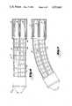
- FIG. 6is a top plan view of a robot arm of the present invention in a straight position.
- FIG. 7is a top plan view of the present invention in a flexed condition.
- the robot arm 11is shown, having a first end 13 connected to a gripper 15 and a second end 17 connected to a fluid pressure supply line 19.
- the armis extendible as indicated by dashed lines 21 upon application of a uniform amount of fluid pressure in each of the cylinders or can flex as indicated by the dashed lines 23a and 23b upon application of differential amounts of pressure.
- the range of motion of the arm 11is not limited to a single plane. Rather, the range is entirely variable, with possible positions indicated by the dashed lines 25a . . . 25h.
- the two flexed positions illustrated in FIG. 1can be achieved by providing two parallel, elongated elastomeric tubes in a tube bundle, with the two tubes maintained in parallel alignment. Then by supplying differential pressure to the two tubes, resembling thick-walled balloons, the motions shown in FIG. 1 may be achieved. If more than two tubes are provided, then a full range of motions, as illustrated in FIG. 1, may be achieved.
- FIG. 3shows a configuration having three parallel elastomeric tubes 31, 33 and 35. These tubes extend through a series of parallel ribs 41, 43, and 45. The tubes are approximately 1.5 centimeters in diameter and are fastened at a first end of the arm 13 in a manner described below. The opposite end of the tubes are secured at end 17 in a similar manner.
- the tubeshave helical springs 47 surrounding their outer surface to prevent radial expansion of the elastomeric tubes. Only lengthwise expansion is desired.
- the tube materialmay be sufficiently tough to resist radial expansion or springs may be provided as shown. In order to prevent radial expansion, the tubes may have helically wound fibers of polyester or similar material incorporated in the elastomeric material. This would eliminate the need for exterior springs.
- the ribs 41, 43, and 45have apertures, such as apertures 42, 44 and 46 defined therein. Since each of the ribs 41, 43 and 45 has apertures in corresponding locations, such apertures form a passageway for seating the elastomeric tubes.
- the passagewaysare generally parallel such that the tubes may be maintained in generally parallel alignment.
- Pressure lines 51, 53 and 55are connected to each of the tubes for introducing the proper amount of fluid pressure.
- a fluid supply sourcenot shown, independently supplies each of the lines 51, 53 and 55 under machine control.
- a plurality of flexible rods 61, 63 and 65is disposed about different radial positions of the arm.
- the rodsare fixed at end 13 by means of connection to rib 41.
- the rodspass through a linear position sensor 71, 73, and 75.
- the rodsare movable within the sensor with the amount of motion therein being converted into a digital electrical signal.
- the electrical signalmay then be used to gauge the amount of arm flexing or extension.
- the flexible rodsare placed at equi-angular peripheral regions of the arm.
- a fabric covering 57is disposed about the ribs 41, 43 and 45 about their circumferential periphery.
- the sleeveis to protect internal components from dirt and to give the arm a decorative outward appearance.
- the fabric sleevemay be supported directly on the ribs or may have its own framework consisting of a radial spring 59 slightly exceeding the circumference of the ribs. By providing a separate support structure, the sleeve may have radial dimples which tend to become taut on flexing.
- the rib 41is shown terminating tubes 31, 33 and 35.
- the rib 41is seen to be a round disk with radial structural reinforcement bosses 42a, 42b . . . 42f. Between these bosses are apertures, including apertures 32, 34 and 36, which partially define passageways for the tubes 31, 33 and 35 respectively. Additionally, apertures 62, 64 and 66 are provided to seat the flexible rods. In rib 41, the flexible rods are held in place with a fastener. In other ribs, the rod may pass therethrough being guided by a linear bearing in that place. Rib 41 also includes apertures 72, 74 and 76 which may allow passage or other control lines therethrough, such as fluid control lines for the robot gripper. Additionally, these apertures serve the function of lightening the weight of the ribs.
- FIG. 5illustrates the termination of a tube in a rib 45 at the second end of the robot arm.
- the tubehas an aperture 32a seating tube 31 and its encircling helical spring.
- a boltis seated in the tube which is locked in place by means of a nut 77.
- the shank 79 of the bolthas a central hole 81 drilled therein for allowing fluid pressure to be connected into the interior of the tube.
- a washer 83seals the end of the tube and rests against the spring. Washer 83 is pushed inwardly by tightening nut 77 and forms an expansion fluid seal against both the elastomeric tube material and the spring.
- Hole 81may be threaded to seat a hollow threaded adaptor which fits into these threads on one end and on another end connects to a fluid supply line.
- the flexible rod 61is shown extending through rib 45 through aperture 62. The operation of the rod is explained below.
- a robot arm 11having an interface 13 for mounting a gripper or other tool.
- transducers 71, 73 and 75are connected.
- the parallel rodsalso add rigidity to the flexible arm.
- the rodsare shown to extend the same amount into respective transducers.
- flexing of the armoccurs as illustrated in FIG. 7. This causes a change in position of the rods with rod 61 moving in the direction indicated by the arrow A, rod 63 moving in the direction indicated by arrow B, and rod 65 moving in the direction indicated by arrow C.
- LVDTlinear variable differential transformer
- the motion reported by transducers 71, 73 and 75represents the actual arm position.
- an armis directed to a particular target by means of a command signal. Any difference between the command signal and the reported actual position represents an error signal.
- the errormay be reduced to zero by means of a conventional closed loop servo system which is connected to the fluid control supply. Whenever an error is reported, fluid is injected or removed from appropriate tubes in order to correct arm position for zero positional error.
- a closed loop servo systemas described, an open loop system may also be used where the arm is merely directed to a desired position by providing needed amounts of fluid to the various tubes.
Landscapes
- Engineering & Computer Science (AREA)
- Robotics (AREA)
- Mechanical Engineering (AREA)
- Manipulator (AREA)
Abstract
Description
The invention relates to robot arms, and more particularly to a flexible and extensible arm.
Most robot arms of the prior art are rigid. Rigidity is desired for lifting loads having substantial mass and, it has been tought, for accurate positioning of the arm. Most prior art robot arms rely on motors for accurate movement of arm joints. Usually robot arms are formed by a plurality of rigid links connected by joints with motors changing positions of the links, usually by means of gears attached to the links at the joints. Alternatively, exterior hydraulic pistons and cylinders have been used to change the position of one link relative to another link in much the same way as linkages appearing on other industrial equipment, such as earth moving equipment and farm machinery. The most recent robot arms developed utilize servo controlled stepper motors for precise positioning of arm links.
There is a class of robot applications where a rigid arm is not desired. For example, in home uses a rigid arm could be dangerous, especially where small children are present. In other applications, where the object to be manipulated has very low mass, such as a wafer of the type used in integrated circuit fabrication, a rigid arm is simply not needed and could cause damage to a wafer in the event of a positioning error. Since a rigid arm is not intended to give, a positioning error could cause breakage of the wafer by causing it to bump into a fixed object. There is still another class of robots, which may be classified as toys or theatrical robots, which perform under computer control. These robots do not need rigid arms and might be dangerous if so equipped.
Another object of the invention was to devise a non-rigid or semi-rigid robot arm which could bend or extend on command.
The above object has been achieved in a robot arm formed of a plurality of parallel, elongated adjacent elastomeric tubes which form a tube bundle. One end of the tube bundle is adapted for connection to a gripper while the opposite end has an interface for control circuitry. The elastomeric tubes are supplied with differential fluid pressure, pneumatic or hydraulic, to force bending. The tubes are maintained in parallel alignment by means of spaced apart parallel ribs, formed by disks, through which the tubes pass. The ribs form a framework for supporting the tubes, as well for supporting an outer covering for the arm. When differential fluid pressure is applied to the tubes, the arm flexes. If pressure is uniformly increased, the arm extends.
The elastomeric tubes may be constrained against radial expansion by means of helical springs disposed about the tubes. The springs prevent outward bulging of the tubes.
A plurality of flexible rods extend through guide holes in the periphery of the ribs and are fixed at the gripper end of the tube bundle. At the opposite end of the tube bundle, the rods may be inserted into linear electronic position sensors such as an optical position encoder so that the rods, upon flexing of the arms, may be sensed and control circuitry may be provided to adjust differential pressure in the arm. Servo control may be provided using the transducers to generate a position signal which is combined with a command signal. The difference between the command and the position signals is an error signal which may be corrected by applying the proper amount of differential pressure.
FIG. 1 is a top plan view of the robot arm of the present invention with a gripper connected thereto.
FIG. 2 is a sectional view taken alonglines 2--2 of FIG. 1 showing degrees of freedom of the robot arm.
FIG. 3 is a top, partially cut-away view of the robot arm of the present invention.
FIG. 4 is an end view taken alonglines 4--4 of FIG. 3.
FIG. 5 is a detail of a tube terminating assembly illustrated in FIG. 4.
FIG. 6 is a top plan view of a robot arm of the present invention in a straight position.
FIG. 7 is a top plan view of the present invention in a flexed condition.
With reference to FIG. 1, the robot arm 11 is shown, having afirst end 13 connected to agripper 15 and asecond end 17 connected to a fluidpressure supply line 19. The arm is extendible as indicated bydashed lines 21 upon application of a uniform amount of fluid pressure in each of the cylinders or can flex as indicated by thedashed lines 23a and 23b upon application of differential amounts of pressure.
With reference to FIG. 2, the range of motion of the arm 11 is not limited to a single plane. Rather, the range is entirely variable, with possible positions indicated by thedashed lines 25a . . . 25h. The two flexed positions illustrated in FIG. 1 can be achieved by providing two parallel, elongated elastomeric tubes in a tube bundle, with the two tubes maintained in parallel alignment. Then by supplying differential pressure to the two tubes, resembling thick-walled balloons, the motions shown in FIG. 1 may be achieved. If more than two tubes are provided, then a full range of motions, as illustrated in FIG. 1, may be achieved.
FIG. 3 shows a configuration having three parallelelastomeric tubes parallel ribs arm 13 in a manner described below. The opposite end of the tubes are secured atend 17 in a similar manner. The tubes havehelical springs 47 surrounding their outer surface to prevent radial expansion of the elastomeric tubes. Only lengthwise expansion is desired. The tube material may be sufficiently tough to resist radial expansion or springs may be provided as shown. In order to prevent radial expansion, the tubes may have helically wound fibers of polyester or similar material incorporated in the elastomeric material. This would eliminate the need for exterior springs.
Theribs apertures ribs Pressure lines lines
In order to ascertain the amount of flexing of the robot arm, a plurality offlexible rods end 13 by means of connection to rib 41. At an opposite end, the rods pass through alinear position sensor
A fabric covering 57, resembling a sleeve, is disposed about theribs radial spring 59 slightly exceeding the circumference of the ribs. By providing a separate support structure, the sleeve may have radial dimples which tend to become taut on flexing.
With reference to FIG. 4, therib 41 is shown terminatingtubes rib 41 is seen to be a round disk with radialstructural reinforcement bosses apertures tubes apertures rib 41, the flexible rods are held in place with a fastener. In other ribs, the rod may pass therethrough being guided by a linear bearing in that place.Rib 41 also includesapertures
FIG. 5 illustrates the termination of a tube in arib 45 at the second end of the robot arm. The tube has an aperture32a seating tube 31 and its encircling helical spring. From the back side ofrib 45, not shown, a bolt is seated in the tube which is locked in place by means of anut 77. Theshank 79 of the bolt has acentral hole 81 drilled therein for allowing fluid pressure to be connected into the interior of the tube. Awasher 83 seals the end of the tube and rests against the spring.Washer 83 is pushed inwardly by tighteningnut 77 and forms an expansion fluid seal against both the elastomeric tube material and the spring.
Theflexible rod 61 is shown extending throughrib 45 throughaperture 62. The operation of the rod is explained below.
With reference to FIGS. 6 and 7, a robot arm 11 is shown having aninterface 13 for mounting a gripper or other tool. At an end of the arm opposite the interface,transducers Flexible rods parallel ribs rod 61 moving in the direction indicated by the arrow A,rod 63 moving in the direction indicated by arrow B, androd 65 moving in the direction indicated by arrow C. Since the position of the transducers is known, and since motion of the rods within the transducer is converted to an electrical signal proportional to the amount of rod motion, the extent of flexing of the arm may be computed. Transducers that convert the position of the rods to a proportional electrical signal are well known. For example, a linear variable differential transformer (LVDT) could be used. See Handbook of Measurement and Control, rev. ed., Pennsauken, N.J.: Schaevitz Engineering (1976).
The motion reported bytransducers
Claims (2)
1. A flexible robot arm comprising,
a tubular sleeve having an elongated dimension,
a plurality of spaced, generally parallel ribs within said sleeve providing support therefor transverse to said elongated dimension, said ribs having at least two apertures defined in each rib, said apertures being linearly aligned from rib to rib, forming passageways through the sleeve,
an elastomeric tube extending the length of the sleeve seated in each passageway, said tube having a fluid inflow and outflow port,
fluid supply means for supplying varying amounts of fluid to each tube, and
a plurality of flexible rods are disposed through said ribs, parallel to said tubes, said flexible rods being anchored at one end and connected to a transducer at another end, said transducer adapted to convert rod displacement due to flexing or extension into an electrical signal corresponding to said displacement.
2. A flexible robot arm comprising,
a plurality of spaced, generally parallel round disks having three apertures defined in each disk, said apertures being linearly aligned from disk to disk, forming passageways,
an elastomeric tube extending the length of the robot arm seated in each passageway, said tube having a fluid inflow and outflow port,
fluid supply means for supplying varying amounts of fluid to each tube, said fluid supply means connected to first ends of said tubes and a gripper interface connected to a second end of said tubes,
helical springs disposed about said tubes for constraining the radial expansion,
a tubular sleeve enclosing said disks, the plane of said disks being transverse to the axis of the sleeve,
three flexible rods disposed through said disks, parallel to said tubes, said flexible rods being anchored at one end and connected to a transducer at another end, said transducer adapted to convert rod displacement due to flexing or extension into an electrical signal corresponding to said displacement, and
fluid lines extending through said disks for supplying fluid to a gripper, said gripper being fluid operated.
Priority Applications (1)
| Application Number | Priority Date | Filing Date | Title |
|---|---|---|---|
| US06/485,654US4551061A (en) | 1983-04-18 | 1983-04-18 | Flexible, extensible robot arm |
Applications Claiming Priority (1)
| Application Number | Priority Date | Filing Date | Title |
|---|---|---|---|
| US06/485,654US4551061A (en) | 1983-04-18 | 1983-04-18 | Flexible, extensible robot arm |
Publications (1)
| Publication Number | Publication Date |
|---|---|
| US4551061Atrue US4551061A (en) | 1985-11-05 |
Family
ID=23928961
Family Applications (1)
| Application Number | Title | Priority Date | Filing Date |
|---|---|---|---|
| US06/485,654Expired - Fee RelatedUS4551061A (en) | 1983-04-18 | 1983-04-18 | Flexible, extensible robot arm |
Country Status (1)
| Country | Link |
|---|---|
| US (1) | US4551061A (en) |
Cited By (62)
| Publication number | Priority date | Publication date | Assignee | Title |
|---|---|---|---|---|
| US4712969A (en)* | 1983-08-29 | 1987-12-15 | Kabushiki Kaisha Toshiba | Expandable and contractable arms |
| US4765795A (en)* | 1986-06-10 | 1988-08-23 | Lord Corporation | Object manipulator |
| US4784042A (en)* | 1986-02-12 | 1988-11-15 | Nathaniel A. Hardin | Method and system employing strings of opposed gaseous-fluid inflatable tension actuators in jointed arms, legs, beams and columns for controlling their movements |
| US4792173A (en)* | 1987-10-30 | 1988-12-20 | Duke University | Fluid actuated limb |
| EP0341953A1 (en)* | 1988-05-13 | 1989-11-15 | The Babcock & Wilcox Company | Search and retrieval device |
| US5218280A (en)* | 1988-05-19 | 1993-06-08 | Edwards Eric F R | Movement actuators |
| US5297443A (en)* | 1992-07-07 | 1994-03-29 | Wentz John D | Flexible positioning appendage |
| US5317952A (en)* | 1991-11-22 | 1994-06-07 | Kinetic Sciences Inc. | Tentacle-like manipulators with adjustable tension lines |
| US5401069A (en)* | 1993-05-04 | 1995-03-28 | The United States Of America As Represented By The Administrator Of The National Aeronautics And Space Administration | Inflatable rescue device |
| EP0654327A1 (en)* | 1993-11-22 | 1995-05-24 | Siemens Aktiengesellschaft | Device and method for determining the variable length of a cable guided in an actuator |
| US5692412A (en)* | 1993-11-15 | 1997-12-02 | Ross-Hime Designs, Incorporated | Robotic manipulator |
| US5758917A (en)* | 1994-09-03 | 1998-06-02 | Langley; John Charles Mark | Dog faeces collector |
| US6858005B2 (en) | 2000-04-03 | 2005-02-22 | Neo Guide Systems, Inc. | Tendon-driven endoscope and methods of insertion |
| US20060156851A1 (en)* | 2004-12-02 | 2006-07-20 | Jacobsen Stephen C | Mechanical serpentine device |
| WO2006136827A1 (en)* | 2005-06-21 | 2006-12-28 | Oliver Crispin Robotics Limited | Robotic arm comprising a plurality of articulated elements and means for determining the shape of the arm |
| US20070132722A1 (en)* | 2005-12-08 | 2007-06-14 | Electronics And Telecommunications Research Institute | Hand interface glove using miniaturized absolute position sensors and hand interface system using the same |
| US20070225787A1 (en)* | 2005-10-14 | 2007-09-27 | Nabil Simaan | Electrode arrays and systems for inserting same |
| US20080154288A1 (en)* | 2002-01-09 | 2008-06-26 | Neoguide Systems, Inc. | Apparatus and method for endoscopic colectomy |
| US20110174108A1 (en)* | 2008-06-30 | 2011-07-21 | Andrew Crispin Graham | Robotic arm |
| US8002716B2 (en) | 2007-05-07 | 2011-08-23 | Raytheon Company | Method for manufacturing a complex structure |
| US8002365B2 (en) | 2006-11-13 | 2011-08-23 | Raytheon Company | Conformable track assembly for a robotic crawler |
| US8042630B2 (en) | 2006-11-13 | 2011-10-25 | Raytheon Company | Serpentine robotic crawler |
| US8062212B2 (en) | 2000-04-03 | 2011-11-22 | Intuitive Surgical Operations, Inc. | Steerable endoscope and improved method of insertion |
| US8083879B2 (en) | 2005-11-23 | 2011-12-27 | Intuitive Surgical Operations, Inc. | Non-metallic, multi-strand control cable for steerable instruments |
| US8185241B2 (en) | 2006-11-13 | 2012-05-22 | Raytheon Company | Tracked robotic crawler having a moveable arm |
| US8182418B2 (en) | 2008-02-25 | 2012-05-22 | Intuitive Surgical Operations, Inc. | Systems and methods for articulating an elongate body |
| US20120210818A1 (en)* | 2009-12-15 | 2012-08-23 | Festo Ag & Co. Kg | Fluid-Operated Manipulator |
| US8317555B2 (en) | 2009-06-11 | 2012-11-27 | Raytheon Company | Amphibious robotic crawler |
| CN102896633A (en)* | 2012-09-27 | 2013-01-30 | 浙江大学 | Flexible spine with omni-directional angle feedback |
| US8392036B2 (en) | 2009-01-08 | 2013-03-05 | Raytheon Company | Point and go navigation system and method |
| US8393422B1 (en) | 2012-05-25 | 2013-03-12 | Raytheon Company | Serpentine robotic crawler |
| US20130090763A1 (en)* | 2008-01-25 | 2013-04-11 | The Trustees Of Columibia University In The City Of The City Of New York | Systems and methods for force sensing in a robot |
| US20130091974A1 (en)* | 2010-05-31 | 2013-04-18 | Commissariat A L'energie Atomique Et Aux Energies Alternatives | Articulated inflatable structure and robot arm comprising such a structure |
| US8517923B2 (en) | 2000-04-03 | 2013-08-27 | Intuitive Surgical Operations, Inc. | Apparatus and methods for facilitating treatment of tissue via improved delivery of energy based and non-energy based modalities |
| US8571711B2 (en) | 2007-07-10 | 2013-10-29 | Raytheon Company | Modular robotic crawler |
| US8568299B2 (en) | 2006-05-19 | 2013-10-29 | Intuitive Surgical Operations, Inc. | Methods and apparatus for displaying three-dimensional orientation of a steerable distal tip of an endoscope |
| CZ304220B6 (en)* | 2012-06-25 | 2014-01-08 | ÄŚVUT v Praze, Fakulta strojnĂ | Manipulator |
| US8845524B2 (en) | 2000-04-03 | 2014-09-30 | Intuitive Surgical Operations, Inc. | Steerable segmented endoscope and method of insertion |
| US8882657B2 (en) | 2003-03-07 | 2014-11-11 | Intuitive Surgical Operations, Inc. | Instrument having radio frequency identification systems and methods for use |
| US8888688B2 (en) | 2000-04-03 | 2014-11-18 | Intuitive Surgical Operations, Inc. | Connector device for a controllable instrument |
| US8935014B2 (en) | 2009-06-11 | 2015-01-13 | Sarcos, Lc | Method and system for deploying a surveillance network |
| US20150122073A1 (en)* | 2012-06-01 | 2015-05-07 | Aldebaran Robotics | Spinal column for a humanoid robot |
| US9031698B2 (en) | 2012-10-31 | 2015-05-12 | Sarcos Lc | Serpentine robotic crawler |
| US9072427B2 (en) | 2003-05-23 | 2015-07-07 | Intuitive Surgical Operations, Inc. | Tool with articulation lock |
| US9085085B2 (en) | 2003-05-23 | 2015-07-21 | Intuitive Surgical Operations, Inc. | Articulating mechanisms with actuatable elements |
| DE102014113962B3 (en)* | 2014-09-26 | 2015-12-10 | Gottfried Wilhelm Leibniz Universität Hannover | working mechanism |
| US9220398B2 (en) | 2007-10-11 | 2015-12-29 | Intuitive Surgical Operations, Inc. | System for managing Bowden cables in articulating instruments |
| US9409292B2 (en) | 2013-09-13 | 2016-08-09 | Sarcos Lc | Serpentine robotic crawler for performing dexterous operations |
| US9566711B2 (en) | 2014-03-04 | 2017-02-14 | Sarcos Lc | Coordinated robotic control |
| US9908243B2 (en) | 2016-04-07 | 2018-03-06 | Ziv-Av Engineering Ltd. | Mechanical adjustable device |
| US10071303B2 (en) | 2015-08-26 | 2018-09-11 | Malibu Innovations, LLC | Mobilized cooler device with fork hanger assembly |
| US10315860B2 (en)* | 2016-05-25 | 2019-06-11 | The Procter And Gamble Company | Article handling device |
| US10363670B1 (en) | 2015-11-04 | 2019-07-30 | Ryan Gundling | Devices, systems, and methods for dynamic bending of inflatable structures |
| US10512392B2 (en) | 2008-02-06 | 2019-12-24 | Intuitive Surgical Operations, Inc. | Segmented instrument having braking capabilities |
| US20200039065A1 (en)* | 2016-10-24 | 2020-02-06 | University Of Dundee | Soft actuators |
| US10807659B2 (en) | 2016-05-27 | 2020-10-20 | Joseph L. Pikulski | Motorized platforms |
| US11096563B2 (en) | 2005-11-22 | 2021-08-24 | Intuitive Surgical Operations, Inc. | Method of determining the shape of a bendable instrument |
| CN113997315A (en)* | 2021-08-27 | 2022-02-01 | 北华大学 | Three-degree-of-freedom pneumatic variable-rigidity flexible mechanical arm |
| CN115091450A (en)* | 2022-07-15 | 2022-09-23 | 万勋科技(深圳)有限公司 | Flexible mechanical arm and robot |
| US11841105B2 (en) | 2022-02-01 | 2023-12-12 | General Electric Company | Systems and methods for maintaining structures |
| CN118163009A (en)* | 2024-05-15 | 2024-06-11 | 四川大学 | Flexible adaptive force control contact device |
| US12311550B2 (en) | 2020-12-31 | 2025-05-27 | Sarcos Corp. | Smart control system for a robotic device |
Citations (4)
| Publication number | Priority date | Publication date | Assignee | Title |
|---|---|---|---|---|
| US1590919A (en)* | 1926-06-29 | of brooklyn | ||
| US3284964A (en)* | 1964-03-26 | 1966-11-15 | Saito Norio | Flexible beam structures |
| US4218166A (en)* | 1978-11-24 | 1980-08-19 | General Motors Corporation | Guide device for multi-axis manipulator |
| EP0017016A1 (en)* | 1979-03-16 | 1980-10-15 | Robotgruppen HB | Flexible arm, particularly a robot arm |
- 1983
- 1983-04-18USUS06/485,654patent/US4551061A/ennot_activeExpired - Fee Related
Patent Citations (4)
| Publication number | Priority date | Publication date | Assignee | Title |
|---|---|---|---|---|
| US1590919A (en)* | 1926-06-29 | of brooklyn | ||
| US3284964A (en)* | 1964-03-26 | 1966-11-15 | Saito Norio | Flexible beam structures |
| US4218166A (en)* | 1978-11-24 | 1980-08-19 | General Motors Corporation | Guide device for multi-axis manipulator |
| EP0017016A1 (en)* | 1979-03-16 | 1980-10-15 | Robotgruppen HB | Flexible arm, particularly a robot arm |
Cited By (108)
| Publication number | Priority date | Publication date | Assignee | Title |
|---|---|---|---|---|
| US4712969A (en)* | 1983-08-29 | 1987-12-15 | Kabushiki Kaisha Toshiba | Expandable and contractable arms |
| US4784042A (en)* | 1986-02-12 | 1988-11-15 | Nathaniel A. Hardin | Method and system employing strings of opposed gaseous-fluid inflatable tension actuators in jointed arms, legs, beams and columns for controlling their movements |
| US4765795A (en)* | 1986-06-10 | 1988-08-23 | Lord Corporation | Object manipulator |
| US4792173A (en)* | 1987-10-30 | 1988-12-20 | Duke University | Fluid actuated limb |
| EP0341953A1 (en)* | 1988-05-13 | 1989-11-15 | The Babcock & Wilcox Company | Search and retrieval device |
| US5218280A (en)* | 1988-05-19 | 1993-06-08 | Edwards Eric F R | Movement actuators |
| US5317952A (en)* | 1991-11-22 | 1994-06-07 | Kinetic Sciences Inc. | Tentacle-like manipulators with adjustable tension lines |
| US5297443A (en)* | 1992-07-07 | 1994-03-29 | Wentz John D | Flexible positioning appendage |
| US5401069A (en)* | 1993-05-04 | 1995-03-28 | The United States Of America As Represented By The Administrator Of The National Aeronautics And Space Administration | Inflatable rescue device |
| US5692412A (en)* | 1993-11-15 | 1997-12-02 | Ross-Hime Designs, Incorporated | Robotic manipulator |
| EP0654327A1 (en)* | 1993-11-22 | 1995-05-24 | Siemens Aktiengesellschaft | Device and method for determining the variable length of a cable guided in an actuator |
| US5758917A (en)* | 1994-09-03 | 1998-06-02 | Langley; John Charles Mark | Dog faeces collector |
| US8721530B2 (en) | 2000-04-03 | 2014-05-13 | Intuitive Surgical Operations, Inc. | Tendon-driven endoscope and methods of use |
| US10893794B2 (en) | 2000-04-03 | 2021-01-19 | Intuitive Surgical Operations, Inc. | Steerable endoscope and improved method of insertion |
| US9138132B2 (en) | 2000-04-03 | 2015-09-22 | Intuitive Surgical Operations, Inc. | Steerable endoscope and improved method of insertion |
| US9427282B2 (en) | 2000-04-03 | 2016-08-30 | Intuitive Surgical Operations, Inc. | Apparatus and methods for facilitating treatment of tissue via improved delivery of energy based and non-energy based modalities |
| US8888688B2 (en) | 2000-04-03 | 2014-11-18 | Intuitive Surgical Operations, Inc. | Connector device for a controllable instrument |
| US8845524B2 (en) | 2000-04-03 | 2014-09-30 | Intuitive Surgical Operations, Inc. | Steerable segmented endoscope and method of insertion |
| US8834354B2 (en) | 2000-04-03 | 2014-09-16 | Intuitive Surgical Operations, Inc. | Steerable endoscope and improved method of insertion |
| US8827894B2 (en) | 2000-04-03 | 2014-09-09 | Intuitive Surgical Operations, Inc. | Steerable endoscope and improved method of insertion |
| US12076102B2 (en) | 2000-04-03 | 2024-09-03 | Intuitive Surgical Operations, Inc. | Connector device for a controllable instrument |
| US8641602B2 (en) | 2000-04-03 | 2014-02-04 | Intuitive Surgical Operations, Inc. | Steerable endoscope and improved method of insertion |
| US9808140B2 (en) | 2000-04-03 | 2017-11-07 | Intuitive Surgical Operations, Inc. | Steerable segmented endoscope and method of insertion |
| US8062212B2 (en) | 2000-04-03 | 2011-11-22 | Intuitive Surgical Operations, Inc. | Steerable endoscope and improved method of insertion |
| US10105036B2 (en) | 2000-04-03 | 2018-10-23 | Intuitive Surgical Operations, Inc. | Connector device for a controllable instrument |
| US8517923B2 (en) | 2000-04-03 | 2013-08-27 | Intuitive Surgical Operations, Inc. | Apparatus and methods for facilitating treatment of tissue via improved delivery of energy based and non-energy based modalities |
| US10327625B2 (en) | 2000-04-03 | 2019-06-25 | Intuitive Surgical Operations, Inc. | Apparatus and methods for facilitating treatment of tissue via improved delivery of energy based and non-energy based modalities |
| US6858005B2 (en) | 2000-04-03 | 2005-02-22 | Neo Guide Systems, Inc. | Tendon-driven endoscope and methods of insertion |
| US10736490B2 (en) | 2000-04-03 | 2020-08-11 | Intuitive Surgical Operations, Inc. | Connector device for a controllable instrument |
| US11026564B2 (en) | 2000-04-03 | 2021-06-08 | Intuitive Surgical Operations, Inc. | Apparatus and methods for facilitating treatment of tissue via improved delivery of energy based and non-energy based modalities |
| US10349816B2 (en) | 2002-01-09 | 2019-07-16 | Intuitive Surgical Operations, Inc. | Apparatus and method for endoscopic colectomy |
| US8361090B2 (en) | 2002-01-09 | 2013-01-29 | Intuitive Surgical Operations, Inc. | Apparatus and method for endoscopic colectomy |
| US9421016B2 (en) | 2002-01-09 | 2016-08-23 | Intuitive Surgical Operations, Inc. | Apparatus and method for endoscopic colectomy |
| US20080154288A1 (en)* | 2002-01-09 | 2008-06-26 | Neoguide Systems, Inc. | Apparatus and method for endoscopic colectomy |
| US8696694B2 (en) | 2002-01-09 | 2014-04-15 | Intuitive Surgical Operations, Inc. | Apparatus and method for endoscopic colectomy |
| US9980778B2 (en) | 2003-03-07 | 2018-05-29 | Intuitive Surgical Operations, Inc. | Instrument having radio frequency identification systems and methods for use |
| US10959807B2 (en) | 2003-03-07 | 2021-03-30 | Intuitive Surgical Operations, Inc. | Systems and methods for determining the state of motion of an instrument |
| US8882657B2 (en) | 2003-03-07 | 2014-11-11 | Intuitive Surgical Operations, Inc. | Instrument having radio frequency identification systems and methods for use |
| US9440364B2 (en) | 2003-05-23 | 2016-09-13 | Intuitive Surgical Operations, Inc. | Articulating instrument |
| US9550300B2 (en) | 2003-05-23 | 2017-01-24 | Intuitive Surgical Operations, Inc. | Articulating retractors |
| US9370868B2 (en) | 2003-05-23 | 2016-06-21 | Intuitive Surgical Operations, Inc. | Articulating endoscopes |
| US9085085B2 (en) | 2003-05-23 | 2015-07-21 | Intuitive Surgical Operations, Inc. | Articulating mechanisms with actuatable elements |
| US9072427B2 (en) | 2003-05-23 | 2015-07-07 | Intuitive Surgical Operations, Inc. | Tool with articulation lock |
| US11547287B2 (en) | 2003-05-23 | 2023-01-10 | Intuitive Surgical Operations, Inc. | Surgical instrument |
| US9434077B2 (en)* | 2003-05-23 | 2016-09-06 | Intuitive Surgical Operations, Inc | Articulating catheters |
| US10342626B2 (en) | 2003-05-23 | 2019-07-09 | Intuitive Surgical Operations, Inc. | Surgical instrument |
| US10722314B2 (en) | 2003-05-23 | 2020-07-28 | Intuitive Surgical Operations, Inc. | Articulating retractors |
| US9737365B2 (en) | 2003-05-23 | 2017-08-22 | Intuitive Surgical Operations, Inc. | Tool with articulation lock |
| US9498888B2 (en) | 2003-05-23 | 2016-11-22 | Intuitive Surgical Operations, Inc. | Articulating instrument |
| US20060156851A1 (en)* | 2004-12-02 | 2006-07-20 | Jacobsen Stephen C | Mechanical serpentine device |
| WO2006136827A1 (en)* | 2005-06-21 | 2006-12-28 | Oliver Crispin Robotics Limited | Robotic arm comprising a plurality of articulated elements and means for determining the shape of the arm |
| US20080161971A1 (en)* | 2005-06-21 | 2008-07-03 | Robert Oliver Buckingham | Robotic Arms |
| US8126591B2 (en)* | 2005-06-21 | 2012-02-28 | Oliver Crispin Robotics Limited | Robotic arms |
| US8116886B2 (en) | 2005-10-14 | 2012-02-14 | The Trustees Of Columbia University In The City Of New York | Electrode arrays and systems for inserting same |
| US20070225787A1 (en)* | 2005-10-14 | 2007-09-27 | Nabil Simaan | Electrode arrays and systems for inserting same |
| US11096563B2 (en) | 2005-11-22 | 2021-08-24 | Intuitive Surgical Operations, Inc. | Method of determining the shape of a bendable instrument |
| US11617499B2 (en) | 2005-11-22 | 2023-04-04 | Intuitive Surgical Operations, Inc. | System for determining the shape of a bendable instrument |
| US8083879B2 (en) | 2005-11-23 | 2011-12-27 | Intuitive Surgical Operations, Inc. | Non-metallic, multi-strand control cable for steerable instruments |
| US20070132722A1 (en)* | 2005-12-08 | 2007-06-14 | Electronics And Telecommunications Research Institute | Hand interface glove using miniaturized absolute position sensors and hand interface system using the same |
| US10426412B2 (en) | 2006-05-19 | 2019-10-01 | Intuitive Surgical Operations, Inc. | Methods and apparatus for displaying three-dimensional orientation of a steerable distal tip of an endoscope |
| US8568299B2 (en) | 2006-05-19 | 2013-10-29 | Intuitive Surgical Operations, Inc. | Methods and apparatus for displaying three-dimensional orientation of a steerable distal tip of an endoscope |
| US9357901B2 (en) | 2006-05-19 | 2016-06-07 | Intuitive Surgical Operations, Inc. | Methods and apparatus for displaying three-dimensional orientation of a steerable distal tip of an endoscope |
| US12256891B2 (en) | 2006-05-19 | 2025-03-25 | Intuitive Surgical Operations, Inc. | Methods and apparatus for displaying three-dimensional orientation of a steerable distal tip of an endoscope |
| US8185241B2 (en) | 2006-11-13 | 2012-05-22 | Raytheon Company | Tracked robotic crawler having a moveable arm |
| US8002365B2 (en) | 2006-11-13 | 2011-08-23 | Raytheon Company | Conformable track assembly for a robotic crawler |
| US8042630B2 (en) | 2006-11-13 | 2011-10-25 | Raytheon Company | Serpentine robotic crawler |
| US8205695B2 (en) | 2006-11-13 | 2012-06-26 | Raytheon Company | Conformable track assembly for a robotic crawler |
| US8002716B2 (en) | 2007-05-07 | 2011-08-23 | Raytheon Company | Method for manufacturing a complex structure |
| US8434208B2 (en) | 2007-05-07 | 2013-05-07 | Raytheon Company | Two-dimensional layout for use in a complex structure |
| US8571711B2 (en) | 2007-07-10 | 2013-10-29 | Raytheon Company | Modular robotic crawler |
| US9220398B2 (en) | 2007-10-11 | 2015-12-29 | Intuitive Surgical Operations, Inc. | System for managing Bowden cables in articulating instruments |
| US20130090763A1 (en)* | 2008-01-25 | 2013-04-11 | The Trustees Of Columibia University In The City Of The City Of New York | Systems and methods for force sensing in a robot |
| US10952594B2 (en) | 2008-02-06 | 2021-03-23 | Intuitive Surgical Operations, Inc. | Segmented instrument having braking capabilities |
| US10512392B2 (en) | 2008-02-06 | 2019-12-24 | Intuitive Surgical Operations, Inc. | Segmented instrument having braking capabilities |
| US8182418B2 (en) | 2008-02-25 | 2012-05-22 | Intuitive Surgical Operations, Inc. | Systems and methods for articulating an elongate body |
| US8608647B2 (en) | 2008-02-25 | 2013-12-17 | Intuitive Surgical Operations, Inc. | Systems and methods for articulating an elongate body |
| US20110174108A1 (en)* | 2008-06-30 | 2011-07-21 | Andrew Crispin Graham | Robotic arm |
| US8758232B2 (en) | 2008-06-30 | 2014-06-24 | Oliver Crispin Robotics Limited | Robotic arm |
| US8392036B2 (en) | 2009-01-08 | 2013-03-05 | Raytheon Company | Point and go navigation system and method |
| US8935014B2 (en) | 2009-06-11 | 2015-01-13 | Sarcos, Lc | Method and system for deploying a surveillance network |
| US8317555B2 (en) | 2009-06-11 | 2012-11-27 | Raytheon Company | Amphibious robotic crawler |
| US8863608B2 (en)* | 2009-12-15 | 2014-10-21 | Festo Ag & Co. Kg | Fluid-operated manipulator |
| US20120210818A1 (en)* | 2009-12-15 | 2012-08-23 | Festo Ag & Co. Kg | Fluid-Operated Manipulator |
| US20130091974A1 (en)* | 2010-05-31 | 2013-04-18 | Commissariat A L'energie Atomique Et Aux Energies Alternatives | Articulated inflatable structure and robot arm comprising such a structure |
| US8393422B1 (en) | 2012-05-25 | 2013-03-12 | Raytheon Company | Serpentine robotic crawler |
| US20150122073A1 (en)* | 2012-06-01 | 2015-05-07 | Aldebaran Robotics | Spinal column for a humanoid robot |
| CZ304220B6 (en)* | 2012-06-25 | 2014-01-08 | ÄŚVUT v Praze, Fakulta strojnĂ | Manipulator |
| CN102896633B (en)* | 2012-09-27 | 2015-05-27 | 浙江大学 | Flexible spine with omni-directional angle feedback |
| CN102896633A (en)* | 2012-09-27 | 2013-01-30 | 浙江大学 | Flexible spine with omni-directional angle feedback |
| US9031698B2 (en) | 2012-10-31 | 2015-05-12 | Sarcos Lc | Serpentine robotic crawler |
| US9409292B2 (en) | 2013-09-13 | 2016-08-09 | Sarcos Lc | Serpentine robotic crawler for performing dexterous operations |
| US9566711B2 (en) | 2014-03-04 | 2017-02-14 | Sarcos Lc | Coordinated robotic control |
| WO2016045658A1 (en) | 2014-09-26 | 2016-03-31 | Gottfried Wilhelm Leibniz Universität Hannover | Working mechanism |
| DE102014113962B3 (en)* | 2014-09-26 | 2015-12-10 | Gottfried Wilhelm Leibniz Universität Hannover | working mechanism |
| US10814211B2 (en) | 2015-08-26 | 2020-10-27 | Joseph Pikulski | Mobilized platforms |
| US10071303B2 (en) | 2015-08-26 | 2018-09-11 | Malibu Innovations, LLC | Mobilized cooler device with fork hanger assembly |
| US10363670B1 (en) | 2015-11-04 | 2019-07-30 | Ryan Gundling | Devices, systems, and methods for dynamic bending of inflatable structures |
| US9908243B2 (en) | 2016-04-07 | 2018-03-06 | Ziv-Av Engineering Ltd. | Mechanical adjustable device |
| US10315860B2 (en)* | 2016-05-25 | 2019-06-11 | The Procter And Gamble Company | Article handling device |
| US10807659B2 (en) | 2016-05-27 | 2020-10-20 | Joseph L. Pikulski | Motorized platforms |
| US11034017B2 (en)* | 2016-10-24 | 2021-06-15 | University Of Dundee | Soft actuators |
| US20200039065A1 (en)* | 2016-10-24 | 2020-02-06 | University Of Dundee | Soft actuators |
| US12311550B2 (en) | 2020-12-31 | 2025-05-27 | Sarcos Corp. | Smart control system for a robotic device |
| CN113997315A (en)* | 2021-08-27 | 2022-02-01 | 北华大学 | Three-degree-of-freedom pneumatic variable-rigidity flexible mechanical arm |
| US11841105B2 (en) | 2022-02-01 | 2023-12-12 | General Electric Company | Systems and methods for maintaining structures |
| CN115091450B (en)* | 2022-07-15 | 2023-09-01 | 万勋科技(深圳)有限公司 | Flexible mechanical arm and robot |
| CN115091450A (en)* | 2022-07-15 | 2022-09-23 | 万勋科技(深圳)有限公司 | Flexible mechanical arm and robot |
| CN118163009A (en)* | 2024-05-15 | 2024-06-11 | 四川大学 | Flexible adaptive force control contact device |
Similar Documents
| Publication | Publication Date | Title |
|---|---|---|
| US4551061A (en) | Flexible, extensible robot arm | |
| US5052273A (en) | Flexible tubular wall pneumatic actuator with position transducer | |
| EP0236764A1 (en) | Method and system employing double-acting, fluid-driven, twister-pairs as combined joints and motors in robots | |
| US5040626A (en) | Walking robots having double acting fluid driven twistor pairs as combined joints and motors and method of locomotion | |
| US4099409A (en) | Multi-axis load cell with arcuate flexures | |
| US4900218A (en) | Robot arm structure | |
| US4739692A (en) | Liquid contractility actuator | |
| US5045785A (en) | Linear position sensor with movable tapered element | |
| JP2846344B2 (en) | Actuator using elastic extension | |
| EP0161750A1 (en) | Actuator | |
| CA2080074C (en) | Bellows actuator | |
| CN106842546B (en) | A kind of direction and vibration isolation integration multidimensional parallel connection platform and system | |
| EP0358752A1 (en) | Articulatable structure with adjustable end-point compliance | |
| JPH03504215A (en) | Improvements regarding motion actuators | |
| CN102781633A (en) | Control device for elastic-body-made actuator drive mechanism, method for controlling said mechanism, and control program | |
| US4614084A (en) | Link device with a plurality of freedom degrees | |
| JPH0379159B2 (en) | ||
| KR900007195B1 (en) | Remote central displacement device using hydraulic pressure | |
| JPH04145206A (en) | Hollow elastic expansion body | |
| Parenti-Castelli et al. | Workspace and optimal design of a pure translation parallel manipulator | |
| US4458424A (en) | Compliance system for industrial manipulators | |
| CN115515850A (en) | Intelligent flexible drive unit for underwater applications | |
| US5065640A (en) | Inflatable structure | |
| US20050241472A1 (en) | Fluid-powered mechanical actuator and method for controlling | |
| CN109555812B (en) | Piezoelectric-driven isotropic multi-degree-of-freedom vibration isolation platform |
Legal Events
| Date | Code | Title | Description |
|---|---|---|---|
| CC | Certificate of correction | ||
| REMI | Maintenance fee reminder mailed | ||
| LAPS | Lapse for failure to pay maintenance fees | ||
| STCH | Information on status: patent discontinuation | Free format text:PATENT EXPIRED DUE TO NONPAYMENT OF MAINTENANCE FEES UNDER 37 CFR 1.362 | |
| FP | Lapsed due to failure to pay maintenance fee | Effective date:19891105 | |
| LAPS | Lapse for failure to pay maintenance fees | Free format text:PATENT EXPIRED FOR FAILURE TO PAY MAINTENANCE FEES (ORIGINAL EVENT CODE: EXP.); ENTITY STATUS OF PATENT OWNER: SMALL ENTITY |