US4549665A - Shelf assembly - Google Patents
Shelf assemblyDownload PDFInfo
- Publication number
- US4549665A US4549665AUS06/414,554US41455482AUS4549665AUS 4549665 AUS4549665 AUS 4549665AUS 41455482 AUS41455482 AUS 41455482AUS 4549665 AUS4549665 AUS 4549665A
- Authority
- US
- United States
- Prior art keywords
- members
- upright
- lug
- transverse
- projection
- Prior art date
- Legal status (The legal status is an assumption and is not a legal conclusion. Google has not performed a legal analysis and makes no representation as to the accuracy of the status listed.)
- Expired - Fee Related
Links
- NJPPVKZQTLUDBO-UHFFFAOYSA-NnovaluronChemical compoundC1=C(Cl)C(OC(F)(F)C(OC(F)(F)F)F)=CC=C1NC(=O)NC(=O)C1=C(F)C=CC=C1FNJPPVKZQTLUDBO-UHFFFAOYSA-N0.000claimsabstractdescription42
- 230000000153supplemental effectEffects0.000claimsabstractdescription17
- 238000003860storageMethods0.000claimsdescription42
- 238000004519manufacturing processMethods0.000claimsdescription5
- 238000005304joiningMethods0.000claimsdescription2
- 230000003247decreasing effectEffects0.000claims1
- 238000000926separation methodMethods0.000abstractdescription2
- 238000010276constructionMethods0.000description11
- 239000002184metalSubstances0.000description4
- 238000005096rolling processMethods0.000description4
- 230000004048modificationEffects0.000description3
- 238000012986modificationMethods0.000description3
- 230000000694effectsEffects0.000description2
- 230000000712assemblyEffects0.000description1
- 238000000429assemblyMethods0.000description1
- 230000008878couplingEffects0.000description1
- 238000010168coupling processMethods0.000description1
- 238000005859coupling reactionMethods0.000description1
- 238000009408flooringMethods0.000description1
- 239000000463materialSubstances0.000description1
- 238000004080punchingMethods0.000description1
- 230000003014reinforcing effectEffects0.000description1
- 230000000717retained effectEffects0.000description1
Images


Classifications
- A—HUMAN NECESSITIES
- A47—FURNITURE; DOMESTIC ARTICLES OR APPLIANCES; COFFEE MILLS; SPICE MILLS; SUCTION CLEANERS IN GENERAL
- A47B—TABLES; DESKS; OFFICE FURNITURE; CABINETS; DRAWERS; GENERAL DETAILS OF FURNITURE
- A47B57/00—Cabinets, racks or shelf units, characterised by features for adjusting shelves or partitions
- A47B57/06—Cabinets, racks or shelf units, characterised by features for adjusting shelves or partitions with means for adjusting the height of the shelves
- A47B57/20—Cabinets, racks or shelf units, characterised by features for adjusting shelves or partitions with means for adjusting the height of the shelves consisting of tongues, pins or similar projecting means coacting with openings
- A47B57/22—Cabinets, racks or shelf units, characterised by features for adjusting shelves or partitions with means for adjusting the height of the shelves consisting of tongues, pins or similar projecting means coacting with openings characterised by shape or orientation of opening, e.g. keyhole-shaped
- F—MECHANICAL ENGINEERING; LIGHTING; HEATING; WEAPONS; BLASTING
- F16—ENGINEERING ELEMENTS AND UNITS; GENERAL MEASURES FOR PRODUCING AND MAINTAINING EFFECTIVE FUNCTIONING OF MACHINES OR INSTALLATIONS; THERMAL INSULATION IN GENERAL
- F16B—DEVICES FOR FASTENING OR SECURING CONSTRUCTIONAL ELEMENTS OR MACHINE PARTS TOGETHER, e.g. NAILS, BOLTS, CIRCLIPS, CLAMPS, CLIPS OR WEDGES; JOINTS OR JOINTING
- F16B2200/00—Constructional details of connections not covered for in other groups of this subclass
- F16B2200/20—Connections with hook-like parts gripping behind a blind side of an element to be connected
- F—MECHANICAL ENGINEERING; LIGHTING; HEATING; WEAPONS; BLASTING
- F16—ENGINEERING ELEMENTS AND UNITS; GENERAL MEASURES FOR PRODUCING AND MAINTAINING EFFECTIVE FUNCTIONING OF MACHINES OR INSTALLATIONS; THERMAL INSULATION IN GENERAL
- F16B—DEVICES FOR FASTENING OR SECURING CONSTRUCTIONAL ELEMENTS OR MACHINE PARTS TOGETHER, e.g. NAILS, BOLTS, CIRCLIPS, CLAMPS, CLIPS OR WEDGES; JOINTS OR JOINTING
- F16B2200/00—Constructional details of connections not covered for in other groups of this subclass
- F16B2200/30—Dovetail-like connections
- Y—GENERAL TAGGING OF NEW TECHNOLOGICAL DEVELOPMENTS; GENERAL TAGGING OF CROSS-SECTIONAL TECHNOLOGIES SPANNING OVER SEVERAL SECTIONS OF THE IPC; TECHNICAL SUBJECTS COVERED BY FORMER USPC CROSS-REFERENCE ART COLLECTIONS [XRACs] AND DIGESTS
- Y10—TECHNICAL SUBJECTS COVERED BY FORMER USPC
- Y10T—TECHNICAL SUBJECTS COVERED BY FORMER US CLASSIFICATION
- Y10T403/00—Joints and connections
- Y10T403/71—Rod side to plate or side
- Y10T403/7117—Flanged or grooved rod
Definitions
- the present inventionrelates generally to storage shelves and in particular to an adjustable, an easily assembled, and self supporting shelf system.
- a variety of metal shelving units and/or storage racksare available today or have been suggested by the prior art. These units usually comprise at least four vertical members and a plurality of shelves that are attached to and extend between the vertical members. Alternately, some units are horizontal elements to tie uprights together which in turn support shelves or other components. In the past, in many if not most of these devices, the horizontal and vertical members would be secured together by one or more threaded fasteners.
- the vertical membersinclude a series of longitudinally spaced apertures and the shelves include companion apertures formed in the corners which in an assembled unit are aligned with the apertures in the vertical members. A threaded fastener extends through the aligned apertures to lock the shelves to the vertical support member. With this type of arrangement, assembly of the unit would usually be laborious and time consuming.
- Shelving arrangementshave also been suggested which reduce the need for separate threaded fasteners.
- Some of these prior suggestionsincluded the use of rivets secured to the shelf which would extend through suitably formed apertures in vertical support members.
- the shelf unitwould include a tab formed near a corner which would be engaged with an opening in the support members.
- this latter proposalwould also provide aligned pairs of apertures, one of which is formed in the shelf and the other of which is formed in a support.
- the aligned aperturesare for receiving a threaded fastener to positively secure the shelf to the support.
- overall shelf stabilitywould be achieved with separate bracing members that would extend diagonally across the sides and/or rear of the shelf unit. This cross bracing adds to the manufacturing cost and increases the overall assembly time for the shelf arrangement.
- adjustment and/or removal of a shelf or transverse elementwould take considerable effort.
- the present inventionprovides a new and improved shelf system in which vertical and transverse members are securely interlocked to each other and in which supplemental cross bracing is not required to provide the necessary shelf rigidity.
- the shelf assemblycomprises vertical, load supporting upright members and transverse beam members interlocked to provide a self supporting, rigid structure.
- the rigid interlocking between an upright member and a beam memberis achieved by connectors formed on one of the members which project through apertures formed in the other of the members and engage and interlock with other member walls adjacent the apertures.
- the connectorsform part of the transverse beam members whereas the apertures are formed in the upright members.
- At least one pair of connectorsare formed near each end of a transverse beam.
- Each connectorcomprises an upright engaging lug spaced from the face of the beam by a keyed pedestal.
- the keyed pedestalis defined by an elongate projection having spaced end portions or lug support legs joined on one side by a curved interconnecting wall portion.
- the upright engaging lugextends laterally from the top of the projection to define a track between the lug and the face of the transverse beam between which a portion of the upright adjacent the aperture, is captured.
- Each uprightincludes at least one pair of apertures, sized to receive and having surrounding walls which interlock with the connectors formed on the end of a beam.
- a plurality of aperture pairsare spaced longitudinally along the upright so that multiple beam members can be engaged with the upright at various locations.
- Each apertureis defined by a substantially vertical, elongate slot having upper and lower slot segments.
- a clearance notchextends laterally from one side of the upper slot segment.
- the upper slot segment and clearance notchare sized to readily receive a connector, specifically allowing the lug to pass through the upright.
- the lower slot segmentpreferably is sized to create an interference fit with the keyed pedestal. The interference fit is preferably achieved by gradually narrowing the transverse dimension of the lower slot segment.
- a beamis releasably interlocked to an upright by inserting the connector pair through the upper slot segments of the desired aperture pair and then displacing the beam downwardly with respect to the upright so that the sides of the keyed pedestal engage the edges of the lower slot segment.
- the lugsoverlie face portions of the upright adjacent one side of the lower slot segments to prevent the beam and upright from operating.
- the keyed pedestalnot only provides a support for the upright engaging lug, it also coacts with the edges of the slot to prevent relative rotation between the upright and interlocked beam.
- holesare preferably formed in the beams above the connectors which become aligned with the upper slot segments when the beam is moved to the interlocked position.
- a fastener or clipcan be placed in the aligned holes to secure the interlocking between the members.
- each lug support leg of the projection walldefines an area of contact with one side edge of the lower slot segment.
- the curved interconnecting wallforms a contact area with the other side edge of the slot segment.
- three spaced areas of contact between the pedestal and the slot segmentare defined.
- the areas defined on the support legs and the area defined on the curved interconnecting wallare positioned on either side of an imaginary center line drawn through the vertical center of each pedestal.
- the disclosed engagementprovides a self supporting shelf assembly that does not require additional cross bracing to provide structural rigidity.
- the connector/aperture engagement between the vertical and transverse membersinhibits both lateral and rotative movement between the members.
- the projection/aperture engagementprovides a rather rigid connection, the two members can still be easily disassembled for adjustment, shelf modification, shelf repositioning, etc.
- each planar section of each uprightincludes a plurality of paired apertures, spaced longitudinally along the longitudinal extent of the uprights.
- the projections formed on opposite ends of each transverse beamare preferably integrally formed with the beam end by a suitable punching or drawing operation. In the preferred construction, the projections are merely struck near the ends of each beam as a step in the overall beam construction.
- the beam configurationlends itself to automated production methods and machines, reducing labor expense, while still providing a strong, easily assembled shelf unit that eliminates the need for separate fasteners or locking structure attached to one or more members in a separate manufacturing operation.
- a “T” uprightis also disclosed which provides a means for readily interlocking adjacent shelf units.
- the "T” uprightcomprises a pair of coplanar flat sections joined by a "U”-shaped extension oriented at 90° to the flat sections.
- the flat sections and extensioneach include a plurality of apertures engageable with transverse members of one or more shelf units.
- Supplemental support membersare disclosed which can be easily engaged with opposite transverse beams to provide added support for shelves and components, and which can also serve as rack dividers.
- a tie baris disclosed which is used in connection with the "T" upright to interlock adjacent, but spaced apart shelf units.
- the tie barcan serve as a foundation for a raised aisleway in a multi-story shelf assembly.
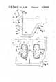
- FIG. 1is an isometric view of a shelf assembly constructed in accordance with the preferred embodiment of the invention
- FIG. 2is an elevational view of an apparatus for interlocking shelf members constructed in accordance with the preferred embodiment, shown in an initial, noninterlocked position;
- FIG. 3is an elevational view of the interlocking apparatus, shown in an interlocked position
- FIG. 4is an elevational view of a pair of connectors forming part of the interlocking apparatus
- FIG. 5is a sectional view, as seen from the plane indicated by the line 5--5 in FIG. 4;
- FIG. 6is a sectional view of the connectors as seen from the plane indicated by the lines 6--6 in FIG. 4;
- FIG. 7is an enlarged, fragmentary view of a vertical shelf member, illustrating apertures constructed in accordance with the preferred embodiment
- FIGS. 8a, 8bare both side elevational views of a corner upright, forming part of the shelf assembly
- FIG. 9is an end view of the upright shown in FIG. 8;
- FIG. 10is an elevational view of a "T" upright constructed in accordance with the preferred embodiment
- FIG. 11is an end view of the "T" upright shown in FIG. 10;
- FIG. 12is a side elevational view of the "T" upright
- FIG. 13is an isometric view of a shelf assembly embodying other features of the present invention.
- FIG. 14is an isometric view of a supplemental support member constructed in accordance with the preferred embodiment of the invention.
- FIG. 15is an end view of the supplemental support member
- FIG. 16is a fragmentary, isometric view of a transverse beam member
- FIG. 17is a side elevational view of a tie bar, constructed in accordance with the preferred embodiment.
- FIG. 18is an end view of the tie bar
- FIG. 19is a top view illustrating a co-interlocking between transverse beam members, the "T" upright and the tie bar;
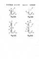
- FIGS. 20a-dare sectional views of transverse beam members having different strengths.
- FIG. 1illustrates the overall view of a shelf assembly 10 embodying the present invention.
- the shelf assemblycomprises four corner uprights 12, and a plurality of transverse beam members, indicated generally by the reference character 14, that extend between and interlock with adjacent corner uprights.
- the longer transverse beam members extending across the front and back of the shelf unit 10are designated by the reference character 14a, whereas the shorter transverse members extending front to back are designated by the reference character 14b.
- the interlocking members between the uprights 12 and the transverse members 14a, 14bare substantially identical.
- each transverse beamis of uniform cross-section longitudinally and includes a substantially flat side panel 30 and an integrally formed, rigidizing flange 32.
- the flange 32includes a lateral extension 32a that joins the side panel 30, a support lip 32b that extends substantially parallel with the lateral extension 32a and an angled portion 32c that joins the support lip 32b to the extension 32a.
- the lip 32bdefines a support for a shelf 34 (indicated in phantom in FIG. 5) or other component.
- transverse members 14(2 pairs of members 14a, 14b) mounted at the same level on the uprights 12 define a shelf support.
- the shelfis sized to fit within the perimeter defined by the transverse members and thus movement in the shelf is restricted by inside surfaces 30a of the side panels 30.
- the connectors 20are preferably formed near the ends of each transverse beam.
- the connectors 20each comprise a lug 40 spaced from an outside face 30b of the side panel 30 by a keyed pedestal 42.
- the pedestal 42is formed by an elongate projection defined by spaced, upper and lower lug supporting legs 44, 46, joined on one side by a curved interconnecting wall 48.
- the lug 40extends laterally from the pedestal in a direction substantially parallel with the plane of the outer face 30b of the side panel 30. With this arrangement, a track 49 is defined between the surface 30b and an undersurface 40a of the lug 40 for receiving a portion of the upright 12.
- the lugs 40 and keyed pedestals 42are preferably struck from the face panel 30 of the transverse beam 14, on one or more metal forming steps.
- the connectors 20are integrally formed with the beam members and the entire construction of the beam can thus be accomplished on high speed automatic metal forming equipment such as roll formers.
- the apertures 22are constructed to easily receive and interlock with a pair of connectors 20 formed at the ends of a transverse beam.
- Each aperture 22comprises an elongate slot having upper and lower slot segments 50a, 50b.
- a lug clearing notch 52extends laterally from one side to each upper slot portion 50a.
- the transverse dimension of the lower slot segment 50bgradually narrows from top to bottom so that an interference fit is created when the connectors 20 are engaged.
- the connectors 20 formed at the end of the transverse beam 14are interlocked with a pair of apertures 22 formed in an upright 12 by first positioning the upright 12 and the beam 14 as shown in FIG. 2 so that the connectors 20 pass through the upper slot segments 50a of the apertures 22.
- the transverse beam 14is then moved downwardly (as viewed in FIG. 2) so that the connectors 20 move into the position shown in FIG. 3.
- a portion of the uprightindicated by the reference character 60 in FIG. 2, is captured between the undersurface of the lug 40 and the outside face 30b of the transverse beam. This lug/upright engagement, prevents the beam and upright from lateral separation.
- the lug pedestals 42are keyed to provide an interference fit with the lower slot segments 50b when the connectors 20 are bottomed (as shown in FIG. 3).
- the interference engagement between the pedestals and lower slot segmentsinhibits relative rotational movement between the uprights 12 and the transverse beam 14, thus providing an extremely rigid interlocking of the shelf members, eliminating the need for supplementary cross-bracing.
- the connectors 20when the connectors 20 are fully seated in the lower slot segments 50b, at least three areas of contact between the pedestal 42 and the lower slot segment 50b occur.
- these areas of engagementare indicated by the reference characters 62a, 62b and 62c.
- the contact areas 62a, 62bare preferably effected between the lug-side of the lug support legs 44, 46 and one edge of the lower slot segment 50b.
- the contact 62cis effected between the interconnecting wall 48 and the opposite edge of the lower slot segment 50b.
- this arrangementprovides three spaced areas of contact with the areas 62a, 62b, and the area 62c disposed in either side of an imaginary vertical centerline 64 drawn through the connector.
- the engagement between the keyed pedestal 42 and the aperture 22resists relative rotation between an upright and a transverse beam, thus creating a rather rigid interlocking.
- the contact areas 62a and 62cdefine lines of contact between the edges of the lower slot segment 50b and the support leg 46 and the interconnecting wall 48, respectively. Consequently, a wedging engagement between the keyed pedestal 42 and the edges of the lower slot segment 50b is achieved when the connectors 20 are in the interlocked position shown in FIG. 3.
- each lug 40includes a reinforcing rib 66 to add additional rigidity to the lug.
- the ribimparts a slight radius to the lug 40, as seen in FIG. 5.
- the radiusnot only strengthens the lug 40 but the curved undersurface 40a facilitates the engagement between a transverse member 14 and the upright 12.
- the curved undersurface 40aprovides a "lead" so that when the connectors are moved from the position shown in FIG. 2 to the position in FIG. 3, the rounded edge defined by the lower surface 40a of the lug 40 easily overlaps the outer face 30b of the upright to facilitate the movement of the beam 14 into its final interlocked position.
- the transverse beammay be formed with holes 70 located a spaced distance above the connectors 20 as seen in FIG. 2.
- holes 70are aligned with respective upper slot segments 50a.
- a bolt or safety clip(not shown) can be inserted through the aligned opening to provide a rather permanent connection of the upright 12 and beam 14, if desired.
- FIGS. 8a, 8b and 9illustrate the construction of the corner uprights 12.
- each corner upright 12comprises two adjacent flat sections 12a, 12b oriented at an angle of substantially 90° with respect to each other to define an L-shaped configuration.
- a plurality of pairs of the apertures 22are spaced longitudinally along the entire length of each flat section 12a, 12b, enabling a plurality of transverse members 14a, 14b to be engaged at various locations to define plural shelf locations.
- FIGS. 10-12illustrate the construction of a "T" upright 80 for joining adjacent shelf units which also embodies the present invention.
- FIG. 13illustrates two interconnected shelf units utilizing the "T" uprights 80.
- the "T" uprightcomprises two spaced, co-planar, flat sections 80a joined together by U-shaped extension 80b that comprises a pair of substantially parallel flat wall extensions 82, 84 interconnected by an arcuate wall 86.
- the wall extensions 82, 84join the flat sections 80a at an angle of substantially 90°.
- Aligned pairs of apertures 22are disposed longitudinally along the flat sections 80a and the wall extensions 82, 84.
- At least two of the corner uprights 12are replaced with "T" uprights 80 as shown in FIG. 13.
- the front and back transverse members 14a of the adjacent shelf unitsinterlock with the flat sections 80a whereas the front-to-back transverse beams 14b interlock with at least one of the wall extensions 82, 84.
- a single front-to-back transverse beam 14b extending between the U-shaped extensions 80b of the "T" uprights 80will be sufficient at each shelf location.
- transverse beams 14bcan be interlocked with both wall extensions 82, 84 as shown in FIG. 13.
- FIG. 13illustrates other important features of the invention. Due to the symmetrical configuration of the connectors, the transverse beams 14 are invertible and can be interlocked to the uprights 12, 80 with the rigidizing flange 32 at the top or bottom of the side panel 30. In FIG. 13, the transverse beams 14a, 14b are positioned with their flanges 32 on top, that is, inverted from the position shown in FIGS. 2-5. The shelves 34 sit atop the flange extensions 32a (shown in the inverted position in FIG. 5) of the flanges 32 and are retained in position by the uprights.
- the shelving assembly shown in FIG. 13includes supplemental support members 88 that extend front-to-back, that is, parallel to the transverse beams 14b.
- the supports 88engage and are supported by the transverse beams 14a.
- the supplemental supports 88provide additional support for the shelves 34 and in addition can serve as dividers, as well as component and hanger supports for shelf applications such as racks for storing and supporting automobile/truck exhaust pipe inventories.
- the supplemental supports 88comprise elongate members having a channel-like construction.
- Each member 88includes a flat planar section 88a which abuttably engages the underside of a shelf 34 when the member 88 is used as a shelf support.
- a pair of rigidizing flanges 88bdepend downwardly from either side of the flat section 88a.
- Each flange 88bincludes leg portions 90, 91 joined by a short transverse web 92. The size of the legs 91, 92 can be varied to suit particular strength requirements.
- the flat section 88a and flanges 88binclude apertures 93 for receiving fasteners, hangers, etc.
- a tab 94depends downwardly at each end of the supplemental member 88 and preferably includes a small aperture 94a.
- the tabs 94are engaged with slots 96 in opposite transverse members 14a formed at spaced locations in the flange 32 near the juncture of the flange extension 32a and the connecting web 32c. It should thus be appreciated that the supplemental members 88 are easily installed in a shelf unit, by merely inserting the tabs 94 into the slots 96 in opposite transverse beams. To maintain the engagement, the tabs 94 can be bent or alternately, fasteners such as screws or clips (not shown) can be placed in the tab apertures 94a.
- the disclosed "T" upright 80provides yet another feature of the present invention.
- the spaced apart shelf unitscan only be joined with the use of special brackets or other components that are fastened to the respective shelf units by separate fasteners.
- spaced apart shelf unitsare connected using a tie bar 96 illustrated in FIG. 17 which includes connectors 20, substantially identical to those forming part of the transverse beams, which interlock with the apertures 22 in the "T" section.
- the tie bar 96(which is shown standing on end in FIG. 17) includes a flat planar section 96a and a pair of 90° flanges 90b which serve to reinforce the tie bar.
- tie bars 96can serve not only as a means for "tying together" space shelf units but can serve as a support for a raised aisleway in multiple story shelf assemblies.
- the corner and "T" uprights 12, 80can be manufactured in lengths of 10 feet or longer to provide shelf units more than 15 feet tall (2 stories).
- tie bars 96can be used to interconnect two spaced shelf units which in turn serve as a support for grating or flooring to define an aisleway space above ground level between the adjacent shelf units.
- each flat section 80ais interlocked with a transverse beam 14a.
- At least one leg of the U sectionis interlocked with a front-to-back transverse beam 14b.
- a tie bar 96is inserted inside the U-shaped extension and interlocked with one of the extension walls 82, 84 forming the U-shaped extension.
- the transverse beams 14a, 14bwould be interlocked with apertures 22 all located at the same level of the "T" upright 80.
- the tie bar 96would preferably be interlocked with a set of apertures spaced above or below the apertures engaged by the transverse members.
- the transverse member 14illustrated in the Figures, includes a pair of symmetrical connectors 20 at each end which as indicated previously enables the beam 14 to be installed with the flange 32 either at the top or the bottom. If a stronger transverse member is desired, the side panel 30, or for that matter the flange 32 can be increased in size to provide the additional strength needed. In the preferred embodiment, additional strength in the transverse beam 14 is obtained by increasing the width of the side panel 30.
- two pairs of connectors 20can be incorporated to provide a stronger interlocking engagement between an upright and a transverse member.
- Modificationscan also be made to reduce material cost for shelves intended for very light applications.
- the "T" upright 80 illustrated in FIGS. 10-12is illustrated with an extension 80b comprising two wall extensions 82, 84, each formed with a plurality of pairs of apertures 22.
- single apertures 22 spaced longitudinally along each wall extension 82, 84can be utilized which engage transverse members having only a single connector 20, or alternately a vertically spaced pair of connectors 20 (not shown).
- the flanges shown for the various memberscan be reduced in size or even eliminated for light duty applications.
- Each of the shelf elementsis configured to facilitate manufacture on high speed metal forming equipment such as rolling equipment. Consequently, the various members can be manufactured continuously and cut into any length desired so that relatively large shelf units can be assembled.
- the same tooling, with minimum modification or adjustmentcan roll the shelf members for both light and heavy duty shelf units.
- the same rolling equipmentcould form transverse members 14 having various side panel widths. In effect, the strength of a transverse member would be determined by the initial width of the sheet stock fed to the rolling equipment. The wider the initial stock, the wider the side panel 30 and hence the stronger the finished transverse member.
- FIGS. 20a-dillustrates a range of transverse beams 14 denoted for purposes of explanation as 14', 14", 14'" and 14"".
- additional strengthis obtained by increasing the width of the side panel 30 and the addition of another rigidizing flange 98 (not shown in FIG. 20d as part of beam 14"").
- the flange 32remains unchanged, so that all four illustrated beams can be formed on the same rolling equipment with minimal change.
- the width of the initial stockdictates the strength of the resulting beam.
- additional connectors 20are formed at the beam ends in the higher strength beams 14'", 14"".
- the connectors 20are formed symmetrically so that the beams 14 shown in these two Figures can also be installed in the inverted position.
- shelf unitscan be quickly assembled without the need for separate fasteners.
- the interlockingprovides an extremely rigid structure without the need for separate cross bracing, but yet is easily disassembled if shelf repositioning, removal, etc. is needed.
- the location of the shelves (or transverse member 14)is fully adjustable by virtue of the plurality of apertures 22 formed along the length of the uprights.
Landscapes
- Assembled Shelves (AREA)
Abstract
Description
Claims (38)
Priority Applications (2)
| Application Number | Priority Date | Filing Date | Title |
|---|---|---|---|
| US06/414,554US4549665A (en) | 1982-09-03 | 1982-09-03 | Shelf assembly |
| EP83305105AEP0102841A1 (en) | 1982-09-03 | 1983-09-02 | Shelf assembly |
Applications Claiming Priority (1)
| Application Number | Priority Date | Filing Date | Title |
|---|---|---|---|
| US06/414,554US4549665A (en) | 1982-09-03 | 1982-09-03 | Shelf assembly |
Publications (1)
| Publication Number | Publication Date |
|---|---|
| US4549665Atrue US4549665A (en) | 1985-10-29 |
Family
ID=23641953
Family Applications (1)
| Application Number | Title | Priority Date | Filing Date |
|---|---|---|---|
| US06/414,554Expired - Fee RelatedUS4549665A (en) | 1982-09-03 | 1982-09-03 | Shelf assembly |
Country Status (2)
| Country | Link |
|---|---|
| US (1) | US4549665A (en) |
| EP (1) | EP0102841A1 (en) |
Cited By (36)
| Publication number | Priority date | Publication date | Assignee | Title |
|---|---|---|---|---|
| US4646656A (en)* | 1985-09-26 | 1987-03-03 | Marschak Howard J | Base shelf locking mechanism |
| US4996929A (en)* | 1989-10-10 | 1991-03-05 | Saal Bruno P | Shelf frame connector |
| US5485932A (en)* | 1994-05-03 | 1996-01-23 | Digital Equipment Corporation | Wall mountable modular component mounting system |
| US5489162A (en)* | 1993-02-10 | 1996-02-06 | Digital Equipment Corporation | Fastening |
| US5495954A (en)* | 1994-05-16 | 1996-03-05 | Schmit; Joel A. | Modular storage unit kit |
| FR2747284A1 (en)* | 1996-04-12 | 1997-10-17 | Osf Inc | Shelving with vertical U-shaped sections holding shelves |
| EP0701788A3 (en)* | 1994-09-14 | 1998-01-07 | Esmena, S.A. | Girder for the construction of shelves |
| USD430431S (en)* | 1999-02-17 | 2000-09-05 | Fehlbaum & Co. | Display unit |
| US6450350B1 (en)* | 2000-06-12 | 2002-09-17 | John V. R. Krummell, Jr. | Storage rack system with flared end load beam |
| US20030094124A1 (en)* | 2001-11-20 | 2003-05-22 | Wishart Andrew S. | Modular pallet display system |
| GB2388015A (en)* | 2002-05-01 | 2003-11-05 | Jennifer Frances Massicott | Shelf support bracket |
| US7070021B1 (en) | 2003-01-10 | 2006-07-04 | Mckinney Steven L | Rack step tool |
| US20060196842A1 (en)* | 2005-03-04 | 2006-09-07 | Taylor Harry R | Storage rack |
| US20070246434A1 (en)* | 2006-02-03 | 2007-10-25 | Honda Motor Co., Ltd. | Muffler Pipe Rack and Hanger System |
| US20080193334A1 (en)* | 2007-02-08 | 2008-08-14 | Dale Ryan | Two dimensional sample handler |
| RU2347516C1 (en)* | 2007-10-30 | 2009-02-27 | ОАО "Опытный завод УНИПТИМАШ" | Connection of elements of collapsible racks, sales and warehouse equipment and building structures |
| US20090090686A1 (en)* | 2004-12-30 | 2009-04-09 | Edsal Manufacturing Co., Inc. | Shelving connector |
| US20100089699A1 (en)* | 2008-10-15 | 2010-04-15 | Meltz George R | System and apparatus for supportive scaffolding |
| US20120000871A1 (en)* | 2010-07-02 | 2012-01-05 | Edsal Manufacturing Co., Inc. | Portion of shelf and support for shelving unit |
| US20120012549A1 (en)* | 2010-07-16 | 2012-01-19 | Hon Hai Precision Industry Co., Ltd. | Rack frame |
| USD653101S1 (en) | 2011-06-01 | 2012-01-31 | Cheon Soon Choi | Single structural member for shelving |
| USD653528S1 (en) | 2011-06-01 | 2012-02-07 | Cheon Soon Choi | Horizontal structural member for shelving |
| USD653527S1 (en) | 2011-06-01 | 2012-02-07 | Cheon Soon Choi | Vertical structural member for shelving |
| US20120274190A1 (en)* | 2011-04-27 | 2012-11-01 | Hon Hai Precision Industry Co., Ltd. | Electronic device enclosure |
| US20140217252A1 (en)* | 2010-07-02 | 2014-08-07 | Edsal Manufacturing Co., Inc. | Variable configuration shelving apparatus and methods |
| US9204737B2 (en) | 2013-04-08 | 2015-12-08 | Presentoirs One Way Inc. | Modular shelving system |
| RU2639618C1 (en)* | 2016-07-26 | 2017-12-21 | Общество с ограниченной ответственностью "Эргономика Пространства" (ООО "Эргономика Пространства") | Attachment assembly of rack structure elements |
| US20180279782A1 (en)* | 2017-03-28 | 2018-10-04 | Edsal Manufacturing Company, Inc. | Shelving unit with capacity increasing tie members |
| US10165855B2 (en)* | 2010-05-26 | 2019-01-01 | Seville Classics, Inc. | Storage rack |
| US20190167001A1 (en)* | 2017-12-04 | 2019-06-06 | Grass Gmbh | Guide rail of a guidance system, guidance system, method for producing a guide rail and furniture |
| EP3606380A4 (en)* | 2017-04-03 | 2021-02-24 | Globerman, Eyal | Method for making shelves |
| USD942784S1 (en)* | 2019-10-08 | 2022-02-08 | Brian Burge | Table |
| US20220056713A1 (en)* | 2020-08-18 | 2022-02-24 | Three G Metal Fabrications Ltd | Modular Platform System Components and Tools |
| WO2022060888A1 (en)* | 2020-09-16 | 2022-03-24 | Perfect Site LLC | Utility rack |
| US11896121B2 (en) | 2017-04-03 | 2024-02-13 | Eyal GLOBERMAN | Method for making shelves |
| USD1050784S1 (en)* | 2022-05-16 | 2024-11-12 | Edsal Manufacturing Company, Llc | Shelving unit post with keyhole |
Families Citing this family (2)
| Publication number | Priority date | Publication date | Assignee | Title |
|---|---|---|---|---|
| ATE192028T1 (en)* | 1995-07-05 | 2000-05-15 | Anemos S P A | CONNECTING DEVICE FOR LIGHTWEIGHT METAL SHELVES |
| ITMI20040280U1 (en)* | 2004-06-11 | 2004-09-11 | Whirlpool Co | MULTI-PURPOSE SUPPORT FOR SHELVES OF REFRIGERATING OR SIMILAR APPLIANCES, PARTICULARLY SUITABLE FOR MODULAR APPLIANCES |
Citations (67)
| Publication number | Priority date | Publication date | Assignee | Title |
|---|---|---|---|---|
| NL285256A (en)* | ||||
| US1254094A (en)* | 1916-10-16 | 1918-01-22 | Engelbert J Vogt | Adjustable bracket. |
| US1288010A (en)* | 1918-07-06 | 1918-12-17 | William Harry Isaac | Shelf-bracket. |
| US2895619A (en)* | 1958-06-27 | 1959-07-21 | Midland Machine Corp | Storage rack |
| US2918176A (en)* | 1957-02-25 | 1959-12-22 | Allen Iron & Steel Company | Storage rack |
| US2932409A (en)* | 1954-12-09 | 1960-04-12 | Jr Walter G Wineman | Metal shelving |
| US2932368A (en)* | 1956-06-15 | 1960-04-12 | Storage Products Corp | Structural lock |
| US2948409A (en)* | 1958-07-11 | 1960-08-09 | Equipment Mfg Inc | Rack construction |
| US2984363A (en)* | 1958-07-24 | 1961-05-16 | Mechanical Handling Sys Inc | Adjustable rack |
| US2990920A (en)* | 1958-01-21 | 1961-07-04 | Republic Steel Corp | Structural building elements |
| US3043409A (en)* | 1959-05-25 | 1962-07-10 | Rapids Standard Co Inc | Perforated structural angle |
| US3045834A (en)* | 1957-07-25 | 1962-07-24 | Edward A Seiz | Rack construction |
| US3055462A (en)* | 1960-10-21 | 1962-09-25 | Bathey Mfg Company | Self-locking connection for structural members |
| US3070237A (en)* | 1960-06-30 | 1962-12-25 | Acme Steel Co | Pallet rack |
| US3095975A (en)* | 1961-05-15 | 1963-07-02 | Allen Iron & Steel Company | Storage rack |
| US3096108A (en)* | 1961-03-16 | 1963-07-02 | Green Penny Co | Adjustable rack connection |
| US3097747A (en)* | 1959-05-19 | 1963-07-16 | Bernard Gloekler North East Co | Pallet rack |
| US3106297A (en)* | 1960-11-21 | 1963-10-08 | Acme Steel Co | Pallet rack |
| CH379078A (en)* | 1960-03-03 | 1964-06-30 | Nember Fausto | Shelving with modular elements |
| US3144944A (en)* | 1962-03-19 | 1964-08-18 | Acme Steel Co | Drive-in pallet rack |
| US3144945A (en)* | 1962-03-06 | 1964-08-18 | Edward A Seiz | Storage rack |
| US3152620A (en)* | 1962-09-26 | 1964-10-13 | John D Riordan | Woven narrow web with ornamental selvage |
| US3186527A (en)* | 1963-03-07 | 1965-06-01 | Speedrack Inc | Structural lock |
| US3195735A (en)* | 1962-03-02 | 1965-07-20 | Jarke Mfg Company | Detachable structure and joint therefor |
| US3208778A (en)* | 1962-10-04 | 1965-09-28 | Storack Corp | Interlocking structural members |
| FR1460886A (en)* | 1965-10-21 | 1966-01-07 | Corner bar for shelving units with smooth wing and perforated wing | |
| US3240352A (en)* | 1963-05-31 | 1966-03-15 | Palmer Shile Co | Safety lock for adjustable storage racks |
| US3266635A (en)* | 1964-09-09 | 1966-08-16 | Interlake Steel Corp | Control rib for different thickness material of uprights |
| US3273720A (en)* | 1966-09-20 | Storage racks | ||
| US3291319A (en)* | 1965-03-04 | 1966-12-13 | William H Novales | Self-locking shelving frame members |
| US3303937A (en)* | 1964-09-09 | 1967-02-14 | Interlake Steel Corp | Pallet rack |
| US3330229A (en)* | 1965-10-21 | 1967-07-11 | Hirsh Mfg Co Sa | Knockdown steel shelving unit and corner fastening means therefor |
| US3337062A (en)* | 1965-10-23 | 1967-08-22 | Edward A Seiz | Storage racks |
| US3346126A (en)* | 1965-06-28 | 1967-10-10 | Bloom Milton | Adjustable rack shelving |
| US3351212A (en)* | 1966-01-07 | 1967-11-07 | Interlake Steel Corp | Pallet rack construction |
| US3352584A (en)* | 1964-12-16 | 1967-11-14 | Redirack Ind Ltd | Locking pin device for pallet rack |
| US3362738A (en)* | 1965-07-27 | 1968-01-09 | Unistrut Corp | Adjustable fittings |
| US3391795A (en)* | 1966-06-23 | 1968-07-09 | Interlake Steel Corp | Drive-in pallet rack |
| US3392848A (en)* | 1966-06-06 | 1968-07-16 | Interlake Steel Corp | Pallet rack |
| US3414224A (en)* | 1966-03-28 | 1968-12-03 | Dexion Ltd | Interlock structural members |
| US3422962A (en)* | 1966-06-29 | 1969-01-21 | Interlake Steel Corp | Pallet rack |
| US3438343A (en)* | 1967-03-30 | 1969-04-15 | Interlake Steel Corp | Stacking frames for pallets |
| US3456970A (en)* | 1966-09-06 | 1969-07-22 | Dexion Ltd | Connections between structural components |
| US3463325A (en)* | 1967-06-22 | 1969-08-26 | Interlake Steel Corp | Pallet rack beam retainer |
| US3472539A (en)* | 1969-01-02 | 1969-10-14 | Streater Ind Inc | Tubular frame joint member |
| DE1803107A1 (en)* | 1968-03-07 | 1969-10-16 | Giacomo Valsesia | Metal shelf |
| US3499672A (en)* | 1966-08-08 | 1970-03-10 | Dexion Ltd | Connections between structural components |
| US3510010A (en)* | 1968-05-16 | 1970-05-05 | Leon J Gasner | Pallet racks |
| US3512653A (en)* | 1968-02-09 | 1970-05-19 | Paul Erismann | Support for loading pallets and the like |
| US3545626A (en)* | 1968-05-10 | 1970-12-08 | Edward Seiz | Storage structure |
| US3565264A (en)* | 1968-04-16 | 1971-02-23 | Republic Steel Corp | Pallet rack equipped with sheet metal structural member |
| US3612290A (en)* | 1969-08-12 | 1971-10-12 | Aurora Equipment Co | Releasable key clamp for a pallet rack |
| US3626487A (en)* | 1970-03-03 | 1971-12-07 | Edward A Seiz | Fire and vermin resistant storage structure having fail-safe features |
| US3631821A (en)* | 1969-09-11 | 1972-01-04 | Basil Zachariou | Shelving assemblies |
| US3647080A (en)* | 1970-06-12 | 1972-03-07 | Inca Metal Products Corp | Structural element and structure |
| US3648426A (en)* | 1969-08-04 | 1972-03-14 | Banwari Lal Chaudhary | Constructional elements |
| US3702137A (en)* | 1970-06-04 | 1972-11-07 | Aurora Equipment Co | Latching mechanism |
| US3726414A (en)* | 1971-06-28 | 1973-04-10 | Speedrack Inc | Storage rack and beam for use therein |
| US3741405A (en)* | 1971-07-20 | 1973-06-26 | Interlake Inc | Load lock |
| US3846944A (en)* | 1970-12-21 | 1974-11-12 | Barton King Syst Corp | Structural self-supporting system |
| US3862691A (en)* | 1973-06-01 | 1975-01-28 | Lear Siegler Inc | Lock span shelving |
| US3905212A (en)* | 1974-10-18 | 1975-09-16 | Alba Waldensian | Inspection toe for anti-embolism stocking |
| US3986318A (en)* | 1974-09-30 | 1976-10-19 | Interlake, Inc. | Structural member and assembly thereof |
| US4078664A (en)* | 1977-03-25 | 1978-03-14 | Interlake, Inc. | Cross bar |
| US4106630A (en)* | 1977-04-28 | 1978-08-15 | Parsteel Products Company, Inc. | Storage rack assembly |
| DE3002401A1 (en)* | 1979-01-26 | 1980-08-07 | Gabriele Pozzer | COMPOSIBLE SHELF IN THE MODULAR SYSTEM |
| FR2447164A1 (en)* | 1979-01-26 | 1980-08-22 | Guillemin Henri | Demountable modular shelving frame - includes U=section post with interactive folded flaps which guide angle shoe into place |
- 1982
- 1982-09-03USUS06/414,554patent/US4549665A/ennot_activeExpired - Fee Related
- 1983
- 1983-09-02EPEP83305105Apatent/EP0102841A1/ennot_activeWithdrawn
Patent Citations (67)
| Publication number | Priority date | Publication date | Assignee | Title |
|---|---|---|---|---|
| US3273720A (en)* | 1966-09-20 | Storage racks | ||
| NL285256A (en)* | ||||
| US1254094A (en)* | 1916-10-16 | 1918-01-22 | Engelbert J Vogt | Adjustable bracket. |
| US1288010A (en)* | 1918-07-06 | 1918-12-17 | William Harry Isaac | Shelf-bracket. |
| US2932409A (en)* | 1954-12-09 | 1960-04-12 | Jr Walter G Wineman | Metal shelving |
| US2932368A (en)* | 1956-06-15 | 1960-04-12 | Storage Products Corp | Structural lock |
| US2918176A (en)* | 1957-02-25 | 1959-12-22 | Allen Iron & Steel Company | Storage rack |
| US3045834A (en)* | 1957-07-25 | 1962-07-24 | Edward A Seiz | Rack construction |
| US2990920A (en)* | 1958-01-21 | 1961-07-04 | Republic Steel Corp | Structural building elements |
| US2895619A (en)* | 1958-06-27 | 1959-07-21 | Midland Machine Corp | Storage rack |
| US2948409A (en)* | 1958-07-11 | 1960-08-09 | Equipment Mfg Inc | Rack construction |
| US2984363A (en)* | 1958-07-24 | 1961-05-16 | Mechanical Handling Sys Inc | Adjustable rack |
| US3097747A (en)* | 1959-05-19 | 1963-07-16 | Bernard Gloekler North East Co | Pallet rack |
| US3043409A (en)* | 1959-05-25 | 1962-07-10 | Rapids Standard Co Inc | Perforated structural angle |
| CH379078A (en)* | 1960-03-03 | 1964-06-30 | Nember Fausto | Shelving with modular elements |
| US3070237A (en)* | 1960-06-30 | 1962-12-25 | Acme Steel Co | Pallet rack |
| US3055462A (en)* | 1960-10-21 | 1962-09-25 | Bathey Mfg Company | Self-locking connection for structural members |
| US3106297A (en)* | 1960-11-21 | 1963-10-08 | Acme Steel Co | Pallet rack |
| US3096108A (en)* | 1961-03-16 | 1963-07-02 | Green Penny Co | Adjustable rack connection |
| US3095975A (en)* | 1961-05-15 | 1963-07-02 | Allen Iron & Steel Company | Storage rack |
| US3195735A (en)* | 1962-03-02 | 1965-07-20 | Jarke Mfg Company | Detachable structure and joint therefor |
| US3144945A (en)* | 1962-03-06 | 1964-08-18 | Edward A Seiz | Storage rack |
| US3144944A (en)* | 1962-03-19 | 1964-08-18 | Acme Steel Co | Drive-in pallet rack |
| US3152620A (en)* | 1962-09-26 | 1964-10-13 | John D Riordan | Woven narrow web with ornamental selvage |
| US3208778A (en)* | 1962-10-04 | 1965-09-28 | Storack Corp | Interlocking structural members |
| US3186527A (en)* | 1963-03-07 | 1965-06-01 | Speedrack Inc | Structural lock |
| US3240352A (en)* | 1963-05-31 | 1966-03-15 | Palmer Shile Co | Safety lock for adjustable storage racks |
| US3303937A (en)* | 1964-09-09 | 1967-02-14 | Interlake Steel Corp | Pallet rack |
| US3266635A (en)* | 1964-09-09 | 1966-08-16 | Interlake Steel Corp | Control rib for different thickness material of uprights |
| US3352584A (en)* | 1964-12-16 | 1967-11-14 | Redirack Ind Ltd | Locking pin device for pallet rack |
| US3291319A (en)* | 1965-03-04 | 1966-12-13 | William H Novales | Self-locking shelving frame members |
| US3346126A (en)* | 1965-06-28 | 1967-10-10 | Bloom Milton | Adjustable rack shelving |
| US3362738A (en)* | 1965-07-27 | 1968-01-09 | Unistrut Corp | Adjustable fittings |
| US3330229A (en)* | 1965-10-21 | 1967-07-11 | Hirsh Mfg Co Sa | Knockdown steel shelving unit and corner fastening means therefor |
| FR1460886A (en)* | 1965-10-21 | 1966-01-07 | Corner bar for shelving units with smooth wing and perforated wing | |
| US3337062A (en)* | 1965-10-23 | 1967-08-22 | Edward A Seiz | Storage racks |
| US3351212A (en)* | 1966-01-07 | 1967-11-07 | Interlake Steel Corp | Pallet rack construction |
| US3414224A (en)* | 1966-03-28 | 1968-12-03 | Dexion Ltd | Interlock structural members |
| US3392848A (en)* | 1966-06-06 | 1968-07-16 | Interlake Steel Corp | Pallet rack |
| US3391795A (en)* | 1966-06-23 | 1968-07-09 | Interlake Steel Corp | Drive-in pallet rack |
| US3422962A (en)* | 1966-06-29 | 1969-01-21 | Interlake Steel Corp | Pallet rack |
| US3499672A (en)* | 1966-08-08 | 1970-03-10 | Dexion Ltd | Connections between structural components |
| US3456970A (en)* | 1966-09-06 | 1969-07-22 | Dexion Ltd | Connections between structural components |
| US3438343A (en)* | 1967-03-30 | 1969-04-15 | Interlake Steel Corp | Stacking frames for pallets |
| US3463325A (en)* | 1967-06-22 | 1969-08-26 | Interlake Steel Corp | Pallet rack beam retainer |
| US3512653A (en)* | 1968-02-09 | 1970-05-19 | Paul Erismann | Support for loading pallets and the like |
| DE1803107A1 (en)* | 1968-03-07 | 1969-10-16 | Giacomo Valsesia | Metal shelf |
| US3565264A (en)* | 1968-04-16 | 1971-02-23 | Republic Steel Corp | Pallet rack equipped with sheet metal structural member |
| US3545626A (en)* | 1968-05-10 | 1970-12-08 | Edward Seiz | Storage structure |
| US3510010A (en)* | 1968-05-16 | 1970-05-05 | Leon J Gasner | Pallet racks |
| US3472539A (en)* | 1969-01-02 | 1969-10-14 | Streater Ind Inc | Tubular frame joint member |
| US3648426A (en)* | 1969-08-04 | 1972-03-14 | Banwari Lal Chaudhary | Constructional elements |
| US3612290A (en)* | 1969-08-12 | 1971-10-12 | Aurora Equipment Co | Releasable key clamp for a pallet rack |
| US3631821A (en)* | 1969-09-11 | 1972-01-04 | Basil Zachariou | Shelving assemblies |
| US3626487A (en)* | 1970-03-03 | 1971-12-07 | Edward A Seiz | Fire and vermin resistant storage structure having fail-safe features |
| US3702137A (en)* | 1970-06-04 | 1972-11-07 | Aurora Equipment Co | Latching mechanism |
| US3647080A (en)* | 1970-06-12 | 1972-03-07 | Inca Metal Products Corp | Structural element and structure |
| US3846944A (en)* | 1970-12-21 | 1974-11-12 | Barton King Syst Corp | Structural self-supporting system |
| US3726414A (en)* | 1971-06-28 | 1973-04-10 | Speedrack Inc | Storage rack and beam for use therein |
| US3741405A (en)* | 1971-07-20 | 1973-06-26 | Interlake Inc | Load lock |
| US3862691A (en)* | 1973-06-01 | 1975-01-28 | Lear Siegler Inc | Lock span shelving |
| US3986318A (en)* | 1974-09-30 | 1976-10-19 | Interlake, Inc. | Structural member and assembly thereof |
| US3905212A (en)* | 1974-10-18 | 1975-09-16 | Alba Waldensian | Inspection toe for anti-embolism stocking |
| US4078664A (en)* | 1977-03-25 | 1978-03-14 | Interlake, Inc. | Cross bar |
| US4106630A (en)* | 1977-04-28 | 1978-08-15 | Parsteel Products Company, Inc. | Storage rack assembly |
| DE3002401A1 (en)* | 1979-01-26 | 1980-08-07 | Gabriele Pozzer | COMPOSIBLE SHELF IN THE MODULAR SYSTEM |
| FR2447164A1 (en)* | 1979-01-26 | 1980-08-22 | Guillemin Henri | Demountable modular shelving frame - includes U=section post with interactive folded flaps which guide angle shoe into place |
Cited By (59)
| Publication number | Priority date | Publication date | Assignee | Title |
|---|---|---|---|---|
| US4646656A (en)* | 1985-09-26 | 1987-03-03 | Marschak Howard J | Base shelf locking mechanism |
| US4996929A (en)* | 1989-10-10 | 1991-03-05 | Saal Bruno P | Shelf frame connector |
| US5489162A (en)* | 1993-02-10 | 1996-02-06 | Digital Equipment Corporation | Fastening |
| US5485932A (en)* | 1994-05-03 | 1996-01-23 | Digital Equipment Corporation | Wall mountable modular component mounting system |
| US5495954A (en)* | 1994-05-16 | 1996-03-05 | Schmit; Joel A. | Modular storage unit kit |
| US5588540A (en)* | 1994-05-16 | 1996-12-31 | Schmit; Joel A. | Modular storage unit kit |
| EP0701788A3 (en)* | 1994-09-14 | 1998-01-07 | Esmena, S.A. | Girder for the construction of shelves |
| ES2157695A1 (en)* | 1996-04-12 | 2001-08-16 | Osf Inc | Backroom shelving system |
| US5735221A (en)* | 1996-04-12 | 1998-04-07 | Benayon; Jaime | Backroom shelving system |
| FR2747284A1 (en)* | 1996-04-12 | 1997-10-17 | Osf Inc | Shelving with vertical U-shaped sections holding shelves |
| USD430431S (en)* | 1999-02-17 | 2000-09-05 | Fehlbaum & Co. | Display unit |
| US6450350B1 (en)* | 2000-06-12 | 2002-09-17 | John V. R. Krummell, Jr. | Storage rack system with flared end load beam |
| US20030094124A1 (en)* | 2001-11-20 | 2003-05-22 | Wishart Andrew S. | Modular pallet display system |
| GB2388015A (en)* | 2002-05-01 | 2003-11-05 | Jennifer Frances Massicott | Shelf support bracket |
| US7070021B1 (en) | 2003-01-10 | 2006-07-04 | Mckinney Steven L | Rack step tool |
| US20090090686A1 (en)* | 2004-12-30 | 2009-04-09 | Edsal Manufacturing Co., Inc. | Shelving connector |
| US20060196842A1 (en)* | 2005-03-04 | 2006-09-07 | Taylor Harry R | Storage rack |
| US20070246434A1 (en)* | 2006-02-03 | 2007-10-25 | Honda Motor Co., Ltd. | Muffler Pipe Rack and Hanger System |
| US7950533B2 (en) | 2006-02-03 | 2011-05-31 | Honda Motor Co., Ltd. | Muffler pipe rack and hanger system |
| US20080193334A1 (en)* | 2007-02-08 | 2008-08-14 | Dale Ryan | Two dimensional sample handler |
| US7867768B2 (en) | 2007-02-08 | 2011-01-11 | Ortho-Clinical Diagnostics, Inc. | Two dimensional sample handler |
| RU2347516C1 (en)* | 2007-10-30 | 2009-02-27 | ОАО "Опытный завод УНИПТИМАШ" | Connection of elements of collapsible racks, sales and warehouse equipment and building structures |
| US20100089699A1 (en)* | 2008-10-15 | 2010-04-15 | Meltz George R | System and apparatus for supportive scaffolding |
| US11564488B2 (en)* | 2010-05-26 | 2023-01-31 | Seville Classics Inc | Storage rack |
| US20230157446A1 (en)* | 2010-05-26 | 2023-05-25 | Seville Classics Inc. | Storage Rack |
| US20250228363A1 (en)* | 2010-05-26 | 2025-07-17 | Seville Classics, Inc. | Storage Rack |
| US12268299B2 (en)* | 2010-05-26 | 2025-04-08 | Seville Classics Inc. | Storage rack |
| US20240138564A1 (en)* | 2010-05-26 | 2024-05-02 | Seville Classics Inc. | Storage Rack |
| US20200085189A1 (en)* | 2010-05-26 | 2020-03-19 | Seville Classics Inc. | Storage Rack |
| US10485337B2 (en)* | 2010-05-26 | 2019-11-26 | Seville Classics, Inc. | Storage rack |
| US10806252B2 (en)* | 2010-05-26 | 2020-10-20 | Seville Classics Inc. | Storage rack |
| US11930923B2 (en)* | 2010-05-26 | 2024-03-19 | Seville Classics Inc. | Storage rack |
| US20220192371A1 (en)* | 2010-05-26 | 2022-06-23 | Seville Classics Inc. | Storage Rack |
| US10165855B2 (en)* | 2010-05-26 | 2019-01-01 | Seville Classics, Inc. | Storage rack |
| US20120000871A1 (en)* | 2010-07-02 | 2012-01-05 | Edsal Manufacturing Co., Inc. | Portion of shelf and support for shelving unit |
| US20140217252A1 (en)* | 2010-07-02 | 2014-08-07 | Edsal Manufacturing Co., Inc. | Variable configuration shelving apparatus and methods |
| US9101216B2 (en)* | 2010-07-02 | 2015-08-11 | Edsal Manufacturing Company, Inc. | Variable configuration shelving apparatus and method |
| US9375102B2 (en)* | 2010-07-02 | 2016-06-28 | Edsal Manufacturing Company, Inc. | Portion of shelf and support for shelving unit |
| US20120012549A1 (en)* | 2010-07-16 | 2012-01-19 | Hon Hai Precision Industry Co., Ltd. | Rack frame |
| US20120274190A1 (en)* | 2011-04-27 | 2012-11-01 | Hon Hai Precision Industry Co., Ltd. | Electronic device enclosure |
| USD653101S1 (en) | 2011-06-01 | 2012-01-31 | Cheon Soon Choi | Single structural member for shelving |
| USD653528S1 (en) | 2011-06-01 | 2012-02-07 | Cheon Soon Choi | Horizontal structural member for shelving |
| USD653527S1 (en) | 2011-06-01 | 2012-02-07 | Cheon Soon Choi | Vertical structural member for shelving |
| US9204737B2 (en) | 2013-04-08 | 2015-12-08 | Presentoirs One Way Inc. | Modular shelving system |
| RU2639618C1 (en)* | 2016-07-26 | 2017-12-21 | Общество с ограниченной ответственностью "Эргономика Пространства" (ООО "Эргономика Пространства") | Attachment assembly of rack structure elements |
| US10299594B2 (en)* | 2017-03-28 | 2019-05-28 | Edsal Manufacturing Company, Inc. | Shelving unit with capacity increasing tie members |
| US20180279782A1 (en)* | 2017-03-28 | 2018-10-04 | Edsal Manufacturing Company, Inc. | Shelving unit with capacity increasing tie members |
| US11896121B2 (en) | 2017-04-03 | 2024-02-13 | Eyal GLOBERMAN | Method for making shelves |
| US11219308B2 (en)* | 2017-04-03 | 2022-01-11 | Eyal GLOBERMAN | Method for making shelves |
| EP3606380A4 (en)* | 2017-04-03 | 2021-02-24 | Globerman, Eyal | Method for making shelves |
| US10750862B2 (en)* | 2017-12-04 | 2020-08-25 | Grass Gmbh | Guide rail of a guidance system, guidance system, method for producing a guide rail and furniture |
| US20190167001A1 (en)* | 2017-12-04 | 2019-06-06 | Grass Gmbh | Guide rail of a guidance system, guidance system, method for producing a guide rail and furniture |
| USD942784S1 (en)* | 2019-10-08 | 2022-02-08 | Brian Burge | Table |
| US20220056713A1 (en)* | 2020-08-18 | 2022-02-24 | Three G Metal Fabrications Ltd | Modular Platform System Components and Tools |
| WO2022060888A1 (en)* | 2020-09-16 | 2022-03-24 | Perfect Site LLC | Utility rack |
| US11647833B2 (en) | 2020-09-16 | 2023-05-16 | Perfect Site LLC | Utility rack |
| US20230276941A1 (en)* | 2020-09-16 | 2023-09-07 | Perfect Site LLC | Utility rack |
| US12144421B2 (en)* | 2020-09-16 | 2024-11-19 | Perfect Site LLC | Utility rack |
| USD1050784S1 (en)* | 2022-05-16 | 2024-11-12 | Edsal Manufacturing Company, Llc | Shelving unit post with keyhole |
Also Published As
| Publication number | Publication date |
|---|---|
| EP0102841A1 (en) | 1984-03-14 |
Similar Documents
| Publication | Publication Date | Title |
|---|---|---|
| US4549665A (en) | Shelf assembly | |
| US6105798A (en) | Rack with special mounting arrangement | |
| US5115920A (en) | Rack | |
| US5452812A (en) | Shelving system | |
| US4317523A (en) | Storage structure having two-piece beams | |
| US4955490A (en) | Shelf system, particularly pallet shelf system | |
| US8016141B2 (en) | Locking cross bar | |
| US4285436A (en) | Integral locking tab for storage racks | |
| US4078664A (en) | Cross bar | |
| US8443992B2 (en) | Industrial frame rack support assembly | |
| US9386855B2 (en) | Storage rack and cross-bar support | |
| US4821649A (en) | Sheet metal shelving | |
| US4665838A (en) | Shelving unit | |
| US20030106280A1 (en) | Stud spacer | |
| US4142638A (en) | Prefabricated storage shelves | |
| US4173934A (en) | Shelving structure | |
| IE922735A1 (en) | Free-standing shelving system | |
| US3693556A (en) | Sectional shelving | |
| US5348170A (en) | Free-standing shelving system | |
| US3608504A (en) | Knockdown shelf structure | |
| US3269338A (en) | Boltless clip | |
| EP0063861B1 (en) | Storage systems | |
| GB1585947A (en) | Collapsible shelf | |
| US3971476A (en) | Rail-carrying storage racks | |
| US5167191A (en) | Gusseted mobile storage system |
Legal Events
| Date | Code | Title | Description |
|---|---|---|---|
| AS | Assignment | Owner name:REPUBLIC STEEL CORPORATION, CLEVELAND, OH A CORP. Free format text:ASSIGNMENT OF ASSIGNORS INTEREST.;ASSIGNOR:SMITLEY, BRUCE B.;REEL/FRAME:004042/0767 Effective date:19820902 Owner name:REPUBLIC STEEL CORPORATION, OHIO Free format text:ASSIGNMENT OF ASSIGNORS INTEREST;ASSIGNOR:SMITLEY, BRUCE B.;REEL/FRAME:004042/0767 Effective date:19820902 | |
| FEPP | Fee payment procedure | Free format text:PAYOR NUMBER ASSIGNED (ORIGINAL EVENT CODE: ASPN); ENTITY STATUS OF PATENT OWNER: LARGE ENTITY | |
| AS | Assignment | Owner name:LTV STEEL COMPANY, INC Free format text:MERGER;ASSIGNOR:JONES & LAUGHLIN STEEL INCORPORATED INTO REPUBLIC STEEL COMPANY, CHANGED ITS NAME TO;REEL/FRAME:004505/0166 Effective date:19851022 Owner name:REPUBLIC STORAGE SYSTEMS COMPANY, 1038 BELDEN AVEN Free format text:ASSIGNMENT OF ASSIGNORS INTEREST.;ASSIGNOR:LTV STEEL COMPANY, INC.;REEL/FRAME:004505/0145 Effective date:19851101 | |
| AS | Assignment | Owner name:REPUBLIC STEEL CORPORATION, A CORP. OF NJ Free format text:MERGER;ASSIGNOR:JONES & LAUGHLIN STEEL INCORPORATED - A DEL. CORP. INTO REPUBLIC STEEL CORPORATION A CORP. OF NJ;REEL/FRAME:004821/0915 Effective date:19841219 | |
| AS | Assignment | Owner name:J. W. STORAGE COMPANY OF OHIO Free format text:CHANGE OF NAME;ASSIGNOR:REPUBLIC STORAGE SYSTEM COMPANY;REEL/FRAME:004847/0556 Effective date:19870324 | |
| AS | Assignment | Owner name:REPUBLIC STORAGE SYSTEMS COMPANY, INC., 1038 BELDE Free format text:ASSIGNMENT OF ASSIGNORS INTEREST.;ASSIGNOR:J. W. STORAGE COMPANY OF OHIO;REEL/FRAME:004909/0733 Effective date:19880408 Owner name:REPUBLIC STORAGE SYSTEMS COMPANY, INC.,OHIO Free format text:ASSIGNMENT OF ASSIGNORS INTEREST;ASSIGNOR:J. W. STORAGE COMPANY OF OHIO;REEL/FRAME:004909/0733 Effective date:19880408 | |
| FPAY | Fee payment | Year of fee payment:4 | |
| AS | Assignment | Owner name:FIFTH THIRD BANK, THE, AN OH BANKING CORP. Free format text:SECURITY INTEREST;ASSIGNOR:REPUBLIC STORAGE SYSTEMS COMPANY, INC., A CORP. OF DE;REEL/FRAME:005587/0131 Effective date:19901228 | |
| FEPP | Fee payment procedure | Free format text:PAYER NUMBER DE-ASSIGNED (ORIGINAL EVENT CODE: RMPN); ENTITY STATUS OF PATENT OWNER: LARGE ENTITY | |
| FPAY | Fee payment | Year of fee payment:8 | |
| AS | Assignment | Owner name:REPUBLIC STORAGE SYSTEMS COMPANY, INC., OHIO Free format text:RELEASE BY SECURED PARTY;ASSIGNOR:FIFTH THIRD BANK, THE, AN OHIO BANKING CORPORATION;REEL/FRAME:006823/0597 Effective date:19931228 | |
| AS | Assignment | Owner name:CIT GROUP/CREDIT FINANCE, INC., THE, ILLINOIS Free format text:SECURITY INTEREST;ASSIGNOR:REPUBLIC STORAGE SYSTEMS COMPANY, INC.;REEL/FRAME:006818/0755 Effective date:19931228 | |
| AS | Assignment | Owner name:REPUBLIC STORAGE SYSTEMS COMPANY, INC., OHIO Free format text:SATISFACTION AND RELEASE OF PATENT SECURITY AGREEMENT;ASSIGNOR:CIT GROUP/CREDIT FINANCE, INC.;REEL/FRAME:008215/0873 Effective date:19970103 | |
| AS | Assignment | Owner name:GENERAL ELECTRIC CAPITAL CORPORATION, ILLINOIS Free format text:ASSIGNMENT FOR SECURITY OF PATENTS, TRADEMARKS AND COPYRIGHT;ASSIGNOR:REPUBLIC STORAGE SYSTEMS COMPANY, INC.;REEL/FRAME:008222/0105 Effective date:19970103 | |
| REMI | Maintenance fee reminder mailed | ||
| LAPS | Lapse for failure to pay maintenance fees | ||
| FP | Lapsed due to failure to pay maintenance fee | Effective date:19971029 | |
| STCH | Information on status: patent discontinuation | Free format text:PATENT EXPIRED DUE TO NONPAYMENT OF MAINTENANCE FEES UNDER 37 CFR 1.362 |