US4549463A - Decapping tool - Google Patents
Decapping toolDownload PDFInfo
- Publication number
- US4549463A US4549463AUS06/568,345US56834584AUS4549463AUS 4549463 AUS4549463 AUS 4549463AUS 56834584 AUS56834584 AUS 56834584AUS 4549463 AUS4549463 AUS 4549463A
- Authority
- US
- United States
- Prior art keywords
- cartridge
- holders
- decapping
- center
- tool
- Prior art date
- Legal status (The legal status is an assumption and is not a legal conclusion. Google has not performed a legal analysis and makes no representation as to the accuracy of the status listed.)
- Expired - Fee Related
Links
- 230000002093peripheral effectEffects0.000claimsdescription2
- 230000002441reversible effectEffects0.000claimsdescription2
- 238000004513sizingMethods0.000description3
- 230000006835compressionEffects0.000description1
- 238000007906compressionMethods0.000description1
- 238000004080punchingMethods0.000description1
- 230000000284resting effectEffects0.000description1
Images

Classifications
- F—MECHANICAL ENGINEERING; LIGHTING; HEATING; WEAPONS; BLASTING
- F42—AMMUNITION; BLASTING
- F42B—EXPLOSIVE CHARGES, e.g. FOR BLASTING, FIREWORKS, AMMUNITION
- F42B33/00—Manufacture of ammunition; Dismantling of ammunition; Apparatus therefor
- F42B33/04—Fitting or extracting primers in or from fuzes or charges
Definitions
- This inventionrelates to the reloading arts, and particularly to a small machine for decapping fired shells.
- decappingIn order to reload a center fire cartridge shell, it is first necessary to remove the spent primer, an operation generally called “decapping". Decapping is customarily done at as a part of the sizing or resizing operation. Thus, a punching tool is generally engrafted upon the end of a sizing die. Since the reach to the flash port may be long, there is a danger that concentricity will be lost and that the flash hole may be mutilated or the tool itself will become broken or bent. Separating the operations of decapping and sizing is arguably logical, but in practice quite inconvenient because each cartridge must have its own holder.
- the primary object of the present inventionis to provide a new and improved decapping tool that is universally usable with center fire cartridges of all sizes.
- Iprovide a pair of cartridge holders cooperable respectively with the head and mouth ends of the cartridge. These holders are mounted respectively by a tail bracket and a head bracket of the decapping tool body.
- One of the holdersprovides a concave conical seat and the other of the holders provides a convex conical locator or center.
- One of the holdersis movable towards and away from the other holder and is biased, as by a spring, towards the other holder.
- the cartridge to be decappedis held against the seat and centered by the locator.
- a decapping punch or rodis mounted for sliding movement inside the locator and is engaged by a crank for application of a decapping force to the spent primer.
- a simple retracting mechanismreleases the cartridge.
- FIGS. 1 and 2are top and side plan views of a decapping tool incorporating the present invention, part of the reversible holder being broken away and shown in section in FIG. 1.
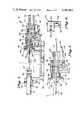
- FIG. 3is an enlarged longitudinal sectional view taken along a plane corresponding to line 3--3 or FIG. 1.
- FIG. 4is an enlarged transverse sectional view taken along a plane corresponding to line 4--4 of FIG. 3.
- FIG. 5is a sectional view similar to FIG. 3, but on a further enlarged scale, showing the retractable part of the holder in its retracted position.
- a cartridge C to be reloadedshown in phantom lines, is releasably held between a pair of companion holders.
- the head end of the cartridgeis urged (by means hereinafter to be described) to engage a substantially conical concave seat 10 that forms the operative part of one of the holders 12.
- the holder 12is an elongated generally cylindrical bar or rod.
- the holder 12slidably fits a bore 14 of a tail bracket 16 of a miniature lathe or tool body 18 and is held in place by a set screw 22.
- the cartridgeis urged against the seat 10 by the aid of a locator or center 24 forming the operative part of the companion holder 26.
- the locator or center 24is convex and substantially conical.
- the holder 26has a cylindrical mounting stem 28 projecting rearwardly.
- the stem 28slidably fits the inboard end of a through bore 30 of a head bracket 32 of the tool body 18 whereby the holder 26 is mounted for limited axial movement toward and away from the companion holder 12.
- the bore 30 in the present instanceis formed by a separate insert 34 of suitable bearing material fitted to a larger bore 36 of the head bracket 32.
- a heavy compression spring 38interposed between the head bracket 32 and the rear surface of the center 26 to urge the holder 26 toward the companion holder 12.
- the center 26enters the mouth of the cartridge C and engages the mouth edges from the inside.
- the cartridgeis urged against the seat 10. Since the holder 26 is free to move axially, it automatically accommodates to the length of the cartridge, which may vary.
- the conical elements 10 and 26together operate by a cam like action to move the cartridge into a coaxial position.
- the primeris removed from its pocket by the aid of a punch rod 40.
- the punch rod 40is guided for axial movement inboard of the head bracket 32 by an elongated aperture 42 in the holder 26.
- the punch rod 40is guided by an anvil 42.
- the anvil 42is attached to the rod by set screws 44.
- the rod guiding function of the anvil 42is performed by a cylindrical neck 46 slidably fitted to the outboard end of the head bracket bore 30.
- the punch rod 40extends through the holder 26 and into the cartridge C. In the position shown in FIGS. 1 and 2, the primer P is about to be dislodged. The forward end of the rod 40 is spaced slightly from the bottom of the primer cup at the flash hole and the anvil 42 is spaced from the outer end surface 48 of the head bracket 32. When the anvil 42 and the punch rod 40 are advanced until the punch rod just contacts the primer cup, the spacing between the anvil and the tool bracket 32 slightly exceeds the axial dimension of the primer to be removed. This is achieved by proper placement of the set screws 44.
- a crank 50In order to exert pressure on the anvil 42, a crank 50 is provided.
- the crankis pivotally mounted on a vertical pin 52 in turn mounted on a lug 54 (FIG. 1) extending laterally of the head bracket 32.
- a handle 56 attached to the crank 50is operative to move the crank in a clockwise direction as shown in FIG. 1 thereby to engage and move the anvil 42.
- the crank 50is slotted (FIG. 4) to allow it to straddle the projecting end of the punch rod 40.
- the punch rod 40has advanced to dislodge the primer.
- a transverse bore 60 in the holder 12 just behind the seat 10allows the dislodged primer P to drop into a pan 62 resting on the bed of the tool body 18.
- the cartridge Cis released by retracting the holder 26. But before the cartridge C can be removed, the punch rod 40 must be withdrawn from the cartridge. This is easily done by using the projecting end of the punch rod 40 or the anvil 42 as a handle.
- a stop 64(FIGS. 1 and 2) mounted at the end of a rod 66 is in the path of retracting movement of the anvil 42. When the anvil 42 engages the stop 64, the forward end of the punch rod has withdrawn inside the holder 26. The center 24 is now withdrawn to release the decapped cartridge C.
- a lever 68(FIG. 1) is provided that is pivotally mounted on a vertical pin 70 in turn mounted on a lateral lug 72 of the tool body 18.
- the operative end of the leveris formed as a yoke 74 (FIGS. 2, 3 and 4) having inwardly projecting pins 76 positioned to engage a peripheral flange 78 at the base of the center or locator 24.
- the leveris moved from a its passive position shown in full lines in FIG. 1 to the phantom line position as indicated by the arrow. This causes the locator 24 to move from the position of FIG. 3 to the retracted position shown in FIG. 4.
- the handle end of the leveris as long as need be to operate the spring 34.
- a stop rod 80(FIGS. 1, 2 and 3) by engagement with the handle 68 prevents the holder 26 from being ejected from the head bracket 32.
- the seat 10accommodates the heads of cartridges of various calibers within a range.
- an adapter 82is provided that fits the opposite end of the holder 12.
- the adapter 82has a mounting stud 84 that fits an end recess 86 of the rod or bar 12.
- Larger caliber cartridges of coursehave larger primer cups to accommodate larger primers.
- a punch rod with a larger diameter headis required.
- a different punch rodmay be provided.
- a punch rod with a larger endis provided by reversing the rod and reattaching the anvil to the opposite end.
- the end of the rod itselfwill contact the primer cup, whereas for the smaller diameter cartridges, a small pin 88 is used for the decapping function.
- the punch rod 40 and anvil 42are easily removed and replaced by angularly moving the crank 50 in a counterclockwise position as shown in FIG. 1 and by temporarily detaching the stop 64. The path of movement of the anvil 42 is then cleared.
- the sizes and shapes of cartridgesvary widely.
- the decapping tool shownis capable of substantially universal use for all cartridges.
Landscapes
- Engineering & Computer Science (AREA)
- Manufacturing & Machinery (AREA)
- General Engineering & Computer Science (AREA)
- Forging (AREA)
Abstract
Description
Claims (5)
Priority Applications (1)
| Application Number | Priority Date | Filing Date | Title |
|---|---|---|---|
| US06/568,345US4549463A (en) | 1984-01-05 | 1984-01-05 | Decapping tool |
Applications Claiming Priority (1)
| Application Number | Priority Date | Filing Date | Title |
|---|---|---|---|
| US06/568,345US4549463A (en) | 1984-01-05 | 1984-01-05 | Decapping tool |
Publications (1)
| Publication Number | Publication Date |
|---|---|
| US4549463Atrue US4549463A (en) | 1985-10-29 |
Family
ID=24270902
Family Applications (1)
| Application Number | Title | Priority Date | Filing Date |
|---|---|---|---|
| US06/568,345Expired - Fee RelatedUS4549463A (en) | 1984-01-05 | 1984-01-05 | Decapping tool |
Country Status (1)
| Country | Link |
|---|---|
| US (1) | US4549463A (en) |
Cited By (3)
| Publication number | Priority date | Publication date | Assignee | Title |
|---|---|---|---|---|
| US20150198429A1 (en)* | 2014-01-10 | 2015-07-16 | Iurie Mirza | Firearm cartridge primer removal tools |
| US20160209193A1 (en)* | 2015-01-15 | 2016-07-21 | Battenfeld Technologies, Inc. | Hand deprimer |
| US10337846B2 (en)* | 2017-05-18 | 2019-07-02 | Rino Pierino TOMASONI | Depriming device and method to deprime firearm cases |
Citations (7)
| Publication number | Priority date | Publication date | Assignee | Title |
|---|---|---|---|---|
| US3134293A (en)* | 1963-02-13 | 1964-05-26 | Richard J Lee | Shell reloaders |
| US3283643A (en)* | 1964-06-19 | 1966-11-08 | Herter Inc S | Decapping and resizing tool |
| US4189980A (en)* | 1978-01-16 | 1980-02-26 | Schaenzer Gordon N | Method and apparatus for reloading a centerfire cartridge |
| US4329906A (en)* | 1980-05-19 | 1982-05-18 | Hornady Manufacturing Company | Reloading apparatus having improved primer mechanism |
| US4332185A (en)* | 1980-04-22 | 1982-06-01 | Hargrove Jasper E | Reloading press priming arm loader and actuator |
| US4385546A (en)* | 1981-10-13 | 1983-05-31 | Lee Richard J | Cartridge reloading dies |
| US4409878A (en)* | 1981-07-22 | 1983-10-18 | Mcclenning Gerald E | Cartridge primer seating tool |
- 1984
- 1984-01-05USUS06/568,345patent/US4549463A/ennot_activeExpired - Fee Related
Patent Citations (7)
| Publication number | Priority date | Publication date | Assignee | Title |
|---|---|---|---|---|
| US3134293A (en)* | 1963-02-13 | 1964-05-26 | Richard J Lee | Shell reloaders |
| US3283643A (en)* | 1964-06-19 | 1966-11-08 | Herter Inc S | Decapping and resizing tool |
| US4189980A (en)* | 1978-01-16 | 1980-02-26 | Schaenzer Gordon N | Method and apparatus for reloading a centerfire cartridge |
| US4332185A (en)* | 1980-04-22 | 1982-06-01 | Hargrove Jasper E | Reloading press priming arm loader and actuator |
| US4329906A (en)* | 1980-05-19 | 1982-05-18 | Hornady Manufacturing Company | Reloading apparatus having improved primer mechanism |
| US4409878A (en)* | 1981-07-22 | 1983-10-18 | Mcclenning Gerald E | Cartridge primer seating tool |
| US4385546A (en)* | 1981-10-13 | 1983-05-31 | Lee Richard J | Cartridge reloading dies |
Cited By (6)
| Publication number | Priority date | Publication date | Assignee | Title |
|---|---|---|---|---|
| US20150198429A1 (en)* | 2014-01-10 | 2015-07-16 | Iurie Mirza | Firearm cartridge primer removal tools |
| US9182203B2 (en)* | 2014-01-10 | 2015-11-10 | Iurie Mirza | Firearm cartridge primer removal tools |
| US20160025472A1 (en)* | 2014-01-10 | 2016-01-28 | Iurie Mirza | Firearm cartridge primer removal tools |
| US20160209193A1 (en)* | 2015-01-15 | 2016-07-21 | Battenfeld Technologies, Inc. | Hand deprimer |
| US9664489B2 (en)* | 2015-01-15 | 2017-05-30 | Battenfeld Technologies, Inc. | Hand deprimer |
| US10337846B2 (en)* | 2017-05-18 | 2019-07-02 | Rino Pierino TOMASONI | Depriming device and method to deprime firearm cases |
Similar Documents
| Publication | Publication Date | Title |
|---|---|---|
| US3818563A (en) | Work-holding chuck and cartridge-case trimmer employing same | |
| US4205547A (en) | Automatic rivet feed | |
| US4620079A (en) | Stud welding device | |
| US4549463A (en) | Decapping tool | |
| US4538934A (en) | Automatic lead advancing mechanism for a mechanical pencil | |
| US5341587A (en) | Ejector and cartridge positioner | |
| US4732073A (en) | Primer pocket swaging device | |
| US4220033A (en) | Blind riveting tool | |
| GB2124955A (en) | Blind riveting tool | |
| US4228606A (en) | Means for mounting cylinder to frame of small hand gun | |
| US9664489B2 (en) | Hand deprimer | |
| US4543741A (en) | Ejector and cartridge positioner for revolvers | |
| JP2641857B2 (en) | Replacement mechanism of holding device at the center of processing machine | |
| US4544295A (en) | Mechanical pencil with self-contained insert | |
| US6032510A (en) | Blind rivet setting tool | |
| US3974736A (en) | Cartridge shell reloading tool | |
| US4924065A (en) | Welding electrode holding device with quick ejection of the worn out electrode | |
| US2984836A (en) | Firing tool with ammunition, more particularly for use as a pin driving tool | |
| US2455826A (en) | Explosively actuated tool | |
| GB1572269A (en) | Jaw assembly for blind riveting apparatus | |
| US3009157A (en) | Explosively actuated tool | |
| PL179594B1 (en) | Writing device | |
| US4809023A (en) | Automatic pencil device for automatic drafting and writing machines | |
| US2136459A (en) | Cartridge loading tool | |
| JP5070096B2 (en) | Work discharge device and machine tool equipped with work discharge device |
Legal Events
| Date | Code | Title | Description |
|---|---|---|---|
| AS | Assignment | Owner name:SYNTEX (U.S.A.) INC., 3401 HILLVIEW AVE., P.O. BOX Free format text:ASSIGNMENT OF ASSIGNORS INTEREST.;ASSIGNORS:VERHEYDEN, JULIEN P. H.;MARTIN, JOHN C.;PRISBE, ERNEST J.;AND OTHERS;REEL/FRAME:004263/0222 Effective date:19840601 Owner name:ALFIELD INDUSTRIES LIMITED, A CORP. OF ONTARIO Free format text:LICENSE;ASSIGNORS:J.N.C. LIMITED;JNC ELECTRONICS INC.;VIDEO MACHINE INC.;AND OTHERS;REEL/FRAME:004264/0004 Effective date:19830203 Owner name:SYNTEX (U.S.A.) INC., A CORP. OF DE,CALIFORNIA Free format text:ASSIGNMENT OF ASSIGNORS INTEREST;ASSIGNORS:VERHEYDEN, JULIEN P. H.;MARTIN, JOHN C.;PRISBE, ERNEST J.;AND OTHERS;REEL/FRAME:004263/0222 Effective date:19840601 | |
| REMI | Maintenance fee reminder mailed | ||
| LAPS | Lapse for failure to pay maintenance fees | ||
| STCH | Information on status: patent discontinuation | Free format text:PATENT EXPIRED DUE TO NONPAYMENT OF MAINTENANCE FEES UNDER 37 CFR 1.362 | |
| FP | Lapsed due to failure to pay maintenance fee | Effective date:19891029 |