US4549188A - Orifice plate for ink jet printer - Google Patents
Orifice plate for ink jet printerDownload PDFInfo
- Publication number
- US4549188A US4549188AUS06/569,354US56935484AUS4549188AUS 4549188 AUS4549188 AUS 4549188AUS 56935484 AUS56935484 AUS 56935484AUS 4549188 AUS4549188 AUS 4549188A
- Authority
- US
- United States
- Prior art keywords
- cylindrical glass
- glass elements
- ceramic sheet
- blank
- face
- Prior art date
- Legal status (The legal status is an assumption and is not a legal conclusion. Google has not performed a legal analysis and makes no representation as to the accuracy of the status listed.)
- Expired - Fee Related
Links
- 239000011521glassSubstances0.000claimsabstractdescription64
- 239000000919ceramicSubstances0.000claimsabstractdescription30
- 238000000034methodMethods0.000claimsabstractdescription16
- KRHYYFGTRYWZRS-UHFFFAOYSA-NFluoraneChemical compoundFKRHYYFGTRYWZRS-UHFFFAOYSA-N0.000claimsdescription27
- 238000000576coating methodMethods0.000claimsdescription14
- 239000011248coating agentSubstances0.000claimsdescription13
- 239000002253acidSubstances0.000claimsdescription11
- 229920001600hydrophobic polymerPolymers0.000claimsdescription6
- 238000007641inkjet printingMethods0.000claimsdescription3
- 239000005361soda-lime glassSubstances0.000claimsdescription3
- 229910052788bariumInorganic materials0.000claimsdescription2
- DSAJWYNOEDNPEQ-UHFFFAOYSA-Nbarium atomChemical compound[Ba]DSAJWYNOEDNPEQ-UHFFFAOYSA-N0.000claimsdescription2
- 239000005388borosilicate glassSubstances0.000claimsdescription2
- 238000004891communicationMethods0.000abstractdescription3
- 239000000976inkSubstances0.000description16
- 238000005530etchingMethods0.000description6
- 239000007787solidSubstances0.000description6
- 239000007788liquidSubstances0.000description3
- VEXZGXHMUGYJMC-UHFFFAOYSA-NHydrochloric acidChemical compoundClVEXZGXHMUGYJMC-UHFFFAOYSA-N0.000description2
- 239000000853adhesiveSubstances0.000description2
- 230000001070adhesive effectEffects0.000description2
- 239000003822epoxy resinSubstances0.000description2
- 239000003365glass fiberSubstances0.000description2
- 239000012633leachableSubstances0.000description2
- 239000000463materialSubstances0.000description2
- 239000000203mixtureSubstances0.000description2
- 230000004048modificationEffects0.000description2
- 238000012986modificationMethods0.000description2
- 229920000647polyepoxidePolymers0.000description2
- PUZPDOWCWNUUKD-UHFFFAOYSA-Msodium fluorideChemical compound[F-].[Na+]PUZPDOWCWNUUKD-UHFFFAOYSA-M0.000description2
- 238000009736wettingMethods0.000description2
- DDFHBQSCUXNBSA-UHFFFAOYSA-N5-(5-carboxythiophen-2-yl)thiophene-2-carboxylic acidChemical compoundS1C(C(=O)O)=CC=C1C1=CC=C(C(O)=O)S1DDFHBQSCUXNBSA-UHFFFAOYSA-N0.000description1
- 238000010306acid treatmentMethods0.000description1
- 230000002411adverseEffects0.000description1
- 230000003139buffering effectEffects0.000description1
- 229920005549butyl rubberPolymers0.000description1
- 229910010293ceramic materialInorganic materials0.000description1
- 238000004140cleaningMethods0.000description1
- 238000001035dryingMethods0.000description1
- 230000000694effectsEffects0.000description1
- 239000000839emulsionSubstances0.000description1
- 238000001704evaporationMethods0.000description1
- 230000008020evaporationEffects0.000description1
- 229910000040hydrogen fluorideInorganic materials0.000description1
- 238000004519manufacturing processMethods0.000description1
- 229910052751metalInorganic materials0.000description1
- 239000002184metalSubstances0.000description1
- 230000009972noncorrosive effectEffects0.000description1
- 230000000737periodic effectEffects0.000description1
- 229920000915polyvinyl chloridePolymers0.000description1
- 239000004800polyvinyl chlorideSubstances0.000description1
- 238000002360preparation methodMethods0.000description1
- 239000011253protective coatingSubstances0.000description1
- 235000013024sodium fluorideNutrition0.000description1
- 239000011775sodium fluorideSubstances0.000description1
- NTHWMYGWWRZVTN-UHFFFAOYSA-Nsodium silicateChemical group[Na+].[Na+].[O-][Si]([O-])=ONTHWMYGWWRZVTN-UHFFFAOYSA-N0.000description1
- 239000002904solventSubstances0.000description1
- 238000003892spreadingMethods0.000description1
- 229910001220stainless steelInorganic materials0.000description1
- 239000010935stainless steelSubstances0.000description1
- 239000000126substanceSubstances0.000description1
Images

Classifications
- B—PERFORMING OPERATIONS; TRANSPORTING
- B41—PRINTING; LINING MACHINES; TYPEWRITERS; STAMPS
- B41J—TYPEWRITERS; SELECTIVE PRINTING MECHANISMS, i.e. MECHANISMS PRINTING OTHERWISE THAN FROM A FORME; CORRECTION OF TYPOGRAPHICAL ERRORS
- B41J2/00—Typewriters or selective printing mechanisms characterised by the printing or marking process for which they are designed
- B41J2/005—Typewriters or selective printing mechanisms characterised by the printing or marking process for which they are designed characterised by bringing liquid or particles selectively into contact with a printing material
- B41J2/01—Ink jet
- B41J2/135—Nozzles
- B41J2/16—Production of nozzles
- B41J2/1621—Manufacturing processes
- B41J2/1623—Manufacturing processes bonding and adhesion
- B—PERFORMING OPERATIONS; TRANSPORTING
- B41—PRINTING; LINING MACHINES; TYPEWRITERS; STAMPS
- B41J—TYPEWRITERS; SELECTIVE PRINTING MECHANISMS, i.e. MECHANISMS PRINTING OTHERWISE THAN FROM A FORME; CORRECTION OF TYPOGRAPHICAL ERRORS
- B41J2/00—Typewriters or selective printing mechanisms characterised by the printing or marking process for which they are designed
- B41J2/005—Typewriters or selective printing mechanisms characterised by the printing or marking process for which they are designed characterised by bringing liquid or particles selectively into contact with a printing material
- B41J2/01—Ink jet
- B41J2/135—Nozzles
- B41J2/16—Production of nozzles
- B41J2/162—Manufacturing of the nozzle plates
- B—PERFORMING OPERATIONS; TRANSPORTING
- B41—PRINTING; LINING MACHINES; TYPEWRITERS; STAMPS
- B41J—TYPEWRITERS; SELECTIVE PRINTING MECHANISMS, i.e. MECHANISMS PRINTING OTHERWISE THAN FROM A FORME; CORRECTION OF TYPOGRAPHICAL ERRORS
- B41J2/00—Typewriters or selective printing mechanisms characterised by the printing or marking process for which they are designed
- B41J2/005—Typewriters or selective printing mechanisms characterised by the printing or marking process for which they are designed characterised by bringing liquid or particles selectively into contact with a printing material
- B41J2/01—Ink jet
- B41J2/135—Nozzles
- B41J2/16—Production of nozzles
- B41J2/1621—Manufacturing processes
- B41J2/1626—Manufacturing processes etching
- B41J2/1629—Manufacturing processes etching wet etching
Definitions
- a common type of orifice plate employed in ink jet printing apparatusconsists of a plurality of glass capillaries bonded vertically in a suitable sheet material such as glass or an epoxy resin. Such sheets are fabricated with relative ease by the techniques disclosed in the Cone U.S. Pat. No. 4,112,436.
- the exposed surfaces of the glass capillaries in orifice plates of the above typelie in the same plane as the supporting sheet.
- the surface of the glass capillaries and the supporting sheetare similar with respect to being wetted by ink jet printing inks.
- the periodic shutdowns of the ink streams through the orifice platecan result in wetting the surfaces surrounding the orifices.
- the spreading of the ink and its subsequent evaporationbuilds up ink solids on the exposed surface of the orifice plate. This buildup of solids adversely affects the subsequent startups of the apparatus.
- the ink solidscan accumulate to the extent that they form a grounding path to the drop charging electrodes. When this occurs, the entire apparatus must be taken out of service for replacement and/or cleaning of the orifice plate.
- the present inventionprovides an orifice plate for an ink jet printer having superior performance characteristics and which can be fabricated with relative ease.
- the orifice plateincludes a plurality of sections of glass capillaries of equal length.
- the glass capillariesare bonded vertically in a ceramic sheet in equidistant linear alignment with the face of one end of each capillary being flush with the bottom (unexposed) face of the ceramic sheet and the other end of the capillary projecting from the top (exposed) face of the ceramic sheet.
- the bottom face of the ceramic sheetis bonded to a rigid support plate having a plurality of openings in communication with each of the glass capillaries.
- the orifice platesare prepared from a blank which includes a plurality of cylindrical glass elements bonded vertically in a ceramic sheet in equidistant linear alignment.
- the cylindrical glass elementsare solid glass fibers including a centrally positioned core of an acid etchable glass.
- a hydrofluoric acid-resistant coatingis deposited on the top surfaces of each of the cylindrical glass elements of the blank.
- a liquid-tight coveris attached to the other surface of the blank.
- the blankis then contacted with a hydrofluoric acid solution to dissolve a portion of the top surface of the ceramic sheet so that the cylindrical glass elements project from the top (exposed) surface of the sheet.
- the hydrofluoric acid-resistant coatingis stripped from the cylindrical glass elements and the cores of said cylindrical glass elements are treated with an acid to dissolve said cores and provide orifices in the cylindrical glass elements.
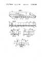
- FIG. 1is a perspective view of an orifice plate of the invention attached to the bottom of an ink reservoir.
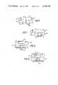
- FIG. 2is a sectional view of a blank employed in the manufacture of the orifice plate of FIG. 1.
- FIG. 3is a sectional view of a segment of the blank of FIG. 2 having a plate positioned thereon to provide a liquid-tight seal over the open end of the blank.
- FIG. 4is a sectional view of a segment of the blank of FIG. 2 with a coating provided over the end of a cylindrical glass element destined to be converted into a glass capillary.
- FIG. 5is a view corresponding to FIG. 4 after a portion of the surface of the ceramic sheet has been etched away.
- FIG. 6is a view corresponding to FIG. 5 after the protective coating has been stripped from the end of the cylindrical glass element.
- FIG. 7shows a view similar to FIG. 6 after the acid soluble glass core has been removed from the cylindrical glass element by an acid treatment.
- FIG. 7Ais a modification of the structure of FIG. 7 in which a hydrophobic polymer coating has been deposited on the exposed outer wall of the glass capillary and the ceramic sheet.
- FIG. 8illustrates the manner in which drops form on the end of the glass capillaries of the orifice plate of the present invention.
- FIG. 9is a representative of the prior art and illustrates the manner in which ink from a glass capillary can spread over an extended area of an orifice plate in which the glass capillary is positioned.
- FIG. 10is a perspective view of a single cylindrical glass element of the type included in the blank illustrated in FIG. 2.
- FIG. 1 of the drawingsshows a perspective view of the orifice plate of the invention in operative assembly with an ink reservoir.
- the orifice plateincludes a ceramic sheet 20 having a plurality of glass capillaries 22 bonded vertically in sheet 20 and being in equidistant linear alignment along the major axis of sheet 20.
- the capillaries 22project outwardly from the exposed face of sheet 20 typically by a distance of about 10 to 25 microns.
- the other ends of capillaries 22are flush with the unseen underside of sheet 20.
- Each of the capillaries 22have a centrally positioned orifice which typically has a diameter in the range of about 0.0005-0.0015 inch (about 10-40 microns).
- the outside diameter of capillaries 22typically is from about three to six times the size of the diameter of the orifice.
- Ceramic sheet 20is bonded to a rigid support sheet 30 which typically is fabricated from stainless steel or other like noncorrosive metal.
- Support plate 30is shown in FIG. 1 as being attached to the bottom of an ink reservoir 100.
- support plate 30contains a plurality of ink reservoirs 34.
- Each reservoir 34communicates with one of the glass capillaries 22 provided in the orifice plate.
- An enlarged view of one reservoir 34 in communication with a single glass capillary 22is shown in FIG. 7.
- the orifice plate of the inventioncan be prepared from a previously formed blank assembly as shown in FIG. 2.
- the ceramic sheet 20has vertically mounted therein cylindrical glass elements 21 destined ultimately to become the glass capillaries 22 shown in FIG. 1.
- cylindrical glass elements 21are glass fibers 21a having a centrally positioned core 21b fabricated from a different type of glass.
- the main body 21ais composed of a hard glass such as a soda-lime glass.
- the center core 21bis composed of an acid soluble or leachable glass such as a barium, lanthanium, or lead borosilicate glass. Glass elements of this type are commercially available from multiple sources, including Galileo Electro Optics. Their method of preparation is shown in the Hicks U.S. Pat. No. 3,294,504 and the Tasswill U.S. Pat. No. 4,212,707.
- the ceramic sheet 20is fabricated from a ceramic material which is more rapidly etched by hydrofluoric acid than the soda-lime glass included in the shell or annulus 21a of cylindrical glass elements 21.
- the product sold under the trade designation PHOTOCERANis well suited for use in the invention.
- the composition and method of preparing this productare shown in U.S. Pat. No. 2,971,853, which description is incorporated herein by reference.
- the ceramic sheet 20is bonded to the rigid support plate 30 by any suitable means such as an epoxy-type adhesive.
- the ceramic sheet 20 having cylindrical glass elements 21 vertically bonded thereincan be prepared by means known in the art.
- One such methodis a minor modification of the method disclosed in the Cone U.S. Pat. No. 4,112,436, the descriptions of which are incorporated herein by reference.
- a series of parallel, equidistant hemispherical or V-shaped groovesare cut in the face of a first ceramic sheet.
- the cylindrical glass elementsare laid in these grooves.
- the groovesare cut so that the lower half of the glass element rests therein with its upper half exposed.
- a second ceramic sheet having like grooves cut in its faceis laid over the glass elements.
- the minor voids between the glass elements and the groovesare filled with a liquid adhesive such as an epoxy resin which then is cured to a solid state.
- the assemblythen is cut orthogonally to the axes of the cylindrical glass elements.
- Other methods for preparing such structureswill be apparent to those skilled in the art.
- the face of each cylindrical glass element 21 in the fully exposed surface of sheet 20is coated with a hydrofluoric acid-resistant coating 36 as best seen in FIG. 4.
- a hydrofluoric acid-resistant coating 36as best seen in FIG. 4.
- Such coatingscan be laid down using known suitable photolithographic or silkscreen techniques.
- the fully exposed face of the rigid support sheet 30is covered with a hydrofluoric acid resistant sheet 38 to provide a liquid-tight seal so that when the assembly is placed in a liquid bath no liquid will enter cavities 34.
- Suitable O-rings 39can be employed in conjunction with sheet 38 to assist in providing such a liquid-tight seal as best seen in FIG. 3.
- the blank of FIG. 2 after being protected as shown in FIGS. 3 and 4is placed in an etching bath to dissolve a portion of the exposed surface of ceramic sheet 20.
- the etching bath employed for this purposewill be an aqueous hydrofluoric acid solution containing appropriate buffering materials such as sodium fluoride or ammonium fluoride.
- the blankwill be maintained in the bath for a period of time sufficient to etch away from about 10 to 25 microns of the surface of ceramic sheet 20.
- the time required in the etching bathwill depend upon both the hydrogen fluoride concentration and the quantity of the surface to be removed.
- concentrated hydrofluoric acidis employed at ambient temperature (20° C.)
- the ceramic surfaceis removed at a rate of about 0.02-0.03 mil (0.001") per second. Under these conditions, an etching period of 20 to 100 seconds may be employed.
- FIG. 5illustrates the effect of the etching bath treatment with the phantom lines representing the portion of surface 20a of sheet 20 which has been removed by the
- the hydrofluoric acid-resistant coating 36is stripped from the ends of the cylindrical glass elements 21 by a suitable solvent.
- the phantom lines in FIG. 6represent the coating 36a that has been removed by the chemical stripping.
- the orifice plateis then treated with an acid solution of a suitable concentration to dissolve the acid leachable core 21b to provide the finished glass capillaries 22 containing an orifice 24 (see FIG. 7).
- the type of acid, the acid concentration, and the temperature employedwill depend largely upon the composition of the glass included in core 21b. It is preferred to use a lanthanium glass as it readily dissolves in 3-5 volume % hydrochloric acid at ambient temperature.
- the etched blank as shown in FIG. 5--before removing the coating 36--is dipped into an emulsion of a hydrophobic polymer such as polyvinyl chloride or a butyl rubber.
- a hydrophobic polymer coatingis formed on the outer exposed surface of capillaries 22 and the face of sheet 20.
- the finished orifice platebears the hydrophobic polymer coating 42 as shown in FIG. 7A.
Landscapes
- Engineering & Computer Science (AREA)
- Manufacturing & Machinery (AREA)
- Particle Formation And Scattering Control In Inkjet Printers (AREA)
- Surface Treatment Of Glass (AREA)
Abstract
Description
Claims (4)
Priority Applications (1)
| Application Number | Priority Date | Filing Date | Title |
|---|---|---|---|
| US06/569,354US4549188A (en) | 1984-01-09 | 1984-01-09 | Orifice plate for ink jet printer |
Applications Claiming Priority (1)
| Application Number | Priority Date | Filing Date | Title |
|---|---|---|---|
| US06/569,354US4549188A (en) | 1984-01-09 | 1984-01-09 | Orifice plate for ink jet printer |
Publications (1)
| Publication Number | Publication Date |
|---|---|
| US4549188Atrue US4549188A (en) | 1985-10-22 |
Family
ID=24275089
Family Applications (1)
| Application Number | Title | Priority Date | Filing Date |
|---|---|---|---|
| US06/569,354Expired - Fee RelatedUS4549188A (en) | 1984-01-09 | 1984-01-09 | Orifice plate for ink jet printer |
Country Status (1)
| Country | Link |
|---|---|
| US (1) | US4549188A (en) |
Cited By (12)
| Publication number | Priority date | Publication date | Assignee | Title |
|---|---|---|---|---|
| US4613875A (en)* | 1985-04-08 | 1986-09-23 | Tektronix, Inc. | Air assisted ink jet head with projecting internal ink drop-forming orifice outlet |
| US4657631A (en)* | 1984-12-28 | 1987-04-14 | Canon Kabushiki Kaisha | Process for producing a liquid jet recording head |
| US4685185A (en)* | 1986-08-29 | 1987-08-11 | Tektronix, Inc. | Method of manufacturing an ink jet head |
| US4728392A (en)* | 1984-04-20 | 1988-03-01 | Matsushita Electric Industrial Co., Ltd. | Ink jet printer and method for fabricating a nozzle member |
| US4728969A (en)* | 1986-07-11 | 1988-03-01 | Tektronix, Inc. | Air assisted ink jet head with single compartment ink chamber |
| US4915718A (en)* | 1988-09-28 | 1990-04-10 | On Target Technology, Inc. | Fabrication of ink jet nozzles and resulting product |
| US5434606A (en)* | 1991-07-02 | 1995-07-18 | Hewlett-Packard Corporation | Orifice plate for an ink-jet pen |
| US5598193A (en)* | 1995-03-24 | 1997-01-28 | Hewlett-Packard Company | Treatment of an orifice plate with self-assembled monolayers |
| US5901425A (en) | 1996-08-27 | 1999-05-11 | Topaz Technologies Inc. | Inkjet print head apparatus |
| US5969733A (en)* | 1996-10-21 | 1999-10-19 | Jemtex Ink Jet Printing Ltd. | Apparatus and method for multi-jet generation of high viscosity fluid and channel construction particularly useful therein |
| US6565760B2 (en)* | 2000-02-28 | 2003-05-20 | Hewlett-Packard Development Company, L.P. | Glass-fiber thermal inkjet print head |
| US20030169315A1 (en)* | 2002-03-07 | 2003-09-11 | Pickrell David J | Micro Fluid Dispensers using Flexible Hollow Glass Fibers |
Citations (8)
| Publication number | Priority date | Publication date | Assignee | Title |
|---|---|---|---|---|
| US3645448A (en)* | 1969-11-17 | 1972-02-29 | Mead Corp | Inlet plate for a coating head |
| US3662399A (en)* | 1969-05-19 | 1972-05-09 | Casio Computer Co Ltd | Nozzle for ink jet and method for manufacturing the same |
| US3776461A (en)* | 1971-10-04 | 1973-12-04 | Casio Computer Co Ltd | Nozzle device for ink jet printing equipments |
| GB1444568A (en)* | 1972-11-24 | 1976-08-04 | Ohno Res & Dev Lab | Recorder unit |
| US4112436A (en)* | 1977-02-24 | 1978-09-05 | The Mead Corporation | Glass nozzle array for an ink jet printer and method of forming same |
| US4122460A (en)* | 1977-08-10 | 1978-10-24 | International Business Machines Corporation | Ink jet nozzle structures |
| US4413268A (en)* | 1980-12-20 | 1983-11-01 | U.S. Philips Corporation | Jet nozzle for an ink jet printer |
| US4429322A (en)* | 1982-02-16 | 1984-01-31 | Mead Corporation | Method of fabricating a glass nozzle array for an ink jet printing apparatus |
- 1984
- 1984-01-09USUS06/569,354patent/US4549188A/ennot_activeExpired - Fee Related
Patent Citations (8)
| Publication number | Priority date | Publication date | Assignee | Title |
|---|---|---|---|---|
| US3662399A (en)* | 1969-05-19 | 1972-05-09 | Casio Computer Co Ltd | Nozzle for ink jet and method for manufacturing the same |
| US3645448A (en)* | 1969-11-17 | 1972-02-29 | Mead Corp | Inlet plate for a coating head |
| US3776461A (en)* | 1971-10-04 | 1973-12-04 | Casio Computer Co Ltd | Nozzle device for ink jet printing equipments |
| GB1444568A (en)* | 1972-11-24 | 1976-08-04 | Ohno Res & Dev Lab | Recorder unit |
| US4112436A (en)* | 1977-02-24 | 1978-09-05 | The Mead Corporation | Glass nozzle array for an ink jet printer and method of forming same |
| US4122460A (en)* | 1977-08-10 | 1978-10-24 | International Business Machines Corporation | Ink jet nozzle structures |
| US4413268A (en)* | 1980-12-20 | 1983-11-01 | U.S. Philips Corporation | Jet nozzle for an ink jet printer |
| US4429322A (en)* | 1982-02-16 | 1984-01-31 | Mead Corporation | Method of fabricating a glass nozzle array for an ink jet printing apparatus |
Non-Patent Citations (1)
| Title |
|---|
| Fillmore et al.; Ink Jet Nozzle Mounting; IBM TDB, vol. 19, No. 11, Apr. 1977, p. 4080.* |
Cited By (17)
| Publication number | Priority date | Publication date | Assignee | Title |
|---|---|---|---|---|
| US4728392A (en)* | 1984-04-20 | 1988-03-01 | Matsushita Electric Industrial Co., Ltd. | Ink jet printer and method for fabricating a nozzle member |
| US4801955A (en)* | 1984-04-20 | 1989-01-31 | Matsushita Electric Industrial Co., Ltd. | Ink jet printer |
| US4801954A (en)* | 1984-04-20 | 1989-01-31 | Matsushita Electric Industrial Co. Ltd. | Ink jet printer |
| US4657631A (en)* | 1984-12-28 | 1987-04-14 | Canon Kabushiki Kaisha | Process for producing a liquid jet recording head |
| US4613875A (en)* | 1985-04-08 | 1986-09-23 | Tektronix, Inc. | Air assisted ink jet head with projecting internal ink drop-forming orifice outlet |
| US4728969A (en)* | 1986-07-11 | 1988-03-01 | Tektronix, Inc. | Air assisted ink jet head with single compartment ink chamber |
| US4685185A (en)* | 1986-08-29 | 1987-08-11 | Tektronix, Inc. | Method of manufacturing an ink jet head |
| US4915718A (en)* | 1988-09-28 | 1990-04-10 | On Target Technology, Inc. | Fabrication of ink jet nozzles and resulting product |
| US5434606A (en)* | 1991-07-02 | 1995-07-18 | Hewlett-Packard Corporation | Orifice plate for an ink-jet pen |
| US5595785A (en)* | 1991-07-02 | 1997-01-21 | Hewlett-Packard Company | Orifice plate for an ink-jet pen |
| US5598193A (en)* | 1995-03-24 | 1997-01-28 | Hewlett-Packard Company | Treatment of an orifice plate with self-assembled monolayers |
| US5901425A (en) | 1996-08-27 | 1999-05-11 | Topaz Technologies Inc. | Inkjet print head apparatus |
| US5969733A (en)* | 1996-10-21 | 1999-10-19 | Jemtex Ink Jet Printing Ltd. | Apparatus and method for multi-jet generation of high viscosity fluid and channel construction particularly useful therein |
| US6106107A (en)* | 1996-10-21 | 2000-08-22 | Jemtex Ink Jet Printing Ltd. | Apparatus and method for multi-jet generation of high viscosity fluid and channel construction particularly useful therein |
| US6565760B2 (en)* | 2000-02-28 | 2003-05-20 | Hewlett-Packard Development Company, L.P. | Glass-fiber thermal inkjet print head |
| US20030169315A1 (en)* | 2002-03-07 | 2003-09-11 | Pickrell David J | Micro Fluid Dispensers using Flexible Hollow Glass Fibers |
| US6752490B2 (en) | 2002-03-07 | 2004-06-22 | David J. Pickrell | Micro fluid dispensers using flexible hollow glass fibers |
Similar Documents
| Publication | Publication Date | Title |
|---|---|---|
| US4549188A (en) | Orifice plate for ink jet printer | |
| US4801954A (en) | Ink jet printer | |
| DE69109447T2 (en) | Thin film thermal inkjet printhead with a plastic nozzle plate and manufacturing process. | |
| JP4263779B2 (en) | Method for attaching an adhesive layer to the surface of a substrate | |
| EP0197723B1 (en) | Thermal ink jet printhead and process therefor | |
| EP0273552A2 (en) | Method of making mandrels for use in a deposition process | |
| US4678529A (en) | Selective application of adhesive and bonding process for ink jet printheads | |
| US4954225A (en) | Method for making nozzle plates | |
| EP0109756B1 (en) | A method of construction of a monolithic ink jet print head | |
| EP0061303A1 (en) | Method of producing an orifice plate | |
| EP0479493A1 (en) | An ink jet printhead | |
| EP0237282A2 (en) | Print head for an ikn jet printer or the like | |
| EP0019385B1 (en) | A planar-faced charge electrode structure for ink jet printers and method of fabricating such a structure | |
| US5461406A (en) | Method and apparatus for elimination of misdirected satellite drops in thermal ink jet printhead | |
| JPH05229128A (en) | Production of ink jet print head | |
| DE69806426T2 (en) | Process for manufacturing an inkjet printhead | |
| WO2004063083A2 (en) | Apparatus for transfer of an array of liquids and methods for manufacturing same | |
| EP0177316A2 (en) | Method for fabricating an ink jet printer nozzle member | |
| JPH08230185A (en) | Inkjet device | |
| JPS61296649A (en) | Display tube | |
| CN104441995B (en) | The manufacture method of liquid ink nozzle, liquid ink nozzle and printing device | |
| DE3122544A1 (en) | Process and apparatus for etching through-holes in glass sheets | |
| JPH0242355B2 (en) | ||
| JP2006175678A (en) | Manufacturing method for nozzle sheet, surface treatment method for nozzle sheet, nozzle sheet, manufacturing method for liquid ejection head, and liquid ejection head | |
| SU965317A1 (en) | Method of manufacturing image converters |
Legal Events
| Date | Code | Title | Description |
|---|---|---|---|
| AS | Assignment | Owner name:MEAD CORPORATION THE, WORLD HEADQUARTERS, COURTHOU Free format text:ASSIGNMENT OF ASSIGNORS INTEREST.;ASSIGNOR:SHACKLETON, CRAIG;REEL/FRAME:004217/0334 Effective date:19831230 | |
| FEPP | Fee payment procedure | Free format text:PAYER NUMBER DE-ASSIGNED (ORIGINAL EVENT CODE: RMPN); ENTITY STATUS OF PATENT OWNER: LARGE ENTITY Free format text:PAYOR NUMBER ASSIGNED (ORIGINAL EVENT CODE: ASPN); ENTITY STATUS OF PATENT OWNER: LARGE ENTITY | |
| AS | Assignment | Owner name:EASTMAN KODAK COMPANY, A CORP. OF NY Free format text:ASSIGNMENT OF ASSIGNORS INTEREST.;ASSIGNOR:MEAD CORPORATION, THE;REEL/FRAME:004918/0208 Effective date:19880531 | |
| FEPP | Fee payment procedure | Free format text:PAYOR NUMBER ASSIGNED (ORIGINAL EVENT CODE: ASPN); ENTITY STATUS OF PATENT OWNER: LARGE ENTITY Free format text:PAYER NUMBER DE-ASSIGNED (ORIGINAL EVENT CODE: RMPN); ENTITY STATUS OF PATENT OWNER: LARGE ENTITY | |
| FPAY | Fee payment | Year of fee payment:4 | |
| REMI | Maintenance fee reminder mailed | ||
| LAPS | Lapse for failure to pay maintenance fees | ||
| FP | Lapsed due to failure to pay maintenance fee | Effective date:19931024 | |
| STCH | Information on status: patent discontinuation | Free format text:PATENT EXPIRED DUE TO NONPAYMENT OF MAINTENANCE FEES UNDER 37 CFR 1.362 |