US4548840A - High speed coating - Google Patents
High speed coatingDownload PDFInfo
- Publication number
- US4548840A US4548840AUS06/608,891US60889184AUS4548840AUS 4548840 AUS4548840 AUS 4548840AUS 60889184 AUS60889184 AUS 60889184AUS 4548840 AUS4548840 AUS 4548840A
- Authority
- US
- United States
- Prior art keywords
- reservoir
- coating
- coating composition
- wall
- liquid
- Prior art date
- Legal status (The legal status is an assumption and is not a legal conclusion. Google has not performed a legal analysis and makes no representation as to the accuracy of the status listed.)
- Expired - Fee Related
Links
- 238000000576coating methodMethods0.000titleclaimsabstractdescription68
- 239000011248coating agentSubstances0.000titleclaimsabstractdescription59
- 238000012546transferMethods0.000claimsabstractdescription27
- 239000008199coating compositionSubstances0.000claimsabstractdescription22
- 238000000034methodMethods0.000claimsabstractdescription11
- 239000007788liquidSubstances0.000claimsdescription24
- 230000008569processEffects0.000claimsdescription10
- 238000002156mixingMethods0.000claimsdescription9
- 239000002904solventSubstances0.000claimsdescription8
- 238000013019agitationMethods0.000claimsdescription5
- 239000000463materialSubstances0.000claimsdescription4
- 230000005484gravityEffects0.000claims1
- 239000000758substrateSubstances0.000claims1
- IJGRMHOSHXDMSA-UHFFFAOYSA-NAtomic nitrogenChemical compoundN#NIJGRMHOSHXDMSA-UHFFFAOYSA-N0.000description6
- 238000010926purgeMethods0.000description5
- 230000008901benefitEffects0.000description4
- ZMXDDKWLCZADIW-UHFFFAOYSA-NN,N-DimethylformamideChemical compoundCN(C)C=OZMXDDKWLCZADIW-UHFFFAOYSA-N0.000description3
- 239000012530fluidSubstances0.000description3
- 229910052757nitrogenInorganic materials0.000description3
- LFQSCWFLJHTTHZ-UHFFFAOYSA-NEthanolChemical compoundCCOLFQSCWFLJHTTHZ-UHFFFAOYSA-N0.000description2
- UQSXHKLRYXJYBZ-UHFFFAOYSA-NIron oxideChemical compound[Fe]=OUQSXHKLRYXJYBZ-UHFFFAOYSA-N0.000description2
- 238000001035dryingMethods0.000description2
- 239000011261inert gasSubstances0.000description2
- 239000000203mixtureSubstances0.000description2
- 230000004044responseEffects0.000description2
- 229920002799BoPETPolymers0.000description1
- 239000005041Mylar™Substances0.000description1
- 230000009471actionEffects0.000description1
- 239000011324beadSubstances0.000description1
- 230000015556catabolic processEffects0.000description1
- 238000006731degradation reactionMethods0.000description1
- 238000013461designMethods0.000description1
- 239000003085diluting agentSubstances0.000description1
- 235000019441ethanolNutrition0.000description1
- 238000001704evaporationMethods0.000description1
- 230000008020evaporationEffects0.000description1
- 230000002349favourable effectEffects0.000description1
- 230000009931harmful effectEffects0.000description1
- 239000002184metalSubstances0.000description1
- 229910052751metalInorganic materials0.000description1
- 238000012986modificationMethods0.000description1
- 230000004048modificationEffects0.000description1
- 239000002245particleSubstances0.000description1
- -1polyethylene terephthalatePolymers0.000description1
- 229920000139polyethylene terephthalatePolymers0.000description1
- 239000005020polyethylene terephthalateSubstances0.000description1
- 230000002028prematureEffects0.000description1
- 238000012545processingMethods0.000description1
- 238000004064recyclingMethods0.000description1
- 239000000523sampleSubstances0.000description1
- 238000007789sealingMethods0.000description1
- 230000009974thixotropic effectEffects0.000description1
- 239000002699waste materialSubstances0.000description1
Images

Classifications
- B—PERFORMING OPERATIONS; TRANSPORTING
- B05—SPRAYING OR ATOMISING IN GENERAL; APPLYING FLUENT MATERIALS TO SURFACES, IN GENERAL
- B05D—PROCESSES FOR APPLYING FLUENT MATERIALS TO SURFACES, IN GENERAL
- B05D1/00—Processes for applying liquids or other fluent materials
- B05D1/28—Processes for applying liquids or other fluent materials performed by transfer from the surfaces of elements carrying the liquid or other fluent material, e.g. brushes, pads, rollers
- B—PERFORMING OPERATIONS; TRANSPORTING
- B05—SPRAYING OR ATOMISING IN GENERAL; APPLYING FLUENT MATERIALS TO SURFACES, IN GENERAL
- B05C—APPARATUS FOR APPLYING FLUENT MATERIALS TO SURFACES, IN GENERAL
- B05C1/00—Apparatus in which liquid or other fluent material is applied to the surface of the work by contact with a member carrying the liquid or other fluent material, e.g. a porous member loaded with a liquid to be applied as a coating
- B05C1/04—Apparatus in which liquid or other fluent material is applied to the surface of the work by contact with a member carrying the liquid or other fluent material, e.g. a porous member loaded with a liquid to be applied as a coating for applying liquid or other fluent material to work of indefinite length
- B05C1/08—Apparatus in which liquid or other fluent material is applied to the surface of the work by contact with a member carrying the liquid or other fluent material, e.g. a porous member loaded with a liquid to be applied as a coating for applying liquid or other fluent material to work of indefinite length using a roller or other rotating member which contacts the work along a generating line
- B05C1/0813—Apparatus in which liquid or other fluent material is applied to the surface of the work by contact with a member carrying the liquid or other fluent material, e.g. a porous member loaded with a liquid to be applied as a coating for applying liquid or other fluent material to work of indefinite length using a roller or other rotating member which contacts the work along a generating line characterised by means for supplying liquid or other fluent material to the roller
- B—PERFORMING OPERATIONS; TRANSPORTING
- B05—SPRAYING OR ATOMISING IN GENERAL; APPLYING FLUENT MATERIALS TO SURFACES, IN GENERAL
- B05C—APPARATUS FOR APPLYING FLUENT MATERIALS TO SURFACES, IN GENERAL
- B05C1/00—Apparatus in which liquid or other fluent material is applied to the surface of the work by contact with a member carrying the liquid or other fluent material, e.g. a porous member loaded with a liquid to be applied as a coating
- B05C1/04—Apparatus in which liquid or other fluent material is applied to the surface of the work by contact with a member carrying the liquid or other fluent material, e.g. a porous member loaded with a liquid to be applied as a coating for applying liquid or other fluent material to work of indefinite length
- B05C1/08—Apparatus in which liquid or other fluent material is applied to the surface of the work by contact with a member carrying the liquid or other fluent material, e.g. a porous member loaded with a liquid to be applied as a coating for applying liquid or other fluent material to work of indefinite length using a roller or other rotating member which contacts the work along a generating line
- B05C1/0817—Apparatus in which liquid or other fluent material is applied to the surface of the work by contact with a member carrying the liquid or other fluent material, e.g. a porous member loaded with a liquid to be applied as a coating for applying liquid or other fluent material to work of indefinite length using a roller or other rotating member which contacts the work along a generating line characterised by means for removing partially liquid or other fluent material from the roller, e.g. scrapers
- B—PERFORMING OPERATIONS; TRANSPORTING
- B05—SPRAYING OR ATOMISING IN GENERAL; APPLYING FLUENT MATERIALS TO SURFACES, IN GENERAL
- B05C—APPARATUS FOR APPLYING FLUENT MATERIALS TO SURFACES, IN GENERAL
- B05C1/00—Apparatus in which liquid or other fluent material is applied to the surface of the work by contact with a member carrying the liquid or other fluent material, e.g. a porous member loaded with a liquid to be applied as a coating
- B05C1/04—Apparatus in which liquid or other fluent material is applied to the surface of the work by contact with a member carrying the liquid or other fluent material, e.g. a porous member loaded with a liquid to be applied as a coating for applying liquid or other fluent material to work of indefinite length
- B05C1/08—Apparatus in which liquid or other fluent material is applied to the surface of the work by contact with a member carrying the liquid or other fluent material, e.g. a porous member loaded with a liquid to be applied as a coating for applying liquid or other fluent material to work of indefinite length using a roller or other rotating member which contacts the work along a generating line
- B05C1/0826—Apparatus in which liquid or other fluent material is applied to the surface of the work by contact with a member carrying the liquid or other fluent material, e.g. a porous member loaded with a liquid to be applied as a coating for applying liquid or other fluent material to work of indefinite length using a roller or other rotating member which contacts the work along a generating line the work being a web or sheets
- B05C1/083—Apparatus in which liquid or other fluent material is applied to the surface of the work by contact with a member carrying the liquid or other fluent material, e.g. a porous member loaded with a liquid to be applied as a coating for applying liquid or other fluent material to work of indefinite length using a roller or other rotating member which contacts the work along a generating line the work being a web or sheets being passed between the coating roller and one or more backing rollers
Definitions
- This inventionrelates to improved systems for applying liquid coatings to sheet products, particularly with the use of a transfer roll intermediate a coating reservoir and the sheet to be coated.
- U.S. Pat. No. 4,387,124describes a coating apparatus using a geometrical flow-divider to aid the distribution of a non-Newtonian fluid onto a web while a resilient seal means was used to maintain a small amount of liquid coating close to the web being coated:
- U.S. Pat. No. 3,533,833also discloses a somewhat similar apparatus wherein a coating is applied directly to a web from a reservoir.
- Another object of the inventionis to provide an improved system for applying very thin coatings (say, of the order of about 100 microinch, or 2 to 3 micrometers of dry coating) and, more particularly, thin coatings comprising volatile liquids.
- Another object of the inventionis to provide a coating system that is maintained in an easily cleanable condition.
- a coating reservoirwhich, among other things, utilizes as one wall thereof, a moving object to be coated as a major source of kinetic energy to impart a uniform mixing energy across the entire width of the reservoir. This feature avoids the need to provide complex flow-distributing means.
- a doctor bladeEnclosed within an enclosure, or cover, of the reservoir is a doctor blade which is used to scrape off coating from that portion of the reservoir wall which has been coated and moves upwardly out of the coating liquid. Coating fluid dropping back into the reservoir further aids the aforesaid mixing action.
- the reservoirwill be formed of a rotating transfer roll which, after the proper amount of coating is applied thereto, transfers coating to a web to be coated.
- the coating system of the inventionallows, the coating composition to be transferred on a transfer roll to a film to be coated without any degradation to the coating caused by excessive localized concentration of the film during its transit from reservoir to the surface to be ultimately coated. This is true even at very high coating-line speeds; even when using rather volatile solvents as coating composition vehicle; and even with very thin coatings being carried on the transfer drum.
- the dwell time of doctored coating on the transfer rollless than about 0.5 second before it is tranferred to the ultimate web--after a web of a biaxially oriented film material such as the polyethylene terephthalate film sold by E.I. DuPont unde the name Mylar.
- the dwell timeis as low as 0.1 second.
- a surface initially to be coatedi.e. that surface forming part of the coating reservoir (usually, a transfer roll) is preferably moving upwardly and pulling coating with it.
- the roll surfacehas a vector moving inwardly towards the back of the reservoir, i.e. the wall of the reservoir opposed to the moving wall formed by the transfer roll. This is achieved by placing the coating reservoir below the horizontal diameter of the transfer roll being coated. Such an arrangement grossly simplifies the seal design of the reservoir.
- light syrup-like coatingscan be used with clearances as low as about 0.005-0.010 inch between a drum and the reservoir structure.
- thixotropic compositionswill offer a particularly advantageous combination of properties in that they allow good mixing and also, allow better sealing away from more highly agitated portions of the reservoir.
- coating reservoiras used in this application is meant to describe a container holding a substantial supply of liquid coating solution enclosed therein. That term is not intended to describe a mere nip between a surface to be coated and a feed device in which a bead of liquid resides briefly before being carried away on a coated surface.
- a typical contact perimeter between the transfer roll and the reservoir liquidis about two to five inches high and as wide as the coated surface, say about two to four feet. In general, it is preferred that the contact height exceed the average dimension of the reservoir extending from the transfer roll, through the liquid, to the rear wall of the reservoir most remote from the tranfer roll. Such dimensional relationships facilitate the degree of mixing in the reservoir.
- the transfer rollconveniently has a surface which is slightly textured as is known to the gravure-art roll and which promotes the distribution of ultra-thin coatings.
- this systemIt is preferred to operate this system under a nitrogen purge. Although such purge systems are not new, in the present systems, it has the advantage of assuring that the continuous operation of the equipment may be achieved without any concern for waste or the quality of recycled material.
- the nitrogencarries a substantial quantity of solvent to further avoid an evaporation of solvent in the system.
- Fresh coating solutionwhen needed, is pumped into the reservoir in response to a constant-level control system like. It has been found desirable to have a variable level control system, i.e. one which can be utilized to set a wide range of desirable "mixing perimeters" between coating solution and roll by varying the height of the solution in the reservoir.
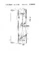
- FIG. 1is an elevation, somewhat schematic which shows the essentials of the coating system of the invention.
- FIG. 2is an elevation, somewhat schematic, taken at right angles to FIG. 1.
- a portion 10 of a web-coating linecomprises a web 12 being coated while being held by a rotating backing roll 14 against a transfer roll 16.
- Transfer roll 16forms one wall 18 of a reservoir 20.
- Wall 18will be seen to be constantly moving up and towards the rear wall structure 19 of the reservoir 20, thereby forming means to constantly pull a substantial portion of coating solution upwardly along its face and aid in circulating the coating solution. Simultaneous, a vector of the circulating force is directed towards the back of the reservoir.
- Liquidwill be carried upwardly on wall 18 in quantities of, typically, 2 to 5 times the amount of coating liquid that is actually required for coating.
- the excess liquidis removed by a coating knife 24 and a deflector blade 25. It falls into the reservoir 20, preferably into that part of the reservoir wherein there is an upward pull on the liquid being exerted by the moving wall. It thereby contributes further to the agitation and mixing therein.
- the average vertical distance of the reservoiri.e. the contact height of liquid and moving wall 18, exceeds the average distance between the moving wall 18 and the backward wall 26. This assures mixing throughout the reservoir.
- inert-gas purge means 28such as an elongate conduit 29.
- the purgeis convenient nitrogen and it is recommended that it contain with a substantial amount of vapor of the more volatile solvent components of the coating solution.
- This purgeis placed between roll 16 and the doctor blade-carrying structure 32. It is further noted that the entire structure shown is preferably enclosed within a sheet metal hood and this hood, too, is purged with a positive-pressure inert-gas bearing sufficient solvent vapor to eliminate any drying and crusting of composition anywhere on the apparatus.
- a capacitance-resistance-type level detector(proximity detector). Its probe 36 is placed in the reservoir.
- This type of level detectora type well known in the art, allows the apparatus to be run at different liquid heights. Conduits and pumps for filling the reservoir in response to the level-control system are not shown because they form no part of the invention and are readily understood by any skilled in the art.
Landscapes
- Application Of Or Painting With Fluid Materials (AREA)
- Coating Apparatus (AREA)
Abstract
Description
Claims (19)
Priority Applications (1)
| Application Number | Priority Date | Filing Date | Title |
|---|---|---|---|
| US06/608,891US4548840A (en) | 1984-06-15 | 1984-06-15 | High speed coating |
Applications Claiming Priority (1)
| Application Number | Priority Date | Filing Date | Title |
|---|---|---|---|
| US06/608,891US4548840A (en) | 1984-06-15 | 1984-06-15 | High speed coating |
Publications (1)
| Publication Number | Publication Date |
|---|---|
| US4548840Atrue US4548840A (en) | 1985-10-22 |
Family
ID=24438498
Family Applications (1)
| Application Number | Title | Priority Date | Filing Date |
|---|---|---|---|
| US06/608,891Expired - Fee RelatedUS4548840A (en) | 1984-06-15 | 1984-06-15 | High speed coating |
Country Status (1)
| Country | Link |
|---|---|
| US (1) | US4548840A (en) |
Cited By (14)
| Publication number | Priority date | Publication date | Assignee | Title |
|---|---|---|---|---|
| US4793899A (en)* | 1987-07-23 | 1988-12-27 | Beloit Corporation | Coating press apparatus using short dwell coaters |
| US4928622A (en)* | 1988-02-12 | 1990-05-29 | Ab Akerlund & Rausing | Machine for applying adhesive to an elongate sheet material |
| US5230920A (en)* | 1990-10-23 | 1993-07-27 | Kabushiki Kaisha Toshiba | Method of coating sensitizing solution on metal plate for use in manufacture of color cathode ray tube and coating apparatus |
| US5266114A (en)* | 1990-06-07 | 1993-11-30 | Yasui Seiki Co., Ltd. | Apparatus for supplying gravure coating material |
| DE4414949A1 (en)* | 1994-04-28 | 1995-11-02 | Voith Gmbh J M | Device for applying at least one liquid medium to a running web of material |
| US5560294A (en)* | 1994-01-18 | 1996-10-01 | Man Roland Druckmaschinen Ag | Device for inking a screen roller |
| EP0857517A4 (en)* | 1996-05-29 | 1999-05-19 | Nof Corp | Method of forming coating film |
| FR2792448A1 (en)* | 1999-04-13 | 2000-10-20 | Sony Corp | Fabrication of a support for magnetic recording, particularly magnetic recording tape |
| JP3435242B2 (en) | 1994-01-31 | 2003-08-11 | フォイト ズルツァー パピエールマシーネン ゲーエムベーハー | Method and apparatus for coating fibrous web |
| US20050163934A1 (en)* | 2004-01-27 | 2005-07-28 | Eastman Kodak Company | Gravure method and apparatus for coating a liquid reactive to the atmosphere |
| US20060231021A1 (en)* | 2005-04-14 | 2006-10-19 | Hamilton Sundstrand Corporation | Apparatus for applying thin coating |
| US20070269602A1 (en)* | 2006-05-18 | 2007-11-22 | Leszek Poletek | Coating system for metal strips and method for producing metal strips partially coated on one side |
| CN105381922A (en)* | 2015-11-30 | 2016-03-09 | 芜湖恒美电热器具有限公司 | Automatic gluing device for positive temperature coefficient (PTC) radiating tubes |
| JP2017221865A (en)* | 2016-06-13 | 2017-12-21 | 富士機械工業株式会社 | Gravure coating device |
Citations (7)
| Publication number | Priority date | Publication date | Assignee | Title |
|---|---|---|---|---|
| US3081191A (en)* | 1959-02-18 | 1963-03-12 | Mead Corp | Doctor blade |
| FR2425277A1 (en)* | 1978-05-11 | 1979-12-07 | Seita | Feeding viscous prods. to applicator roller - by adjustable blade forming angle holding reserve fed from reservoir, eliminating harmful mixing effects |
| US4245583A (en)* | 1977-12-19 | 1981-01-20 | Polytype Ag | Mechanism to transfer a viscous coating medium |
| US4345543A (en)* | 1978-02-23 | 1982-08-24 | International Business Machines Corporation | Apparatus for forming a coating on a substrate |
| US4400953A (en)* | 1979-09-01 | 1983-08-30 | Eduard Kusters | Apparatus for the continuous treatment of textile and similar webs of material |
| US4442144A (en)* | 1980-11-17 | 1984-04-10 | International Business Machines Corporation | Method for forming a coating on a substrate |
| US4475478A (en)* | 1983-04-08 | 1984-10-09 | International Business Machines Corporation | Coating apparatus |
- 1984
- 1984-06-15USUS06/608,891patent/US4548840A/ennot_activeExpired - Fee Related
Patent Citations (7)
| Publication number | Priority date | Publication date | Assignee | Title |
|---|---|---|---|---|
| US3081191A (en)* | 1959-02-18 | 1963-03-12 | Mead Corp | Doctor blade |
| US4245583A (en)* | 1977-12-19 | 1981-01-20 | Polytype Ag | Mechanism to transfer a viscous coating medium |
| US4345543A (en)* | 1978-02-23 | 1982-08-24 | International Business Machines Corporation | Apparatus for forming a coating on a substrate |
| FR2425277A1 (en)* | 1978-05-11 | 1979-12-07 | Seita | Feeding viscous prods. to applicator roller - by adjustable blade forming angle holding reserve fed from reservoir, eliminating harmful mixing effects |
| US4400953A (en)* | 1979-09-01 | 1983-08-30 | Eduard Kusters | Apparatus for the continuous treatment of textile and similar webs of material |
| US4442144A (en)* | 1980-11-17 | 1984-04-10 | International Business Machines Corporation | Method for forming a coating on a substrate |
| US4475478A (en)* | 1983-04-08 | 1984-10-09 | International Business Machines Corporation | Coating apparatus |
Cited By (17)
| Publication number | Priority date | Publication date | Assignee | Title |
|---|---|---|---|---|
| US4793899A (en)* | 1987-07-23 | 1988-12-27 | Beloit Corporation | Coating press apparatus using short dwell coaters |
| US4928622A (en)* | 1988-02-12 | 1990-05-29 | Ab Akerlund & Rausing | Machine for applying adhesive to an elongate sheet material |
| US5266114A (en)* | 1990-06-07 | 1993-11-30 | Yasui Seiki Co., Ltd. | Apparatus for supplying gravure coating material |
| US5230920A (en)* | 1990-10-23 | 1993-07-27 | Kabushiki Kaisha Toshiba | Method of coating sensitizing solution on metal plate for use in manufacture of color cathode ray tube and coating apparatus |
| US5560294A (en)* | 1994-01-18 | 1996-10-01 | Man Roland Druckmaschinen Ag | Device for inking a screen roller |
| JP3435242B2 (en) | 1994-01-31 | 2003-08-11 | フォイト ズルツァー パピエールマシーネン ゲーエムベーハー | Method and apparatus for coating fibrous web |
| DE4414949A1 (en)* | 1994-04-28 | 1995-11-02 | Voith Gmbh J M | Device for applying at least one liquid medium to a running web of material |
| US5685909A (en)* | 1994-04-28 | 1997-11-11 | Voith Sulzer Papiermaschinen Gmbh | Device for producing paper webs coated on both sides |
| EP0857517A4 (en)* | 1996-05-29 | 1999-05-19 | Nof Corp | Method of forming coating film |
| FR2792448A1 (en)* | 1999-04-13 | 2000-10-20 | Sony Corp | Fabrication of a support for magnetic recording, particularly magnetic recording tape |
| US6296898B1 (en)* | 1999-04-13 | 2001-10-02 | Sony Corporation | Method and system for manufacturing magnetic recording medium |
| US20050163934A1 (en)* | 2004-01-27 | 2005-07-28 | Eastman Kodak Company | Gravure method and apparatus for coating a liquid reactive to the atmosphere |
| US20060231021A1 (en)* | 2005-04-14 | 2006-10-19 | Hamilton Sundstrand Corporation | Apparatus for applying thin coating |
| US8312834B2 (en) | 2005-04-14 | 2012-11-20 | Hamilton Sundstrand Corporation | Apparatus for applying thin coating |
| US20070269602A1 (en)* | 2006-05-18 | 2007-11-22 | Leszek Poletek | Coating system for metal strips and method for producing metal strips partially coated on one side |
| CN105381922A (en)* | 2015-11-30 | 2016-03-09 | 芜湖恒美电热器具有限公司 | Automatic gluing device for positive temperature coefficient (PTC) radiating tubes |
| JP2017221865A (en)* | 2016-06-13 | 2017-12-21 | 富士機械工業株式会社 | Gravure coating device |
Similar Documents
| Publication | Publication Date | Title |
|---|---|---|
| US4548840A (en) | High speed coating | |
| EP0000241B1 (en) | Process and apparatus for coating a web | |
| US4538541A (en) | Method of and apparatus for applying a uniform layer of liquid to a surface | |
| JPS6138687Y2 (en) | ||
| EP0436172A1 (en) | Coating apparatus | |
| US3143438A (en) | Apparatus for coating web material | |
| US5628827A (en) | Non-recirculating, die supplied doctored roll coater with solvent addition | |
| KR20000070307A (en) | Die edge cleaning system | |
| US4780336A (en) | Doctor blade for paper coater | |
| US5567479A (en) | Method and device for coating the face of a roll in a film size press | |
| EP0714325B1 (en) | Non-recirculating, die supplied doctored roll coater with solvent addition | |
| US3244552A (en) | Process for coating film | |
| FI63275C (en) | PROCEDURE FOR THE CONFORMITY OF CONSTRUCTION OF BANDMATERIAL MEDHJAELP AV EN BESTRYKNINGSVALS | |
| EP0822007A2 (en) | Improved high speed coating starts | |
| US4125641A (en) | Method for applying a coating composition onto a moving paperweb | |
| JP2001000899A (en) | Coating method and device | |
| US3565662A (en) | Strip coating method and apparatus | |
| JP2667032B2 (en) | Roller curtain coating method | |
| JPH05220430A (en) | Coating device | |
| JPS63143963A (en) | Roll coater type coating device | |
| JPH081061A (en) | Curtain coating method and apparatus | |
| JPS6223626B2 (en) | ||
| JPS605256A (en) | Cylinder coating apparatus | |
| JPS62193675A (en) | Coating method | |
| JPS61216771A (en) | Method for coating aqueous dispersion liquid |
Legal Events
| Date | Code | Title | Description |
|---|---|---|---|
| AS | Assignment | Owner name:GRAHAM MAGNETICS INCORPORATED 6625 INDUSTRIAL PARK Free format text:ASSIGNMENT OF ASSIGNORS INTEREST.;ASSIGNORS:STATES, KENNETH H.;SMITH, WALTER W.;REEL/FRAME:004295/0637 Effective date:19840430 | |
| FEPP | Fee payment procedure | Free format text:PAYOR NUMBER ASSIGNED (ORIGINAL EVENT CODE: ASPN); ENTITY STATUS OF PATENT OWNER: LARGE ENTITY | |
| FPAY | Fee payment | Year of fee payment:4 | |
| SULP | Surcharge for late payment | ||
| AS | Assignment | Owner name:CARLISLE MEMORY PRODUCTS GROUP INCORPORATED Free format text:CHANGE OF NAME;ASSIGNOR:GRAHAM MAGNETICS INCORPORATED;REEL/FRAME:005267/0659 Effective date:19890123 | |
| AS | Assignment | Owner name:CHEMICAL BANK, AS AGENT Free format text:SECURITY INTEREST;ASSIGNOR:GRAHAM MAGNETICS, INC. (FORMERLY KNOWN AS GRAHAM ASSET CORP. ) A CORP. OF DELAWARE;REEL/FRAME:006182/0811 Effective date:19920630 | |
| AS | Assignment | Owner name:GRAHAM MAGNETICS INC. (FORMERLY KNOWN AS GRAHAM AS Free format text:ASSIGNMENT OF ASSIGNORS INTEREST.;ASSIGNOR:CARLISLE MEMORY PRODUCTS GROUP INCORPORATED;REEL/FRAME:006232/0480 Effective date:19920630 | |
| REMI | Maintenance fee reminder mailed | ||
| LAPS | Lapse for failure to pay maintenance fees | ||
| FP | Lapsed due to failure to pay maintenance fee | Effective date:19931024 | |
| STCH | Information on status: patent discontinuation | Free format text:PATENT EXPIRED DUE TO NONPAYMENT OF MAINTENANCE FEES UNDER 37 CFR 1.362 |