US4548505A - Sensor for spectral analyzer for living tissues - Google Patents
Sensor for spectral analyzer for living tissuesDownload PDFInfo
- Publication number
- US4548505A US4548505AUS06/369,767US36976782AUS4548505AUS 4548505 AUS4548505 AUS 4548505AUS 36976782 AUS36976782 AUS 36976782AUS 4548505 AUS4548505 AUS 4548505A
- Authority
- US
- United States
- Prior art keywords
- sensor
- holder
- probe
- reflector
- fiber
- Prior art date
- Legal status (The legal status is an assumption and is not a legal conclusion. Google has not performed a legal analysis and makes no representation as to the accuracy of the status listed.)
- Expired - Fee Related
Links
Images

Classifications
- A—HUMAN NECESSITIES
- A61—MEDICAL OR VETERINARY SCIENCE; HYGIENE
- A61B—DIAGNOSIS; SURGERY; IDENTIFICATION
- A61B5/00—Measuring for diagnostic purposes; Identification of persons
- A61B5/145—Measuring characteristics of blood in vivo, e.g. gas concentration or pH-value ; Measuring characteristics of body fluids or tissues, e.g. interstitial fluid or cerebral tissue
- A61B5/1455—Measuring characteristics of blood in vivo, e.g. gas concentration or pH-value ; Measuring characteristics of body fluids or tissues, e.g. interstitial fluid or cerebral tissue using optical sensors, e.g. spectral photometrical oximeters
- A—HUMAN NECESSITIES
- A61—MEDICAL OR VETERINARY SCIENCE; HYGIENE
- A61B—DIAGNOSIS; SURGERY; IDENTIFICATION
- A61B5/00—Measuring for diagnostic purposes; Identification of persons
- A61B5/68—Arrangements of detecting, measuring or recording means, e.g. sensors, in relation to patient
- A61B5/6801—Arrangements of detecting, measuring or recording means, e.g. sensors, in relation to patient specially adapted to be attached to or worn on the body surface
- A61B5/6843—Monitoring or controlling sensor contact pressure
- G—PHYSICS
- G01—MEASURING; TESTING
- G01N—INVESTIGATING OR ANALYSING MATERIALS BY DETERMINING THEIR CHEMICAL OR PHYSICAL PROPERTIES
- G01N21/00—Investigating or analysing materials by the use of optical means, i.e. using sub-millimetre waves, infrared, visible or ultraviolet light
- G01N21/84—Systems specially adapted for particular applications
- G01N21/85—Investigating moving fluids or granular solids
- G01N21/8507—Probe photometers, i.e. with optical measuring part dipped into fluid sample
Definitions
- the present inventionrelates to a sensor for use with a spectral analyzer for living tissues.
- the sensoris capable of obtaining data in a timely manner at constant pressure and can be handled easily with increased safety and reliability.
- Spectral analysis of living tissuesis conventionally performed by one of two methods: (1) the tip of a bundle of fibers connected to the spectral analyzer is inserted into the human body either directly or with the aid of a laparoscope or a fiberscope, and while the pressure applied to the tissue is controlled with one hand, the analyzer is switched on and off with the other hand to obtain data; and (2) the tip of bundle of fibers connected to the spectral analyzer is inserted into a spring-loaded holder in the form of an elongated tube with a contact provided between the holder and fiber bundle and connected to the switching circuit in the analyzer, and the holder is inserted in the human body until the fiber bundle whose tip is being pressed against the tissue is retracted by a predetermined distance against the force of the spring, whereupon the contact is closed to start the collection of the necessary data.
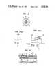
- FIG. 1is a front view, partly in section, of the essential components of the sensor of the present invention
- FIG. 2is a cross section showing one end of the sensor of FIG. 1;
- FIGS. 3(a) and 3(b)are circuit diagrams of the light source and photoelectric converter, respectively;
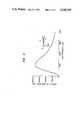
- FIG. 4is a graph illustrating the measurement of the reflected light intensity vs. gap profile of the sensor.
- the probe 5is capable of limited axial movement relative to the holder 3, limited by means of the engagement between annular projections 10 and 11.
- the probe 5has a relatively small size and is made of a light material.
- the fiber 8consists of two independent fibers 12 and 13, one for transmitting light and the other for receiving light.
- the fibermay be a single fiber including a half mirror at a branch for transmitting and receiving light.
- the light transmitting fiber 12is supplied with light of a given intensity from a light source 14 through a lens 15, and the light coming from the light receiving fiber 13 is converted to an electric current in a photoelectric converter 16 and compared with a reference value whereby the switch circuit 17 may be opened or closed.
- FIG. 3(a)is a circuit diagram for the light source 14 and FIG. 3(b) is a circuit diagram for the photoelectric converter 16.
- the light source 14comprises a light-emitting diode (LED) which is connected to a power source through a resistor and which emits light of a given intensity which enters the light transmitting fiber 12 through the lens. The light is reflected by the annular reflector 6 and travels back through the light receiving fiber 13. Thereupon, the light is converted to an electric current by a photodiode (PD), whose output is applied to an operational amplifier 18.
- the operational amplifier 18operates to convert an input current from the photodiode (PD) to a voltage signal, and the switch circuit 17 of the spectral analyzer is actuated in response to predetermined variations in the voltage signal.
- the sensor of the present inventionhaving the above described arrangement is used as follows.
- the holder 3 or sheath 2is held in one hand and the probe 5 is inserted into the human body to press the outer surface of the reflector 6 against the tissue.
- the probe 5is retracted against the force of the spring 7, and when the distance between the reflector 6 and the tip of the bundled fiber 8 becomes smaller than a given value, the intensity of the light sent back through a feedback loop consisting of the light source 14, the light transmitting fiber 12, the reflector 6 and the light receiving fiber 13 becomes smaller than a predetermined level, to thereby close the switch circuit 17 of the spectral analyzer.
- a measurement of the light intensity vs. gap profileis shown in FIG. 4.
- the relatively light probe 5is supported by the spring 7 against the holder 3, so that the pressure applied to the tissue remains constant without fluctuation even if the angle at which the sensor is set on the body is varied.
- the necessary datacan be obtained by simply pressing the sensor against the tissue with one hand, which not only improves the operability of the sensor but also achieves timely collection of data.
- the signals for turning on and off the switch 17are fed optically through the optical fiber 8, making the sensor safer to use yet trouble-free.
- FIG. 5A modification of the sensor of the present invention is shown in FIG. 5 wherein the holder 3' and probe 5' are modified as shown, and the reflector 6' is positioned on the rear end of the probe.
- the light transmitting/receiving fiber 8is positioned adjacent the bundled fiber 1 with its tip facing reflector 6'. This modified arrangement performs equally as well as the arrangement shown in FIG. 1.
Landscapes
- Health & Medical Sciences (AREA)
- Life Sciences & Earth Sciences (AREA)
- Physics & Mathematics (AREA)
- Pathology (AREA)
- General Health & Medical Sciences (AREA)
- Surgery (AREA)
- Public Health (AREA)
- Engineering & Computer Science (AREA)
- Biomedical Technology (AREA)
- Heart & Thoracic Surgery (AREA)
- Medical Informatics (AREA)
- Molecular Biology (AREA)
- Veterinary Medicine (AREA)
- Animal Behavior & Ethology (AREA)
- Biophysics (AREA)
- Spectroscopy & Molecular Physics (AREA)
- Optics & Photonics (AREA)
- Chemical & Material Sciences (AREA)
- Analytical Chemistry (AREA)
- Biochemistry (AREA)
- General Physics & Mathematics (AREA)
- Immunology (AREA)
- Investigating Or Analysing Materials By Optical Means (AREA)
- Measuring And Recording Apparatus For Diagnosis (AREA)
- Endoscopes (AREA)
Abstract
Description
The present invention relates to a sensor for use with a spectral analyzer for living tissues. The sensor is capable of obtaining data in a timely manner at constant pressure and can be handled easily with increased safety and reliability.
Spectral analysis of living tissues (the stomach, intestines, skins, tooth sockets and other parts of the living organism) is conventionally performed by one of two methods: (1) the tip of a bundle of fibers connected to the spectral analyzer is inserted into the human body either directly or with the aid of a laparoscope or a fiberscope, and while the pressure applied to the tissue is controlled with one hand, the analyzer is switched on and off with the other hand to obtain data; and (2) the tip of bundle of fibers connected to the spectral analyzer is inserted into a spring-loaded holder in the form of an elongated tube with a contact provided between the holder and fiber bundle and connected to the switching circuit in the analyzer, and the holder is inserted in the human body until the fiber bundle whose tip is being pressed against the tissue is retracted by a predetermined distance against the force of the spring, whereupon the contact is closed to start the collection of the necessary data.
In the spectral analysis of living tissues, data must be obtained as soon as the tip of the bundle of fibers contacts the tissue and before any undesired change occurs in the living tissue, and the pressure applied to the tissue by the tip of the fiber bundle is desirably held constant to maintain the local hemostatic effect. These requirements are however not fully met by either of the two conventional methods. According to the first method, there often occurs a time lag in obtaining the necessary data because it is difficult to synchronize the timing of the setting of the tip of the bundled fiber on the tissue and that of switching on the analyzer. Furthermore, this method requires both hands of the operator and is not efficient, and the pressure applied to the tissue by manual control tends to fluctuate and to lack accuracy. In the second method, a bundle of relatively heavy fibers is moved in the holder against the force of the spring, so the pressure applied to the tissue changes substantially depending upon the angle at which the holder is set on the body part.
The present invention has been accomplished to eliminate the above described defects of the conventional sensors. The invention is hereunder described by reference to the embodiments shown in the accompanying figures.
FIG. 1 is a front view, partly in section, of the essential components of the sensor of the present invention;
FIG. 2 is a cross section showing one end of the sensor of FIG. 1;
FIGS. 3(a) and 3(b) are circuit diagrams of the light source and photoelectric converter, respectively;
FIG. 4 is a graph illustrating the measurement of the reflected light intensity vs. gap profile of the sensor; and
FIG. 5 shows a modification of the sensor of FIG. 1.
FIG. 1 shows the essential components of the sensor of the present invention, wherein numeral 1 indicates a bundle of fibers connected to an (unshown) spectral analyzer; 2 is a sheath or cover formed around the bundled fiber 1; 3 is a holder for holding the bundled fiber 1 in position and is connected to the tip of thesheath 2 by adhesive or other fixing means 4; 5 is a tubular probe connected to the tip of theholder 3 in an axially slidable manner; 6 is an annular reflective mirror or plate fitted in the opening in the tip of theprobe 5; 7 is a spring loaded between theholder 3 andprobe 5 that urges thereflector 6 away from the tip of the bundled fiber 1; and 8 is a fiber incorporated in the bundled fiber 1 for transmitting and receiving light.
As shown, theprobe 5 is capable of limited axial movement relative to theholder 3, limited by means of the engagement betweenannular projections spring 7, the tips of the fibers 1 and 8 are held a given distance away from thereflector 6 when the sensor is not in operation. Theprobe 5 has a relatively small size and is made of a light material.
As shown, the fiber 8 consists of twoindependent fibers light transmitting fiber 12 is supplied with light of a given intensity from alight source 14 through alens 15, and the light coming from thelight receiving fiber 13 is converted to an electric current in aphotoelectric converter 16 and compared with a reference value whereby the switch circuit 17 may be opened or closed.
FIG. 3(a) is a circuit diagram for thelight source 14 and FIG. 3(b) is a circuit diagram for thephotoelectric converter 16. Thelight source 14 comprises a light-emitting diode (LED) which is connected to a power source through a resistor and which emits light of a given intensity which enters thelight transmitting fiber 12 through the lens. The light is reflected by theannular reflector 6 and travels back through thelight receiving fiber 13. Thereupon, the light is converted to an electric current by a photodiode (PD), whose output is applied to anoperational amplifier 18. Theoperational amplifier 18 operates to convert an input current from the photodiode (PD) to a voltage signal, and the switch circuit 17 of the spectral analyzer is actuated in response to predetermined variations in the voltage signal.
The sensor of the present invention having the above described arrangement is used as follows. Theholder 3 orsheath 2 is held in one hand and theprobe 5 is inserted into the human body to press the outer surface of thereflector 6 against the tissue. Then, theprobe 5 is retracted against the force of thespring 7, and when the distance between thereflector 6 and the tip of the bundled fiber 8 becomes smaller than a given value, the intensity of the light sent back through a feedback loop consisting of thelight source 14, thelight transmitting fiber 12, thereflector 6 and thelight receiving fiber 13 becomes smaller than a predetermined level, to thereby close the switch circuit 17 of the spectral analyzer. A measurement of the light intensity vs. gap profile is shown in FIG. 4.
According to the sensor of the present invention, the relativelylight probe 5 is supported by thespring 7 against theholder 3, so that the pressure applied to the tissue remains constant without fluctuation even if the angle at which the sensor is set on the body is varied. The necessary data can be obtained by simply pressing the sensor against the tissue with one hand, which not only improves the operability of the sensor but also achieves timely collection of data. As a further advantage, the signals for turning on and off the switch 17 are fed optically through the optical fiber 8, making the sensor safer to use yet trouble-free.
A modification of the sensor of the present invention is shown in FIG. 5 wherein the holder 3' and probe 5' are modified as shown, and the reflector 6' is positioned on the rear end of the probe. The light transmitting/receiving fiber 8 is positioned adjacent the bundled fiber 1 with its tip facing reflector 6'. This modified arrangement performs equally as well as the arrangement shown in FIG. 1.
Claims (7)
1. A sensor for a spectral analyzer for living tissues comprising; a holder, a bundle of fibers held in position in said holder and connected to the analyzer, a probe including a reflector fitted to an end thereof, said probe being axially movable by a predetermined distance with respect to said holder, a light transmitting/receiving fiber connected to a switch circuit of said analyzer, and a spring positioned between said holder and said probe for urging said reflector away from a tip of the light transmitting/receiving fiber, said switch being actuated so as to be turned on in response to a decrease in the intensity of the light reflected into said fiber due to a decrease in a distance between said tip of the light transmitting/receiving fiber and said reflector.
2. The sensor as claimed in claim 1 wherein said light transmitting/receiving fiber comprises a pair of adjacent fibers adjacent said bundle of fibers.
3. The sensor as claimed in claim 1 wherein said light transmitting/receiving fiber comprises a pair of adjacent fibers incorporated in said bundle of fibers.
4. The sensor as claimed in claim 1 wherein said switch circuit comprises a photoelectric device for converting received light into a current, and amplifier means for converting said current into a voltage signal, said switch being operated in response to changes in said voltage signal.
5. The sensor as claimed in claim 1 wherein said light transmitting/receiving fiber comprises a single fiber having a branch, and a half-mirror disposed at the branch.
6. The sensor as claimed in claim 1 wherein said end of said probe fitted with said reflector faces an end of said holder.
7. The sensor as claimed in claim 1 wherein said end of said probe fitted with said reflector faces an intermediate portion of said holder containing ends of said transmitting/receiving fiber.
Applications Claiming Priority (2)
| Application Number | Priority Date | Filing Date | Title |
|---|---|---|---|
| JP56060775AJPS57175345A (en) | 1981-04-22 | 1981-04-22 | Sensor for live body organ spectrum analyser |
| JP56-60775 | 1981-04-22 |
Publications (1)
| Publication Number | Publication Date |
|---|---|
| US4548505Atrue US4548505A (en) | 1985-10-22 |
Family
ID=13151992
Family Applications (1)
| Application Number | Title | Priority Date | Filing Date |
|---|---|---|---|
| US06/369,767Expired - Fee RelatedUS4548505A (en) | 1981-04-22 | 1982-04-19 | Sensor for spectral analyzer for living tissues |
Country Status (4)
| Country | Link |
|---|---|
| US (1) | US4548505A (en) |
| EP (1) | EP0063778B1 (en) |
| JP (1) | JPS57175345A (en) |
| DE (1) | DE3272273D1 (en) |
Cited By (33)
| Publication number | Priority date | Publication date | Assignee | Title |
|---|---|---|---|---|
| US4622974A (en)* | 1984-03-07 | 1986-11-18 | University Of Tennessee Research Corporation | Apparatus and method for in-vivo measurements of chemical concentrations |
| US4691708A (en)* | 1986-03-10 | 1987-09-08 | Cordis Corporation | Optical pressure sensor for measuring blood pressure |
| US4743122A (en)* | 1984-12-24 | 1988-05-10 | Sanyo Electric Co., Ltd. | Infrared-ray temperature measuring apparatus |
| US5902247A (en)* | 1997-09-09 | 1999-05-11 | Bioenterics Corporation | Transilluminating catheter |
| US5984861A (en)* | 1997-09-29 | 1999-11-16 | Boston Scientific Corporation | Endofluorescence imaging module for an endoscope |
| US6096065A (en)* | 1997-09-29 | 2000-08-01 | Boston Scientific Corporation | Sheath for tissue spectroscopy |
| US6119031A (en)* | 1996-11-21 | 2000-09-12 | Boston Scientific Corporation | Miniature spectrometer |
| US6185443B1 (en) | 1997-09-29 | 2001-02-06 | Boston Scientific Corporation | Visible display for an interventional device |
| US20010003800A1 (en)* | 1996-11-21 | 2001-06-14 | Steven J. Frank | Interventional photonic energy emitter system |
| US6289229B1 (en) | 1998-01-20 | 2001-09-11 | Scimed Life Systems, Inc. | Readable probe array for in vivo use |
| US6324418B1 (en) | 1997-09-29 | 2001-11-27 | Boston Scientific Corporation | Portable tissue spectroscopy apparatus and method |
| US6405073B1 (en) | 1997-07-22 | 2002-06-11 | Scimed Life Systems, Inc. | Miniature spectrometer system and method |
| US6444970B1 (en) | 1998-06-26 | 2002-09-03 | Scimed Life Systems, Inc. | Miniature low-noise photodiode system |
| US6534012B1 (en)* | 2000-08-02 | 2003-03-18 | Sensys Medical, Inc. | Apparatus and method for reproducibly modifying localized absorption and scattering coefficients at a tissue measurement site during optical sampling |
| US20040082842A1 (en)* | 2002-10-28 | 2004-04-29 | Lumba Vijay K. | System for monitoring fetal status |
| US20050010090A1 (en)* | 2002-03-08 | 2005-01-13 | George Acosta | Compact apparatus for noninvasive measurement of glucose through near-infrared spectroscopy |
| US20050054908A1 (en)* | 2003-03-07 | 2005-03-10 | Blank Thomas B. | Photostimulation method and apparatus in combination with glucose determination |
| US20050267342A1 (en)* | 2004-04-28 | 2005-12-01 | Blank Thomas B | Noninvasive analyzer sample probe interface method and apparatus |
| US20060200017A1 (en)* | 2002-03-08 | 2006-09-07 | Monfre Stephen L | Noninvasive targeting system method and apparatus |
| US20060206018A1 (en)* | 2005-03-04 | 2006-09-14 | Alan Abul-Haj | Method and apparatus for noninvasive targeting |
| US20060211931A1 (en)* | 2000-05-02 | 2006-09-21 | Blank Thomas B | Noninvasive analyzer sample probe interface method and apparatus |
| US20070149868A1 (en)* | 2002-03-08 | 2007-06-28 | Blank Thomas B | Method and Apparatus for Photostimulation Enhanced Analyte Property Estimation |
| US20070234300A1 (en)* | 2003-09-18 | 2007-10-04 | Leake David W | Method and Apparatus for Performing State-Table Driven Regression Testing |
| US20080033275A1 (en)* | 2004-04-28 | 2008-02-07 | Blank Thomas B | Method and Apparatus for Sample Probe Movement Control |
| US20080319382A1 (en)* | 2002-03-08 | 2008-12-25 | Blank Thomas B | Method and apparatus for coupling a channeled sample probe to tissue |
| US20080319299A1 (en)* | 2004-04-28 | 2008-12-25 | Stippick Timothy W | Method and apparatus for controlling positioning of a noninvasive analyzer sample probe |
| US20090036759A1 (en)* | 2007-08-01 | 2009-02-05 | Ault Timothy E | Collapsible noninvasive analyzer method and apparatus |
| US20090156943A1 (en)* | 2007-12-12 | 2009-06-18 | Kimberly-Clark World Inc. | Fiber optic based detection of autofluorescent bacterial pathogens |
| US20090155770A1 (en)* | 2007-12-12 | 2009-06-18 | Kimberly-Clark Worldwide, Inc. | Implantable devices for fiber optic based detection of nosocomial infection |
| US7606608B2 (en) | 2000-05-02 | 2009-10-20 | Sensys Medical, Inc. | Optical sampling interface system for in-vivo measurement of tissue |
| US20090287137A1 (en)* | 1996-11-21 | 2009-11-19 | Boston Scientific Corporation | Mucosal ablation |
| US8328877B2 (en) | 2002-03-19 | 2012-12-11 | Boston Scientific Scimed, Inc. | Stent retention element and related methods |
| US8718738B2 (en) | 2002-03-08 | 2014-05-06 | Glt Acquisition Corp. | Method and apparatus for coupling a sample probe with a sample site |
Families Citing this family (9)
| Publication number | Priority date | Publication date | Assignee | Title |
|---|---|---|---|---|
| CH659149A5 (en)* | 1982-03-29 | 1986-12-31 | Olten Ag Elektro Apparatebau | SWITCHING DEVICE WITH A SWITCHING PART AND A COMMAND AND REPORTING BUTTON STORED IN A HOUSING. |
| GB2133137A (en)* | 1983-01-07 | 1984-07-18 | Plessey Co Plc | Fibre optic light switch |
| EP0163645A1 (en)* | 1983-02-03 | 1985-12-11 | Ljs Practice Management Limited | Optical probe to measure the depth of a cavity |
| JPS59182305U (en)* | 1983-05-20 | 1984-12-05 | 住友電気工業株式会社 | Stick-on fiber probe |
| US4727730A (en)* | 1986-07-10 | 1988-03-01 | Medex, Inc. | Integrated optic system for monitoring blood pressure |
| US5284137A (en)* | 1988-07-26 | 1994-02-08 | Manfred Kessler | Process and device for the determination of local dye concentrations and of scattering parameters in animal and human tissues |
| DE3844651A1 (en)* | 1988-07-26 | 1990-08-30 | Kessler Manfred | Device for determining variations in size of tissue particles |
| DE3825352A1 (en)* | 1988-07-26 | 1990-02-01 | Kessler Manfred | METHOD AND DEVICE FOR DETERMINING LOCAL DYE CONCENTRATIONS AND SPREADING PARAMETERS IN ANIMAL AND HUMAN TISSUES |
| US5080098A (en)* | 1989-12-18 | 1992-01-14 | Sentinel Monitoring, Inc. | Non-invasive sensor |
Citations (3)
| Publication number | Priority date | Publication date | Assignee | Title |
|---|---|---|---|---|
| DE2140126A1 (en)* | 1970-08-12 | 1972-02-17 | Compteurs Comp D | Optical comparator |
| US4210029A (en)* | 1979-05-04 | 1980-07-01 | Lad Research Industries, Inc. | Differential fiber optic differential pressure sensor |
| US4213462A (en)* | 1977-08-25 | 1980-07-22 | Nobuhiro Sato | Optical assembly for detecting an abnormality of an organ or tissue and method |
Family Cites Families (5)
| Publication number | Priority date | Publication date | Assignee | Title |
|---|---|---|---|---|
| US3327712A (en)* | 1961-09-15 | 1967-06-27 | Ira H Kaufman | Photocoagulation type fiber optical surgical device |
| US4269192A (en)* | 1977-12-02 | 1981-05-26 | Olympus Optical Co., Ltd. | Stabbing apparatus for diagnosis of living body |
| FR2410809A1 (en)* | 1977-12-05 | 1979-06-29 | Jacques Beaufront | Opto-electronic device for measurement of velocity or acceleration - transmits signal via optical fibre to sensor reflecting beam back to detector with error correction feedback loop |
| US4281931A (en)* | 1977-12-21 | 1981-08-04 | Machida Endoscope Co., Ltd. | Measuring apparatus comprising light optics utilizing cylindrical focusing glass fiber |
| JPS5720261A (en)* | 1980-07-14 | 1982-02-02 | Olympus Optical Co | Medical treating device |
- 1981
- 1981-04-22JPJP56060775Apatent/JPS57175345A/enactivePending
- 1982
- 1982-04-19USUS06/369,767patent/US4548505A/ennot_activeExpired - Fee Related
- 1982-04-20DEDE8282103321Tpatent/DE3272273D1/ennot_activeExpired
- 1982-04-20EPEP82103321Apatent/EP0063778B1/ennot_activeExpired
Patent Citations (3)
| Publication number | Priority date | Publication date | Assignee | Title |
|---|---|---|---|---|
| DE2140126A1 (en)* | 1970-08-12 | 1972-02-17 | Compteurs Comp D | Optical comparator |
| US4213462A (en)* | 1977-08-25 | 1980-07-22 | Nobuhiro Sato | Optical assembly for detecting an abnormality of an organ or tissue and method |
| US4210029A (en)* | 1979-05-04 | 1980-07-01 | Lad Research Industries, Inc. | Differential fiber optic differential pressure sensor |
Cited By (58)
| Publication number | Priority date | Publication date | Assignee | Title |
|---|---|---|---|---|
| US4622974A (en)* | 1984-03-07 | 1986-11-18 | University Of Tennessee Research Corporation | Apparatus and method for in-vivo measurements of chemical concentrations |
| US4743122A (en)* | 1984-12-24 | 1988-05-10 | Sanyo Electric Co., Ltd. | Infrared-ray temperature measuring apparatus |
| US4691708A (en)* | 1986-03-10 | 1987-09-08 | Cordis Corporation | Optical pressure sensor for measuring blood pressure |
| US8660637B2 (en) | 1996-11-21 | 2014-02-25 | Boston Scientific Scimed, Inc. | Miniature spectrometer |
| US20080114419A1 (en)* | 1996-11-21 | 2008-05-15 | Boston Scientific Corporation | Interventional photonic energy emitter system |
| US20090287137A1 (en)* | 1996-11-21 | 2009-11-19 | Boston Scientific Corporation | Mucosal ablation |
| US6119031A (en)* | 1996-11-21 | 2000-09-12 | Boston Scientific Corporation | Miniature spectrometer |
| US8126531B2 (en) | 1996-11-21 | 2012-02-28 | Boston Scientific Scimed, Inc. | Miniature spectrometer |
| US20010003800A1 (en)* | 1996-11-21 | 2001-06-14 | Steven J. Frank | Interventional photonic energy emitter system |
| US20020115918A1 (en)* | 1996-11-21 | 2002-08-22 | Crowley Robert J. | Miniature spectrometer |
| US6343227B1 (en) | 1996-11-21 | 2002-01-29 | Boston Scientific Corporation | Miniature spectrometer |
| US6405073B1 (en) | 1997-07-22 | 2002-06-11 | Scimed Life Systems, Inc. | Miniature spectrometer system and method |
| US5902247A (en)* | 1997-09-09 | 1999-05-11 | Bioenterics Corporation | Transilluminating catheter |
| US6324418B1 (en) | 1997-09-29 | 2001-11-27 | Boston Scientific Corporation | Portable tissue spectroscopy apparatus and method |
| US6364831B1 (en) | 1997-09-29 | 2002-04-02 | Boston Scientific Corporation | Endofluorescence imaging module for an endoscope |
| US6383209B1 (en) | 1997-09-29 | 2002-05-07 | Boston Scientific Corporation | Sheath for tissue spectroscopy |
| US5984861A (en)* | 1997-09-29 | 1999-11-16 | Boston Scientific Corporation | Endofluorescence imaging module for an endoscope |
| US6185443B1 (en) | 1997-09-29 | 2001-02-06 | Boston Scientific Corporation | Visible display for an interventional device |
| US6096065A (en)* | 1997-09-29 | 2000-08-01 | Boston Scientific Corporation | Sheath for tissue spectroscopy |
| US6882875B1 (en) | 1997-09-29 | 2005-04-19 | Boston Scientific Corporation | Visible display for an interventional device |
| US6289229B1 (en) | 1998-01-20 | 2001-09-11 | Scimed Life Systems, Inc. | Readable probe array for in vivo use |
| US8140148B2 (en) | 1998-01-20 | 2012-03-20 | Boston Scientific Scimed Ltd. | Readable probe array for in vivo use |
| US7302289B2 (en) | 1998-01-20 | 2007-11-27 | Scimed Life Systems, Inc. | Readable probe array for in-vivo use |
| US6444970B1 (en) | 1998-06-26 | 2002-09-03 | Scimed Life Systems, Inc. | Miniature low-noise photodiode system |
| US7606608B2 (en) | 2000-05-02 | 2009-10-20 | Sensys Medical, Inc. | Optical sampling interface system for in-vivo measurement of tissue |
| US20060211931A1 (en)* | 2000-05-02 | 2006-09-21 | Blank Thomas B | Noninvasive analyzer sample probe interface method and apparatus |
| US6534012B1 (en)* | 2000-08-02 | 2003-03-18 | Sensys Medical, Inc. | Apparatus and method for reproducibly modifying localized absorption and scattering coefficients at a tissue measurement site during optical sampling |
| US20060200017A1 (en)* | 2002-03-08 | 2006-09-07 | Monfre Stephen L | Noninvasive targeting system method and apparatus |
| US20070149868A1 (en)* | 2002-03-08 | 2007-06-28 | Blank Thomas B | Method and Apparatus for Photostimulation Enhanced Analyte Property Estimation |
| US20060195023A1 (en)* | 2002-03-08 | 2006-08-31 | Acosta George M | Compact apparatus for noninvasive measurement of glucose through near-infrared spectroscopy |
| US20060211927A1 (en)* | 2002-03-08 | 2006-09-21 | Acosta George M | Compact apparatus for noninvasive measurement of glucose through near-infrared spectroscopy |
| US8718738B2 (en) | 2002-03-08 | 2014-05-06 | Glt Acquisition Corp. | Method and apparatus for coupling a sample probe with a sample site |
| US7133710B2 (en) | 2002-03-08 | 2006-11-07 | Sensys Medical, Inc. | Compact apparatus for noninvasive measurement of glucose through near-infrared spectroscopy |
| US7697966B2 (en) | 2002-03-08 | 2010-04-13 | Sensys Medical, Inc. | Noninvasive targeting system method and apparatus |
| US20060116562A1 (en)* | 2002-03-08 | 2006-06-01 | Acosta George M | Compact apparatus for noninvasive measurement of glucose through near-infrared spectroscopy |
| US8504128B2 (en) | 2002-03-08 | 2013-08-06 | Glt Acquisition Corp. | Method and apparatus for coupling a channeled sample probe to tissue |
| US20060183983A1 (en)* | 2002-03-08 | 2006-08-17 | Acosta George M | Compact apparatus for noninvasive measurement of glucose through near-infrared spectroscopy |
| US7787924B2 (en) | 2002-03-08 | 2010-08-31 | Sensys Medical, Inc. | Compact apparatus for noninvasive measurement of glucose through near-infrared spectroscopy |
| US20050010090A1 (en)* | 2002-03-08 | 2005-01-13 | George Acosta | Compact apparatus for noninvasive measurement of glucose through near-infrared spectroscopy |
| US20080319382A1 (en)* | 2002-03-08 | 2008-12-25 | Blank Thomas B | Method and apparatus for coupling a channeled sample probe to tissue |
| US8328877B2 (en) | 2002-03-19 | 2012-12-11 | Boston Scientific Scimed, Inc. | Stent retention element and related methods |
| US20040082842A1 (en)* | 2002-10-28 | 2004-04-29 | Lumba Vijay K. | System for monitoring fetal status |
| US20050054908A1 (en)* | 2003-03-07 | 2005-03-10 | Blank Thomas B. | Photostimulation method and apparatus in combination with glucose determination |
| US20070234300A1 (en)* | 2003-09-18 | 2007-10-04 | Leake David W | Method and Apparatus for Performing State-Table Driven Regression Testing |
| US20080033275A1 (en)* | 2004-04-28 | 2008-02-07 | Blank Thomas B | Method and Apparatus for Sample Probe Movement Control |
| US7519406B2 (en) | 2004-04-28 | 2009-04-14 | Sensys Medical, Inc. | Noninvasive analyzer sample probe interface method and apparatus |
| US20050267342A1 (en)* | 2004-04-28 | 2005-12-01 | Blank Thomas B | Noninvasive analyzer sample probe interface method and apparatus |
| US8868147B2 (en) | 2004-04-28 | 2014-10-21 | Glt Acquisition Corp. | Method and apparatus for controlling positioning of a noninvasive analyzer sample probe |
| US20080319299A1 (en)* | 2004-04-28 | 2008-12-25 | Stippick Timothy W | Method and apparatus for controlling positioning of a noninvasive analyzer sample probe |
| WO2005104806A3 (en)* | 2004-04-28 | 2006-07-06 | Sensys Medical Inc | Noninvasive analyzer sample probe interface method and apparatus |
| JP2008531133A (en)* | 2005-02-25 | 2008-08-14 | センシス メディカル インク | Non-invasive targeting system method and apparatus |
| WO2006093816A3 (en)* | 2005-02-25 | 2006-11-09 | Sensys Medical Inc | Noninvasive targeting system method and apparatus |
| US20060206018A1 (en)* | 2005-03-04 | 2006-09-14 | Alan Abul-Haj | Method and apparatus for noninvasive targeting |
| US20060217602A1 (en)* | 2005-03-04 | 2006-09-28 | Alan Abul-Haj | Method and apparatus for noninvasive targeting |
| US20090036759A1 (en)* | 2007-08-01 | 2009-02-05 | Ault Timothy E | Collapsible noninvasive analyzer method and apparatus |
| US20090156943A1 (en)* | 2007-12-12 | 2009-06-18 | Kimberly-Clark World Inc. | Fiber optic based detection of autofluorescent bacterial pathogens |
| US20090155770A1 (en)* | 2007-12-12 | 2009-06-18 | Kimberly-Clark Worldwide, Inc. | Implantable devices for fiber optic based detection of nosocomial infection |
| US8280471B2 (en) | 2007-12-12 | 2012-10-02 | Kimberly-Clark Worldwide, Inc. | Fiber optic based detection of autofluorescent bacterial pathogens |
Also Published As
| Publication number | Publication date |
|---|---|
| EP0063778A3 (en) | 1983-05-04 |
| JPS57175345A (en) | 1982-10-28 |
| EP0063778A2 (en) | 1982-11-03 |
| DE3272273D1 (en) | 1986-09-04 |
| EP0063778B1 (en) | 1986-07-30 |
Similar Documents
| Publication | Publication Date | Title |
|---|---|---|
| US4548505A (en) | Sensor for spectral analyzer for living tissues | |
| EP0043133B1 (en) | Light source unit for an optical apparatus | |
| US5891016A (en) | Fluorescence endoscope having an exciting light filter and a fluorescence filter | |
| JPS641004B2 (en) | ||
| US5891022A (en) | Apparatus for performing multiwavelength photoplethysmography | |
| US6590648B1 (en) | Apparatus for measuring light | |
| US5168750A (en) | Apparatus for testing the brakes of motor vehicles | |
| EP0054292A3 (en) | Fibre-optical measuring equipment | |
| EP0782838A3 (en) | Blood lancet device and method for obtaining blood samples for diagnosis purposes | |
| GB9717858D0 (en) | The Electrode Company Ltd | |
| GR3003542T3 (en) | ||
| EP0172623A3 (en) | Optical measuring device using a spectral modulation sensor having an optically resonant structure | |
| ES2134289T3 (en) | OPTICAL READING DEVICE. | |
| CA2461599A1 (en) | Device for measuring light absorption characteristics of a biological tissue sample | |
| JP3547968B2 (en) | Pulse waveform detector | |
| JPH1176172A (en) | Skin color measuring device | |
| US4945366A (en) | Endoscope still photographing apparatus provided with an automatic illuminating light amount controlling function | |
| EP0745831A3 (en) | Procedure and device to increase the measuring range in speckle-measuringsystems with stretch measurements | |
| CA2361352A1 (en) | Analytical quantification and process control | |
| JP2745870B2 (en) | Skin analyzer | |
| JP2595981B2 (en) | Optical densitometer | |
| JPH0122643Y2 (en) | ||
| JP2001321338A (en) | Light source for endoscope | |
| JP2526451B2 (en) | Skin analyzer | |
| JPH023460B2 (en) |
Legal Events
| Date | Code | Title | Description |
|---|---|---|---|
| AS | Assignment | Owner name:SUMITOMO ELECTRIC INDUSTRIES, LTD., 15, KITAHAMA 5 Free format text:ASSIGNMENT OF ASSIGNORS INTEREST.;ASSIGNOR:ONO, KIMIZO;REEL/FRAME:004439/0322 Effective date:19850402 | |
| FEPP | Fee payment procedure | Free format text:PAYOR NUMBER ASSIGNED (ORIGINAL EVENT CODE: ASPN); ENTITY STATUS OF PATENT OWNER: LARGE ENTITY | |
| FPAY | Fee payment | Year of fee payment:4 | |
| FPAY | Fee payment | Year of fee payment:8 | |
| REMI | Maintenance fee reminder mailed | ||
| LAPS | Lapse for failure to pay maintenance fees | ||
| FP | Lapsed due to failure to pay maintenance fee | Effective date:19971022 | |
| STCH | Information on status: patent discontinuation | Free format text:PATENT EXPIRED DUE TO NONPAYMENT OF MAINTENANCE FEES UNDER 37 CFR 1.362 |