US4547188A - Material dispensing apparatus - Google Patents
Material dispensing apparatusDownload PDFInfo
- Publication number
- US4547188A US4547188AUS06/551,058US55105883AUS4547188AUS 4547188 AUS4547188 AUS 4547188AUS 55105883 AUS55105883 AUS 55105883AUS 4547188 AUS4547188 AUS 4547188A
- Authority
- US
- United States
- Prior art keywords
- probe
- housing
- dispensing
- ampule
- needle
- Prior art date
- Legal status (The legal status is an assumption and is not a legal conclusion. Google has not performed a legal analysis and makes no representation as to the accuracy of the status listed.)
- Expired - Fee Related
Links
- 239000000463materialSubstances0.000titleclaimsabstractdescription51
- 239000000523sampleSubstances0.000claimsabstractdescription59
- 210000003101oviductAnatomy0.000claimsabstractdescription18
- 239000003708ampulSubstances0.000claimsdescription19
- 238000012546transferMethods0.000claimsdescription14
- 241000288906PrimatesSpecies0.000claimsdescription5
- 230000035515penetrationEffects0.000claims1
- 238000007789sealingMethods0.000abstractdescription5
- 230000007246mechanismEffects0.000abstractdescription3
- 238000003780insertionMethods0.000description4
- 230000037431insertionEffects0.000description4
- 210000005069earsAnatomy0.000description3
- 229920001971elastomerPolymers0.000description3
- 238000000034methodMethods0.000description3
- 238000004891communicationMethods0.000description2
- 230000000994depressogenic effectEffects0.000description2
- 239000000853adhesiveSubstances0.000description1
- 230000001070adhesive effectEffects0.000description1
- 210000001124body fluidAnatomy0.000description1
- 239000010839body fluidSubstances0.000description1
- 239000013013elastic materialSubstances0.000description1
- 239000000806elastomerSubstances0.000description1
- 230000036512infertilityEffects0.000description1
- 239000007788liquidSubstances0.000description1
- 230000013011matingEffects0.000description1
- 230000002093peripheral effectEffects0.000description1
- 239000004033plasticSubstances0.000description1
- 238000003825pressingMethods0.000description1
- 230000001681protective effectEffects0.000description1
- 239000000126substanceSubstances0.000description1
- 238000001356surgical procedureMethods0.000description1
- 210000004291uterusAnatomy0.000description1
- 210000001215vaginaAnatomy0.000description1
- 238000013022ventingMethods0.000description1
Images
Classifications
- A—HUMAN NECESSITIES
- A61—MEDICAL OR VETERINARY SCIENCE; HYGIENE
- A61F—FILTERS IMPLANTABLE INTO BLOOD VESSELS; PROSTHESES; DEVICES PROVIDING PATENCY TO, OR PREVENTING COLLAPSING OF, TUBULAR STRUCTURES OF THE BODY, e.g. STENTS; ORTHOPAEDIC, NURSING OR CONTRACEPTIVE DEVICES; FOMENTATION; TREATMENT OR PROTECTION OF EYES OR EARS; BANDAGES, DRESSINGS OR ABSORBENT PADS; FIRST-AID KITS
- A61F6/00—Contraceptive devices; Pessaries; Applicators therefor
- A61F6/20—Vas deferens occluders; Fallopian occluders
- A61F6/22—Vas deferens occluders; Fallopian occluders implantable in tubes
- A61F6/225—Vas deferens occluders; Fallopian occluders implantable in tubes transcervical
Definitions
- This inventionis directed to improvements in apparatus for dispensing materials into the canals of the Fallopian tubes of female primates. More specifically, the invention is directed to introducing a disposable dispensing probe assembly and various operating features for improving the convenience of operation of such apparatus.
- That apparatushas an elongated dispensing probe having a forward end carrying an expandable balloon-like assembly.
- a dispensing housing having an actuatoris used to expand the balloon assembly and to cause the discharge of the materials into the uterine cavity from the probe.
- the dispenserhas a first drive assembly operable to initially partially expand the balloon-like assembly to form a seal and hold structure in the lower portion of the uterine cavity. Continued manipulation of the actuator causes discharge of the material into the uterine cavity above the partially expanded balloon-like assembly. As the actuator is further manipulated, the balloon assembly expands to substantially conform to and fully displace the uterine cavity and thus force the materials into the Fallopian tubes.
- the sequence of eventsis accomplished by actuation of a control actuator by an operator who moves the actuator between various positions.
- the highly flexible balloon-like membernot only conforms to the shape of the uterine cavity, but actually substantially fills the cavity and conforms to the shape of the individual isthmus of each Fallopian tube, thus effectively sealing the isthmus.
- the operatormay seal the entrance to the Fallopian tubes for as long as necessary for the dispensed material to "set-up" within the Fallopian tubes.
- the operatormay then manipulate the actuator control mechanism to deflate the balloon-like member and then may withdraw the probe portion of the device from the body.
- the inventionprovides an improved apparatus for dispensing material into the Fallopian tubes of a female primate, the apparatus including expandable means positionable in the uterine cavity and adapted to be enlarged to substantially fill the cavity, probe means carrying the expandable means at one end thereof and including first and second conduits, housing means carrying material dispensing control means and expansion control means, the latter means being operatively associated with the first of the probe conduits for operating the expandable means, the housing means being adapted to receive a container of the material to be dispensed and including means for transferring the material from the container to the second of the probe conduits for delivery of the material to the uterine cavity via the probe means, the transferring means being operatively associated with the material dispensing control means, the improvement comprising disposable probe means adapted for being selectively connected to the housing means and wherein the material transfer means is external to the housing means and extends externally of the housing means from an attachment point on the probe means to the ampule and dispensing control means.
- the apparatuswill preferably also include an open cradle for receiving the end portion of the external material transfer means and holding same in position for operative contact with the ampule by means of a locking arm carried by the housing.
- the end of the needleis protected by a member impaled thereon which slides along the needle away from the end as the container is penetrated.
- a hold-down buttonis also carried on the housing for fixing the control means in a predetermined position.
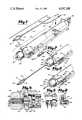
- FIG. 1is a pictorial view of the apparatus of the invention with some parts exploded;
- FIG. 2is a partial pictorial view of the apparatus with some parts of FIG. 1 assembled;
- FIG. 3is a partial pictorial view of the apparatus with parts of FIG. 1 further assembled;
- FIG. 4is a vertical sectional elevation taken along line 4--4 of FIG. 2 and slightly enlarged;
- FIG. 5is a partial plan view with parts cut away taken at 5 of FIG. 1, and
- FIG. 6is a vertical section with parts cut away, the section being taken along line 6--6 of FIG. 5 and slightly enlarged.
- FIG. 1there is shown in FIG. 1 the improved dispensing apparatus of this invention, the apparatus having its disposable dispensing probe disconnected from the dispensing housing 12.
- Probe or tubular member 10has a length sufficient to pass through the vaginal cavity and into the uterine cavity of a female primate.
- Member 10has a longitudinal passage extending throughout its length.
- a balloon assembly, indicated generally at 14is mounted on the upper or outer end of member 10.
- Balloon assembly 14has a flexible and expandable sleeve member 16 surrounding the upper end of probe 10.
- Fasteners 18 and 20, such as a collar or the like,provide the attachment of sleeve or sheath 16 to probe 10.
- Probe 10has a plurality of openings (not shown) which provide communication between the probe interior passage and a chamber within sleeve member 16.
- Sleeve member 16may be a tubular sheet member of soft and relaxed, flexible and elastic material, such as rubber or plastic, that expands with minimum tension.
- the material used for member 16has a low surface tension which allows uniform expansion under relatively low pressure.
- Member 16will thus expand to substantially fill a uterine cavity in which it is placed and conform to the shape of the cavity without applying extreme pressures to localized portions of the uterine walls. Through its extreme flexibility, member 16 will also expand into and conform to the shape of the isthmus at each Fallopian tube opening in the uterine cavity. This will substantially or effectively seal each isthmus.
- the upper or outer end of probe 10includes the terminal portion of an elongated tube 22 which is secured by a cyanoacrylic adhesive or the like to probe 10 at 24 and enters it to interiorly extend the length of probe 10.
- Tube 22is hollow and acts as a conduit for carrying a set-table fluid-like material to the upper or outer end of probe 10 which in turn directs the material into the upper section of a uterine cavity into which probe 10 has been inserted.
- Two conduitsare thereby provided in tube 10, a first conduit provided by probe 10 and a second conduit provided by tube 22 inside of probe 10.
- Tube 22terminates at its other end in a sharp needle-like end 42 and a support member 44 which carries needle 42.
- the open end of needle 42is covered and closed by means of a rubber or elastomer member 46.
- Probe 10is connected to housing 12 as shown in FIGS. 2 and 4 by means of an internally threaded female cap 26 which mates with an externally threaded male member 28 (seen in FIG. 4) extending from housing 12.
- Cap 26includes a central opening 30 through which probe 10 extends to seat in an O-ring assembly 32 by means of a mating annular depression 34 on the end of the probe which snaps into the O-ring. The parts may be tapered relative to each other so as to insure for tight fit.
- probe 10is enabled to function as a conduit for the supply and withdrawal of air to balloon assembly 14 through communication with the piston 36 and vented cylinder 38 assembly by means of conduit 40 within housing 12, details of which are shown in FIG. 4. Reference may be had to the aforementioned incorporated patents for additional detail.
- Cradle 48is shaped so as to provide a seat 50 for support member 44 and to allow needle 42 and sealing member 46 to extend rearwardly thereof.
- a locking arm 52is rotatably carried on male member 28 between cap 26 and the end of housing 12 so as to be clamped therebetween in various selected positions by tightening cap 26 as shown in FIGS. 1 and 3.
- a fixed stop 53may also be carried by housing 12. In FIG. 1 arm 52 is turned up and away from cradle 48. In FIG. 3, arm 52 is turned downwardly so as to rest against support member 44 to hold tube 22 and needle 42 in a fixed position in cradle 48.
- Housing 12is also adapted to include another cradle arrangement generally indicated at 54 which is shaped to receive a material or chemical container or ampule 56.
- Ampule 56as fully described in the aforenoted incorporated patents includes a tubular container body 58, an end 60 adapted to receive and be punctured by needle 42 and an opposite end 62 adapted to be acted upon by a push rod member 64 carried by housing 12 which pushes end 62 into body 58 to force the contents of the ampule into tube 22 and out the end of probe 10 into the uterine cavity.
- protective end member 46is allowed to remain impaled needle 42 when ampule 56 is placed in cradle 54. Member 46 is merely pushed further onto needle 42 as ampule end 60 is forced against needle 42 by action of push rod 64 during operation of the device. This arrangement allows needle 42 to penetrate ampule 56 with minimal compromise of the sterility of the needle and to maintain tube 22 in a closed condition during insertion of probe 10 into the uterus thereby preventing entrance of any vaginal or other body fluids into probe 10.
- a disposable probe 10 including tube 22 with protected sterile needle 42is provided which is completely external to housing 12 and easily connected thereto and easily disconnected therefrom.
- the devicealso includes a finger ring 66 which is connected to an elongated actuator assembly, generally indicated at 68 in FIG. 5, which is slidably received inside housing 12 as is fully described in the aforenoted and incorporated patents.
- the assemblyis connected to piston 36 and to push rod 66 so as to enable them to be moved reciprocably within cylinder 38 and cradle 54, respectively, by reciprocably manipulating finger ring 66.
- Such an arrangementis described in some of the aforenoted and incorporated patents as a single stroke actuator arrangement.
- the single stroke actuator assembly 68includes the following arrangement which is best seen in FIGS. 4, 5 and 6.
- cylinder 38includes an annular pressure release groove 70.
- a short cylinderical boss 72extends inwardly from the center of wall 74. The inner end of probe 10 connects to boss 72 where air passage 40 is provided.
- the actuator assembly 68also includes a piston 36 slidably carried in cylinder 38.
- Piston 36has a closed forward end or head which includes an open bore or recess 76 for accommodating boss 72 when piston 38 is in the full "in” position.
- the head of piston 36also includes a peripheral outwardly open notch portion indicated at 78 accommodating a sealing or O-ring seal 80.
- Notch 78 on piston 36is open to groove 70 and the piston includes a short radial vent passage (not shown) connecting base 76 to notch 78. Notch 78 and the radial vent passage thus provide an air passage between passage 40 and groove 70.
- actuator assembly 68has an elongated tubular body 82 slidably located within piston 38. As shown in FIGS. 5 and 6 a pair of ears 84 are connected to body 82 serving to interconnect it to push rod 64 whereby single action is obtained for movement of both piston 36 and push rod 64 by manipulation of finger ring 66. Movement of tubular body 12 inwardly carried the forward edges of ears 84 against shoulder 86 on push rod 64.
- Actuator assembly 68is movable with housing 12 to a first full “in” position close to the bottom of cylinder 38. In use, before an ampule has been placed in cradle 54, the actuator assembly is moved to the full "in” position by pushing finger ring 66 all the way into housing 12. This exposes push rod 64 placing it in cradle 54 as shown in FIG. 1 preventing the loading of an ampule into the apparatus. Any air trapped in sleeve 16 is vented or evacuated by means of the air passage formed between notch 78 and groove 70.
- the actuator assemblyis then retracted slightly from housing 12. This establishes a vacuum force on sleeve 16 collapsing it tightly against probe 10. The vacuum force is established because O-ring 80 moves out of groove 70 and into sealing engagement with the cylinder wall proper.
- the instrumentis now ready for insertion of probe 10 into the vagina and uterine cavities. To facilitate handling of the instrument during this phase of the procedure, it has been equipped with a normally unlatched button 88 which may be depressed to a latched or locked position as shown in FIG. 6.
- button 88is fitted with an upwardly biasing spring 90 which maintains it in its normal upward unlocked position.
- button 88may be depressed so as to cause its bottom portion to be interposed between ears 84 and shoulder 86 to hold the actuator assembly in position by holding button 88 down. This facilitates handling of the instrument during insertion into the body and prevents the vacuum at sleeve 16 from drawing the actuator assembly to the full "in” position and accidentially venting the sleeve.
- button 88is released and actuator assembly 68 is moved to its full "out” position by withdrawing finger ring 66.
- Piston 36is moved outwardly in cylinder 38 locating O-ring 80 outwardly of a small vent hole (not shown) in the cylinder. Air then flows into cylinder chamber 38 through the hole.
- Push rod 64is also retracted to a rearward position by this motion, clearing cradle 54 so that an ampule can be loaded therein.
- actuator assembly 68is pushed into housing 12. As it moves inwardly, sleeve 16 partially expands and ampule 56 is punctured causing the contents to be dispensed through tube 22 out of the end of probe 10 into the uterine cavity. Continued inward movement of the actuator assembly expands sleeve 16 further, pushing the dispensed materials into the Fallopian tubes.
- Sleeve 16is collapsed by partially withdrawing finger ring 66 from housing 12. This moves piston 36 outwardly to again form a vacuum which collapses the sleeve. Button 88 is pushed down and the instrument is removed from the body.
Landscapes
- Health & Medical Sciences (AREA)
- Reproductive Health (AREA)
- Engineering & Computer Science (AREA)
- Biomedical Technology (AREA)
- Heart & Thoracic Surgery (AREA)
- Vascular Medicine (AREA)
- Life Sciences & Earth Sciences (AREA)
- Animal Behavior & Ethology (AREA)
- General Health & Medical Sciences (AREA)
- Public Health (AREA)
- Veterinary Medicine (AREA)
- Surgical Instruments (AREA)
Abstract
Description
Claims (17)
Priority Applications (1)
| Application Number | Priority Date | Filing Date | Title |
|---|---|---|---|
| US06/551,058US4547188A (en) | 1983-11-14 | 1983-11-14 | Material dispensing apparatus |
Applications Claiming Priority (1)
| Application Number | Priority Date | Filing Date | Title |
|---|---|---|---|
| US06/551,058US4547188A (en) | 1983-11-14 | 1983-11-14 | Material dispensing apparatus |
Publications (1)
| Publication Number | Publication Date |
|---|---|
| US4547188Atrue US4547188A (en) | 1985-10-15 |
Family
ID=24199668
Family Applications (1)
| Application Number | Title | Priority Date | Filing Date |
|---|---|---|---|
| US06/551,058Expired - Fee RelatedUS4547188A (en) | 1983-11-14 | 1983-11-14 | Material dispensing apparatus |
Country Status (1)
| Country | Link |
|---|---|
| US (1) | US4547188A (en) |
Cited By (9)
| Publication number | Priority date | Publication date | Assignee | Title |
|---|---|---|---|---|
| US5904665A (en)* | 1995-03-07 | 1999-05-18 | Vance Products Inc. | Automated prolonged slow release intrauterine insemination using self retaining intrauterine insemination catheter |
| US6673008B1 (en) | 1998-04-28 | 2004-01-06 | Ronald J. Thompson | Fallopian tube and method of in vitro fertilization and embryo development |
| US8048101B2 (en) | 2004-02-25 | 2011-11-01 | Femasys Inc. | Methods and devices for conduit occlusion |
| US8048086B2 (en) | 2004-02-25 | 2011-11-01 | Femasys Inc. | Methods and devices for conduit occlusion |
| US8052669B2 (en) | 2004-02-25 | 2011-11-08 | Femasys Inc. | Methods and devices for delivery of compositions to conduits |
| US9238127B2 (en) | 2004-02-25 | 2016-01-19 | Femasys Inc. | Methods and devices for delivering to conduit |
| US9554826B2 (en) | 2008-10-03 | 2017-01-31 | Femasys, Inc. | Contrast agent injection system for sonographic imaging |
| US10070888B2 (en) | 2008-10-03 | 2018-09-11 | Femasys, Inc. | Methods and devices for sonographic imaging |
| US12171463B2 (en) | 2008-10-03 | 2024-12-24 | Femasys Inc. | Contrast agent generation and injection system for sonographic imaging |
Citations (2)
| Publication number | Priority date | Publication date | Assignee | Title |
|---|---|---|---|---|
| US4109654A (en)* | 1976-08-10 | 1978-08-29 | Population Research, Inc. | Single stroke dispensing apparatus |
| US4182328A (en)* | 1977-11-23 | 1980-01-08 | Population Research Incorporated | Dispensing instrument and method |
- 1983
- 1983-11-14USUS06/551,058patent/US4547188A/ennot_activeExpired - Fee Related
Patent Citations (2)
| Publication number | Priority date | Publication date | Assignee | Title |
|---|---|---|---|---|
| US4109654A (en)* | 1976-08-10 | 1978-08-29 | Population Research, Inc. | Single stroke dispensing apparatus |
| US4182328A (en)* | 1977-11-23 | 1980-01-08 | Population Research Incorporated | Dispensing instrument and method |
Cited By (29)
| Publication number | Priority date | Publication date | Assignee | Title |
|---|---|---|---|---|
| US5904665A (en)* | 1995-03-07 | 1999-05-18 | Vance Products Inc. | Automated prolonged slow release intrauterine insemination using self retaining intrauterine insemination catheter |
| US6673008B1 (en) | 1998-04-28 | 2004-01-06 | Ronald J. Thompson | Fallopian tube and method of in vitro fertilization and embryo development |
| US9308023B2 (en) | 2004-02-25 | 2016-04-12 | Femasys Inc. | Methods and devices for conduit occlusion |
| US9034053B2 (en) | 2004-02-25 | 2015-05-19 | Femasys Inc. | Methods and devices for conduit occlusion |
| US8052669B2 (en) | 2004-02-25 | 2011-11-08 | Femasys Inc. | Methods and devices for delivery of compositions to conduits |
| US8316854B2 (en) | 2004-02-25 | 2012-11-27 | Femasys Inc. | Methods and devices for conduit occlusion |
| US8316853B2 (en) | 2004-02-25 | 2012-11-27 | Femasys Inc. | Method and devices for conduit occlusion |
| US8324193B2 (en) | 2004-02-25 | 2012-12-04 | Femasys Inc. | Methods and devices for delivery of compositions to conduits |
| US8336552B2 (en) | 2004-02-25 | 2012-12-25 | Femasys Inc. | Methods and devices for conduit occlusion |
| US8695606B2 (en) | 2004-02-25 | 2014-04-15 | Femasys Inc. | Methods and devices for conduit occlusion |
| US8726906B2 (en) | 2004-02-25 | 2014-05-20 | Femasys Inc. | Methods and devices for conduit occlusion |
| US10292732B2 (en) | 2004-02-25 | 2019-05-21 | Femasys, Inc. | Methods and devices for conduit occlusion |
| US9220880B2 (en) | 2004-02-25 | 2015-12-29 | Femasys Inc. | Methods and devices for delivery of compositions to conduits |
| US9402762B2 (en) | 2004-02-25 | 2016-08-02 | Femasys Inc. | Methods and devices for conduit occlusion |
| US8048086B2 (en) | 2004-02-25 | 2011-11-01 | Femasys Inc. | Methods and devices for conduit occlusion |
| US8048101B2 (en) | 2004-02-25 | 2011-11-01 | Femasys Inc. | Methods and devices for conduit occlusion |
| US9238127B2 (en) | 2004-02-25 | 2016-01-19 | Femasys Inc. | Methods and devices for delivering to conduit |
| US9839444B2 (en) | 2004-02-25 | 2017-12-12 | Femasys Inc. | Methods and devices for conduit occlusion |
| US11779372B2 (en) | 2004-02-25 | 2023-10-10 | Femasys Inc. | Methods and devices for conduit occlusion |
| US10111687B2 (en) | 2004-02-25 | 2018-10-30 | Femasys, Inc. | Methods and devices for conduit occlusion |
| US11980395B2 (en) | 2008-10-03 | 2024-05-14 | Femasys Inc. | Methods and devices for sonographic imaging |
| US10258375B2 (en) | 2008-10-03 | 2019-04-16 | Femasys, Inc. | Methods and devices for sonographic imaging |
| US10172643B2 (en) | 2008-10-03 | 2019-01-08 | Femasys, Inc. | Contrast agent generation and injection system for sonographic imaging |
| US11154326B2 (en) | 2008-10-03 | 2021-10-26 | Femasys Inc. | Methods and devices for sonographic imaging |
| US11648033B2 (en) | 2008-10-03 | 2023-05-16 | Femasys Inc. | Methods and devices for sonographic imaging |
| US10070888B2 (en) | 2008-10-03 | 2018-09-11 | Femasys, Inc. | Methods and devices for sonographic imaging |
| US9554826B2 (en) | 2008-10-03 | 2017-01-31 | Femasys, Inc. | Contrast agent injection system for sonographic imaging |
| US12171463B2 (en) | 2008-10-03 | 2024-12-24 | Femasys Inc. | Contrast agent generation and injection system for sonographic imaging |
| US12426923B2 (en) | 2008-10-03 | 2025-09-30 | Femasys Inc. | Methods and devices for sonographic imaging |
Similar Documents
| Publication | Publication Date | Title |
|---|---|---|
| US4182328A (en) | Dispensing instrument and method | |
| EP0010650B1 (en) | Instrument for dispensing material into the fallopian tubes | |
| US4109654A (en) | Single stroke dispensing apparatus | |
| US3707146A (en) | Means to inject a plastic into a cavity to produce a replica thereof | |
| JP2617104B2 (en) | Injection device | |
| US7086431B2 (en) | Injection cartridge filling apparatus | |
| US4547188A (en) | Material dispensing apparatus | |
| US7549972B2 (en) | Tool for extracting vitreous samples from an eye | |
| USRE29207E (en) | Dispensing method and apparatus | |
| US3972331A (en) | Dispensing catheter | |
| US3656472A (en) | Instrument for the parenteral penetration of a needle | |
| US4126134A (en) | Dispensing instrument | |
| US6206857B1 (en) | Syringe with needle retraction arrangement | |
| CA1069791A (en) | Dispensing instrument and method | |
| US4248223A (en) | Self-priming parenteral administering apparatus | |
| US20090036840A1 (en) | Atraumatic ball tip and side wall opening | |
| US4119098A (en) | Material dispensing apparatus | |
| EP0812178A1 (en) | Kit for storage and mixing of agents of which at least one is liquid | |
| EA022529B1 (en) | DEVICE FOR INPUTS OF THE INTRA-CURRENT SYSTEM | |
| US4612924A (en) | Intrauterine contraceptive device | |
| EP0366292B1 (en) | Single channel balloon uterine injector | |
| US5807320A (en) | Bottle squeezing method | |
| US3887112A (en) | Apparatus for puncturing and collapsing a container | |
| US5399162A (en) | Automatic balling gun | |
| KR810000966Y1 (en) | Intrauterine medication |
Legal Events
| Date | Code | Title | Description |
|---|---|---|---|
| AS | Assignment | Owner name:BIONEXUS, INC., 5257 NORTH BOULEVARD, RALEIGH, NC Free format text:ASSIGNMENT OF ASSIGNORS INTEREST.;ASSIGNOR:BOLDUC, LEE R.;REEL/FRAME:004196/0151 Effective date:19831102 Owner name:BIONEXUS, INC., A CORP OF NC, NORTH CAROLINA Free format text:ASSIGNMENT OF ASSIGNORS INTEREST;ASSIGNOR:BOLDUC, LEE R.;REEL/FRAME:004196/0151 Effective date:19831102 | |
| AS | Assignment | Owner name:DUNCAN, CLAYTON I., 616 MILOWE ROAD, RALEIGH, NC Free format text:MORTGAGE;ASSIGNOR:BIONEXUS, INC., A MN CORP;REEL/FRAME:004608/0919 Effective date:19860925 Owner name:PIROTTE, JOHN K., 14240 WYNDFIELD CIRCLE, RALEIGH, Free format text:MORTGAGE;ASSIGNOR:BIONEXUS, INC., A MN CORP;REEL/FRAME:004608/0919 Effective date:19860925 Owner name:EDWARDS, LUCILLE L., ROUTE 10, BOX 245, CHAPEL HIL Free format text:MORTGAGE;ASSIGNOR:BIONEXUS, INC., A MN CORP;REEL/FRAME:004608/0919 Effective date:19860925 Owner name:WOODY, W. RUFFIN, JR., P.O. BOX 381, ROXBORO, NC Free format text:MORTGAGE;ASSIGNOR:BIONEXUS, INC., A MN CORP;REEL/FRAME:004608/0919 Effective date:19860925 | |
| AS | Assignment | Owner name:PDEW, INC., 4700 HOMEWOOD COURT, SUITE 340, RALEIG Free format text:ASSIGNMENT OF ASSIGNORS INTEREST.;ASSIGNORS:PIROTTE, JOHN, K.,;EDWARDS, LUCILLE L.;WOODY, W., RUFFIN, JR.,;AND OTHERS;REEL/FRAME:004828/0004;SIGNING DATES FROM 19870928 TO 19871216 Owner name:CRX MEDICAL, INC., 5265 NORTH BOULEVARD, RALEIGH, Free format text:ASSIGNMENT OF ASSIGNORS INTEREST.;ASSIGNORS:PIROTTE, JOHN, K.;EDWARDS, LUCILLE;WOODY, W., RUFFIN, JR.;AND OTHERS;REEL/FRAME:004831/0256;SIGNING DATES FROM 19870928 TO 19871210 Owner name:PDEW, INC., A CORP. OF NORTH CAROLINA,NORTH CARO Free format text:ASSIGNMENT OF ASSIGNORS INTEREST;ASSIGNORS:PIROTTE, JOHN, K.,;EDWARDS, LUCILLE L.;WOODY, W., RUFFIN, JR.,;AND OTHERS;SIGNING DATES FROM 19870928 TO 19871216;REEL/FRAME:004828/0004 Owner name:CRX MEDICAL, INC., NORTH A CORP. OF NC.,NEW YORK Free format text:ASSIGNMENT OF ASSIGNORS INTEREST;ASSIGNORS:PIROTTE, JOHN, K.;EDWARDS, LUCILLE;WOODY, W., RUFFIN, JR.;AND OTHERS;SIGNING DATES FROM 19870928 TO 19871210;REEL/FRAME:004831/0256 | |
| FEPP | Fee payment procedure | Free format text:PAYOR NUMBER ASSIGNED (ORIGINAL EVENT CODE: ASPN); ENTITY STATUS OF PATENT OWNER: SMALL ENTITY | |
| REMI | Maintenance fee reminder mailed | ||
| FPAY | Fee payment | Year of fee payment:4 | |
| SULP | Surcharge for late payment | ||
| FPAY | Fee payment | Year of fee payment:8 | |
| AS | Assignment | Owner name:FAMILY HEALTH INTERNATIONAL, NORTH CAROLINA Free format text:ASSIGNMENT OF ASSIGNORS INTEREST.;ASSIGNOR:PAHL, J. LARKIN, TRUSTEE IN THE MATTER OF BIONEXUS, INC., DEBTOR (CASE NO. 88-01115-S05 CHAPTER 7) NOW PENDING IN THE U.S. BANKRUPTCY COURT, EASTERN DISTRICT OF NORTH CAROLINA, RALEIGH;REEL/FRAME:006505/0051 Effective date:19930402 | |
| REMI | Maintenance fee reminder mailed | ||
| LAPS | Lapse for failure to pay maintenance fees | ||
| FP | Lapsed due to failure to pay maintenance fee | Effective date:19971015 | |
| STCH | Information on status: patent discontinuation | Free format text:PATENT EXPIRED DUE TO NONPAYMENT OF MAINTENANCE FEES UNDER 37 CFR 1.362 |