US4547027A - Modular swivel connector - Google Patents
Modular swivel connectorDownload PDFInfo
- Publication number
- US4547027A US4547027AUS06/582,101US58210184AUS4547027AUS 4547027 AUS4547027 AUS 4547027AUS 58210184 AUS58210184 AUS 58210184AUS 4547027 AUS4547027 AUS 4547027A
- Authority
- US
- United States
- Prior art keywords
- monitor module
- module
- teeth
- monitor
- stop means
- Prior art date
- Legal status (The legal status is an assumption and is not a legal conclusion. Google has not performed a legal analysis and makes no representation as to the accuracy of the status listed.)
- Expired - Fee Related
Links
Images


Classifications
- G—PHYSICS
- G06—COMPUTING OR CALCULATING; COUNTING
- G06F—ELECTRIC DIGITAL DATA PROCESSING
- G06F1/00—Details not covered by groups G06F3/00 - G06F13/00 and G06F21/00
- G06F1/16—Constructional details or arrangements
- G06F1/18—Packaging or power distribution
- G06F1/189—Power distribution
- F—MECHANICAL ENGINEERING; LIGHTING; HEATING; WEAPONS; BLASTING
- F16—ENGINEERING ELEMENTS AND UNITS; GENERAL MEASURES FOR PRODUCING AND MAINTAINING EFFECTIVE FUNCTIONING OF MACHINES OR INSTALLATIONS; THERMAL INSULATION IN GENERAL
- F16M—FRAMES, CASINGS OR BEDS OF ENGINES, MACHINES OR APPARATUS, NOT SPECIFIC TO ENGINES, MACHINES OR APPARATUS PROVIDED FOR ELSEWHERE; STANDS; SUPPORTS
- F16M11/00—Stands or trestles as supports for apparatus or articles placed thereon ; Stands for scientific apparatus such as gravitational force meters
- F16M11/02—Heads
- F16M11/04—Means for attachment of apparatus; Means allowing adjustment of the apparatus relatively to the stand
- F16M11/06—Means for attachment of apparatus; Means allowing adjustment of the apparatus relatively to the stand allowing pivoting
- F16M11/10—Means for attachment of apparatus; Means allowing adjustment of the apparatus relatively to the stand allowing pivoting around a horizontal axis
- F—MECHANICAL ENGINEERING; LIGHTING; HEATING; WEAPONS; BLASTING
- F16—ENGINEERING ELEMENTS AND UNITS; GENERAL MEASURES FOR PRODUCING AND MAINTAINING EFFECTIVE FUNCTIONING OF MACHINES OR INSTALLATIONS; THERMAL INSULATION IN GENERAL
- F16M—FRAMES, CASINGS OR BEDS OF ENGINES, MACHINES OR APPARATUS, NOT SPECIFIC TO ENGINES, MACHINES OR APPARATUS PROVIDED FOR ELSEWHERE; STANDS; SUPPORTS
- F16M11/00—Stands or trestles as supports for apparatus or articles placed thereon ; Stands for scientific apparatus such as gravitational force meters
- F16M11/20—Undercarriages with or without wheels
- F16M11/2007—Undercarriages with or without wheels comprising means allowing pivoting adjustment
- F16M11/2014—Undercarriages with or without wheels comprising means allowing pivoting adjustment around a vertical axis
- Y—GENERAL TAGGING OF NEW TECHNOLOGICAL DEVELOPMENTS; GENERAL TAGGING OF CROSS-SECTIONAL TECHNOLOGIES SPANNING OVER SEVERAL SECTIONS OF THE IPC; TECHNICAL SUBJECTS COVERED BY FORMER USPC CROSS-REFERENCE ART COLLECTIONS [XRACs] AND DIGESTS
- Y10—TECHNICAL SUBJECTS COVERED BY FORMER USPC
- Y10S—TECHNICAL SUBJECTS COVERED BY FORMER USPC CROSS-REFERENCE ART COLLECTIONS [XRACs] AND DIGESTS
- Y10S248/00—Supports
- Y10S248/917—Video display screen support
- Y10S248/919—Adjustably orientable video screen support
- Y10S248/921—Plural angular
Definitions
- the inventionrelates generally to mechanical and electrical connectors, and more particularly to a novel apparatus for effecting both the mechanical and the electrical connection of two modules which additionally allows the one module to be swiveled with respect to the other and which also permits the two modules to be readily electrically and mechanically connected and disconnected.
- Cathode ray tube (CRT) terminalsare becoming an ever increasingly popular means of communicating with computers and computerized data banks. Accordingly, in many computerized work environments, each individual work station is provided with its own CRT terminal.
- the monitor screen housing of a CRT type video computer terminalforms a monitor module; the base thereof housing the power supply and the electrical interface to other computer equipment forms a base module.
- the two modulesare mechanically and electrically connected to one another such that, in use, the monitor module may be supported by and swiveled with respect to the base module; furthermore, the two modules may be readily disconnected mechanically and electrically from one another when required for the purposes of maintenance.
- the base moduleis provided with a raised central plateau portion provided with first polarized electrical connecting means. Surrounding the central plateau portion is a circular locking ring having a plurality of horizontally projecting teeth.
- the monitor moduleis provided with a lower plate which includes a connector configuration generally complementary to that of the base plate, including second polarized electrical connecting means adapted to be connected to the corresponding means of the base module and a second locking ring having teeth projecting in the opposite direction to the locking ring teeth of the base module and adapted to be lockingly engageable therewith.
- the two modulesare provided with first and second stop means for limiting the swiveling of the monitor module with respect to its base module to a predetermined angular extent and the disposition of the horizontally projecting teeth about their corresponding locking rings is such that they at least partially overlap in the vertical plane during any of the permitted angular rotation therebetween.
- At least some portion of the teeth on the monitor moduleare normally disposed directly below some portion of the teeth of the base module so that the two sets of teeth do not interfere with one another but nevertheless overlap so that the monitor module may be swiveled about the base while preventing the monitor module to be separated from the base module during normal use.
- the first stop meansBy making the first stop means movable, for maintenance the monitor module may be further rotated to a mating position defined by a third stop means at which the two sets of teeth do not so overlap and, accordingly, the two modules may be mechanically separated from one another.
- At least one of the two polarized electrical connection meansis permitted to rotate with respect to its corresponding locking ring.
- a spring detent meansis preferably included so as to maintain the electrical connection means in a predetermined fixed position relative to the locking ring such that when the two modules are disconnected but oriented above one another with the two sets of teeth aligned in their mating position, the two electrical connection means are also aligned with their respective polarization means so that as the monitor module is lowered onto the base module the two electrical connection means matingly engage at the same time the two locking rings are brought into their operative position.
- FIG. 1is an exploded partially cutaway isometric view showing the normal orientation of the monitor module with respect to the base module and also indicating how the monitor module may be tilted and swiveled with respect to the base module about respective tilt and swivel axes;
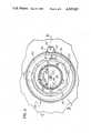
- FIG. 2is a top elevational view of the connector portion of the base module
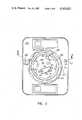
- FIG. 3is a bottom elevational view showing the connector portion of the monitor module and its associated tilt and swivel plate as seen from below;
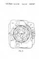
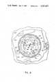
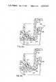
- FIG. 4is a plan view looking downwardly from above the tilt and swivel plate showing the two connectors coupled together when the monitor module is swiveled to its maximum clockwise extent as established by a first stop means;
- FIG. 5is generally similar to FIG. 4 but shows the monitor module rotated 180° counterclockwise from the position shown in FIG. 4 to the position established by a movable second stop means;
- FIG. 6is generally similar to FIGS. 4 and 5 but shows the monitor module rotated fully counterclockwise to the position established by a third fixed stop means whereat the two modules may be readily disconnected from each other;
- FIG. 7is a side cross-section view through the two halves of the connector assembly taken from the direction generally indicated by the arrows 7--7 in FIGS. 2 and 3;
- FIGS. 8a and FIG. 8bare detailed cross-sectional views showing how the horizontally projecting teeth provided as part of the upper and lower connector subassemblies may be rotated to respective unlocked and locked positions.
- FIG. 1shows a presently preferred embodiment of the present invention in use with a monitor module 10 removably and swivelably mounted to a base module 12.
- the letter Zrefers to the vertical axis about which the monitor module 10 swivels with respect to the base module 12 and the letter W designates the monitor's horizontal tilt axis.
- the base module 12is provided with a lower connector subassembly 14 of generally circular configuration including a raised central plateau 16 supporting a multi-circuit electrical connector 18 and also a lower locking ring 20 provided with a plurality of outwardly facing horizontal teeth 22 each radially oriented with respect to the vertical axis Z. Also visible in FIG. 1 is a fixed stop 24 and a displacable stop 26 as well as a lower annular load bearing surface 28.
- the monitor module 10comprises an outer cover housing 30 and a lower tilt and swivel plate 32 connected thereto by means of axle pins 34 oriented along the monitor's tilt axis W.
- suitable friction and/or spring means(not shown in the Figures) to maintain the desired tilted orientation of the outer cover 30 relative to the tilt and swivel plate 32, even with a relatively front-heavy cathode ray tube (not shown in the Figures) mounted inside the cover housing 30.
- the monitor module's tilt and swivel plate 32is provided with an upwardly extending connector recess 36 oriented about the vertical axis Z and dimensioned so as to accept the upwardly extending connector plateau 16 of the base module 12.
- a circular metal disk 38Rotatably secured to the plate's upwardly extending recess portion 36 is a circular metal disk 38 to which is attached a connector assembly 40 of a type that will matingly engage (and make respective electrical contacts to the corresponding circuits carried by) the lower electrical connector 18.
- the lower connector subassembly 14is also provided with a pair of relatively rigid upwardly extending locating lugs 42 which engage correspondingly apertured bosses 44 attached to the rotating disk 38, as well as a ground plug 46 which makes grounding contact to the aforesaid rotating disk 38 (and any components inside the monitor housing electrically connected thereto) via a ground socket 48.
- FIG. 2is an enlarged plan view of the connector subassembly portion 14 of the base module 12 as seen from above.
- the lock ring 20comprises a total of 10 outwardly projecting teeth 22 of varying angular extent.
- the displaceable stop 26is supported by a flexible finger 50 that extends outwardly from the connector subassembly 14 and bears an index marking 52 in the shape of an inwardly oriented triangle.
- the inner edge 54 of the flexible finger 50is hingedly attached to the base module 12.
- the displaceable stop 26is lowered to the level of an annular trough 56 (see also FIG. 7, the lower portion of which being a cross section through the connector subassembly of FIG. 2 as indicated by the arrow 7--7).
- FIG. 3is a plan elevational view of the tilt and swivel plate 32 (which is normally attached to the monitor housing 30 by means of axles 34 as shown in FIG. 1) as seen from below. From FIG. 3 it will be seen that the recessed area 36 which accommodates the raised plateau area 16 of the lower connector subassembly 14 is surrounded at its lower end by a circular locking ring 58 comprising 10 inwardly directed teeth 60 (see also the upper portion of FIG. 7). Comparing FIGS.
- the spacing and angular extent of the teeth 60 of the upper lock ring 58are complementary to the corresponding spacing and angular extent of the teeth 22 of the lower lock ring 20, such that the two sets of teeth will not interfere with one another only at one particular orientation of the upper lock ring 58 relative to the lower lock ring at 20, namely, when the index mark 52 associated with the lower connector subassembly 14 is radially aligned with a corresponding outwardly directed index triangle 62 provided on the upper surface of the tilt and swivel plate 32 (see also FIG. 6).
- FIG. 3Also visible in FIG. 3 are a pair of inner fixed stops 64, 66 which coact with the fixed stop 24 of the lower connector subassembly (see FIGS. 1 and 2) to limit the maximum rotation of the tilt and swivel plate 32 relative to the base module 12 to approximately 195°. Also visible in FIG. 3 are an outer pair of downwardly projecting fixed stops 68, 70 which coact with the upwardly directed displaceable stop 26 of the lower connector subassembly 14 to limit the normal swivel range of the monitor module 12 relative to the base module 10 to only 180°.
- FIGS. 4, 5 and 6respectively show the orientation of the tilt and swivel plate 32 relative to the connector portion 14 of the base module 12 when the monitor module is: (FIG. 4) swiveled to its maximum clockwise extent, (FIG. 5) rotated 180° counterclockwise therefrom (its normal maximum counterclockwise extent), and (FIG. 6) rotated to its fully counterclockwise position whereat the two modules may be readily disconnected from each other.
- FIGS. 4, 5 and 6respectively show the orientation of the tilt and swivel plate 32 relative to the connector portion 14 of the base module 12 when the monitor module is: (FIG. 4) swiveled to its maximum clockwise extent, (FIG. 5) rotated 180° counterclockwise therefrom (its normal maximum counterclockwise extent), and (FIG. 6) rotated to its fully counterclockwise position whereat the two modules may be readily disconnected from each other.
- FIGS. 4, 5 and 6are plan views looking downwardly from above the tilt and swivel plate.
- FIG. 3shows the tilt and swivel plate 32 as seen from below. Moreover, both the outwardly directed teeth 22 of the base connector subassembly 14 and the inwardly directed teeth 60 of the tilt and swivel plate 32 are shown in dashed outline since both sets of teeth are below the upper surface of the tilt and swivel plate 32. To further aid in the understanding of FIGS. 4, 5 and 6, the portion of the outwardly facing teeth 22 that actually overlaps the inwardly facing teeth 60 is indicated by light crosshatching and the base module's teeth 22 and their associated lock ring 20 are shown in lighter dashed outline, while the swivel plates teeth 60 and their respective locking ring 58 are shown in heavier dashed outline.
- the rotatable disk 38is held in place inside the upwardly extending recess 36 by means of three flexible fingers 72 integrally molded inside recess 36, as well as by a fixed protrusion 74 and an elongated flexible finger 76.
- three flexible fingers 72integrally molded inside recess 36, as well as by a fixed protrusion 74 and an elongated flexible finger 76.
- one edge thereofis placed under the fixed finger 74 and the elongated flexible finger 76 as the opposite edge is eased in position over the three short flexible fingers 72, thus temporarily deflecting the three short fingers into an outward retracted position until the disk 38 is resting against the inner annular surface 78 (FIG. 7) of the recess 36 and the three short flexible fingers 72 have thus snapped back to their normal position shown in the Figures.
- the elongated flexible finger 76is provided with an inwardly facing concave surface 80 and is thereby adapted to engage a circular locating boss 82 fixedly mounted to the disk 38 at a predetermined point adjacent its periphery.
- the rotatable disk 38may be retained in a predetermined angular position relative to the tilt and swivel plate 32.
- This predetermined positionis such that the upper connector assembly 40 is aligned with the lower connector assembly 18 fixedly positioned relative to the base of module 12 when the alignment arrow 62 molded on the upper surface of the tilt and swivel plate 32 is aligned with the corresponding index mark 52 integrally molded on the flexible finger 50 provided as part of the upper surface of the base module 12.
- FIGS. 3 and 6both show the rotatable plate 38 in the aforedescribed predetermined position relative to the swivel plate 32 with FIG. 3 showing the assembly from below and FIG. 6 showing it from above.
- FIGS. 4 and 5show the rotating plate 38 rotated from said predetermined position with FIG.
- FIG. 4shows the tilt and swivel plate rotated to its maximum permitted clockwise extent with the first fixed inner stop 64 of the tilt and swivel plate in contact with the fixed first stop 24 on the base module 12 and with the downwardly projecting first fixed outer stop 68 of the tilt and swivel plate in contact with the movable second stop 28 on the base (which collectively function as a first stop means).
- FIG. 5shows the tilt and swivel plate 32 rotated to the full counterclockwise extent of its normal travel with the downwardly protruding second fixed outer stop 70 in contact with the upwardly extending movable second stop 76 (which collectively function as a second stop means). Comparing FIGS.
- the tilt and swivel plate 32(and therefore the monitor housing 10 attached thereto) can be rotated approximately 180° relative to the base module 12. As shown in FIG. 6, a further 15° of counterclockwise movement is possible, when flexible finger 50 is depressed to permit the downwardly protruding second outer stop 70 to pass over the movable second stop 26 on the base module 12. Movement beyond this further 15° is prevented by the second fixed inner stop 66 of the tilt and swivel plate 32, as the latter makes contact with the fixed first stop 24 on the base module, as shown in dashed outline in FIG. 6. It will therefore be seen that the latter two stops (24 and 66) collectively function as a third stop means. It will also be seen that in this position the second outer stop 70 of the tilt and swivel plate 32 remains above the movable second stop 26 on the base module 12 and the respective alignment indicators 62 and 52 are pointing to each other.
- the upwardly extending recess 36 molded into the central portion of the tilt and swivel plate 32has an inner diameter only slightly larger than that of the outer diameter of the plateau portion 16 standing upwardly from the central portion of the base 12, and that the lowermost vertical extent of the recess portion 36 is terminated by a surrounding lower annular surface 84 which normally rests against the recessed annular bearing surface 28 of the lower connector subassembly 14.
- the raised plateau portion of the base module 12comprises a generally horizontally extending circular platform 86 which is secured at approximately the midpoint of a vertically extending cylindrical ring 88 that is integrally molded with the base 12 and which in turn comprises a plurality of flexible locking fingers 90 that cooperate with a molded annular ledge 92 to hold the plate 86 in position, the plate being secured against rotation by means of an inwardly projecting tab 94 which cooperates with a suitably shaped notch (not visible in the figures) provided at the periphery of the disk 86.
- the lower electrical connector subassembly 18is mounted on the lower surface plate 86 with the dimensions of the various elements being such that it is entirely below the upper edge of the vertical ring 88.
- the upper contact subassembly 40although extending downwardly from the rotatable disk 38, has a vertical dimension relative to that of the cylindrical recess 36 that its lowermost extent is well above the lower supporting annular surface 84.
- the plateau portion 16 of the base 12 and the recess 36 of the tilt and swivel plate 32cooperate to coarsely align the two modules as the monitor is being lowered onto the base, but they also serve to protect their respective electrical connector subassemblies 18 and 40 from the possibility of bent connector pins and other undesired consequences of improper alignment during the installation of the monitor module onto the base module or in the event that the monitor module is being temporarily set down on a surface not specifically designed to hold the monitor module, such as the flat surface of a workbench.
- the two alignment pins 42protrude sufficiently above the remainder of the plateau 16 that they serve as a second alignment means between the base module and the monitor module to effect a more precise alignment than that which would result upon reliance only on the shape of the plateau and the recess.
- the pins 42also serve to ensure that the plate 38 is in the proper angular orientation with respect to the vertical axis Z, and when the two modules have been assembled to one another, they also carry most of the torque resulting from the swiveling of the one module with respect to the other which otherwise would have to be transmitted by the electrical connector itself.
- the electrical circuit carrying pins 96 contained in the upper electrical connector assembly 40are contained within a protective recess 98 which is just slightly larger than the corresponding exposed portion 100 of the lower connector assembly 18. Such an arrangement further protects against the deleterious effects of any misalignment of the two connector subassemblies during the installation of the monitor module onto the base module.
- FIG. 8is an enlarged cross sectional view of the upper and lower locking rings 20 and 58
- the outwardly extending teeth 22 on the lower locking ring 20have a maximum diameter slightly less than the inner diameter of the upper locking ring 58 of those portions of the inner diameter of the upper locking ring 58 not provided with teeth (see FIG. 8a).
Landscapes
- Engineering & Computer Science (AREA)
- General Engineering & Computer Science (AREA)
- Power Engineering (AREA)
- Theoretical Computer Science (AREA)
- Mechanical Engineering (AREA)
- Human Computer Interaction (AREA)
- Physics & Mathematics (AREA)
- General Physics & Mathematics (AREA)
- Details Of Connecting Devices For Male And Female Coupling (AREA)
- Connector Housings Or Holding Contact Members (AREA)
- Devices For Indicating Variable Information By Combining Individual Elements (AREA)
Abstract
Description
Claims (9)
Priority Applications (4)
| Application Number | Priority Date | Filing Date | Title |
|---|---|---|---|
| US06/582,101US4547027A (en) | 1984-02-21 | 1984-02-21 | Modular swivel connector |
| DE19853505606DE3505606A1 (en) | 1984-02-21 | 1985-02-19 | SCREEN DEVICE WITH ROTATING MONITOR |
| GB08504340AGB2155287A (en) | 1984-02-21 | 1985-02-20 | Swivel connector |
| ES540583AES8606960A1 (en) | 1984-02-21 | 1985-02-21 | Modular swivel connector |
Applications Claiming Priority (1)
| Application Number | Priority Date | Filing Date | Title |
|---|---|---|---|
| US06/582,101US4547027A (en) | 1984-02-21 | 1984-02-21 | Modular swivel connector |
Publications (1)
| Publication Number | Publication Date |
|---|---|
| US4547027Atrue US4547027A (en) | 1985-10-15 |
Family
ID=24327848
Family Applications (1)
| Application Number | Title | Priority Date | Filing Date |
|---|---|---|---|
| US06/582,101Expired - Fee RelatedUS4547027A (en) | 1984-02-21 | 1984-02-21 | Modular swivel connector |
Country Status (4)
| Country | Link |
|---|---|
| US (1) | US4547027A (en) |
| DE (1) | DE3505606A1 (en) |
| ES (1) | ES8606960A1 (en) |
| GB (1) | GB2155287A (en) |
Cited By (56)
| Publication number | Priority date | Publication date | Assignee | Title |
|---|---|---|---|---|
| US4589713A (en)* | 1984-04-09 | 1986-05-20 | Raytheon Company | Video display support joint |
| US4645153A (en)* | 1985-05-23 | 1987-02-24 | Ncr Corporation | Tilt and swivel support |
| US4731030A (en)* | 1987-01-09 | 1988-03-15 | Unisys Corporation | Tilt and swivel assembly for terminal monitor |
| US4783036A (en)* | 1987-04-16 | 1988-11-08 | Anthro Corporation | Adjustable support |
| US4796842A (en)* | 1986-03-05 | 1989-01-10 | Mitsubishi Denki Kabushiki Kaisha | Swivel support structure for an electric apparatus |
| US4836486A (en)* | 1987-04-16 | 1989-06-06 | Anthro Corporation | Adjustable support |
| US5204667A (en)* | 1989-01-27 | 1993-04-20 | Yazaki Corporation | Indication display unit for vehicles |
| US5243434A (en)* | 1990-06-29 | 1993-09-07 | Mitsubishi Denki Kabushiki Kaisha | Swivel device for a television receiver |
| US5250851A (en)* | 1991-06-19 | 1993-10-05 | Proxima Corporation | Video monitor support and power distribution assembly |
| US5263678A (en)* | 1990-04-23 | 1993-11-23 | Norbac Corporation | Apparatus for periodically displacing a display terminal |
| US5445528A (en)* | 1994-05-31 | 1995-08-29 | The Whitaker Corporation | Electrical connector with improved mounting |
| USD363276S (en) | 1992-11-13 | 1995-10-17 | International Business Machines Corporation | Docking base for a portable computer |
| US5470041A (en)* | 1994-02-02 | 1995-11-28 | Cucinotta; James L. | Workstation for laptop-type computer |
| US5542850A (en)* | 1994-06-30 | 1996-08-06 | The Whitaker Corporation | Pivotal electrical connector |
| US5658152A (en)* | 1995-06-07 | 1997-08-19 | International Business Machines Corporation | Three prong swivel plug |
| US5749556A (en)* | 1993-12-28 | 1998-05-12 | Mitsubishi Denki Kabushiki Kaisha | Rotating apparatus |
| US5941618A (en)* | 1997-03-11 | 1999-08-24 | Mustek Corporation | Integrated point-of-sale cabinet system with removable covers |
| US5941493A (en)* | 1996-11-16 | 1999-08-24 | Adi Corporation | LCD support system |
| US6010111A (en)* | 1996-11-15 | 2000-01-04 | Samsung Electronics Co., Ltd. | Swiveling device for liquid crystal display monitor |
| US6032918A (en)* | 1996-11-03 | 2000-03-07 | Samsung Electronics Co., Ltd. | Multi-functional device for a display device |
| DE20012156U1 (en) | 2000-07-13 | 2000-11-23 | Loewe Opta GmbH, 96317 Kronach | Image display device |
| US6231020B1 (en) | 1997-11-19 | 2001-05-15 | James H. T. Willson | Swivel device for cable connected electronic components |
| US6268998B1 (en) | 1996-09-02 | 2001-07-31 | Samsung Electronics Co., Ltd. | Liquid crystal display monitor |
| US6275375B1 (en)* | 1997-01-10 | 2001-08-14 | Samsung Electronics Co., Ltd. | Monitor stand with hub mount |
| US20010017761A1 (en)* | 1993-06-29 | 2001-08-30 | Ditzik Richard J. | Desktop device with adjustable flat panel screen |
| US6346000B1 (en)* | 2001-05-02 | 2002-02-12 | Tom Orr | Apparatus for interlocking stacked computer modules |
| US6354550B2 (en)* | 1998-12-08 | 2002-03-12 | Lg Electronics Inc. | Method for controlling screen direction of a video display stand |
| US6370020B1 (en)* | 1999-05-06 | 2002-04-09 | Nec Corporation | Display apparatus with rotation mechanism |
| US6587333B2 (en)* | 2001-02-09 | 2003-07-01 | Acer Inc. | Flat panel display apparatus and tilt/swivel mechanism therein |
| US6595481B1 (en)* | 2002-02-01 | 2003-07-22 | Hannstar Display Corp. | Liquid crystal display and its rotary assembly |
| GB2361799B (en)* | 1998-12-23 | 2003-07-23 | Jerry Moscovitch | Computer display screen system and adustable screen mount and swinging screens therefor |
| US20030184193A1 (en)* | 2002-03-26 | 2003-10-02 | Samsung Electronics Co., Ltd. | Monitor having improved swiveling |
| US20040033704A1 (en)* | 2002-08-15 | 2004-02-19 | Basilio Selli | Rotatable assemblies and methods of securing such assemblies |
| US20040083577A1 (en)* | 2002-11-06 | 2004-05-06 | Lu Sheng-Nan | Hinge for a notebook computer |
| US20050146845A1 (en)* | 1998-11-20 | 2005-07-07 | Jerry Moscovitch | Computer display screen system and adjustable screen mount, and swinging screens therefor |
| US20060108705A1 (en)* | 2004-11-23 | 2006-05-25 | Rowley William W | Method for injection molding component fittings on extrudates |
| US20060181637A1 (en)* | 2005-02-16 | 2006-08-17 | Innovative Office Products, Inc. | Quick release assembly for an electronic device |
| US20070285881A1 (en)* | 2006-06-07 | 2007-12-13 | Kabushiki Kaisha Toshiba | Electronic device with rotatable display panel |
| US7380759B1 (en)* | 1998-11-16 | 2008-06-03 | Garmin Corporation | Multi-position articulating mounting apparatus for an electronic device |
| US7390211B2 (en) | 1999-08-23 | 2008-06-24 | Jerry Moscovitch | Universal quick connector apparatus for an LCD monitor |
| DE112004002340B4 (en)* | 2003-12-30 | 2009-10-01 | Ati Industrial Automation, Inc. | Electrical multi-position connector for a tool changer of a robot |
| US20090310293A1 (en)* | 2008-06-12 | 2009-12-17 | Datavan International Corp. | Quick-detachable mounting system |
| US20120012208A1 (en)* | 2010-07-15 | 2012-01-19 | Preston Industries, Inc. | Movable constant temperature circulator assembly |
| US20120273630A1 (en)* | 2010-10-15 | 2012-11-01 | Jon Simon Gillespie-Brown | Multimedia device stand |
| US20130027856A1 (en)* | 2011-07-27 | 2013-01-31 | Tzu-Wei Tai | Electronic apparatus with rotation function |
| US9293916B2 (en) | 2009-07-15 | 2016-03-22 | Yehuda Binder | Sequentially operated modules |
| US9419378B2 (en) | 2011-08-26 | 2016-08-16 | Littlebits Electronics Inc. | Modular electronic building systems with magnetic interconnections and methods of using the same |
| US9597607B2 (en) | 2011-08-26 | 2017-03-21 | Littlebits Electronics Inc. | Modular electronic building systems with magnetic interconnections and methods of using the same |
| US9696754B2 (en) | 2014-03-26 | 2017-07-04 | Intel Corporation | Hinge having multiple degrees of freedom |
| US9829148B2 (en)* | 2015-10-03 | 2017-11-28 | Samuel Choquette | Rotatable platter for a monitor having a passage for wiring and a stopper |
| US9845912B2 (en) | 2015-09-30 | 2017-12-19 | Invue Security Products Inc. | Gang charger, shroud, and dock for portable electronic devices |
| US10155153B2 (en) | 2009-08-06 | 2018-12-18 | Littlebits Electronics, Inc. | Puzzle with conductive path |
| US10176345B2 (en) | 2012-10-31 | 2019-01-08 | Invue Security Products Inc. | Display stand for a tablet computer |
| US11330714B2 (en) | 2011-08-26 | 2022-05-10 | Sphero, Inc. | Modular electronic building systems with magnetic interconnections and methods of using the same |
| US11616844B2 (en) | 2019-03-14 | 2023-03-28 | Sphero, Inc. | Modular electronic and digital building systems and methods of using the same |
| US12267971B2 (en)* | 2022-10-17 | 2025-04-01 | Dell Products L.P. | Self-aligning and self-orientating swivel lock mechanism for desktop monitors |
Families Citing this family (5)
| Publication number | Priority date | Publication date | Assignee | Title |
|---|---|---|---|---|
| AU594385B2 (en)* | 1986-03-20 | 1990-03-08 | Wang Laboratories, Inc. | Display attachment apparatus |
| JPH0344720A (en)* | 1989-07-07 | 1991-02-26 | Internatl Business Mach Corp <Ibm> | Display terminal device |
| JPH078032B2 (en)* | 1990-06-29 | 1995-01-30 | 三菱電機株式会社 | Rotating device for television receiver |
| US5271590A (en)* | 1992-01-31 | 1993-12-21 | Rosen John B | Articulable projecting plug |
| DE9418390U1 (en)* | 1994-11-17 | 1995-02-02 | Hans-Joachim Bernstein Compact-Gehäuse GmbH, 32479 Hille | Swivel device |
Citations (1)
| Publication number | Priority date | Publication date | Assignee | Title |
|---|---|---|---|---|
| US3462112A (en)* | 1967-08-04 | 1969-08-19 | Warwick Electronics Inc | Connector assembly for pivotally mounted display tube |
Family Cites Families (2)
| Publication number | Priority date | Publication date | Assignee | Title |
|---|---|---|---|---|
| DE2414021C3 (en)* | 1974-03-22 | 1978-05-11 | Standard Elektrik Lorenz Ag, 7000 Stuttgart | Hinge for a detachable mechanical connection between two electrical devices |
| DE3036852C2 (en)* | 1980-09-30 | 1984-02-23 | Tandberg Data A/S, Oslo | Device for setting up a data display device on a work surface |
- 1984
- 1984-02-21USUS06/582,101patent/US4547027A/ennot_activeExpired - Fee Related
- 1985
- 1985-02-19DEDE19853505606patent/DE3505606A1/ennot_activeWithdrawn
- 1985-02-20GBGB08504340Apatent/GB2155287A/ennot_activeWithdrawn
- 1985-02-21ESES540583Apatent/ES8606960A1/ennot_activeExpired
Patent Citations (1)
| Publication number | Priority date | Publication date | Assignee | Title |
|---|---|---|---|---|
| US3462112A (en)* | 1967-08-04 | 1969-08-19 | Warwick Electronics Inc | Connector assembly for pivotally mounted display tube |
Cited By (96)
| Publication number | Priority date | Publication date | Assignee | Title |
|---|---|---|---|---|
| US4589713A (en)* | 1984-04-09 | 1986-05-20 | Raytheon Company | Video display support joint |
| US4645153A (en)* | 1985-05-23 | 1987-02-24 | Ncr Corporation | Tilt and swivel support |
| US4796842A (en)* | 1986-03-05 | 1989-01-10 | Mitsubishi Denki Kabushiki Kaisha | Swivel support structure for an electric apparatus |
| US4731030A (en)* | 1987-01-09 | 1988-03-15 | Unisys Corporation | Tilt and swivel assembly for terminal monitor |
| US4783036A (en)* | 1987-04-16 | 1988-11-08 | Anthro Corporation | Adjustable support |
| US4836486A (en)* | 1987-04-16 | 1989-06-06 | Anthro Corporation | Adjustable support |
| US5204667A (en)* | 1989-01-27 | 1993-04-20 | Yazaki Corporation | Indication display unit for vehicles |
| US5263678A (en)* | 1990-04-23 | 1993-11-23 | Norbac Corporation | Apparatus for periodically displacing a display terminal |
| US5243434A (en)* | 1990-06-29 | 1993-09-07 | Mitsubishi Denki Kabushiki Kaisha | Swivel device for a television receiver |
| US5250851A (en)* | 1991-06-19 | 1993-10-05 | Proxima Corporation | Video monitor support and power distribution assembly |
| USD363276S (en) | 1992-11-13 | 1995-10-17 | International Business Machines Corporation | Docking base for a portable computer |
| US20010017761A1 (en)* | 1993-06-29 | 2001-08-30 | Ditzik Richard J. | Desktop device with adjustable flat panel screen |
| US20060187626A1 (en)* | 1993-06-29 | 2006-08-24 | Ditzik Richard J | Desktop device with adjustable flat screen display |
| US7091961B2 (en) | 1993-06-29 | 2006-08-15 | Ditzik Richard J | Desktop device with adjustable flat screen display |
| US5749556A (en)* | 1993-12-28 | 1998-05-12 | Mitsubishi Denki Kabushiki Kaisha | Rotating apparatus |
| US5470041A (en)* | 1994-02-02 | 1995-11-28 | Cucinotta; James L. | Workstation for laptop-type computer |
| US5445528A (en)* | 1994-05-31 | 1995-08-29 | The Whitaker Corporation | Electrical connector with improved mounting |
| US5542850A (en)* | 1994-06-30 | 1996-08-06 | The Whitaker Corporation | Pivotal electrical connector |
| US5658152A (en)* | 1995-06-07 | 1997-08-19 | International Business Machines Corporation | Three prong swivel plug |
| US6268998B1 (en) | 1996-09-02 | 2001-07-31 | Samsung Electronics Co., Ltd. | Liquid crystal display monitor |
| US6032918A (en)* | 1996-11-03 | 2000-03-07 | Samsung Electronics Co., Ltd. | Multi-functional device for a display device |
| US6010111A (en)* | 1996-11-15 | 2000-01-04 | Samsung Electronics Co., Ltd. | Swiveling device for liquid crystal display monitor |
| US5941493A (en)* | 1996-11-16 | 1999-08-24 | Adi Corporation | LCD support system |
| US6275375B1 (en)* | 1997-01-10 | 2001-08-14 | Samsung Electronics Co., Ltd. | Monitor stand with hub mount |
| US5941618A (en)* | 1997-03-11 | 1999-08-24 | Mustek Corporation | Integrated point-of-sale cabinet system with removable covers |
| US6231020B1 (en) | 1997-11-19 | 2001-05-15 | James H. T. Willson | Swivel device for cable connected electronic components |
| US7380759B1 (en)* | 1998-11-16 | 2008-06-03 | Garmin Corporation | Multi-position articulating mounting apparatus for an electronic device |
| US20050146845A1 (en)* | 1998-11-20 | 2005-07-07 | Jerry Moscovitch | Computer display screen system and adjustable screen mount, and swinging screens therefor |
| USRE42091E1 (en) | 1998-11-20 | 2011-02-01 | Jerry Moscovitch | Computer display screen system and adjustable screen mount, and swinging screens therefor |
| US6354550B2 (en)* | 1998-12-08 | 2002-03-12 | Lg Electronics Inc. | Method for controlling screen direction of a video display stand |
| GB2361799B (en)* | 1998-12-23 | 2003-07-23 | Jerry Moscovitch | Computer display screen system and adustable screen mount and swinging screens therefor |
| US8462103B1 (en) | 1998-12-23 | 2013-06-11 | Jerry Moscovitch | Computer display screen system and adjustable screen mount, and swinging screens therefor |
| US6370020B1 (en)* | 1999-05-06 | 2002-04-09 | Nec Corporation | Display apparatus with rotation mechanism |
| US7390211B2 (en) | 1999-08-23 | 2008-06-24 | Jerry Moscovitch | Universal quick connector apparatus for an LCD monitor |
| DE20012156U1 (en) | 2000-07-13 | 2000-11-23 | Loewe Opta GmbH, 96317 Kronach | Image display device |
| US6587333B2 (en)* | 2001-02-09 | 2003-07-01 | Acer Inc. | Flat panel display apparatus and tilt/swivel mechanism therein |
| US6346000B1 (en)* | 2001-05-02 | 2002-02-12 | Tom Orr | Apparatus for interlocking stacked computer modules |
| US6595481B1 (en)* | 2002-02-01 | 2003-07-22 | Hannstar Display Corp. | Liquid crystal display and its rotary assembly |
| US20030184193A1 (en)* | 2002-03-26 | 2003-10-02 | Samsung Electronics Co., Ltd. | Monitor having improved swiveling |
| US20040033704A1 (en)* | 2002-08-15 | 2004-02-19 | Basilio Selli | Rotatable assemblies and methods of securing such assemblies |
| US7063537B2 (en) | 2002-08-15 | 2006-06-20 | Smar Research Corporation | Rotatable assemblies and methods of securing such assemblies |
| US20040083577A1 (en)* | 2002-11-06 | 2004-05-06 | Lu Sheng-Nan | Hinge for a notebook computer |
| US6742221B2 (en)* | 2002-11-06 | 2004-06-01 | Shin Zu Shing Co., Ltd. | Hinge for a notebook computer |
| DE112004002340B4 (en)* | 2003-12-30 | 2009-10-01 | Ati Industrial Automation, Inc. | Electrical multi-position connector for a tool changer of a robot |
| US20060108705A1 (en)* | 2004-11-23 | 2006-05-25 | Rowley William W | Method for injection molding component fittings on extrudates |
| US7673838B2 (en) | 2005-02-16 | 2010-03-09 | Innovative Office Products, Inc. | Quick release assembly for an electronic device |
| US20060181637A1 (en)* | 2005-02-16 | 2006-08-17 | Innovative Office Products, Inc. | Quick release assembly for an electronic device |
| US7551431B2 (en)* | 2006-06-07 | 2009-06-23 | Kabushiki Kaisha Toshiba | Electronic device with rotatable display panel |
| US20070285881A1 (en)* | 2006-06-07 | 2007-12-13 | Kabushiki Kaisha Toshiba | Electronic device with rotatable display panel |
| US20090310293A1 (en)* | 2008-06-12 | 2009-12-17 | Datavan International Corp. | Quick-detachable mounting system |
| US10230237B2 (en) | 2009-07-15 | 2019-03-12 | Yehuda Binder | Sequentially operated modules |
| US9673623B2 (en) | 2009-07-15 | 2017-06-06 | Yehuda Binder | Sequentially operated modules |
| US10617964B2 (en) | 2009-07-15 | 2020-04-14 | May Patents Ltd. | Sequentially operated modules |
| US10589183B2 (en) | 2009-07-15 | 2020-03-17 | May Patents Ltd. | Sequentially operated modules |
| US9293916B2 (en) | 2009-07-15 | 2016-03-22 | Yehuda Binder | Sequentially operated modules |
| US10355476B2 (en) | 2009-07-15 | 2019-07-16 | Yehuda Binder | Sequentially operated modules |
| US9559519B2 (en) | 2009-07-15 | 2017-01-31 | Yehuda Binder | Sequentially operated modules |
| US9583940B2 (en) | 2009-07-15 | 2017-02-28 | Yehuda Binder | Sequentially operated modules |
| US9590420B2 (en) | 2009-07-15 | 2017-03-07 | Yehuda Binder | Sequentially operated modules |
| US9595828B2 (en) | 2009-07-15 | 2017-03-14 | Yehuda Binder | Sequentially operated modules |
| US11383177B2 (en) | 2009-07-15 | 2022-07-12 | May Patents Ltd. | Sequentially operated modules |
| US10864450B2 (en) | 2009-07-15 | 2020-12-15 | May Patents Ltd. | Sequentially operated modules |
| US11207607B2 (en) | 2009-07-15 | 2021-12-28 | May Patents Ltd. | Sequentially operated modules |
| US11027211B2 (en) | 2009-07-15 | 2021-06-08 | May Patents Ltd. | Sequentially operated modules |
| US11014013B2 (en) | 2009-07-15 | 2021-05-25 | May Patents Ltd. | Sequentially operated modules |
| US10758832B2 (en) | 2009-07-15 | 2020-09-01 | May Patents Ltd. | Sequentially operated modules |
| US10158227B2 (en) | 2009-07-15 | 2018-12-18 | Yehuda Binder | Sequentially operated modules |
| US10569181B2 (en) | 2009-07-15 | 2020-02-25 | May Patents Ltd. | Sequentially operated modules |
| US10164427B2 (en) | 2009-07-15 | 2018-12-25 | Yehuda Binder | Sequentially operated modules |
| US10981074B2 (en) | 2009-07-15 | 2021-04-20 | May Patents Ltd. | Sequentially operated modules |
| US10177568B2 (en) | 2009-07-15 | 2019-01-08 | Yehuda Binder | Sequentially operated modules |
| US10447034B2 (en) | 2009-07-15 | 2019-10-15 | Yehuda Binder | Sequentially operated modules |
| US10396552B2 (en) | 2009-07-15 | 2019-08-27 | Yehuda Binder | Sequentially operated modules |
| US12257518B2 (en) | 2009-07-15 | 2025-03-25 | May Patents Ltd. | Sequentially operated modules |
| US10987571B2 (en) | 2009-08-06 | 2021-04-27 | Sphero, Inc. | Puzzle with conductive path |
| US11896915B2 (en) | 2009-08-06 | 2024-02-13 | Sphero, Inc. | Puzzle with conductive path |
| US10155153B2 (en) | 2009-08-06 | 2018-12-18 | Littlebits Electronics, Inc. | Puzzle with conductive path |
| US20120012208A1 (en)* | 2010-07-15 | 2012-01-19 | Preston Industries, Inc. | Movable constant temperature circulator assembly |
| US8616268B2 (en)* | 2010-07-15 | 2013-12-31 | Preston Industries, Inc. | Movable constant temperature circulator assembly |
| US20120273630A1 (en)* | 2010-10-15 | 2012-11-01 | Jon Simon Gillespie-Brown | Multimedia device stand |
| US20130027856A1 (en)* | 2011-07-27 | 2013-01-31 | Tzu-Wei Tai | Electronic apparatus with rotation function |
| US9597607B2 (en) | 2011-08-26 | 2017-03-21 | Littlebits Electronics Inc. | Modular electronic building systems with magnetic interconnections and methods of using the same |
| US11330714B2 (en) | 2011-08-26 | 2022-05-10 | Sphero, Inc. | Modular electronic building systems with magnetic interconnections and methods of using the same |
| US10256568B2 (en) | 2011-08-26 | 2019-04-09 | Littlebits Electronics Inc. | Modular electronic building systems with magnetic interconnections and methods of using the same |
| US9831599B2 (en) | 2011-08-26 | 2017-11-28 | Littlebits Electronics Inc. | Modular electronic building systems with magnetic interconnections and methods of using the same |
| US12349275B2 (en) | 2011-08-26 | 2025-07-01 | Sphero, Inc. | Modular electronic building systems with magnetic interconnections and methods of using the same |
| US10244630B2 (en) | 2011-08-26 | 2019-03-26 | Littlebits Electronics Inc. | Modular electronic building systems with magnetic interconnections and methods of using the same |
| US9419378B2 (en) | 2011-08-26 | 2016-08-16 | Littlebits Electronics Inc. | Modular electronic building systems with magnetic interconnections and methods of using the same |
| US10176345B2 (en) | 2012-10-31 | 2019-01-08 | Invue Security Products Inc. | Display stand for a tablet computer |
| US9696754B2 (en) | 2014-03-26 | 2017-07-04 | Intel Corporation | Hinge having multiple degrees of freedom |
| USD863935S1 (en)* | 2014-03-26 | 2019-10-22 | Intel Corporation | Hinge having multiple degrees of freedom |
| US11994250B2 (en) | 2015-09-30 | 2024-05-28 | Invue Security Products Inc. | Gang charger, shroud, and dock for portable electronic devices |
| US9845912B2 (en) | 2015-09-30 | 2017-12-19 | Invue Security Products Inc. | Gang charger, shroud, and dock for portable electronic devices |
| US9829148B2 (en)* | 2015-10-03 | 2017-11-28 | Samuel Choquette | Rotatable platter for a monitor having a passage for wiring and a stopper |
| US11616844B2 (en) | 2019-03-14 | 2023-03-28 | Sphero, Inc. | Modular electronic and digital building systems and methods of using the same |
| US12267971B2 (en)* | 2022-10-17 | 2025-04-01 | Dell Products L.P. | Self-aligning and self-orientating swivel lock mechanism for desktop monitors |
Also Published As
| Publication number | Publication date |
|---|---|
| ES540583A0 (en) | 1986-05-16 |
| DE3505606A1 (en) | 1985-08-22 |
| GB8504340D0 (en) | 1985-03-20 |
| GB2155287A (en) | 1985-09-18 |
| ES8606960A1 (en) | 1986-05-16 |
Similar Documents
| Publication | Publication Date | Title |
|---|---|---|
| US4547027A (en) | Modular swivel connector | |
| US10601972B2 (en) | Rotatable electrical connector | |
| US3951500A (en) | Circular rack and panel connector | |
| US4589713A (en) | Video display support joint | |
| US4388671A (en) | Cathode ray tube display terminal having an enclosure for protection of a logic board | |
| US7422486B2 (en) | Connectors to connect modules to electronic devices | |
| US5568358A (en) | Multi-attitude display lid positioning arrangement for craftsperson's portable signal processing and communications unit | |
| US6821134B2 (en) | Rotatable plug applied in power supply apparatus | |
| US20040048494A1 (en) | Electrical adapter with a foldable housing cross-reference to related application | |
| US4731030A (en) | Tilt and swivel assembly for terminal monitor | |
| AU595879B2 (en) | Cordless computer assembly | |
| EP0305186A2 (en) | Screened electrical connectors | |
| US5507650A (en) | Universal slide mounted adaptor for storage devices | |
| EP0463828A2 (en) | Electric connecting apparatus for camera system | |
| EP4274213A1 (en) | Camera module and electronic device | |
| US4892486A (en) | Portable communications device adaptor | |
| US5592528A (en) | Battery charging and signalling interconnect arrangement for craftsperson's | |
| US4785240A (en) | Proximity switch | |
| US5122063A (en) | Adjustable electrical connector | |
| US4542442A (en) | Apparatus for the mounting and wiring of printed circuit boards | |
| US5474466A (en) | Electric connector having improved locking construction | |
| JPH07302652A (en) | Electrical connector mounting device | |
| US5808679A (en) | Camera lens assembly using rotatable conductive plate connectors | |
| CN110336148A (en) | A kind of signal adapting device and electronic equipment | |
| US3964814A (en) | Pluggable high-amperage contact |
Legal Events
| Date | Code | Title | Description |
|---|---|---|---|
| AS | Assignment | Owner name:ITT CORPORATION 322 PARK AVENUE NEW YORK, NY A DE Free format text:ASSIGNMENT OF ASSIGNORS INTEREST.;ASSIGNOR:SCHEIBENREIF, JOHN A.;REEL/FRAME:004232/0811 Effective date:19840210 | |
| FEPP | Fee payment procedure | Free format text:PAYOR NUMBER ASSIGNED (ORIGINAL EVENT CODE: ASPN); ENTITY STATUS OF PATENT OWNER: LARGE ENTITY | |
| AS | Assignment | Owner name:U.S. HOLDING COMPANY, INC., C/O ALCATEL USA CORP., Free format text:ASSIGNMENT OF ASSIGNORS INTEREST. EFFECTIVE 3/11/87;ASSIGNOR:ITT CORPORATION;REEL/FRAME:004718/0039 Effective date:19870311 | |
| AS | Assignment | Owner name:ALCATEL USA, CORP. Free format text:CHANGE OF NAME;ASSIGNOR:U.S. HOLDING COMPANY, INC.;REEL/FRAME:004827/0276 Effective date:19870910 Owner name:ALCATEL USA, CORP.,STATELESS Free format text:CHANGE OF NAME;ASSIGNOR:U.S. HOLDING COMPANY, INC.;REEL/FRAME:004827/0276 Effective date:19870910 | |
| FPAY | Fee payment | Year of fee payment:4 | |
| AS | Assignment | Owner name:IDEA COURIER INCORPORATED, ARIZONA Free format text:ASSIGNMENT OF ASSIGNORS INTEREST.;ASSIGNOR:ALCATEL USA CORPORATION;REEL/FRAME:005181/0593 Effective date:19890722 | |
| AS | Assignment | Owner name:IDEA COURIER INCORPORATED, ARIZONA Free format text:ASSIGNMENT OF ASSIGNORS INTEREST.;ASSIGNOR:ALCATEL USA, CORP., A CORP. OF DE;REEL/FRAME:005206/0402 Effective date:19891215 | |
| AS | Assignment | Owner name:CHEMICAL BANK, NEW YORK Free format text:SECURITY INTEREST;ASSIGNOR:IDEA COURIER INCORPORATED;REEL/FRAME:005250/0975 Effective date:19891213 | |
| FEPP | Fee payment procedure | Free format text:PAYER NUMBER DE-ASSIGNED (ORIGINAL EVENT CODE: RMPN); ENTITY STATUS OF PATENT OWNER: LARGE ENTITY Free format text:PAYOR NUMBER ASSIGNED (ORIGINAL EVENT CODE: ASPN); ENTITY STATUS OF PATENT OWNER: LARGE ENTITY | |
| FPAY | Fee payment | Year of fee payment:8 | |
| AS | Assignment | Owner name:CHEMICAL BANK, NEW YORK Free format text:SECURITY INTEREST;ASSIGNOR:IDEA COURIER INCORPORATED;REEL/FRAME:007038/0628 Effective date:19891113 | |
| AS | Assignment | Owner name:I.D.E. CORPORATION, MASSACHUSETTS Free format text:ASSIGNMENT OF ASSIGNORS INTEREST;ASSIGNOR:IDEA COURIER INCORPORATED;REEL/FRAME:007142/0056 Effective date:19940824 | |
| REMI | Maintenance fee reminder mailed | ||
| LAPS | Lapse for failure to pay maintenance fees | ||
| FP | Lapsed due to failure to pay maintenance fee | Effective date:19971015 | |
| STCH | Information on status: patent discontinuation | Free format text:PATENT EXPIRED DUE TO NONPAYMENT OF MAINTENANCE FEES UNDER 37 CFR 1.362 |