US4546884A - Tear strip end closure on liquid tight carton - Google Patents
Tear strip end closure on liquid tight cartonDownload PDFInfo
- Publication number
- US4546884A US4546884AUS06/548,089US54808983AUS4546884AUS 4546884 AUS4546884 AUS 4546884AUS 54808983 AUS54808983 AUS 54808983AUS 4546884 AUS4546884 AUS 4546884A
- Authority
- US
- United States
- Prior art keywords
- carton
- side wall
- panel
- spout
- tear
- Prior art date
- Legal status (The legal status is an assumption and is not a legal conclusion. Google has not performed a legal analysis and makes no representation as to the accuracy of the status listed.)
- Expired - Fee Related
Links
Images


Classifications
- B—PERFORMING OPERATIONS; TRANSPORTING
- B65—CONVEYING; PACKING; STORING; HANDLING THIN OR FILAMENTARY MATERIAL
- B65D—CONTAINERS FOR STORAGE OR TRANSPORT OF ARTICLES OR MATERIALS, e.g. BAGS, BARRELS, BOTTLES, BOXES, CANS, CARTONS, CRATES, DRUMS, JARS, TANKS, HOPPERS, FORWARDING CONTAINERS; ACCESSORIES, CLOSURES, OR FITTINGS THEREFOR; PACKAGING ELEMENTS; PACKAGES
- B65D5/00—Rigid or semi-rigid containers of polygonal cross-section, e.g. boxes, cartons or trays, formed by folding or erecting one or more blanks made of paper
- B65D5/02—Rigid or semi-rigid containers of polygonal cross-section, e.g. boxes, cartons or trays, formed by folding or erecting one or more blanks made of paper by folding or erecting a single blank to form a tubular body with or without subsequent folding operations, or the addition of separate elements, to close the ends of the body
- B65D5/06—Rigid or semi-rigid containers of polygonal cross-section, e.g. boxes, cartons or trays, formed by folding or erecting one or more blanks made of paper by folding or erecting a single blank to form a tubular body with or without subsequent folding operations, or the addition of separate elements, to close the ends of the body with end-closing or contents-supporting elements formed by folding inwardly a wall extending from, and continuously around, an end of the tubular body
- B65D5/064—Rectangular containers having a body with gusset-flaps folded outwardly or adhered to the side or the top of the container
- B65D5/065—Rectangular containers having a body with gusset-flaps folded outwardly or adhered to the side or the top of the container with supplemental means facilitating the opening, e.g. tear lines, tear tabs
Definitions
- the present inventionrelates to cartons generally formed of paperboard and capable of holding liquid products.
- Typical cartonshave a core structural layer of paperboard providing the carton's strength and rigidity.
- a layer of aluminum foilis adhered to one surface of the paperboard and serves as a barrier layer against passage of contaminants into the package.
- Both outer surfaces of the paperboard/foil combinationare then coated with heat sealable plastic.
- itis generally accepted practice to close the carton openings with seals wherein surfaces of the plastic which face the interior of the carton are brought into face-to-face contact along opposing edges and sealed together, in most cases forming a fin.
- Such a structure(using an interior plastic sealing layer) is disclosed in U.S. Pat. No. 4,327,833 to Domer.
- That patentdiscloses an improved carton opening that does not require the use of cutting means (knives, scissors, etc.) to open the carton.
- the patented cartonhas a fin seal with two opposing edge flaps projecting above lines of weakness. The edges are adhered together with the lines of weakness in registry to form a protecting member that is torn at the line of weakness to open the carton.
- Such linersrender the carton liquid tight but complicate manufacture of the carton and make opening such cartons difficult. Because such cartons are mass produced and should be liquid tight, moisture resistant, easily opened and readily manufactured, there exists a demand for improved cartons of this type, especially those having only a plastic coating rather than a separate plastic liner.
- the above-noted objects of the inventionare obtained by means of a liquid tight carton constructed from a structural carton material that includes a heat sealing material on its inner surface.
- the cartoncomprises a bottom, upstanding opposite sidewalls, and end panels joined to the sidewalls along fold lines.
- the end panels and sidewallshave portions that form the top of the carton.
- the end panelsare comprised of a sealing end and a spout forming end.
- the spout forming endis in turn comprised of lower spout forming panels, intermediate spout edge panels and upper tear-off portions.
- the intermediate spout edge panelsare connected to the spout forming panels along fold lines.
- the upper tear-off portionsare comprised of opposite panels disposed to be adhered one to the other to seal the carton.
- the tear-off portionsare also connected to the spout edge portions at a line of structural weakness such that tearing off the tear-off portions at the line of structural weakness opens the carton.
- the opposite sidewallseach have an upper portion on the end of the carton opposite the bottom.
- the upper portionseach are comprised of a top closure connected to the sidewall along a sidewall fold line.
- the top closureis disposed to close the top of the carton.
- Each of the top closuresinclude a lower panel, each having one portion which comprises a sidewall spout forming panel connected at a spout sidewall fold line to an adjacent lower spout forming panel in the end panel.
- a second portion of the lower closure panelcomprises the remainder of the lower closure panel.
- the top closurefurther includes an upper sealing panel disposed to be adhered to an opposite upper sealing panel which is comprised of a spout edge forming portion connected along a fold line to the spout forming panel.
- the tear-off portion adjacent and above the spout edge forming panelis connected thereto by a line of structural weakness.
- the upper sealing panelincludes a rear sealing portion between the tear-off portion and the sealing end of the end panel.
- the upper sealing panelis also connected to the tear-off portions by a line of structured weakness.
- the rear sealing portionis disposed to be adhered to the second portion of the lower closure to seal the carton.
- the tear-off portionis also adjacent the spout end of the rear sealing portion and affixed thereto by a line of structural weakness.
- the upper portion of the cartonis constructed such that when the rear sealing portion is adhered to the second portion of the lower closure, the tear-off portion of the upper sealing panel is adhered to the second portion of the lower closure and the sidewall spout forming panel such that removal of all of the tear-off panels along the lines of structural weakness allows the spout to be opened.
- the lines of structural weakness in the cartonare comprised of grooves formed by removing carton material to a depth less than the total thickness of the carton. It is also preferred to remove the carton material mechanically to form the grooves. It is further preferred that the spout be in the form of a gabled spout comprised of panels in the shape of equilateral triangles. Other preferred embodiments of the present invention will be set out in the detailed description of the preferred embodiments.
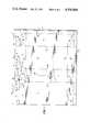
- FIG. 1is a plan view of a blank depicting one embodiment of the present invention.
- FIG. 2is a perspective view of the embodiment of FIG. 1 showing the carton in its completely sealed configuration.
- FIG. 3is a perspective view of the embodiment of FIGS. 1 and 2 showing a partial opening of the carton.
- FIG. 4is a perspective view of the embodiments of FIGS. 1 through 3 depicting the removal of the tear-off portion to open the spout.
- FIG. 5is a perspective view of the carton of FIGS. 1 through 4 depicting the spout in an open configuration.
- FIG. 6is a plan view of a blank showing another embodiment of the invention.
- FIG. 7is a perspective view of the embodiment of FIG. 6 with the spout fully opened.
- FIG. 1depicts a flat carton blank having layers of heat sealing plastic on both sides.
- the blankhas two main sidewalls 1 and 2, two end panels 3 and 4 and a side seam 5.
- An area 6the full length of the side seam is skived and hemmed during the heat seal side seaming of the blank.
- the carton blankhas two top panels 7 and 8 and two bottom panels 9 and 10.
- Panels 11 and 12are extensions of top panels 7 and 8 and panels 13 and 14 are extensions of bottom panels 9 and 10.
- the blankalso has extensions 15, 16, 17, 18 of end panels 3 and 4.
- Each end panel extensionhas two diagonal crease lines 19 in each panel.
- the main sidewalls 1 and 2 and end panels 3 and 4have vertical crease hinge lines 20 which extend between cut lines 21 and 22 and horizontal crease hinge lines 23 and 24 which extend through panels 1, 2, 3, 4 and side seam 5. It should be noted that horizontal crease hinge line 23 does not extend through end panel 3. End panel 3 and the spout forming panels 15 are divided by two arched creases 25. Top panels 11, 12, 7 and 8 (comprising the top closure) are divided by crease hinge line 26 and bottom panels 9, 10, 13 and 14 are divided by crease hinge line 27. End panel 3 has a vertical line 28 starting from cut line 21 and intersects with diagonal crease lines 29. Those crease lines also intersect vertical crease line 28 and horizontal crease line 30.
- Top panels 7 and 8have diagonal crease lines 31 separating the second portion of the lower panel from the spout forming panels 7 and 8.
- Rear upper sealing panels 11 and 12 and spout forming panel 15 of end panel 3has a cut line 32 which terminates short of each side of vertical crease line 28.
- the web of cartonsreceives an overall lamination of foil on the inside and an extruded heat sealable coating over the foil and, in a preferred embodiment on the outside as well.
- top panels 7 and 8are folded inward along hinge crease line 23.
- Spout forming panel 15 and end panel 16are folded outward on diagonal crease lines 19.
- Top upper sealing panels 11 and 12are folded to a vertical on hinge crease line 26 at which time come together in an inside surface face-to-face abutment. Heat sealing of this surface will be effected along the entire length of the vertical fin and slightly above cut line 32.
- a cutout area along the diagonal cut of line 33 which intersects at vertical cut 34 and a vertical crease extension 35 of diagonal crease lines 19is at that intersection point about 3/16" above cut line 32 to ensure sufficient area for a liquid tight seal.
- rear upper sealing panel 11 and the upper portions of end panel 4have a cut line 36 and 37 which is above cut line 21. If there were no heat sealing coating on the outside of the carton, the coated inside surface is exposed and can be sealed to the outside surface. If, however, both surfaces are coated with heat sealing material then the heat seal bond is stronger.
- FIG. 2The carton, completely sealed is shown in FIG. 2.
- the spot heat seal bond of spout forming panel 15is broken as shown in FIG. 3.
- the spout edge forming panels 38 of the upper sealing panels 11 and 12 and the tear-off portion 39 above the line of structural weakness, here cut line 32is folded upward along hinge crease line 26 at which time the paperboard will tear on a non-cut line area 40 down to hinge crease line 26.
- Cut line 32extends past vertical cut lines 41. This will allow tear-off portion 39 to begin tearing forward of the end of the cut 32 preventing a tear that could otherwise begin along hinge crease line 26.
- the tear-off portion 39is removed along cut line 32.
- the material to be tornis only the foil and the extruded heat seal coating ensuring a very positive and easy removal of tear-off portion 39 as shown in FIG. 4.
- cut line 32terminates short of each side of vertical crease line 28.
- tear-off portion 39When tear-off portion 39 is removed, the uncut portion will tear and provide a tit 49 that substantially reduces the tendency of liquid being poured slowly from a full carton to cling to the carton and dribble down along the end wall. See U.S. Pat. No. 4,327,833, Column 7, Paragraph 3.
- FIG. 6An alternate embodiment to this structure is shown in FIG. 6 as a flat blank.
- the structure as shown in FIGS. 1, 2, 3, 4, and 5is one that would be side seam sealed at the point of manufacture.
- the blank shown in FIG. 6would have the spout opening line of weakness cut during printing, receive a foil lamination on the inside and an extruded heat sealable coating over the foil and on the outside.
- the carton blanksAfter die cutting the carton blanks would be ready to ship to the point of packaging. At that point, the carton blank is formed around a mandrel. With the bottom of the carton 101 in contact with the bottom of the mandrel main sidewalls 102 and 103 fold upward on hinge crease lines 104.
- End panels 105, 106, 107 and 108fold in and around the sides of the mandrel.
- panels 109 and 110 of bottom panel 101fold downward on hinge/crease lines 111 and 112 and diagonal creases 113 and 114 fold forming a web.
- panels 115, 116, 117 and 118 of end panels 105, 106, 107 and 108are folded outward.
- a face-to-face heat sealis made along the entire length of panels 115, 116, 117 and 118. These panels are sealed against the outside of end panels 106 and 108.
- the web panels 109 and 110are folded up 180° and sealed against the outside of panels 115 and 117. The body of this structure is now formed and ready for filling.
- top panels 119 and 120are folded inward on hinge crease lines 121 and 122.
- spout forming panel 123 and sealing panel 124 of panels 105, 119 and 107 and spout forming panel 125 and sealing panel 126 of panels 106, 120 and 108are folded outward.
- these panelsare folded on hinge crease lines 121 and 122 about 80° downward toward top panel 120 and then heat sealed together in a horizontal line slightly above cut lines 129 and 130.
- top sealing panel 127is wider and projects above top sealing panel 128 in order to allow exposure of the inside surface to be sealed to the outside of top panel 120.
- the opening and function of the top and pour spoutis similar to that shown in FIGS. 4 and 5.
- FIG. 7shows a carton like that depicted in FIG. 6 completely set up and opened to illustrate the appearance and various folds and seals.
- the various interior lines of structural weaknessmay be formed by die cutting the blank, by mechanically removing a narrow layer of paperboard or by burning away a narrow layer of paperboard by means of laser radiation.
- the line of structural weaknessis formed by routing a channel into the outer surface of the blank. When such a line of structural weakness is torn, it forms upstanding fibers that lift the liquid being poured over the edge and prevent it from dribbling down the end wall and spout.
Landscapes
- Engineering & Computer Science (AREA)
- Mechanical Engineering (AREA)
- Cartons (AREA)
Abstract
Description
Claims (11)
Priority Applications (2)
| Application Number | Priority Date | Filing Date | Title |
|---|---|---|---|
| US06/548,089US4546884A (en) | 1983-11-02 | 1983-11-02 | Tear strip end closure on liquid tight carton |
| US06/724,686US4740163A (en) | 1983-11-02 | 1985-04-19 | Channel opening feature for cartons |
Applications Claiming Priority (1)
| Application Number | Priority Date | Filing Date | Title |
|---|---|---|---|
| US06/548,089US4546884A (en) | 1983-11-02 | 1983-11-02 | Tear strip end closure on liquid tight carton |
Related Child Applications (1)
| Application Number | Title | Priority Date | Filing Date |
|---|---|---|---|
| US06/724,686Continuation-In-PartUS4740163A (en) | 1983-11-02 | 1985-04-19 | Channel opening feature for cartons |
Publications (1)
| Publication Number | Publication Date |
|---|---|
| US4546884Atrue US4546884A (en) | 1985-10-15 |
Family
ID=24187361
Family Applications (1)
| Application Number | Title | Priority Date | Filing Date |
|---|---|---|---|
| US06/548,089Expired - Fee RelatedUS4546884A (en) | 1983-11-02 | 1983-11-02 | Tear strip end closure on liquid tight carton |
Country Status (1)
| Country | Link |
|---|---|
| US (1) | US4546884A (en) |
Cited By (14)
| Publication number | Priority date | Publication date | Assignee | Title |
|---|---|---|---|---|
| US4703876A (en)* | 1982-07-17 | 1987-11-03 | Tetra Pak Developpement S.A. | Package for material capable of flow |
| US4811849A (en)* | 1986-03-24 | 1989-03-14 | Ab Tetra Pak | Packing containers and blanks therefor |
| US4813546A (en)* | 1988-06-15 | 1989-03-21 | International Paper Company | Opening arrangement for gable top container |
| US4813545A (en)* | 1986-07-17 | 1989-03-21 | Mpr Corporation | Rectangular paperboard package |
| US4911306A (en)* | 1987-06-22 | 1990-03-27 | Elopak Systems A. G. | Flat top end closure for liquid containers |
| US5029751A (en)* | 1989-06-29 | 1991-07-09 | Van Den Bergh Foods Co., Division Of Conopco, Inc. | Pack made from a single-piece board blank |
| US5694746A (en)* | 1994-12-20 | 1997-12-09 | Chung; Yun H. | Paperboard package and method for forming same |
| EP0838410A1 (en)* | 1996-10-28 | 1998-04-29 | Legend Incorporation Limited | Bag-in-box container with integral pouring spout |
| US5820017A (en)* | 1994-11-16 | 1998-10-13 | Legend Incorporation Limited | Fluid containers and methods of manufacture thereof |
| US6443357B1 (en)* | 1997-11-19 | 2002-09-03 | Tetra Laval Holdings & Finance, S.A. | Packaging case and packaging material therefor |
| US20100078467A1 (en)* | 2008-10-01 | 2010-04-01 | Steve Mortimore | Product container |
| CN101137551B (en)* | 2005-02-01 | 2010-06-23 | 印刷包装国际公司 | Gusseted carton |
| US7967510B2 (en) | 2006-08-08 | 2011-06-28 | Kellogg Company | Flexible container for pourable product |
| US10124947B2 (en) | 2014-06-23 | 2018-11-13 | Graphic Packaging International, Llc | Carton with dispensing features |
Citations (24)
| Publication number | Priority date | Publication date | Assignee | Title |
|---|---|---|---|---|
| US2465949A (en)* | 1945-02-12 | 1949-03-29 | Nat Folding Box Company Inc | Sealed reclosable carton end structure |
| US3040950A (en)* | 1959-11-16 | 1962-06-26 | American Can Co | Dispensing guide |
| CA714414A (en)* | 1965-07-27 | D. Partridge Robert | Containers | |
| US3232514A (en)* | 1963-01-16 | 1966-02-01 | Tepar Ag | Filled and sealed package |
| US3333758A (en)* | 1964-06-23 | 1967-08-01 | Fr Hesser Maschinenfabrik A G | Container |
| SE300093B (en)* | 1965-11-10 | 1968-04-01 | O Christensson | |
| US3386323A (en)* | 1965-10-21 | 1968-06-04 | George Russell Smythe | Accessory device for a slitter |
| US3401608A (en)* | 1967-01-05 | 1968-09-17 | Raymond A. Labombarde | Apparatus for removing solidified coating from box blanks |
| US3404988A (en)* | 1964-11-04 | 1968-10-08 | Tetra Pak Ab | Liquid filled package with dispensing opening means |
| GB1134847A (en)* | 1965-03-04 | 1968-11-27 | Pembroke Carton & Printing Com | Improvements in or relating to lined cartons |
| SE315243B (en)* | 1966-02-04 | 1969-09-22 | Tepar Ag | |
| US3471991A (en)* | 1967-02-27 | 1969-10-14 | Tetra Pak Ab | Method of making filled and sealed packages |
| US3654842A (en)* | 1969-10-13 | 1972-04-11 | Int Paper Co | Method of making side seam sealed container |
| US3719548A (en)* | 1971-08-06 | 1973-03-06 | Ludlow Corp | Fracturable adhesive backing |
| US3795359A (en)* | 1971-11-19 | 1974-03-05 | Tetra Pak Int | Parallellepipedic package |
| US3797726A (en)* | 1971-01-11 | 1974-03-19 | Altstaedter Verpack Vertrieb | Container for liquids with an openable pouring spout |
| US3869078A (en)* | 1973-12-18 | 1975-03-04 | Ex Cell O Corp | Liquid proof flat end container with reclosable pour spout |
| US4078715A (en)* | 1973-04-24 | 1978-03-14 | Ab Ziristor | Packing container |
| US4093115A (en)* | 1974-07-15 | 1978-06-06 | Nimco Corporation | Liquid-tight flat top container |
| US4135438A (en)* | 1976-04-27 | 1979-01-23 | Yasuji Sugioka | Device for roughening the edge surface of a plurality of sheets |
| EP0014272A2 (en)* | 1979-01-15 | 1980-08-20 | Ab Tetra Pak | Parallelepipedic packaging container provided with an opening arrangement and method for the manufacture of such a container |
| US4248351A (en)* | 1977-06-20 | 1981-02-03 | Tetra Pak International Ab | Packaging container with a pouring spout |
| US4327833A (en)* | 1979-12-10 | 1982-05-04 | American Can Company | Liquid tight pouring carton |
| US4362245A (en)* | 1979-12-10 | 1982-12-07 | American Can Company | Liquid tight pouring carton |
- 1983
- 1983-11-02USUS06/548,089patent/US4546884A/ennot_activeExpired - Fee Related
Patent Citations (26)
| Publication number | Priority date | Publication date | Assignee | Title |
|---|---|---|---|---|
| CA714414A (en)* | 1965-07-27 | D. Partridge Robert | Containers | |
| US2465949A (en)* | 1945-02-12 | 1949-03-29 | Nat Folding Box Company Inc | Sealed reclosable carton end structure |
| US3040950A (en)* | 1959-11-16 | 1962-06-26 | American Can Co | Dispensing guide |
| US3040951A (en)* | 1959-11-16 | 1962-06-26 | American Can Co | Container |
| US3232514A (en)* | 1963-01-16 | 1966-02-01 | Tepar Ag | Filled and sealed package |
| US3333758A (en)* | 1964-06-23 | 1967-08-01 | Fr Hesser Maschinenfabrik A G | Container |
| US3404988A (en)* | 1964-11-04 | 1968-10-08 | Tetra Pak Ab | Liquid filled package with dispensing opening means |
| GB1134847A (en)* | 1965-03-04 | 1968-11-27 | Pembroke Carton & Printing Com | Improvements in or relating to lined cartons |
| US3386323A (en)* | 1965-10-21 | 1968-06-04 | George Russell Smythe | Accessory device for a slitter |
| SE300093B (en)* | 1965-11-10 | 1968-04-01 | O Christensson | |
| SE315243B (en)* | 1966-02-04 | 1969-09-22 | Tepar Ag | |
| US3401608A (en)* | 1967-01-05 | 1968-09-17 | Raymond A. Labombarde | Apparatus for removing solidified coating from box blanks |
| US3471991A (en)* | 1967-02-27 | 1969-10-14 | Tetra Pak Ab | Method of making filled and sealed packages |
| US3654842A (en)* | 1969-10-13 | 1972-04-11 | Int Paper Co | Method of making side seam sealed container |
| US3797726A (en)* | 1971-01-11 | 1974-03-19 | Altstaedter Verpack Vertrieb | Container for liquids with an openable pouring spout |
| US3719548A (en)* | 1971-08-06 | 1973-03-06 | Ludlow Corp | Fracturable adhesive backing |
| US3795359A (en)* | 1971-11-19 | 1974-03-05 | Tetra Pak Int | Parallellepipedic package |
| US4078715A (en)* | 1973-04-24 | 1978-03-14 | Ab Ziristor | Packing container |
| US3869078A (en)* | 1973-12-18 | 1975-03-04 | Ex Cell O Corp | Liquid proof flat end container with reclosable pour spout |
| US4093115A (en)* | 1974-07-15 | 1978-06-06 | Nimco Corporation | Liquid-tight flat top container |
| US4135438A (en)* | 1976-04-27 | 1979-01-23 | Yasuji Sugioka | Device for roughening the edge surface of a plurality of sheets |
| US4248351A (en)* | 1977-06-20 | 1981-02-03 | Tetra Pak International Ab | Packaging container with a pouring spout |
| EP0014272A2 (en)* | 1979-01-15 | 1980-08-20 | Ab Tetra Pak | Parallelepipedic packaging container provided with an opening arrangement and method for the manufacture of such a container |
| US4343402A (en)* | 1979-01-15 | 1982-08-10 | Tetra Pak International Ab | Parallelepipedic packing container provided with an opening arrangement |
| US4327833A (en)* | 1979-12-10 | 1982-05-04 | American Can Company | Liquid tight pouring carton |
| US4362245A (en)* | 1979-12-10 | 1982-12-07 | American Can Company | Liquid tight pouring carton |
Cited By (17)
| Publication number | Priority date | Publication date | Assignee | Title |
|---|---|---|---|---|
| US4703876A (en)* | 1982-07-17 | 1987-11-03 | Tetra Pak Developpement S.A. | Package for material capable of flow |
| US4811849A (en)* | 1986-03-24 | 1989-03-14 | Ab Tetra Pak | Packing containers and blanks therefor |
| EP0243598A3 (en)* | 1986-03-24 | 1991-11-13 | AB Tetra Pak | Blanks for packing containers |
| US4813545A (en)* | 1986-07-17 | 1989-03-21 | Mpr Corporation | Rectangular paperboard package |
| US4911306A (en)* | 1987-06-22 | 1990-03-27 | Elopak Systems A. G. | Flat top end closure for liquid containers |
| US4813546A (en)* | 1988-06-15 | 1989-03-21 | International Paper Company | Opening arrangement for gable top container |
| US5029751A (en)* | 1989-06-29 | 1991-07-09 | Van Den Bergh Foods Co., Division Of Conopco, Inc. | Pack made from a single-piece board blank |
| US5820017A (en)* | 1994-11-16 | 1998-10-13 | Legend Incorporation Limited | Fluid containers and methods of manufacture thereof |
| US5694746A (en)* | 1994-12-20 | 1997-12-09 | Chung; Yun H. | Paperboard package and method for forming same |
| EP0838410A1 (en)* | 1996-10-28 | 1998-04-29 | Legend Incorporation Limited | Bag-in-box container with integral pouring spout |
| US6443357B1 (en)* | 1997-11-19 | 2002-09-03 | Tetra Laval Holdings & Finance, S.A. | Packaging case and packaging material therefor |
| CN101137551B (en)* | 2005-02-01 | 2010-06-23 | 印刷包装国际公司 | Gusseted carton |
| US7967510B2 (en) | 2006-08-08 | 2011-06-28 | Kellogg Company | Flexible container for pourable product |
| US8408793B2 (en) | 2006-08-08 | 2013-04-02 | Kellogg Company | Flexible container for pourable product |
| US20100078467A1 (en)* | 2008-10-01 | 2010-04-01 | Steve Mortimore | Product container |
| US10124947B2 (en) | 2014-06-23 | 2018-11-13 | Graphic Packaging International, Llc | Carton with dispensing features |
| US10562687B2 (en) | 2014-06-23 | 2020-02-18 | Graphic Packaging International, Llc | Carton with dispensing features |
Similar Documents
| Publication | Publication Date | Title |
|---|---|---|
| US3426955A (en) | Combination bag and box | |
| US4691858A (en) | Milk carton blank and milk carton with pour spout | |
| US3580483A (en) | Membrane sealed carton | |
| US4613046A (en) | Reclosable package and carton blank | |
| US4197949A (en) | Opening of containers | |
| EP0112897B1 (en) | Linerless carton including easily openable pouring spout | |
| US4673126A (en) | Moisture barrier carton with reclosable cover | |
| US4591091A (en) | Aseptic container with tamper-resistant spout and blank therefor | |
| US4811849A (en) | Packing containers and blanks therefor | |
| US4546884A (en) | Tear strip end closure on liquid tight carton | |
| US4740163A (en) | Channel opening feature for cartons | |
| US5333781A (en) | Recloseable carton with pouring spout | |
| JPS58125443A (en) | Device concerning packing vessel | |
| US4669614A (en) | Ice cream carton and blank | |
| US5325989A (en) | Box and blank for packaging powdered soap or the like | |
| EP0253549A2 (en) | Carton with reclosable membrane liner | |
| US4732275A (en) | Openable and reclosable carton | |
| US4666044A (en) | Tear-open flap orifice on packs consisting of plastic-coated laminated material with a folded-round fillet-seam closure and a process for producing the tear-open flap orifice | |
| EP0039116B1 (en) | Liquid container with straw opening means | |
| US5080233A (en) | Gable top container having reduced opening force and method for construction therefor | |
| US4300716A (en) | Paperboard carton | |
| US3498521A (en) | Carton with plastic sealing | |
| US4911305A (en) | Tear away top structure for a rectangular paperboard container | |
| US5007542A (en) | Recloseable carton with pouring spout | |
| US3692226A (en) | Removable side wall for tightly sealed drumhead cartons |
Legal Events
| Date | Code | Title | Description |
|---|---|---|---|
| AS | Assignment | Owner name:JAMES RIVER-NORWALK, INC., RIVERPARK, P.O. BOX 600 Free format text:ASSIGNMENT OF ASSIGNORS INTEREST.;ASSIGNOR:JAMES RIVER- DIXIE/NORTHERN, INC.;REEL/FRAME:004311/0220 Effective date:19840905 | |
| AS | Assignment | Owner name:JAMES RIVER-NORWALK, INC., RIVERPARK 3A1, P.O. BOX Free format text:ASSIGNMENT OF ASSIGNORS INTEREST.;ASSIGNOR:KUCHENBECKER, MORRIS W.;REEL/FRAME:004386/0986 Effective date:19850403 | |
| FEPP | Fee payment procedure | Free format text:PAYOR NUMBER ASSIGNED (ORIGINAL EVENT CODE: ASPN); ENTITY STATUS OF PATENT OWNER: LARGE ENTITY | |
| FPAY | Fee payment | Year of fee payment:4 | |
| AS | Assignment | Owner name:JAMES RIVER PAPER COMPANY, INC., A CORP. OF VA. Free format text:MERGER;ASSIGNOR:JAMES RIVER-NORWALK, INC.;REEL/FRAME:005152/0359 Effective date:19890420 | |
| REMI | Maintenance fee reminder mailed | ||
| LAPS | Lapse for failure to pay maintenance fees | ||
| FP | Lapsed due to failure to pay maintenance fee | Effective date:19891017 | |
| STCH | Information on status: patent discontinuation | Free format text:PATENT EXPIRED DUE TO NONPAYMENT OF MAINTENANCE FEES UNDER 37 CFR 1.362 |