US4546761A - Large animal speculum holder and battery-powered illuminator - Google Patents
Large animal speculum holder and battery-powered illuminatorDownload PDFInfo
- Publication number
- US4546761A US4546761AUS06/457,434US45743483AUS4546761AUS 4546761 AUS4546761 AUS 4546761AUS 45743483 AUS45743483 AUS 45743483AUS 4546761 AUS4546761 AUS 4546761A
- Authority
- US
- United States
- Prior art keywords
- speculum
- battery
- bulb
- holder
- tubular
- Prior art date
- Legal status (The legal status is an assumption and is not a legal conclusion. Google has not performed a legal analysis and makes no representation as to the accuracy of the status listed.)
- Expired - Fee Related
Links
- 241001465754MetazoaSpecies0.000titleclaimsdescription17
- 239000004020conductorSubstances0.000claimsabstractdescription16
- 238000007789sealingMethods0.000claimsdescription4
- 238000000034methodMethods0.000claimsdescription3
- 238000005286illuminationMethods0.000description8
- 239000003814drugSubstances0.000description4
- 239000012530fluidSubstances0.000description3
- 239000000463materialSubstances0.000description3
- 230000001225therapeutic effectEffects0.000description3
- 238000005219brazingMethods0.000description2
- 238000005260corrosionMethods0.000description2
- 230000007797corrosionEffects0.000description2
- 238000002405diagnostic procedureMethods0.000description2
- 230000000694effectsEffects0.000description2
- 238000012986modificationMethods0.000description2
- 230000004048modificationEffects0.000description2
- 239000004033plasticSubstances0.000description2
- 230000001681protective effectEffects0.000description2
- 238000004659sterilization and disinfectionMethods0.000description2
- 239000000126substanceSubstances0.000description2
- 238000001356surgical procedureMethods0.000description2
- 238000002560therapeutic procedureMethods0.000description2
- 241000283690Bos taurusSpecies0.000description1
- 239000004809TeflonSubstances0.000description1
- 229920006362Teflon®Polymers0.000description1
- 239000000853adhesiveSubstances0.000description1
- 230000001070adhesive effectEffects0.000description1
- 230000003466anti-cipated effectEffects0.000description1
- 238000004140cleaningMethods0.000description1
- 239000011248coating agentSubstances0.000description1
- 238000000576coating methodMethods0.000description1
- 238000011109contaminationMethods0.000description1
- 229940079593drugDrugs0.000description1
- 229910052736halogenInorganic materials0.000description1
- 150000002367halogensChemical class0.000description1
- 230000002962histologic effectEffects0.000description1
- 230000009027inseminationEffects0.000description1
- 238000003780insertionMethods0.000description1
- 230000037431insertionEffects0.000description1
- 239000011810insulating materialSubstances0.000description1
- 230000009545invasionEffects0.000description1
- 239000007788liquidSubstances0.000description1
- 238000002483medicationMethods0.000description1
- 239000002184metalSubstances0.000description1
- 230000002906microbiologic effectEffects0.000description1
- 230000001575pathological effectEffects0.000description1
- 229920001296polysiloxanePolymers0.000description1
- 230000001012protectorEffects0.000description1
- 238000005070samplingMethods0.000description1
- 238000005476solderingMethods0.000description1
- 238000010561standard procedureMethods0.000description1
- 230000001954sterilising effectEffects0.000description1
- 238000012360testing methodMethods0.000description1
- 238000003466weldingMethods0.000description1
Images

Classifications
- A—HUMAN NECESSITIES
- A61—MEDICAL OR VETERINARY SCIENCE; HYGIENE
- A61B—DIAGNOSIS; SURGERY; IDENTIFICATION
- A61B1/00—Instruments for performing medical examinations of the interior of cavities or tubes of the body by visual or photographical inspection, e.g. endoscopes; Illuminating arrangements therefor
- A61B1/06—Instruments for performing medical examinations of the interior of cavities or tubes of the body by visual or photographical inspection, e.g. endoscopes; Illuminating arrangements therefor with illuminating arrangements
- A61B1/0661—Endoscope light sources
- A61B1/0669—Endoscope light sources at proximal end of an endoscope
Definitions
- This inventionrelates to speculums, and more particularly to a speculum holder-illuminator to be used with sterile disposable or reusable speculum tubes for large animals.
- Speculumsare well known devices which are used in the medical examination of humans and animals by their insertion into natural body orifices in order to enable exposure of internal tissue structures for diagnostic or therapeutic purposes. They are conventionally used with a supplementary source of illumination in order that the tissue structures exposed and examined may be adequately inspected and evaluated.
- the speculum holder-illuminatorSince most diagnostic decisions are based upon color, texture and form of the tissues observed, the speculum holder-illuminator must have a light source and power supply which will provide a constant high-intensity illumination with a color temperature most like sunlight over the useful life of the light source and power supply. Under field conditions, the power supply and bulb life must be sufficient to enable uninterrupted use of the instrument throughout a working day. Replacement of the power source and bulb must be easily carried out under field conditions if necessary.
- Diagnostic proceduresoften require specific testing of tissues observed at the distal end of the speculum. This may include sampling for histologic or pathologic examination or for microbiological or chemical analysis. Therapeutic or surgical procedures may require application of medications or other substances or materials.
- the speculum holder-illuminator unitmust permit the free and unencumbered passage of a variety of veterinary instruments or appliances with minimal obstruction of view and maximum illumination intensity at the distal end of the speculum tube.
- the high-intensity light sourcemust be protected to prevent direct fluid contact with the bulb. It may also be anticipated that fluid will enter the housing of the speculum holder, so all electrical connections must be sealed against fluid invasion. Such protection is needed because frequent cleaning and disinfection of the instrument will be required in normal use.
- a principal object of the present inventionis to provide a sturdily constructed speculum holder and battery-powered illuminator which will fasten to and become an integral unit with sterile disposable or reusable speculum tubes to enable veterinary type vaginal and cervical examination of large animals under field conditions.
- One object of the inventionis to provide a holder-illuminator which is completely self-contained and which, when connected to a speculum tube will permit continuous illumination of tissues and structures during the manipulation of the distal end to displace tissues or structures of interest. Manipulation of the distal end of the speculum tube while the tissues are illuminated may be accomplished with one hand free to insert diagnostic or therapeutic instruments through and guided by the lighted speculum tube.
- Another object of the inventionis to provide a speculum holder-illuminator which will be corrosion resistant, easily cleaned and disinfected or sterilized, and which will remain unaffected by the variety of liquids which are commonly used in veterinary medicine or which may be of biologic origin and which may come into contact with the speculum holder-illuminator.
- Another object of the inventionis to provide a sturdy and well protected source of constant high-intensity illumination by the use of a sub-miniature halogen cycle lamp encased and sealed into a metal housing with a protective front lens which will illuminate the tissues under observation with light of a color temperature most like sunlight in order to provide the veterinarian with constant and unaltered tissue appearances to facilitate diagnostice judgments.
- Another object of the inventionis to provide a rechargeable battery power source in the form of a battery stick which can be housed in a conveniently sized protected enclosure which will serve as the handle of the device and which will provide the needed voltage levels and ampere-hour capacity sufficient for the daily activities of the average large animal veterinarian. Further, the rechargeable battery and bulb housing may be easily replaced under field conditions, if necessary.
- Another object of the inventionis to provide a large proximal orificed speculum holder-illuminator which can allow for uninterrupted illumination of tissues while a variety of veterinary instruments and appliances are passed through the proximal end of the speculum holder-illuminator and into the speculum tube itself to accomplish the variety of diagnostic or therapeutic procedures common to veterinary medicine.
- Another object of the inventionis to provide a special tubular base bulb holder unit into which the protected bulb housing may be fitted to form a very light weight, compact speculum clip-illuminator, which may be temporarily fastened inside the proximal end of a sterile disposable or reusable speculum tube, thereby providing a constant source of high-intensity illumination without obstructing view through the proximal speculum end and enabling free passage of an instrument or appliance.
- Such clip-illuminatoris easily disinfected or sterilized and when connected to a remote, belt-supported, auxiliary battery power source of ample capacity, can supply a substantial ampere-hour capacity enabling extended field operations which may include, for example, such activities as artificial insemination.
- the speculum clip-illuminatoras a fully sterilized unit, may optionally be inserted deep into the speculum tube to intensify illumination for surgical procedures without fear of contamination.
- Another object of the inventionis to provide a remote battery power pack in which a power cord is wound on a crank-operated reel within a casing and the reel is rotatable in one direction to pay out the cord for use and rotatable in the opposite direction to store it in the casing when not in use.
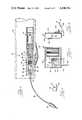
- FIG. 1is a side view of a self-powered speculum holder-illuminator illustrating one embodiment of the invention
- FIG. 2is an enlarged fragmentary partially cross-sectional view of FIG. 1;
- FIG. 3is a view of an alterna.te embodiment showing a light weight version of the invention, namely a clip-illuminator, powered by a remote battery pack supported on the belt of a user;
- FIG. 4is a fragmentary longitudinal cross-sectional view of the clip-illuminator shown in FIG. 3;
- FIG. 5is a fragmentary enlarged view of the remote battery pack shown in FIG. 3, with the front cover removed;
- FIG. 6is a side view of FIG. 5;
- FIG. 7is a fragmentary view of FIG. 5 showing the power cord retracted.
- the self-powered speculum holder-illuminator embodiment shown in FIGS. 1 and 2it comprises an illuminated speculum holder 20 and a sterile disposable or reusable tubular speculum 22.
- the speculum holder 20has a handle 24 comprising a cylindrical case with battery compartment housing 26 containing a battery compartment 28, a switch housing 29 containing a switch compartment 30, and a cylindrical speculum support sleeve 31.
- the case 26is closed at the bottom and has an upper, open end with internal threads 25.
- a battery 36preferably rechargeable, is in compartment 28. If desired, means in the form of a charging receptacle 45, shown in broken lines in FIG. 2, may be included to charge the battery in place from an external charger (not shown).
- the switch housing 29has a lower cylindrical skirt 23 with external threads 27, and an upper cylindrical neck 21, both joined by an intermediate annular wall 19.
- the neckis connected as by brazing or welding to the speculum support sleeve 31 which is at right angles to the switch housing 29.
- the lower end of skirt 23is closed by means of a wall or disk 32 of electrical insulating material. This may be sealed by adhesive or a press fit into an open end bore 33.
- the battery housing 26is detachably screw-threadedly engaged with the switch housing 29 by threads 25 and 27 for the purpose of removing or replacing battery 36.
- Switch compartment 30is thus completely sealed from battery compartment 28 by disk 32.
- An on/off switch 38is located in the switch compartment and has an operating button 40 extending through the switch housing wall.
- a first contactconsisting of a spring 35 fastened to the battery side of disk 32 engages the top terminal of battery 36.
- the springis fastened to the disk by a conductive rivet 37 which in turn is connected to one terminal of switch 38 by a first conductor 39.
- the other terminal of the switchis connected via a second conductor 41 to a lighting assembly 46 as will be described.
- the speculum support sleeve 31is open at both ends.
- the proximal endprovides a viewing opening 64.
- a counterbore at the distal endprovides a recess 66 for the speculum 22.
- the tubular speculum 22may be of any inexpensive, sterile, disposable or reusable material such as plastic or cardboard, preferably with a light-reflective inner surface and an external slick or lubricated coating of biologically safe material such as silicone or teflon.
- the proximal endmay be provided with an open-ended longitudinal slot 34.
- FIG. 2also shows a pin 70 engageable with the slot 34 to hold the speculum tube in the recess 66.
- a plain end, non-slotted speculum tubemay be used by removing the pin 70.
- An exampleis shown in U.S. Pat. No. 3,631,852 issued Jan. 4, 1972 on "Disposable Speculum For Animals".
- a lighting assembly 46comprises a permanent L-shaped base bulb holder unit 48 and a replaceable bulb housing unit 50.
- the bulb holder unithas opposite tubular leg members 52 and 54 disposed at substantially right angles to one another. These are suitably joined as by brazing or soldering.
- Vertical leg member 52is snugly inserted in bore 56 formed in neck portion 21 and is held by a set screw 58 extending through the neck wall into engagement with a flat 60 formed on the back side of the leg member. This automatically orients the lighting assembly so leg 54 is parallel to the axis of speculum support sleeve 31.
- Horizontal leg member 54has a screw socket 62 with internal threads 63 and a center contact 65 in an insulating bushing 61 which is telescopically slidable within bore 67.
- a spring 69is compressibly interposed between the bushing 61 and shoulder 71 thereby urging the second contact 65 forwardly against third contact 72 in the bulb housing 50.
- the bulb housing unit 50is completely sealed and capable of being sterilized by standard procedures. It has a plug portion 73 consisting of external threads 74 and the above-described third contact 72. The latter is centrally located in insulating bushing 75.
- a high intensity bulb 76preferably a sub-miniature halogen-cycle type, is contained within a bore 77 in the bulb housing unit 50.
- the particular bulbwhich is shown by way of illustration but not by way of limitation has an outer metallic liner 78 in grounding contact with the bulb housing unit 50. While a filament type bulb is shown, any other type may be employed so long as it produces a high light level when energized through third contact 72 and tubular casing 91.
- lhe bulbis connected to the liner 78 and the other side is connected to the third contact 72 via a wire 79 extending through the bushing 75.
- a threaded retaining ring 80holds a protective front lens or window 82 against a sealing ring 81. Screw driver slots 83 in both the retaining ring 80 and housing 50 facilitate removal of the bulb housing for replacement or sterilization.
- the bulb 76will be energized, in response to closing switch 38, by a circuit including the top battery terminal, first contact (spring) 35, conductor 39, switch 38 conductor 41, second and third contacts 65 and 72, bulb 76, liner 78, and grounding connections through the lighting assembly 46, switch housing 29, battery housing 26 and pad 42 to the bottom battery terminal.
- the spring 35 and pad 42will be sized so the battery will function satisfactorily regardless of it being placed in a conventional right side up or upside down position.
- FIGS. 3 and 4it comprises a base bulb holder unit 86 and a bulb housing unit similar to housing unit 50 already described.
- the bulb housing unit 50may be used interchangeably with the bulb holder unit 86 shown in FIG. 4 and the bulb holder unit 48 shown in FIG. 2.
- Their socket portionsare identical, making this interchangability possible.
- the bulb holder unit 86comprises a tubular body 88 with spring clip means 89 having an attachment band 90 fastened to the outside.
- the bulb holder unit 86has a screw socket 62a similar to socket 62 shown in FIG. 2. It has internal threads 63a and a center contact 65a in an insulating bushing 61a which is longitudinally slidable within a bore 67a.
- a spring 69ais compressibly interposed between shoulder 71a and the movable bushing 61a, thereby urging the contact 65a outwardly into engagement with the contact 72 on the bulb housing 50.
- a two-conductor electrical cord 92extends through a rubberlike cord protector 87 at the end of the bulb holder unit and terminates in a plug 98.
- One conductor 94is connected to contact 65a.
- Another conductor 96is grounded to the body 88.
- the clip-illuminator 85is temporarily fastened within the proximal end of a tubular speculum 22.
- the clip 89may be fitted within the speculum slot 34 as shown in FIG. 4.
- the clip-illuminator 85, cord 92 and plug 98comprises a unit which can be separately disinfected or sterilized. If the speculum is unslotted, the clip is simply hooked over the edge of the tube wall at the proximal end.
- the clip-illuminatoris energized by a remote battery power pack, preferably of very large capacity, enabling extended use without replacing or recharging the batteries.
- a remote battery power packpreferably of very large capacity, enabling extended use without replacing or recharging the batteries.
- FIGS. 5, 6 and 7.It comprises a casing 104 with a bottom opening 106 and a cover plate 108.
- a plurality of at least two batterieswhich may be similar or identical to battery 36 described above, are connected in parallel with one another and have opposite terminals connected through an on/off switch 112, brushes 114, 114, and slip rings 116, 116 to a multiple conductor power cord 118 wound upon a reel 120 journaled for manual rotation by an external crank 122.
- a socket 124 at the end of cord 118may be connected to plug 98 to energize the clip-illuminator.
- the batteries 36 in the auxiliary power pack 102will preferably be of the rechargeable type, and means may be provided for recharging them in place within the casing 104 in a conventional manner, from an external charger (not shown) through a charging receptacle 126 indicated in broken lines in FIGS. 5 and 6.
- the power pack 102is small enough to be readily portable and may be carried on a user's belt, as shown in FIG. 3, by means of a belt fastener 128 (FIG. 6).
- the clip-illuminator 85is compact, light weight and portable and makes possible a wide variety of veterinary procedures through the open tube 22 in addition to allowing observation of internal tissues.
- the operatorwill unreel the cord 118 by pulling it out of the casing 104 and connecting plug 98 into socket 124.
- the operatorcan disconnect the plug 98 and socket 124 and wind the cord back into the casing by means of the crank 122. This will store the cord 118 and plug 124 in the casing as shown in FIG. 7.
- the switch 112corresponds to the switch 38 in the self-powered embodiment shown in FIGS. 1 and 2.
- the operatorenergizes the clip-illuminator 85 by closing switch 112 on the belt supported battery power pack 102.
Landscapes
- Health & Medical Sciences (AREA)
- Life Sciences & Earth Sciences (AREA)
- Surgery (AREA)
- Nuclear Medicine, Radiotherapy & Molecular Imaging (AREA)
- Biomedical Technology (AREA)
- Optics & Photonics (AREA)
- Pathology (AREA)
- Radiology & Medical Imaging (AREA)
- Biophysics (AREA)
- Engineering & Computer Science (AREA)
- Physics & Mathematics (AREA)
- Heart & Thoracic Surgery (AREA)
- Medical Informatics (AREA)
- Molecular Biology (AREA)
- Animal Behavior & Ethology (AREA)
- General Health & Medical Sciences (AREA)
- Public Health (AREA)
- Veterinary Medicine (AREA)
- Microscoopes, Condenser (AREA)
Abstract
Description
Claims (11)
Priority Applications (1)
| Application Number | Priority Date | Filing Date | Title |
|---|---|---|---|
| US06/457,434US4546761A (en) | 1983-01-12 | 1983-01-12 | Large animal speculum holder and battery-powered illuminator |
Applications Claiming Priority (1)
| Application Number | Priority Date | Filing Date | Title |
|---|---|---|---|
| US06/457,434US4546761A (en) | 1983-01-12 | 1983-01-12 | Large animal speculum holder and battery-powered illuminator |
Publications (1)
| Publication Number | Publication Date |
|---|---|
| US4546761Atrue US4546761A (en) | 1985-10-15 |
Family
ID=23816719
Family Applications (1)
| Application Number | Title | Priority Date | Filing Date |
|---|---|---|---|
| US06/457,434Expired - Fee RelatedUS4546761A (en) | 1983-01-12 | 1983-01-12 | Large animal speculum holder and battery-powered illuminator |
Country Status (1)
| Country | Link |
|---|---|
| US (1) | US4546761A (en) |
Cited By (36)
| Publication number | Priority date | Publication date | Assignee | Title |
|---|---|---|---|---|
| US4744013A (en)* | 1987-03-19 | 1988-05-10 | Juhon Lee | Illuminable and soundable baton |
| US5165387A (en)* | 1991-02-04 | 1992-11-24 | Transidyne General Corporation | Endoscope with disposable light |
| US5506763A (en)* | 1991-09-24 | 1996-04-09 | Carley; Curtis J. | Incandescent bulb and reflector and method for making |
| US5554097A (en)* | 1994-10-05 | 1996-09-10 | United States Surgical Corporation | Surgical instrumentation kit |
| US5785648A (en)* | 1996-10-09 | 1998-07-28 | David Min, M.D., Inc. | Speculum |
| US6379296B1 (en) | 1999-03-26 | 2002-04-30 | Richard W. Baggett | Medical lighting device |
| WO2006022517A1 (en)* | 2004-08-25 | 2006-03-02 | Chan-Bok Seok | Storage battery having an illumination function |
| US20090069632A1 (en)* | 2007-09-10 | 2009-03-12 | Boston Scientific Scimed, Inc. | Medical instrument with a deflectable distal portion |
| US20090192495A1 (en)* | 2008-01-24 | 2009-07-30 | Boston Scientific Scimed, Inc. | Structure for use as part of a medical device |
| US7758203B2 (en) | 2006-04-03 | 2010-07-20 | Welch Allyn, Inc. | Power connections and interface for compact illuminator assembly |
| US20110282160A1 (en)* | 2010-05-13 | 2011-11-17 | Doheny Eye Institute | Self contained illuminated infusion cannula systems and methods and devices |
| US8142352B2 (en) | 2006-04-03 | 2012-03-27 | Welch Allyn, Inc. | Vaginal speculum assembly having portable illuminator |
| US8157728B2 (en) | 2005-04-01 | 2012-04-17 | Welch Allyn, Inc. | Vaginal speculum |
| US8388523B2 (en) | 2005-04-01 | 2013-03-05 | Welch Allyn, Inc. | Medical diagnostic instrument having portable illuminator |
| US20130102204A1 (en)* | 2010-04-20 | 2013-04-25 | Tbi | Double-locking socket for an electric bulb |
| US9307897B2 (en) | 2010-09-28 | 2016-04-12 | Obp Corporation | Disposable speculum having lateral stabilizing mechanism |
| US20160302657A1 (en)* | 2015-04-15 | 2016-10-20 | Jacqueline Marie Hussey | Dual channeled gynecologic speculum with specimen collection and diagnostic imaging capabilities |
| US9532706B2 (en) | 2014-08-07 | 2017-01-03 | Welch Allyn, Inc. | Vaginal speculum with illuminator |
| US9867602B2 (en) | 2015-02-05 | 2018-01-16 | Obp Medical Corporation | Illuminated surgical retractor |
| US9913577B2 (en) | 2010-09-28 | 2018-03-13 | Obp Medical Corporation | Speculum |
| US20180078353A1 (en)* | 2012-02-09 | 2018-03-22 | Boston Scientific Scimed, Inc. | Implants, tools, and methods for treatments of pelvic conditions |
| US10219695B2 (en) | 2006-11-10 | 2019-03-05 | Doheny Eye Institute | Enhanced visualization illumination system |
| US10278572B1 (en) | 2017-10-19 | 2019-05-07 | Obp Medical Corporation | Speculum |
| US10420538B2 (en) | 2015-02-05 | 2019-09-24 | Obp Medical Corporation | Illuminated surgical retractor |
| US10512519B2 (en) | 2018-02-20 | 2019-12-24 | Obp Medical Corporation | Illuminated medical devices |
| US10687793B2 (en) | 2017-07-18 | 2020-06-23 | Obp Medical Corporation | Minimally invasive no touch (MINT) procedure for harvesting the great saphenous vein (GSV) and venous hydrodissector and retractor for use during the MINT procedure |
| US10722621B2 (en) | 2016-07-11 | 2020-07-28 | Obp Medical Corporation | Illuminated suction device |
| US10799229B2 (en) | 2018-02-20 | 2020-10-13 | Obp Medical Corporation | Illuminated medical devices |
| USD904607S1 (en) | 2019-05-07 | 2020-12-08 | Obp Medical Corporation | Nasal retractor |
| US10881387B2 (en) | 2015-06-03 | 2021-01-05 | Obp Medical Corporation | Retractor |
| USD911521S1 (en) | 2019-02-19 | 2021-02-23 | Obp Medical Corporation | Handle for medical devices including surgical retractors |
| US10939899B2 (en) | 2015-06-03 | 2021-03-09 | Obp Medical Corporation | End cap assembly for retractor and other medical devices |
| US10952712B2 (en) | 2015-06-03 | 2021-03-23 | Obp Medical Corporation | Retractor |
| US10959609B1 (en) | 2020-01-31 | 2021-03-30 | Obp Medical Corporation | Illuminated suction device |
| US10966702B1 (en) | 2020-02-25 | 2021-04-06 | Obp Medical Corporation | Illuminated dual-blade retractor |
| US12318080B2 (en) | 2023-07-21 | 2025-06-03 | Coopersurgical, Inc. | Illuminated surgical retractor capable of hand-held operation and of being mounted to a fixed frame |
Citations (7)
| Publication number | Priority date | Publication date | Assignee | Title |
|---|---|---|---|---|
| US951285A (en)* | 1909-06-04 | 1910-03-08 | William Meyer | Speculum. |
| US1422490A (en)* | 1921-03-26 | 1922-07-11 | Stader Otto | Veterinary surgical instrument |
| US1556355A (en)* | 1924-01-09 | 1925-10-06 | Roney Grant | Veterinary instrument |
| US1635822A (en)* | 1925-03-05 | 1927-07-12 | Zeng Standard Company De | Diagnostic instrument |
| US2469857A (en)* | 1944-08-03 | 1949-05-10 | Welch Allyn Inc | Battery handle connector |
| US2668528A (en)* | 1951-11-06 | 1954-02-09 | Frick Edwin Jacob | Veterinary medical instrument |
| US3631852A (en)* | 1969-10-24 | 1972-01-04 | Fuller Lab Inc | Disposable speculum for animals |
- 1983
- 1983-01-12USUS06/457,434patent/US4546761A/ennot_activeExpired - Fee Related
Patent Citations (7)
| Publication number | Priority date | Publication date | Assignee | Title |
|---|---|---|---|---|
| US951285A (en)* | 1909-06-04 | 1910-03-08 | William Meyer | Speculum. |
| US1422490A (en)* | 1921-03-26 | 1922-07-11 | Stader Otto | Veterinary surgical instrument |
| US1556355A (en)* | 1924-01-09 | 1925-10-06 | Roney Grant | Veterinary instrument |
| US1635822A (en)* | 1925-03-05 | 1927-07-12 | Zeng Standard Company De | Diagnostic instrument |
| US2469857A (en)* | 1944-08-03 | 1949-05-10 | Welch Allyn Inc | Battery handle connector |
| US2668528A (en)* | 1951-11-06 | 1954-02-09 | Frick Edwin Jacob | Veterinary medical instrument |
| US3631852A (en)* | 1969-10-24 | 1972-01-04 | Fuller Lab Inc | Disposable speculum for animals |
Cited By (74)
| Publication number | Priority date | Publication date | Assignee | Title |
|---|---|---|---|---|
| US4744013A (en)* | 1987-03-19 | 1988-05-10 | Juhon Lee | Illuminable and soundable baton |
| US5165387A (en)* | 1991-02-04 | 1992-11-24 | Transidyne General Corporation | Endoscope with disposable light |
| US5506763A (en)* | 1991-09-24 | 1996-04-09 | Carley; Curtis J. | Incandescent bulb and reflector and method for making |
| US5554097A (en)* | 1994-10-05 | 1996-09-10 | United States Surgical Corporation | Surgical instrumentation kit |
| US5785648A (en)* | 1996-10-09 | 1998-07-28 | David Min, M.D., Inc. | Speculum |
| US6379296B1 (en) | 1999-03-26 | 2002-04-30 | Richard W. Baggett | Medical lighting device |
| WO2006022517A1 (en)* | 2004-08-25 | 2006-03-02 | Chan-Bok Seok | Storage battery having an illumination function |
| US20170172404A1 (en)* | 2005-04-01 | 2017-06-22 | Welch Allyn, Inc. | Vaginal speculum apparatus |
| US8388523B2 (en) | 2005-04-01 | 2013-03-05 | Welch Allyn, Inc. | Medical diagnostic instrument having portable illuminator |
| US9883792B2 (en) | 2005-04-01 | 2018-02-06 | Welch Allyn, Inc. | Vaginal speculum apparatus |
| US9332898B2 (en) | 2005-04-01 | 2016-05-10 | Welch Allyn, Inc. | Vaginal speculum apparatus |
| US9949633B2 (en)* | 2005-04-01 | 2018-04-24 | Welch Allyn, Inc. | Vaginal speculum apparatus |
| US11291359B2 (en)* | 2005-04-01 | 2022-04-05 | Welch Allyn, Inc. | Vaginal speculum apparatus |
| US8157728B2 (en) | 2005-04-01 | 2012-04-17 | Welch Allyn, Inc. | Vaginal speculum |
| US10376138B2 (en) | 2005-04-01 | 2019-08-13 | Welch Allyn, Inc. | Vaginal speculum apparatus |
| US12262878B2 (en) | 2005-04-01 | 2025-04-01 | Welch Allyn, Inc. | Vaginal speculum apparatus |
| US8435175B2 (en) | 2005-04-01 | 2013-05-07 | Welch Allyn, Inc. | Vaginal speculum apparatus |
| US8821395B2 (en) | 2005-04-01 | 2014-09-02 | Welch Allyn, Inc. | Vaginal speculum apparatus |
| US8142352B2 (en) | 2006-04-03 | 2012-03-27 | Welch Allyn, Inc. | Vaginal speculum assembly having portable illuminator |
| US7758203B2 (en) | 2006-04-03 | 2010-07-20 | Welch Allyn, Inc. | Power connections and interface for compact illuminator assembly |
| US10219695B2 (en) | 2006-11-10 | 2019-03-05 | Doheny Eye Institute | Enhanced visualization illumination system |
| US20090069632A1 (en)* | 2007-09-10 | 2009-03-12 | Boston Scientific Scimed, Inc. | Medical instrument with a deflectable distal portion |
| US8845522B2 (en) | 2007-09-10 | 2014-09-30 | Boston Scientific Scimed, Inc. | Medical instrument with a deflectable distal portion |
| WO2009035812A1 (en)* | 2007-09-10 | 2009-03-19 | Boston Scientific Scimed, Inc. | Medical instrument with a deflectable distal portion |
| US9462932B2 (en) | 2008-01-24 | 2016-10-11 | Boston Scientific Scimed, Inc. | Structure for use as part of a medical device |
| US20090192495A1 (en)* | 2008-01-24 | 2009-07-30 | Boston Scientific Scimed, Inc. | Structure for use as part of a medical device |
| US8864534B2 (en)* | 2010-04-20 | 2014-10-21 | Tbi | Double-locking socket for an electric bulb |
| US20130102204A1 (en)* | 2010-04-20 | 2013-04-25 | Tbi | Double-locking socket for an electric bulb |
| US9089364B2 (en)* | 2010-05-13 | 2015-07-28 | Doheny Eye Institute | Self contained illuminated infusion cannula systems and methods and devices |
| US20140357957A1 (en)* | 2010-05-13 | 2014-12-04 | Doheny Eye Institute | Self contained illuminated infusion cannula systems and methods and devices |
| US20110282160A1 (en)* | 2010-05-13 | 2011-11-17 | Doheny Eye Institute | Self contained illuminated infusion cannula systems and methods and devices |
| US10368733B2 (en) | 2010-09-28 | 2019-08-06 | Obp Medical Corporation | Speculum |
| US9913577B2 (en) | 2010-09-28 | 2018-03-13 | Obp Medical Corporation | Speculum |
| US9307897B2 (en) | 2010-09-28 | 2016-04-12 | Obp Corporation | Disposable speculum having lateral stabilizing mechanism |
| US12419510B2 (en) | 2010-09-28 | 2025-09-23 | Coopersurgical, Inc. | Speculum |
| US11744454B2 (en) | 2010-09-28 | 2023-09-05 | Obp Medical Corporation | Speculum |
| US11039909B2 (en)* | 2012-02-09 | 2021-06-22 | Boston Scientific Scimed, Inc. | Implants, tools, and methods for treatments of pelvic conditions |
| US20180078353A1 (en)* | 2012-02-09 | 2018-03-22 | Boston Scientific Scimed, Inc. | Implants, tools, and methods for treatments of pelvic conditions |
| US9532706B2 (en) | 2014-08-07 | 2017-01-03 | Welch Allyn, Inc. | Vaginal speculum with illuminator |
| US10945594B2 (en) | 2014-08-07 | 2021-03-16 | Welch Allyn, Inc. | Vaginal speculum with illuminator |
| US11197662B2 (en) | 2015-02-05 | 2021-12-14 | Obp Surgical Corporation | Illuminated surgical retractor |
| US12089829B2 (en) | 2015-02-05 | 2024-09-17 | Obp Surgical Corporation | Illuminated surgical retractor |
| US10420538B2 (en) | 2015-02-05 | 2019-09-24 | Obp Medical Corporation | Illuminated surgical retractor |
| US10420540B2 (en) | 2015-02-05 | 2019-09-24 | Obp Medical Corporation | Illuminated surgical retractor |
| US12329370B2 (en) | 2015-02-05 | 2025-06-17 | Coopersurgical, Inc. | Illuminated surgical retractor |
| US11439379B2 (en) | 2015-02-05 | 2022-09-13 | Obp Surgical Corporation | Illuminated surgical retractor |
| US9867602B2 (en) | 2015-02-05 | 2018-01-16 | Obp Medical Corporation | Illuminated surgical retractor |
| US20160302657A1 (en)* | 2015-04-15 | 2016-10-20 | Jacqueline Marie Hussey | Dual channeled gynecologic speculum with specimen collection and diagnostic imaging capabilities |
| US10881387B2 (en) | 2015-06-03 | 2021-01-05 | Obp Medical Corporation | Retractor |
| US10939899B2 (en) | 2015-06-03 | 2021-03-09 | Obp Medical Corporation | End cap assembly for retractor and other medical devices |
| US11622756B2 (en) | 2015-06-03 | 2023-04-11 | Obp Surgical Corporation | End cap assembly for retractor and other medical devices |
| US10952712B2 (en) | 2015-06-03 | 2021-03-23 | Obp Medical Corporation | Retractor |
| US10966699B2 (en) | 2015-06-03 | 2021-04-06 | Obp Medical Corporation | Retractor |
| US12201287B2 (en) | 2015-06-03 | 2025-01-21 | Coopersurgical, Inc. | Retractor |
| US11717374B2 (en) | 2016-07-11 | 2023-08-08 | Obp Surgical Corporation | Illuminated suction device |
| US10722621B2 (en) | 2016-07-11 | 2020-07-28 | Obp Medical Corporation | Illuminated suction device |
| US10687793B2 (en) | 2017-07-18 | 2020-06-23 | Obp Medical Corporation | Minimally invasive no touch (MINT) procedure for harvesting the great saphenous vein (GSV) and venous hydrodissector and retractor for use during the MINT procedure |
| US11540817B2 (en) | 2017-07-18 | 2023-01-03 | Obp Surgical Corporation | Minimally invasive no touch (MINT) procedure for harvesting the great saphenous vein (GSV) and venous hydrodissector and retractor for use during the mint procedure |
| US10441155B2 (en) | 2017-10-19 | 2019-10-15 | Obp Medical Corporation | Medical devices with battery removal |
| US11253145B2 (en) | 2017-10-19 | 2022-02-22 | Obp Medical Corporation | Speculum |
| US12383129B2 (en) | 2017-10-19 | 2025-08-12 | Coopersurgical, Inc. | Medical devices with battery removal |
| US10912455B2 (en) | 2017-10-19 | 2021-02-09 | Obp Medical Corporation | Medical devices with battery removal |
| US10278572B1 (en) | 2017-10-19 | 2019-05-07 | Obp Medical Corporation | Speculum |
| US11744568B2 (en) | 2018-02-20 | 2023-09-05 | Obp Surgical Corporation | Illuminated medical devices |
| US10799229B2 (en) | 2018-02-20 | 2020-10-13 | Obp Medical Corporation | Illuminated medical devices |
| US10512519B2 (en) | 2018-02-20 | 2019-12-24 | Obp Medical Corporation | Illuminated medical devices |
| USD911521S1 (en) | 2019-02-19 | 2021-02-23 | Obp Medical Corporation | Handle for medical devices including surgical retractors |
| USD904607S1 (en) | 2019-05-07 | 2020-12-08 | Obp Medical Corporation | Nasal retractor |
| US12246124B2 (en) | 2020-01-31 | 2025-03-11 | Coopersurgical, Inc. | Illuminated suction device |
| US10959609B1 (en) | 2020-01-31 | 2021-03-30 | Obp Medical Corporation | Illuminated suction device |
| US11617822B2 (en) | 2020-01-31 | 2023-04-04 | Obp Surgical Corporation | Illuminated suction device |
| US10966702B1 (en) | 2020-02-25 | 2021-04-06 | Obp Medical Corporation | Illuminated dual-blade retractor |
| US11622758B2 (en) | 2020-02-25 | 2023-04-11 | Obp Surgical Corporation | Illuminated dual-blade retractor |
| US12318080B2 (en) | 2023-07-21 | 2025-06-03 | Coopersurgical, Inc. | Illuminated surgical retractor capable of hand-held operation and of being mounted to a fixed frame |
Similar Documents
| Publication | Publication Date | Title |
|---|---|---|
| US4546761A (en) | Large animal speculum holder and battery-powered illuminator | |
| US4643172A (en) | Luminescent tongue depressor | |
| US6379296B1 (en) | Medical lighting device | |
| US6428180B1 (en) | Surgical illumination device and method of use | |
| US6692432B1 (en) | Hand-held portable camera for producing video images of an object | |
| US6130520A (en) | Diagnostic instrument system | |
| US5060633A (en) | Laryngoscope blade | |
| US8157728B2 (en) | Vaginal speculum | |
| US5337735A (en) | Fiber-lighted stylet | |
| US4993945A (en) | Heated dental mirror | |
| CN101217911B (en) | Colposcope | |
| US20040184288A1 (en) | Illumination assembly having fluid-tight seal | |
| WO1994003101A1 (en) | Laryngoscope having removable blade assembly containing lamp | |
| JPS62243532A (en) | Immersible laryngoscope | |
| CA2188372A1 (en) | Lamp with retractable universal bulb for fishing rods | |
| JP3066528U (en) | Oral endoscope | |
| GB2257632A (en) | Skin treatment device | |
| US2787937A (en) | Magnifying receptacle for clinical thermometers and the like | |
| US8465423B2 (en) | Portable diagnostic instrument and a method for its use | |
| EP0813795A1 (en) | Imaging device | |
| EP0269048B1 (en) | Stethoscope | |
| US20060057535A1 (en) | Cordless intraoral dental examination instrument having non-plano mirror | |
| JP3708392B2 (en) | Endoscope battery-type light source device | |
| JP2002165388A (en) | Light source device for endoscope | |
| US3071682A (en) | Attachment for diagnostic instrument |
Legal Events
| Date | Code | Title | Description |
|---|---|---|---|
| AS | Assignment | Owner name:MCCULLOUGH CARTWRIGHT PHARMACEUTICAL CORPORATION 2 Free format text:ASSIGNMENT OF ASSIGNORS INTEREST.;ASSIGNOR:MC CULLOUGH, ROBERT J.;REEL/FRAME:004083/0252 Effective date:19830106 | |
| FEPP | Fee payment procedure | Free format text:PAYOR NUMBER ASSIGNED (ORIGINAL EVENT CODE: ASPN); ENTITY STATUS OF PATENT OWNER: LARGE ENTITY | |
| AS | Assignment | Owner name:ZOECON CORPORATION, 12005 FORD ROAD, DALLAS, TEXAS Free format text:ASSIGNMENT OF ASSIGNORS INTEREST.;ASSIGNOR:MC CULLOUGH CARTWRIGHT PHARMACEUTICAL CORPORATION;REEL/FRAME:004931/0928 Effective date:19880811 | |
| FEPP | Fee payment procedure | Free format text:PAT HLDR NO LONGER CLAIMS SMALL ENT STAT AS SMALL BUSINESS (ORIGINAL EVENT CODE: LSM2); ENTITY STATUS OF PATENT OWNER: LARGE ENTITY | |
| REMI | Maintenance fee reminder mailed | ||
| FPAY | Fee payment | Year of fee payment:4 | |
| SULP | Surcharge for late payment | ||
| REMI | Maintenance fee reminder mailed | ||
| LAPS | Lapse for failure to pay maintenance fees | ||
| FP | Lapsed due to failure to pay maintenance fee | Effective date:19891017 | |
| STCH | Information on status: patent discontinuation | Free format text:PATENT EXPIRED DUE TO NONPAYMENT OF MAINTENANCE FEES UNDER 37 CFR 1.362 |