US4546212A - Data/voice adapter for telephone network - Google Patents
Data/voice adapter for telephone networkDownload PDFInfo
- Publication number
- US4546212A US4546212AUS06/640,308US64030884AUS4546212AUS 4546212 AUS4546212 AUS 4546212AUS 64030884 AUS64030884 AUS 64030884AUS 4546212 AUS4546212 AUS 4546212A
- Authority
- US
- United States
- Prior art keywords
- telephone line
- telephone
- port
- adapter
- filter
- Prior art date
- Legal status (The legal status is an assumption and is not a legal conclusion. Google has not performed a legal analysis and makes no representation as to the accuracy of the status listed.)
- Expired - Fee Related
Links
- 230000008878couplingEffects0.000claimsdescription7
- 238000010168coupling processMethods0.000claimsdescription7
- 238000005859coupling reactionMethods0.000claimsdescription7
- 230000011664signalingEffects0.000claimsdescription5
- 239000003990capacitorSubstances0.000description10
- 238000010586diagramMethods0.000description7
- 230000000007visual effectEffects0.000description4
- 238000009434installationMethods0.000description3
- 230000003287optical effectEffects0.000description2
- 230000005540biological transmissionEffects0.000description1
- 230000008859changeEffects0.000description1
- 238000010276constructionMethods0.000description1
- 230000009977dual effectEffects0.000description1
- 238000001914filtrationMethods0.000description1
- 230000004048modificationEffects0.000description1
- 238000012986modificationMethods0.000description1
- 230000010363phase shiftEffects0.000description1
- 239000007787solidSubstances0.000description1
Images


Classifications
- H—ELECTRICITY
- H04—ELECTRIC COMMUNICATION TECHNIQUE
- H04M—TELEPHONIC COMMUNICATION
- H04M11/00—Telephonic communication systems specially adapted for combination with other electrical systems
- H04M11/06—Simultaneous speech and data transmission, e.g. telegraphic transmission over the same conductors
- H04M11/062—Simultaneous speech and data transmission, e.g. telegraphic transmission over the same conductors using different frequency bands for speech and other data
Definitions
- the present inventionrelates generally to communication equipment and more particularly to an adapter which provides for the simultaneous exchange of digital data and voice information over a single telephone line.
- Telephone linesare commonly used to provide a data communication link between computers and the like.
- a modem(acronym for modulator/demodulator) is used to both convert the digital data from the computer to analog signals capable of being transmitted over telephone lines and to convert analog signals received from the telephone lines to digital data to be forwarded to the computer.
- the present inventionpermits the simultaneous exchange of voice and computer data over a single telephone line.
- the inventionmay be easily incorporated into an existing network with little or no modifications of existing equipment.
- a data/voice adapter apparatusfor use in a telephone network having a plurality of stations interconnected by telephone lines is disclosed.
- Each stationincludes a first communication device, such as computer and an associated modem, and a second communication device, such as a telephone handset.
- the subject adapter apparatushas a first port to be coupled to the computer modem, a second port to be coupled to the telephone handset and a third port to be coupled to the telephone line.
- the subject apparatusalso includes a first signal path, for passing signals having a frequency above a first predetermined frequency.
- the first signal pathpreferably is in the form of a bi-directional high pass filter. In another embodiment, the first signal path is not filtered.
- a second signal pathwhich passes signals having a frequency below a second predetermined frequency, the second signal path preferably being in the form of a bi-directional low pass filter.
- a switch meansis provided which is switchable between first and second modes.
- the first modewhich can be referred to as the split mode, cause the first signal path to be coupled between the telephone line port and the modem port and the second signal path to be coupled between the telephone line port and the telephone handset port.
- the switch means in the second modewhich can be referred to the dial mode, the telephone line, modem and telephone handset ports of the subject apparatus are coupled together.
- the first and second predetermined frequencies associated with the two signal pathsare both typically 800 Hertz.
- a relatively low frequency channelis provided for voice communications between stations utilizing the telephone handsets.
- a relatively high frequency channelis provided for data communications between the same stations using the modems.
- FIG. 1is a simplified block diagram of an exemplary communication network comprised of three separate stations utilizing the subject invention.
- FIG. 2is a block diagram of the data/voice adapter in accordance with the present invention.
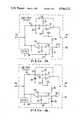
- FIG. 3is a schematic circuit diagram of the bi-directional high pass filter used in the subject data/voice adapter.
- FIG. 4is a schematic circuit diagram of the bi-directional low pass filter used in the subject data/voice adapter.
- FIG. 5is a block diagram of the call alert circuit used in the subject data/voice adapter.
- FIG. 6is a block diagram of the ringer circuit used in the subject data/voice adapter.
- FIG. 7is a schematic diagram of the split/dial switch of the subject invention showing the switch in the split mode.
- FIG. 1shows an exemplary telephone network having three separate stations which are capable of communicating with one another over telephone lines.
- Each stationincludes a computer 10 which is coupled to a modem 12.
- Modem 12is, in turn, coupled to a data/voice adapter 16, to be subsequently described, as represented by line 14.
- Each stationfurther includes one or more telephone handsets 22 which are also coupled to data/voice adapter 16, as represented by line 24.
- Data/voice adapter 16is coupled to the telephone company telephone lines, generally designated by the numeral 20, as represented by line 18.
- Adapter 16includes a split/dial switch which may be comprised of various separate mechanical or electronic switches.
- One terminal of switch 26is connected to the telephone company lines as represented by line 18.
- a second terminal of the switchis connected to the modem 12, as indicated by line 14, and a third terminal of the switch is connected to telephone handset 22, as indicated by line 24.
- Adapter 16further includes a bi-directional high pass filter 30 and a bi-directional low pass filter 32. Filters 30 and 32 have a common port which is coupled to a fourth terminal of split/dial switch 26, as represented by line 28.
- High pass filter 30has a second port which is coupled to a fifth terminal of switch 26, as represented by line 40, and low pass filter 32 has a second port which is connected to still another terminal of switch 26, as represented by line 38.
- Bi-directional high pass filter 30has a low frequency cutoff point of approximately 800 Hertz. Thus, only signal componets having a frequency in excess of 800 Hertz present at either port will be outputted to the opposite port.
- Bi-directional low pass filter 32has a high frequency cutoff point of approximately 800 Hertz. Thus, only signals having a frequency component of 800 Hertz or less will be passed from one port of filter 32 to the opposite port.
- Adapter 16further includes a call alert circuit as represented by block 34, which is connected to the fourth terminal of switch 26 by way of line 28.
- call alert circuit 34is used to call another station in the network or to detect that a call originating from another station is being made to the station associated with the circuit.
- Switch 26is further coupled to a ringer circuit represented by block 36 by way of line 28. Ringer circuit 36 causes a audible and a visual signal to be produced when a call to the station is being made.
- switch 26when switch 26 is in the split position, lines 18 and 14 are coupled together through bi-directional high pass filter 30. Thus, only signals having a frequency component in excess of 800 Hertz are passed between the telephone line and the modem.
- switch 26couples the telephone line and the telephone set together through bi-directional low pass filter 32. Accordingly, only signals having a frequency component less than 800 Hertz are exchanged between the telephone line and the telephone set.
- Switch 26also serves to couple the call alert circuit 34 and ringer circuit 36 directly to the telephone line in this mode.
- split/dial switch 26When split/dial switch 26 is in the dial position, the telephone line is coupled directly to both the modem and the telephone set. In this mode, filters 30 and 32, call alert circuit 34 and ringer circuit 36 are switched out of the system.
- bi-directional high pass filter 30is preferably comprised of two identical uni-directional active high pass filters connected in parallel in opposite directions.
- the filter for coupling signals from the telephone line to the modemincludes a conventional operational amplifier 42.
- the non-inverting input of amplifier 42is connected to a positive supply voltage +V cc by way of a resistor 44.
- the inverting input of amplifier 42is connected to the amplifier output through a resistor 46.
- the inverting inputis also coupled to line 28 through series-connected capacitors 50 and 52.
- a resistor 48is connected between the juncture of capacitors 50 and 52 and ground and a third capacitor 54 is connected between the juncture and the output of the amplifier.
- the output of amplifier 42is also conencted to line 40.
- the second uni-directional active high pass filter which couples signals from the modem to the telephone linealso includes a conventional operational amplifier 56.
- the non-inverting input of amplifier 56is coupled to positive supply voltage +V cc through a resistor 58.
- the inverting input of amplifier 56is connected to the output of the amplifier through resistor 66.
- the inverting inputis also coupled to line 40 through a pair of series-connected capacitors 60 and 68.
- the juncture of capacitors 60 and 68is connected to ground through a resistor 62 and connected to the output of amplifier 56 through capacitor 64.
- the output of amplifier 56is also connected to line 28.
- a seize circuit represented by block 98is connected between line 28 and ground. The purpose of seize circuit 98 is to seize the telephone line when an incoming call is answered by the modem.
- FIG. 4shows the circuit details of bi-directional low pass filter 32.
- Low pass filter 32also includes a pair of identical parallel-connected active filters, both being low pass filters with a cutoff point of 800 Hertz.
- Signals present on line 28 from the telephone lineare coupled to line 38 of the telephone set by way of a uni-directional low pass active filter which includes a conventional operational amplifier 70.
- the non-inverting input of amplifier 70is connected to a positive supply voltage +V cc by way of a resistor 72.
- the inverting input of amplifier 70is connected to the output of the amplifier by way of capacitor 82, with the output of the amplifier also being coupled to line 38.
- the inverting input of amplifier 70is coupled to line 28 through a pair of series-connected resistors 74 and 78.
- the connection between resistors 74 and 78is coupled to ground through a capacitor 80 and to the output of amplifier 70 by way of resistor 76.
- Signals present on line 38 from the telephone setare coupled to the telephone line through line 28 by way of a second uni-directional low pass filter which includes a conventional, operational amplifier 84 having a non-inverting input which is connected to positive supply voltage +V cc through a resistor 86.
- the inverting input of amplifier 84is connected to the output of the amplifier through capacitor 96, with the output of the amplifier also being connected to line 28.
- the inverting input of amplifier 84is coupled to line 38 through a pair of series-connected resistors 88 and 92, with the connection between the two resistors being coupled to ground through a capacitor 90 and coupled to the output of the amplifier by way of a resistor 94.
- Seize circuit 100is provided which is connected between line 28 and ground and serves to seize the telephone line when an incoming call is answered by the telephone handset.
- call alert circuit 34serves the function of signaling another station of the network when a call is to be made and detecting alert signals sent by other stations.
- the circuitonly functions after a telephone connection has been established by using conventional dialing signals produced by either modem 12 or telephone handset 22.
- Alert circuit 34is provided with an oscillator, represented by block 110, having an output frequency below the cutoff frequency of filters 30 and 32, typically 600 Hertz.
- the output of oscillator 110is connected to a buffer circuit represented by block 114.
- Buffer circuit 114includes an internal buffer amplifier followed by an impedance matching transformer which matches the impedance of the call alert circuit to that of the telephone line, such impedence preferably being greater than 900 ohms.
- the output of buffer circuit 114is connected to line 28 through a single pole double throw switch 102.
- Call alert circuit 34further includes a tone decoder circuit represented by block 106.
- Decoder circuit 106which typically includes a phased lock loop, produces an output signal on line 107 when a 600 Hertz tone produced by a call alert circuit of another station is present on the telephone line. The output signal is forwarded to a flasher/beeper circuit represented by block 108 which includes an audio transducer and a flasher for producing an audible and visual signal when a tone is detected.
- An isolator circuit 104is connected between line 28, through switch 102, and the input of tone decoder 106.
- Isolator 104includes an optical coupler which serves to electrically isolate decoder 106 from the telephone line. Switch 102 normally couples the tone decoder 106 to the telephone line, with actuation of the switch causing the decoder to be disconnected and the output of oscillator 110 to be connected to the line.
- ringer circuit 36includes a ring detector represented by block 118.
- Ring detector 118produces an output signal when a ringing signal is present on the telephone line.
- Detector 118preferably includes a phase lock loop set to the frequency of the ringing signal, typically 20 Hertz.
- the output of detector 118is connected to a flasher/beeper circuit 120 similar to circuit 108 of the call alert circuit. Flasher/beeper 128 produces an audible and visual signal when ring detector circuit 118 produces an output.
- An isolator circuit 116is disposed between the input of ring detector 118 and line 28. Circuit 116 includes an optical isolator and serves to electrically isolate the ring detector from the telephone line.
- Switch 26also may include an optional dialing signal detect circuit 131 which is connected to both the modem line 14 and the telephone handset line 24. Circuit 131 detects the presence of dialing signals on lines 14 and 24 and causes switch 26 to switch from the split mode to the dial mode.
- FIG. 7The five pairs of commonly-actuated make before break switch contacts are shown in FIG. 7 in the split position with contacts 122 and 124 being open and contacts 126, 128 and 130 being closed.
- contacts 122 and 124When switch 26 is actuated to the dial position, contacts 122 and 124 are closed and contacts 126, 128 and 130 are open.
- Switch 26is normally in the split mode.
- dial detect circuit 131causes switch 26 to immediately switch to the dial state. If circuit 131 is deleted, switch 26 is implemented to be manually actuated prior to dialing.
- a typical telephone linehas a bandwidth which extends approximately from 0-3 kHz.
- the subject adaptersplits the band pass of the telephone line into two frequency channels, including a low frequency channel and a high frequency channel.
- the low frequency channelextends approximately from 0-800 Hz and is used for voice communication.
- the high frequency channelextends approximately from 800-3 kHz and is used for data communications. Inasmuch as the primary components of human voice fall between 80 and 400 Hertz, the low frequency channel has more than sufficient bandwidth.
- Tables 1 and 2set forth the operating frequencies of two types of standard modems commonly used on telephone lines.
- Table 1relates to a 0-300 baud modem which utilizes frequency shift keying (FSK) and Table 2 relates to a 1200 baud modem which utilizes phase shift modulation.
- FSKfrequency shift keying
- Table 2relates to a 1200 baud modem which utilizes phase shift modulation.
- the modemWhen the 0-300 baud modem has originated a call, the modem output frequency shifts between 1270 Hertz and 1070 Hertz in the transit mode and between 2225 and 2025 Hertz in the receive mode.
- the modemhas answered a call, the output frequency shifts between 2225 Hertz and 2025 Hertz in the transmit mode and 1270 Hertz and 1070 Hertz in the receive mode.
- the phase shifted output frequencyis at 1200 Hertz when transmitting and 2400 Hertz when receiving.
- the output frequencyis at 2400 Hertz when transmitting and 1200 Hertz when receiving.
- dialing signalsare produced either by modem 12 or telephone handset 22. Such dialing signals are detected by the dial detector circuit 131 in the split-dial switch 26 thereby causing the switch to change from the split mode to the dial mode. In the event the dial detector circuit is deleted, switch 26 must be manually actuated to the dial mode before dialing is commenced. Contact pairs 122 and 124 of switch 26 are closed in the dial mode thereby connecting the modem and the telephone handset directly to the telephone line, so as to bypass filters 30 and 32.
- the resultant ringing signalswill be present on the line 18 connected to the data/voice adapter 16 of the station.
- the split/dial switch 26 of the stationis normally in the split mode, therefore, the ringing signals will be coupled through contact pairs 126 of the switch to ringer circuit 36 by way of line 28.
- the ringing signalswill be coupled to the ring detector circuit 118 through isolator circuit 116. Detector circuit 118 will then cause flasher/beeper circuit 120 to emit an audible and visual signal.
- the callwill then be answered by either the modem 12 or telephone handset 22. In the event the call is answered by the modem, the modem will cause seize circuit 98 (FIG.
- the dial detect circuit 131will cause the split/dial switch 26 of the originating station to revert back to the normal split mode.
- switches 26 of both the originating and answering stationswill be in the split mode at this time.
- Voice communication by way of the telephone handsetsis then carried out over the low frequency channel. Meanwhile, data communication between the two modems can be carried out over the high frequency channel.
- the call alert circuitis activated by manually actuating switch 102 (FIG. 5) thereby causing the 600 Hertz tone out of buffer 114 to be connected to line 28 which is connected to the telephone line 18 by way of split/dial switch 26.
- the toneis received by the call alert circuit 34 of the receiving station and the 600 Hertz tone decoder circuit 106 causes flasher/beeper circuit 108 to signal the operator to pick up the telephone handset. Note that the frequency used by the call alert circuit 34 is less than 800 Hertz, therefore the tone will not interfere with data transmissions on the high frequency channel.
- High pass filter 30provides two functions. At the transmitting end, the filter prevents the data signals on the high frequency channel from entering into the low frequency channel. At the receiving end, the high pass filter further prevents the voice signals from being received by the modem. A similar but complimentary function is performed by low pass filter 32. The low pass filter at the transmitting end prevents the voice signals from entering the high frequency channel and, at the receiving end, prevents the data signals being received by the telephone set.
- the bi-directional high pass filter 30is replaced with a short circuit. In that event, it would be necessary to utilize bi-directional low pass filters having a sharp cut-off frequency since there will not be a high pass filter at the receiving end to further ensure that signals on the low frequency channel are not received by the modem.
- a bi-directional twelfth order low pass filter having a low frequency cut off of approximately 800 Hzhas been found suitable for the present application in the event the high pass filter is to be deleted.
- Each half of the twelfth order bi-directional filtermay be constructed utilizing three dual operational amplifier circuits manufactured by Texas Instruments under the designation TI1458.
- a total of six series-connected active filter stagesare used for each half of the filter, with each stage including an operational amplifier and associated RC components configured essentially the same as the single stage active filters depicted in FIG. 4.
Landscapes
- Engineering & Computer Science (AREA)
- Computer Networks & Wireless Communication (AREA)
- Signal Processing (AREA)
- Telephonic Communication Services (AREA)
- Telephone Function (AREA)
Abstract
Description
TABLE 1 ______________________________________ 0-300 BAUD MODEM FREQUENCIES MARK (1) SPACE (0) ______________________________________ ORIGINATE Transmit 1270 Hz 1070 Hz Receive 2225 Hz 2025 Hz ANSWER Transmit 2225 Hz 2025 Hz Receive 1270 Hz 1070 Hz ______________________________________
TABLE 2 ______________________________________ 1200 BAUD MODEM FREQUENCIES TRANSMIT RECEIVE ______________________________________ ORIGINATE 1200 Hz 2400 Hz ANSWER 2400 Hz 1200 Hz ______________________________________
Claims (14)
Priority Applications (1)
| Application Number | Priority Date | Filing Date | Title |
|---|---|---|---|
| US06/640,308US4546212A (en) | 1984-03-08 | 1984-08-13 | Data/voice adapter for telephone network |
Applications Claiming Priority (2)
| Application Number | Priority Date | Filing Date | Title |
|---|---|---|---|
| US58737084A | 1984-03-08 | 1984-03-08 | |
| US06/640,308US4546212A (en) | 1984-03-08 | 1984-08-13 | Data/voice adapter for telephone network |
Related Parent Applications (1)
| Application Number | Title | Priority Date | Filing Date |
|---|---|---|---|
| US58737084AContinuation-In-Part | 1984-03-08 | 1984-03-08 |
Publications (1)
| Publication Number | Publication Date |
|---|---|
| US4546212Atrue US4546212A (en) | 1985-10-08 |
Family
ID=27080007
Family Applications (1)
| Application Number | Title | Priority Date | Filing Date |
|---|---|---|---|
| US06/640,308Expired - Fee RelatedUS4546212A (en) | 1984-03-08 | 1984-08-13 | Data/voice adapter for telephone network |
Country Status (1)
| Country | Link |
|---|---|
| US (1) | US4546212A (en) |
Cited By (82)
| Publication number | Priority date | Publication date | Assignee | Title |
|---|---|---|---|---|
| US4689814A (en)* | 1986-05-29 | 1987-08-25 | Warner Ii Charles L | External device interface for an electronic telephone |
| US4873715A (en)* | 1986-06-10 | 1989-10-10 | Hitachi, Ltd. | Automatic data/voice sending/receiving mode switching device |
| US4953206A (en)* | 1986-11-17 | 1990-08-28 | At&T Bell Laboratories | Methods of and apparatus for providing substantially error-free transmitted data |
| US4985892A (en)* | 1984-06-01 | 1991-01-15 | Xerox Corporation | Baseband local area network using ordinary telephone wiring |
| US4987586A (en)* | 1987-07-31 | 1991-01-22 | Compaq Computer Corporation | Modem-telephone interconnect |
| US5023903A (en)* | 1988-05-09 | 1991-06-11 | Bowen Frederic W | Voice and data telecommunications apparatus |
| US5065425A (en)* | 1988-12-23 | 1991-11-12 | Telic Alcatel | Telephone connection arrangement for a personal computer and a device for such an arrangement |
| US5267245A (en)* | 1990-03-07 | 1993-11-30 | Hitachi, Ltd. | ISDN communication control unit and control method |
| EP0653870A1 (en)* | 1993-11-12 | 1995-05-17 | AT&T Corp. | Call establishment for simultaneous analog and digital communications |
| US5436930A (en)* | 1993-06-14 | 1995-07-25 | At&T Corp. | Simultaneous analog and digital communications with a selection of different signal point constellations based on signal energy |
| US5440585A (en)* | 1993-06-14 | 1995-08-08 | At&T Corp. | Applications of simultaneous analog and digital communication |
| US5448555A (en)* | 1993-06-14 | 1995-09-05 | At&T Corp. | Simultaneous analog and digital communication |
| US5452289A (en)* | 1993-01-08 | 1995-09-19 | Multi-Tech Systems, Inc. | Computer-based multifunction personal communications system |
| US5453986A (en)* | 1993-01-08 | 1995-09-26 | Multi-Tech Systems, Inc. | Dual port interface for a computer-based multifunction personal communication system |
| US5475691A (en)* | 1993-11-15 | 1995-12-12 | At&T Corp. | Voice activated date rate change in simultaneous voice and data transmission |
| US5475713A (en)* | 1993-06-14 | 1995-12-12 | At&T Corp. | Shaped signal spaces in a simultaneous voice and data system |
| US5521942A (en)* | 1993-06-14 | 1996-05-28 | At&T Corp. | Method for increasing the dynamic range of a signal in a simultaneous voice and data system by the use of overlapping signal point regions and trellis coding |
| US5535204A (en)* | 1993-01-08 | 1996-07-09 | Multi-Tech Systems, Inc. | Ringdown and ringback signalling for a computer-based multifunction personal communications system |
| US5537436A (en)* | 1993-06-14 | 1996-07-16 | At&T Corp. | Simultaneous analog and digital communication applications |
| US5537441A (en)* | 1993-06-14 | 1996-07-16 | At&T Corp. | Controlled simultaneous analog and digital communication |
| US5546395A (en)* | 1993-01-08 | 1996-08-13 | Multi-Tech Systems, Inc. | Dynamic selection of compression rate for a voice compression algorithm in a voice over data modem |
| US5550905A (en)* | 1994-10-26 | 1996-08-27 | Lucent Technologies Inc. | Method and apparatus for delivering calls and caller identification information to multi-line users |
| US5559791A (en)* | 1993-06-14 | 1996-09-24 | Lucent Technologies Inc. | Companding of voice signal for simultaneous voice and data transmission |
| US5617423A (en)* | 1993-01-08 | 1997-04-01 | Multi-Tech Systems, Inc. | Voice over data modem with selectable voice compression |
| GB2306818A (en)* | 1995-10-31 | 1997-05-07 | Mitsubishi Electric Corp | Portable analog/digital radio transmitter/receiver with switchable filters |
| US5642379A (en)* | 1993-06-14 | 1997-06-24 | Paradyne Corporation | Technique for modulating orthogonal signals with one or more analog or digital signals |
| WO1997020396A3 (en)* | 1995-11-27 | 1997-07-10 | Analog Devices Inc | Pots splitter assembly with improved transhybrid loss for digital subscriber loop transmission |
| US5682386A (en)* | 1994-04-19 | 1997-10-28 | Multi-Tech Systems, Inc. | Data/voice/fax compression multiplexer |
| US5684834A (en)* | 1993-06-14 | 1997-11-04 | Paradyne Corporation | Simultaneous analog and digital communication using fractional rate encoding |
| US5719923A (en)* | 1993-06-14 | 1998-02-17 | Paradyne Corporation | Sketching unit for transmission of sketches and notes over normal telephone lines |
| US5754589A (en)* | 1993-01-08 | 1998-05-19 | Multi-Tech Systems, Inc. | Noncompressed voice and data communication over modem for a computer-based multifunction personal communications system |
| US5757801A (en)* | 1994-04-19 | 1998-05-26 | Multi-Tech Systems, Inc. | Advanced priority statistical multiplexer |
| US5812534A (en)* | 1993-01-08 | 1998-09-22 | Multi-Tech Systems, Inc. | Voice over data conferencing for a computer-based personal communications system |
| US5844596A (en)* | 1989-07-14 | 1998-12-01 | Inline Connection Corporation | Two-way RF communication at points of convergence of wire pairs from separate internal telephone networks |
| US5844979A (en)* | 1995-02-16 | 1998-12-01 | Global Technologies, Inc. | Intelligent switching system for voice and data |
| US5854830A (en)* | 1994-06-03 | 1998-12-29 | Canon Kabushiki Kaisha | Concurrent voice and data communication |
| US5864560A (en)* | 1993-01-08 | 1999-01-26 | Multi-Tech Systems, Inc. | Method and apparatus for mode switching in a voice over data computer-based personal communications system |
| US5881047A (en)* | 1993-06-14 | 1999-03-09 | Paradyne Corporation | Simultaneous analog and digital communication with improved phase immunity |
| GB2332813A (en)* | 1997-12-26 | 1999-06-30 | Samsung Electronics Co Ltd | ADSL splitter |
| US5929896A (en)* | 1989-07-14 | 1999-07-27 | Inline Connection Corporation | RF broadcast system utilizing internal telephone lines |
| US5946304A (en)* | 1997-01-08 | 1999-08-31 | Paradyne Corporation | Method and apparatus for controlling the operation of a modem capable of transmitting and receiving both voice and data signals |
| US5949473A (en)* | 1989-07-14 | 1999-09-07 | Inline Communication Corporation | Video transmission and control system utilizing internal telephone lines |
| US6009082A (en)* | 1993-01-08 | 1999-12-28 | Multi-Tech Systems, Inc. | Computer-based multifunction personal communication system with caller ID |
| US6038300A (en)* | 1996-11-07 | 2000-03-14 | Lucent Technologies Inc. | Switching apparatus for use in telephone house wiring |
| US6064673A (en)* | 1996-08-02 | 2000-05-16 | 3Com Corporation | Communications system having distributed control and real-time bandwidth management |
| US6192399B1 (en) | 1997-07-11 | 2001-02-20 | Inline Connections Corporation | Twisted pair communication system |
| US6212195B1 (en) | 1998-12-01 | 2001-04-03 | 3Com Corporation | Telecommunication apparatus and method for forwarding packets using separate collision domains |
| US6243446B1 (en) | 1997-03-11 | 2001-06-05 | Inline Connections Corporation | Distributed splitter for data transmission over twisted wire pairs |
| US6262979B1 (en) | 1998-12-01 | 2001-07-17 | 3Com Corporation | Telecommunication conferencing system and method |
| US6275222B1 (en) | 1996-09-06 | 2001-08-14 | International Business Machines Corporation | System and method for synchronizing a graphic image and a media event |
| US6285754B1 (en) | 2000-04-06 | 2001-09-04 | 2Wire, Inc. | Odd-order low-pass pots device microfilter |
| US6301339B1 (en) | 1995-11-15 | 2001-10-09 | Data Race, Inc. | System and method for providing a remote user with a virtual presence to an office |
| US20030078005A1 (en)* | 2001-10-18 | 2003-04-24 | Airnet Ltd. | Apparatus and methods for noise suppression in communications systems |
| US6625166B2 (en) | 1996-11-15 | 2003-09-23 | Canon Kabushiki Kaisha | Communication system for communicating a plurality of time-division multiplexed data, and control method therefor |
| US6738474B1 (en) | 2000-02-23 | 2004-05-18 | Eci Telecom, Ltd. | System for providing pots splitters externally with respect to digital subscriber loop access multiplexers and remote terminal and central office equipment racks |
| US6931370B1 (en)* | 1999-11-02 | 2005-08-16 | Digital Theater Systems, Inc. | System and method for providing interactive audio in a multi-channel audio environment |
| US6967963B1 (en) | 1998-12-01 | 2005-11-22 | 3Com Corporation | Telecommunication method for ensuring on-time delivery of packets containing time-sensitive data |
| US7082106B2 (en) | 1993-01-08 | 2006-07-25 | Multi-Tech Systems, Inc. | Computer-based multi-media communications system and method |
| US7145990B2 (en) | 1999-06-11 | 2006-12-05 | Inline Connection Corporation | High-speed data communication over a residential telephone wiring network |
| US7274688B2 (en) | 2000-04-18 | 2007-09-25 | Serconet Ltd. | Telephone communication system over a single telephone line |
| US7317793B2 (en) | 2003-01-30 | 2008-01-08 | Serconet Ltd | Method and system for providing DC power on local telephone lines |
| WO2001008338A3 (en)* | 1999-07-27 | 2008-02-28 | Cais Inc | Media converter for data communication on an extended twisted-pair network |
| WO2008028271A1 (en)* | 2006-09-08 | 2008-03-13 | Bce Inc | Apparatus and system for bridging communication signals |
| US7436842B2 (en) | 2001-10-11 | 2008-10-14 | Serconet Ltd. | Outlet with analog signal adapter, a method for use thereof and a network using said outlet |
| US7483524B2 (en) | 1999-07-20 | 2009-01-27 | Serconet, Ltd | Network for telephony and data communication |
| US7522714B2 (en) | 2000-03-20 | 2009-04-21 | Serconet Ltd. | Telephone outlet for implementing a local area network over telephone lines and a local area network using such outlets |
| US7542554B2 (en) | 2001-07-05 | 2009-06-02 | Serconet, Ltd | Telephone outlet with packet telephony adapter, and a network using same |
| US7587001B2 (en) | 2006-01-11 | 2009-09-08 | Serconet Ltd. | Apparatus and method for frequency shifting of a wireless signal and systems using frequency shifting |
| US7633966B2 (en) | 2000-04-19 | 2009-12-15 | Mosaid Technologies Incorporated | Network combining wired and non-wired segments |
| US7686653B2 (en) | 2003-09-07 | 2010-03-30 | Mosaid Technologies Incorporated | Modular outlet |
| US20100099451A1 (en)* | 2008-06-20 | 2010-04-22 | Mobileaccess Networks Ltd. | Method and System for Real Time Control of an Active Antenna Over a Distributed Antenna System |
| EP1086575B1 (en)* | 1998-06-10 | 2010-06-02 | Wi-LAN, Inc. | A method for separating narrowband and broadband services on a transmission link and a splitter element |
| US20100309931A1 (en)* | 2007-10-22 | 2010-12-09 | Mobileaccess Networks Ltd. | Communication system using low bandwidth wires |
| US7873058B2 (en) | 2004-11-08 | 2011-01-18 | Mosaid Technologies Incorporated | Outlet with analog signal adapter, a method for use thereof and a network using said outlet |
| US20110026693A1 (en)* | 2003-06-03 | 2011-02-03 | Cisco Technology, Inc. | Apparatus and method to bridge telephone and data networks |
| US20110170476A1 (en)* | 2009-02-08 | 2011-07-14 | Mobileaccess Networks Ltd. | Communication system using cables carrying ethernet signals |
| US8238328B2 (en) | 2003-03-13 | 2012-08-07 | Mosaid Technologies Incorporated | Telephone system having multiple distinct sources and accessories therefor |
| US8270430B2 (en) | 1998-07-28 | 2012-09-18 | Mosaid Technologies Incorporated | Local area network of serial intelligent cells |
| US8325759B2 (en) | 2004-05-06 | 2012-12-04 | Corning Mobileaccess Ltd | System and method for carrying a wireless based signal over wiring |
| US9184960B1 (en) | 2014-09-25 | 2015-11-10 | Corning Optical Communications Wireless Ltd | Frequency shifting a communications signal(s) in a multi-frequency distributed antenna system (DAS) to avoid or reduce frequency interference |
| US9338823B2 (en) | 2012-03-23 | 2016-05-10 | Corning Optical Communications Wireless Ltd | Radio-frequency integrated circuit (RFIC) chip(s) for providing distributed antenna system functionalities, and related components, systems, and methods |
| US10986165B2 (en) | 2004-01-13 | 2021-04-20 | May Patents Ltd. | Information device |
Citations (5)
| Publication number | Priority date | Publication date | Assignee | Title |
|---|---|---|---|---|
| US31510A (en)* | 1861-02-19 | atwood | ||
| US3875339A (en)* | 1972-09-05 | 1975-04-01 | I I Communications Inc | Variable bandwidth voice and data telephone communication system |
| US4306116A (en)* | 1979-12-03 | 1981-12-15 | Intertel, Inc. | Communications unit for voice and data |
| USRE31510E (en) | 1978-07-20 | 1984-01-24 | Bell Telephone Laboratories, Incorporated | Signal multiplexing circuit |
| US4431867A (en)* | 1981-06-15 | 1984-02-14 | Hayes Microcomputer Products, Inc. | Modem with low part count and improved demodulator |
- 1984
- 1984-08-13USUS06/640,308patent/US4546212A/ennot_activeExpired - Fee Related
Patent Citations (5)
| Publication number | Priority date | Publication date | Assignee | Title |
|---|---|---|---|---|
| US31510A (en)* | 1861-02-19 | atwood | ||
| US3875339A (en)* | 1972-09-05 | 1975-04-01 | I I Communications Inc | Variable bandwidth voice and data telephone communication system |
| USRE31510E (en) | 1978-07-20 | 1984-01-24 | Bell Telephone Laboratories, Incorporated | Signal multiplexing circuit |
| US4306116A (en)* | 1979-12-03 | 1981-12-15 | Intertel, Inc. | Communications unit for voice and data |
| US4431867A (en)* | 1981-06-15 | 1984-02-14 | Hayes Microcomputer Products, Inc. | Modem with low part count and improved demodulator |
Cited By (193)
| Publication number | Priority date | Publication date | Assignee | Title |
|---|---|---|---|---|
| US4985892A (en)* | 1984-06-01 | 1991-01-15 | Xerox Corporation | Baseband local area network using ordinary telephone wiring |
| US4689814A (en)* | 1986-05-29 | 1987-08-25 | Warner Ii Charles L | External device interface for an electronic telephone |
| US4873715A (en)* | 1986-06-10 | 1989-10-10 | Hitachi, Ltd. | Automatic data/voice sending/receiving mode switching device |
| US4953206A (en)* | 1986-11-17 | 1990-08-28 | At&T Bell Laboratories | Methods of and apparatus for providing substantially error-free transmitted data |
| US4987586A (en)* | 1987-07-31 | 1991-01-22 | Compaq Computer Corporation | Modem-telephone interconnect |
| US5023903A (en)* | 1988-05-09 | 1991-06-11 | Bowen Frederic W | Voice and data telecommunications apparatus |
| US5065425A (en)* | 1988-12-23 | 1991-11-12 | Telic Alcatel | Telephone connection arrangement for a personal computer and a device for such an arrangement |
| US7224780B2 (en) | 1989-07-14 | 2007-05-29 | Inline Connection Corporation | Multichannel transceiver using redundant encoding and strategic channel spacing |
| US7577240B2 (en) | 1989-07-14 | 2009-08-18 | Inline Connection Corporation | Two-way communication over a single transmission line between one or more information sources and a group of telephones, computers, and televisions |
| US7227932B2 (en) | 1989-07-14 | 2007-06-05 | Inline Connection Corporation | Multi-band data over voice communication system and method |
| US5844596A (en)* | 1989-07-14 | 1998-12-01 | Inline Connection Corporation | Two-way RF communication at points of convergence of wire pairs from separate internal telephone networks |
| US7149289B2 (en) | 1989-07-14 | 2006-12-12 | Inline Connection Corporation | Interactive data over voice communication system and method |
| US6970537B2 (en) | 1989-07-14 | 2005-11-29 | Inline Connection Corporation | Video transmission and control system utilizing internal telephone lines |
| US6542585B2 (en) | 1989-07-14 | 2003-04-01 | Inline Connection Corporation | Distributed splitter for data transmission over twisted wire pairs |
| US6236718B1 (en) | 1989-07-14 | 2001-05-22 | Inline Connections Corporation | Video transmission and control system utilizing internal telephone lines |
| US6185284B1 (en) | 1989-07-14 | 2001-02-06 | Inline Connections Corporation | Voice and data transmission over twisted wire pairs |
| US6181783B1 (en) | 1989-07-14 | 2001-01-30 | Inline Connection Corporation | Data and telephone wiring terminal |
| US5949473A (en)* | 1989-07-14 | 1999-09-07 | Inline Communication Corporation | Video transmission and control system utilizing internal telephone lines |
| US5929896A (en)* | 1989-07-14 | 1999-07-27 | Inline Connection Corporation | RF broadcast system utilizing internal telephone lines |
| US5267245A (en)* | 1990-03-07 | 1993-11-30 | Hitachi, Ltd. | ISDN communication control unit and control method |
| US7082106B2 (en) | 1993-01-08 | 2006-07-25 | Multi-Tech Systems, Inc. | Computer-based multi-media communications system and method |
| US5500859A (en)* | 1993-01-08 | 1996-03-19 | Multi-Tech Systems, Inc. | Voice and data transmission system |
| US5471470A (en)* | 1993-01-08 | 1995-11-28 | Multi-Tech Systems, Inc. | Computer-based multifunction personal communications system |
| US5546395A (en)* | 1993-01-08 | 1996-08-13 | Multi-Tech Systems, Inc. | Dynamic selection of compression rate for a voice compression algorithm in a voice over data modem |
| US5453986A (en)* | 1993-01-08 | 1995-09-26 | Multi-Tech Systems, Inc. | Dual port interface for a computer-based multifunction personal communication system |
| US5559793A (en)* | 1993-01-08 | 1996-09-24 | Multi-Tech Systems, Inc. | Echo cancellation system and method |
| US6009082A (en)* | 1993-01-08 | 1999-12-28 | Multi-Tech Systems, Inc. | Computer-based multifunction personal communication system with caller ID |
| US5574725A (en)* | 1993-01-08 | 1996-11-12 | Multi-Tech Systems, Inc. | Communication method between a personal computer and communication module |
| US5577041A (en)* | 1993-01-08 | 1996-11-19 | Multi-Tech Systems, Inc. | Method of controlling a personal communication system |
| US5592586A (en)* | 1993-01-08 | 1997-01-07 | Multi-Tech Systems, Inc. | Voice compression system and method |
| US5600649A (en)* | 1993-01-08 | 1997-02-04 | Multi-Tech Systems, Inc. | Digital simultaneous voice and data modem |
| US5617423A (en)* | 1993-01-08 | 1997-04-01 | Multi-Tech Systems, Inc. | Voice over data modem with selectable voice compression |
| US5764627A (en)* | 1993-01-08 | 1998-06-09 | Multi-Tech Systems, Inc. | Method and apparatus for a hands-free speaker phone |
| US5764628A (en)* | 1993-01-08 | 1998-06-09 | Muti-Tech Systemns, Inc. | Dual port interface for communication between a voice-over-data system and a conventional voice system |
| US5452289A (en)* | 1993-01-08 | 1995-09-19 | Multi-Tech Systems, Inc. | Computer-based multifunction personal communications system |
| US7082141B2 (en) | 1993-01-08 | 2006-07-25 | Multi-Tech Systems, Inc. | Computer implemented voice over data communication apparatus and method |
| US5864560A (en)* | 1993-01-08 | 1999-01-26 | Multi-Tech Systems, Inc. | Method and apparatus for mode switching in a voice over data computer-based personal communications system |
| US5535204A (en)* | 1993-01-08 | 1996-07-09 | Multi-Tech Systems, Inc. | Ringdown and ringback signalling for a computer-based multifunction personal communications system |
| US5673257A (en)* | 1993-01-08 | 1997-09-30 | Multi-Tech Systems, Inc. | Computer-based multifunction personal communication system |
| US7092406B2 (en) | 1993-01-08 | 2006-08-15 | Multi-Tech Systems, Inc. | Computer implemented communication apparatus and method |
| US5815503A (en)* | 1993-01-08 | 1998-09-29 | Multi-Tech Systems, Inc. | Digital simultaneous voice and data mode switching control |
| US5812534A (en)* | 1993-01-08 | 1998-09-22 | Multi-Tech Systems, Inc. | Voice over data conferencing for a computer-based personal communications system |
| US5754589A (en)* | 1993-01-08 | 1998-05-19 | Multi-Tech Systems, Inc. | Noncompressed voice and data communication over modem for a computer-based multifunction personal communications system |
| US5790532A (en)* | 1993-01-08 | 1998-08-04 | Multi-Tech Systems, Inc. | Voice over video communication system |
| US7542555B2 (en) | 1993-01-08 | 2009-06-02 | Multi-Tech Systems, Inc. | Computer-based multifunctional personal communication system with caller ID |
| US5448555A (en)* | 1993-06-14 | 1995-09-05 | At&T Corp. | Simultaneous analog and digital communication |
| US5881047A (en)* | 1993-06-14 | 1999-03-09 | Paradyne Corporation | Simultaneous analog and digital communication with improved phase immunity |
| US5537441A (en)* | 1993-06-14 | 1996-07-16 | At&T Corp. | Controlled simultaneous analog and digital communication |
| US5719923A (en)* | 1993-06-14 | 1998-02-17 | Paradyne Corporation | Sketching unit for transmission of sketches and notes over normal telephone lines |
| US5684834A (en)* | 1993-06-14 | 1997-11-04 | Paradyne Corporation | Simultaneous analog and digital communication using fractional rate encoding |
| US5661718A (en)* | 1993-06-14 | 1997-08-26 | Lucent Technologies Inc. | Simultaneous analog and digital communication |
| US5844944A (en)* | 1993-06-14 | 1998-12-01 | Paradyne Corporation | Simultaneous analog and digital communication using partitioning of bits into words |
| US5440585A (en)* | 1993-06-14 | 1995-08-08 | At&T Corp. | Applications of simultaneous analog and digital communication |
| US5436930A (en)* | 1993-06-14 | 1995-07-25 | At&T Corp. | Simultaneous analog and digital communications with a selection of different signal point constellations based on signal energy |
| US5859877A (en)* | 1993-06-14 | 1999-01-12 | Paradyne Corporation | Simultaneous analog and digital communication using fractional rate encoding |
| US5537436A (en)* | 1993-06-14 | 1996-07-16 | At&T Corp. | Simultaneous analog and digital communication applications |
| US5642379A (en)* | 1993-06-14 | 1997-06-24 | Paradyne Corporation | Technique for modulating orthogonal signals with one or more analog or digital signals |
| US5915003A (en)* | 1993-06-14 | 1999-06-22 | Lucent Technologies Inc. | Sketching unit for transmission of sketches and notes over normal telephone lines |
| US5559791A (en)* | 1993-06-14 | 1996-09-24 | Lucent Technologies Inc. | Companding of voice signal for simultaneous voice and data transmission |
| US5521942A (en)* | 1993-06-14 | 1996-05-28 | At&T Corp. | Method for increasing the dynamic range of a signal in a simultaneous voice and data system by the use of overlapping signal point regions and trellis coding |
| US5475713A (en)* | 1993-06-14 | 1995-12-12 | At&T Corp. | Shaped signal spaces in a simultaneous voice and data system |
| EP0630130A3 (en)* | 1993-06-14 | 1997-05-02 | At & T Corp | Controlled simultaneous analog and digital communication. |
| EP0630133A3 (en)* | 1993-06-14 | 1997-05-02 | At & T Corp | Modem applications of simultaneous analog and digital communication. |
| US5473675A (en)* | 1993-11-12 | 1995-12-05 | At&T Ipm Corp. | Call establishment for simultaneous analog and digital communications |
| EP0653870A1 (en)* | 1993-11-12 | 1995-05-17 | AT&T Corp. | Call establishment for simultaneous analog and digital communications |
| US5475691A (en)* | 1993-11-15 | 1995-12-12 | At&T Corp. | Voice activated date rate change in simultaneous voice and data transmission |
| US6151333A (en)* | 1994-04-19 | 2000-11-21 | Multi-Tech Systems, Inc. | Data/voice/fax compression multiplexer |
| US5757801A (en)* | 1994-04-19 | 1998-05-26 | Multi-Tech Systems, Inc. | Advanced priority statistical multiplexer |
| US6570891B1 (en) | 1994-04-19 | 2003-05-27 | Multi-Tech Systems, Inc. | Advanced priority statistical multiplexer |
| US6515984B1 (en) | 1994-04-19 | 2003-02-04 | Multi-Tech Systems, Inc. | Data/voice/fax compression multiplexer |
| US5682386A (en)* | 1994-04-19 | 1997-10-28 | Multi-Tech Systems, Inc. | Data/voice/fax compression multiplexer |
| US6275502B1 (en) | 1994-04-19 | 2001-08-14 | Multi-Tech Systems, Inc. | Advanced priority statistical multiplexer |
| US5854830A (en)* | 1994-06-03 | 1998-12-29 | Canon Kabushiki Kaisha | Concurrent voice and data communication |
| US5550905A (en)* | 1994-10-26 | 1996-08-27 | Lucent Technologies Inc. | Method and apparatus for delivering calls and caller identification information to multi-line users |
| US20090175427A1 (en)* | 1995-02-16 | 2009-07-09 | Keith Raniere | Intelligent switching system for voice and data |
| US7215752B2 (en) | 1995-02-16 | 2007-05-08 | Global Technologies, Inc. | Intelligent switching system for voice and data |
| US5844979A (en)* | 1995-02-16 | 1998-12-01 | Global Technologies, Inc. | Intelligent switching system for voice and data |
| US20080155021A1 (en)* | 1995-02-16 | 2008-06-26 | Raniere Keith | Intelligent switching system for voice and data |
| US7391856B2 (en) | 1995-02-16 | 2008-06-24 | Global Technologies, Inc. | Intelligent switching system for voice and data |
| US7844041B2 (en) | 1995-02-16 | 2010-11-30 | Global Technologies, Inc. | Intelligent switching system for voice and data |
| US8068592B2 (en) | 1995-02-16 | 2011-11-29 | Global Technologies, Inc. | Intelligent switching system for voice and data |
| US6373936B1 (en) | 1995-02-16 | 2002-04-16 | Global Technologies, Inc. | Intelligent switching system for voice and data |
| US6061440A (en)* | 1995-02-16 | 2000-05-09 | Global Technologies, Inc. | Intelligent switching system for voice and data |
| US20040210635A1 (en)* | 1995-02-16 | 2004-10-21 | Keith Raniere | Intelligent switching system for voice and data |
| US8755508B2 (en) | 1995-02-16 | 2014-06-17 | Global Technologies, Inc. | Intelligent switching system for voice and data |
| US6819752B2 (en) | 1995-02-16 | 2004-11-16 | Keith Raniere | Intelligent switching system for voice and data |
| US20070126855A1 (en)* | 1995-02-16 | 2007-06-07 | Keith Raniere | Intelligent Switching System for Voice and Data |
| GB2306818B (en)* | 1995-10-31 | 2000-03-22 | Mitsubishi Electric Corp | Portable analog communication device |
| GB2306818A (en)* | 1995-10-31 | 1997-05-07 | Mitsubishi Electric Corp | Portable analog/digital radio transmitter/receiver with switchable filters |
| US5978658A (en)* | 1995-10-31 | 1999-11-02 | Mitsubishi Denki Kabushiki Kaisha | Portable analog communication device with selectable voice and data filters |
| US6301339B1 (en) | 1995-11-15 | 2001-10-09 | Data Race, Inc. | System and method for providing a remote user with a virtual presence to an office |
| WO1997020396A3 (en)* | 1995-11-27 | 1997-07-10 | Analog Devices Inc | Pots splitter assembly with improved transhybrid loss for digital subscriber loop transmission |
| US5757803A (en)* | 1995-11-27 | 1998-05-26 | Analog Devices, Inc. | Pots splitter assembly with improved transhybrid loss for digital subscriber loop transmission |
| US6064673A (en)* | 1996-08-02 | 2000-05-16 | 3Com Corporation | Communications system having distributed control and real-time bandwidth management |
| US6275222B1 (en) | 1996-09-06 | 2001-08-14 | International Business Machines Corporation | System and method for synchronizing a graphic image and a media event |
| US6038300A (en)* | 1996-11-07 | 2000-03-14 | Lucent Technologies Inc. | Switching apparatus for use in telephone house wiring |
| US6625166B2 (en) | 1996-11-15 | 2003-09-23 | Canon Kabushiki Kaisha | Communication system for communicating a plurality of time-division multiplexed data, and control method therefor |
| US5946304A (en)* | 1997-01-08 | 1999-08-31 | Paradyne Corporation | Method and apparatus for controlling the operation of a modem capable of transmitting and receiving both voice and data signals |
| US6243446B1 (en) | 1997-03-11 | 2001-06-05 | Inline Connections Corporation | Distributed splitter for data transmission over twisted wire pairs |
| US20030012365A1 (en)* | 1997-07-11 | 2003-01-16 | Inline Connection Corporation | Twisted pair communication system |
| US7110511B2 (en) | 1997-07-11 | 2006-09-19 | Inline Connection Corporation | Twisted pair communication system |
| US6192399B1 (en) | 1997-07-11 | 2001-02-20 | Inline Connections Corporation | Twisted pair communication system |
| GB2332813B (en)* | 1997-12-26 | 2000-11-08 | Samsung Electronics Co Ltd | PSTN connection device with splitter for asymmetric digital subscriber line transmission system |
| GB2332813A (en)* | 1997-12-26 | 1999-06-30 | Samsung Electronics Co Ltd | ADSL splitter |
| EP1086575B1 (en)* | 1998-06-10 | 2010-06-02 | Wi-LAN, Inc. | A method for separating narrowband and broadband services on a transmission link and a splitter element |
| US8867523B2 (en) | 1998-07-28 | 2014-10-21 | Conversant Intellectual Property Management Incorporated | Local area network of serial intelligent cells |
| US8885659B2 (en) | 1998-07-28 | 2014-11-11 | Conversant Intellectual Property Management Incorporated | Local area network of serial intelligent cells |
| US8908673B2 (en) | 1998-07-28 | 2014-12-09 | Conversant Intellectual Property Management Incorporated | Local area network of serial intelligent cells |
| US8325636B2 (en) | 1998-07-28 | 2012-12-04 | Mosaid Technologies Incorporated | Local area network of serial intelligent cells |
| US8885660B2 (en) | 1998-07-28 | 2014-11-11 | Conversant Intellectual Property Management Incorporated | Local area network of serial intelligent cells |
| US8270430B2 (en) | 1998-07-28 | 2012-09-18 | Mosaid Technologies Incorporated | Local area network of serial intelligent cells |
| US6967963B1 (en) | 1998-12-01 | 2005-11-22 | 3Com Corporation | Telecommunication method for ensuring on-time delivery of packets containing time-sensitive data |
| US6212195B1 (en) | 1998-12-01 | 2001-04-03 | 3Com Corporation | Telecommunication apparatus and method for forwarding packets using separate collision domains |
| US6262979B1 (en) | 1998-12-01 | 2001-07-17 | 3Com Corporation | Telecommunication conferencing system and method |
| US7145990B2 (en) | 1999-06-11 | 2006-12-05 | Inline Connection Corporation | High-speed data communication over a residential telephone wiring network |
| US7522713B2 (en) | 1999-07-20 | 2009-04-21 | Serconet, Ltd. | Network for telephony and data communication |
| US7483524B2 (en) | 1999-07-20 | 2009-01-27 | Serconet, Ltd | Network for telephony and data communication |
| US7492875B2 (en) | 1999-07-20 | 2009-02-17 | Serconet, Ltd. | Network for telephony and data communication |
| US8929523B2 (en) | 1999-07-20 | 2015-01-06 | Conversant Intellectual Property Management Inc. | Network for telephony and data communication |
| US8351582B2 (en) | 1999-07-20 | 2013-01-08 | Mosaid Technologies Incorporated | Network for telephony and data communication |
| WO2001008338A3 (en)* | 1999-07-27 | 2008-02-28 | Cais Inc | Media converter for data communication on an extended twisted-pair network |
| US20050222841A1 (en)* | 1999-11-02 | 2005-10-06 | Digital Theater Systems, Inc. | System and method for providing interactive audio in a multi-channel audio environment |
| US6931370B1 (en)* | 1999-11-02 | 2005-08-16 | Digital Theater Systems, Inc. | System and method for providing interactive audio in a multi-channel audio environment |
| US6738474B1 (en) | 2000-02-23 | 2004-05-18 | Eci Telecom, Ltd. | System for providing pots splitters externally with respect to digital subscriber loop access multiplexers and remote terminal and central office equipment racks |
| US8363797B2 (en) | 2000-03-20 | 2013-01-29 | Mosaid Technologies Incorporated | Telephone outlet for implementing a local area network over telephone lines and a local area network using such outlets |
| US8855277B2 (en) | 2000-03-20 | 2014-10-07 | Conversant Intellectual Property Managment Incorporated | Telephone outlet for implementing a local area network over telephone lines and a local area network using such outlets |
| US7715534B2 (en) | 2000-03-20 | 2010-05-11 | Mosaid Technologies Incorporated | Telephone outlet for implementing a local area network over telephone lines and a local area network using such outlets |
| US7522714B2 (en) | 2000-03-20 | 2009-04-21 | Serconet Ltd. | Telephone outlet for implementing a local area network over telephone lines and a local area network using such outlets |
| US6694016B1 (en) | 2000-04-06 | 2004-02-17 | 2Wire, Inc. | Odd-order low-pass POTS device microfilter |
| US6285754B1 (en) | 2000-04-06 | 2001-09-04 | 2Wire, Inc. | Odd-order low-pass pots device microfilter |
| US7397791B2 (en) | 2000-04-18 | 2008-07-08 | Serconet, Ltd. | Telephone communication system over a single telephone line |
| US7466722B2 (en) | 2000-04-18 | 2008-12-16 | Serconet Ltd | Telephone communication system over a single telephone line |
| US8223800B2 (en) | 2000-04-18 | 2012-07-17 | Mosaid Technologies Incorporated | Telephone communication system over a single telephone line |
| US8000349B2 (en) | 2000-04-18 | 2011-08-16 | Mosaid Technologies Incorporated | Telephone communication system over a single telephone line |
| US7593394B2 (en) | 2000-04-18 | 2009-09-22 | Mosaid Technologies Incorporated | Telephone communication system over a single telephone line |
| US8559422B2 (en) | 2000-04-18 | 2013-10-15 | Mosaid Technologies Incorporated | Telephone communication system over a single telephone line |
| US7274688B2 (en) | 2000-04-18 | 2007-09-25 | Serconet Ltd. | Telephone communication system over a single telephone line |
| US8848725B2 (en) | 2000-04-19 | 2014-09-30 | Conversant Intellectual Property Management Incorporated | Network combining wired and non-wired segments |
| US7633966B2 (en) | 2000-04-19 | 2009-12-15 | Mosaid Technologies Incorporated | Network combining wired and non-wired segments |
| US8867506B2 (en) | 2000-04-19 | 2014-10-21 | Conversant Intellectual Property Management Incorporated | Network combining wired and non-wired segments |
| US8873586B2 (en) | 2000-04-19 | 2014-10-28 | Conversant Intellectual Property Management Incorporated | Network combining wired and non-wired segments |
| US8982904B2 (en) | 2000-04-19 | 2015-03-17 | Conversant Intellectual Property Management Inc. | Network combining wired and non-wired segments |
| US8873575B2 (en) | 2000-04-19 | 2014-10-28 | Conversant Intellectual Property Management Incorporated | Network combining wired and non-wired segments |
| US8761186B2 (en) | 2001-07-05 | 2014-06-24 | Conversant Intellectual Property Management Incorporated | Telephone outlet with packet telephony adapter, and a network using same |
| US7680255B2 (en) | 2001-07-05 | 2010-03-16 | Mosaid Technologies Incorporated | Telephone outlet with packet telephony adaptor, and a network using same |
| US8472593B2 (en) | 2001-07-05 | 2013-06-25 | Mosaid Technologies Incorporated | Telephone outlet with packet telephony adaptor, and a network using same |
| US7769030B2 (en) | 2001-07-05 | 2010-08-03 | Mosaid Technologies Incorporated | Telephone outlet with packet telephony adapter, and a network using same |
| US7542554B2 (en) | 2001-07-05 | 2009-06-02 | Serconet, Ltd | Telephone outlet with packet telephony adapter, and a network using same |
| US7436842B2 (en) | 2001-10-11 | 2008-10-14 | Serconet Ltd. | Outlet with analog signal adapter, a method for use thereof and a network using said outlet |
| US7453895B2 (en) | 2001-10-11 | 2008-11-18 | Serconet Ltd | Outlet with analog signal adapter, a method for use thereof and a network using said outlet |
| US7860084B2 (en) | 2001-10-11 | 2010-12-28 | Mosaid Technologies Incorporated | Outlet with analog signal adapter, a method for use thereof and a network using said outlet |
| US7889720B2 (en) | 2001-10-11 | 2011-02-15 | Mosaid Technologies Incorporated | Outlet with analog signal adapter, a method for use thereof and a network using said outlet |
| US7953071B2 (en) | 2001-10-11 | 2011-05-31 | Mosaid Technologies Incorporated | Outlet with analog signal adapter, a method for use thereof and a network using said outlet |
| US20030078005A1 (en)* | 2001-10-18 | 2003-04-24 | Airnet Ltd. | Apparatus and methods for noise suppression in communications systems |
| US7317793B2 (en) | 2003-01-30 | 2008-01-08 | Serconet Ltd | Method and system for providing DC power on local telephone lines |
| US7702095B2 (en) | 2003-01-30 | 2010-04-20 | Mosaid Technologies Incorporated | Method and system for providing DC power on local telephone lines |
| US8107618B2 (en) | 2003-01-30 | 2012-01-31 | Mosaid Technologies Incorporated | Method and system for providing DC power on local telephone lines |
| US8787562B2 (en) | 2003-01-30 | 2014-07-22 | Conversant Intellectual Property Management Inc. | Method and system for providing DC power on local telephone lines |
| US8238328B2 (en) | 2003-03-13 | 2012-08-07 | Mosaid Technologies Incorporated | Telephone system having multiple distinct sources and accessories therefor |
| US20110026693A1 (en)* | 2003-06-03 | 2011-02-03 | Cisco Technology, Inc. | Apparatus and method to bridge telephone and data networks |
| US8760487B2 (en)* | 2003-06-03 | 2014-06-24 | Cisco Technology, Inc. | Apparatus and method to bridge telephone and data networks |
| US7867035B2 (en) | 2003-07-09 | 2011-01-11 | Mosaid Technologies Incorporated | Modular outlet |
| US8092258B2 (en) | 2003-09-07 | 2012-01-10 | Mosaid Technologies Incorporated | Modular outlet |
| US8235755B2 (en) | 2003-09-07 | 2012-08-07 | Mosaid Technologies Incorporated | Modular outlet |
| US8360810B2 (en) | 2003-09-07 | 2013-01-29 | Mosaid Technologies Incorporated | Modular outlet |
| US8591264B2 (en) | 2003-09-07 | 2013-11-26 | Mosaid Technologies Incorporated | Modular outlet |
| US7686653B2 (en) | 2003-09-07 | 2010-03-30 | Mosaid Technologies Incorporated | Modular outlet |
| US11032353B2 (en) | 2004-01-13 | 2021-06-08 | May Patents Ltd. | Information device |
| US10986165B2 (en) | 2004-01-13 | 2021-04-20 | May Patents Ltd. | Information device |
| US10986164B2 (en) | 2004-01-13 | 2021-04-20 | May Patents Ltd. | Information device |
| US11095708B2 (en) | 2004-01-13 | 2021-08-17 | May Patents Ltd. | Information device |
| US8325759B2 (en) | 2004-05-06 | 2012-12-04 | Corning Mobileaccess Ltd | System and method for carrying a wireless based signal over wiring |
| US7873058B2 (en) | 2004-11-08 | 2011-01-18 | Mosaid Technologies Incorporated | Outlet with analog signal adapter, a method for use thereof and a network using said outlet |
| US7813451B2 (en) | 2006-01-11 | 2010-10-12 | Mobileaccess Networks Ltd. | Apparatus and method for frequency shifting of a wireless signal and systems using frequency shifting |
| US7587001B2 (en) | 2006-01-11 | 2009-09-08 | Serconet Ltd. | Apparatus and method for frequency shifting of a wireless signal and systems using frequency shifting |
| US8184681B2 (en) | 2006-01-11 | 2012-05-22 | Corning Mobileaccess Ltd | Apparatus and method for frequency shifting of a wireless signal and systems using frequency shifting |
| US20100067684A1 (en)* | 2006-09-08 | 2010-03-18 | Frank Siu Hong Chan | Apparatus and system for bridging communication signals |
| US8488594B2 (en)* | 2006-09-08 | 2013-07-16 | Bce Inc. | Apparatus and system for bridging communication signals |
| WO2008028271A1 (en)* | 2006-09-08 | 2008-03-13 | Bce Inc | Apparatus and system for bridging communication signals |
| US20100309931A1 (en)* | 2007-10-22 | 2010-12-09 | Mobileaccess Networks Ltd. | Communication system using low bandwidth wires |
| US8594133B2 (en) | 2007-10-22 | 2013-11-26 | Corning Mobileaccess Ltd. | Communication system using low bandwidth wires |
| US9813229B2 (en) | 2007-10-22 | 2017-11-07 | Corning Optical Communications Wireless Ltd | Communication system using low bandwidth wires |
| US9549301B2 (en) | 2007-12-17 | 2017-01-17 | Corning Optical Communications Wireless Ltd | Method and system for real time control of an active antenna over a distributed antenna system |
| US8175649B2 (en) | 2008-06-20 | 2012-05-08 | Corning Mobileaccess Ltd | Method and system for real time control of an active antenna over a distributed antenna system |
| US20100099451A1 (en)* | 2008-06-20 | 2010-04-22 | Mobileaccess Networks Ltd. | Method and System for Real Time Control of an Active Antenna Over a Distributed Antenna System |
| US20110170476A1 (en)* | 2009-02-08 | 2011-07-14 | Mobileaccess Networks Ltd. | Communication system using cables carrying ethernet signals |
| US8897215B2 (en) | 2009-02-08 | 2014-11-25 | Corning Optical Communications Wireless Ltd | Communication system using cables carrying ethernet signals |
| US9338823B2 (en) | 2012-03-23 | 2016-05-10 | Corning Optical Communications Wireless Ltd | Radio-frequency integrated circuit (RFIC) chip(s) for providing distributed antenna system functionalities, and related components, systems, and methods |
| US9948329B2 (en) | 2012-03-23 | 2018-04-17 | Corning Optical Communications Wireless, LTD | Radio-frequency integrated circuit (RFIC) chip(s) for providing distributed antenna system functionalities, and related components, systems, and methods |
| US10141959B2 (en) | 2012-03-23 | 2018-11-27 | Corning Optical Communications Wireless Ltd | Radio-frequency integrated circuit (RFIC) chip(s) for providing distributed antenna system functionalities, and related components, systems, and methods |
| US9515855B2 (en) | 2014-09-25 | 2016-12-06 | Corning Optical Communications Wireless Ltd | Frequency shifting a communications signal(s) in a multi-frequency distributed antenna system (DAS) to avoid or reduce frequency interference |
| US9253003B1 (en) | 2014-09-25 | 2016-02-02 | Corning Optical Communications Wireless Ltd | Frequency shifting a communications signal(S) in a multi-frequency distributed antenna system (DAS) to avoid or reduce frequency interference |
| US9184960B1 (en) | 2014-09-25 | 2015-11-10 | Corning Optical Communications Wireless Ltd | Frequency shifting a communications signal(s) in a multi-frequency distributed antenna system (DAS) to avoid or reduce frequency interference |
Similar Documents
| Publication | Publication Date | Title |
|---|---|---|
| US4546212A (en) | Data/voice adapter for telephone network | |
| US4367374A (en) | Modem telephone interface circuit | |
| US4058678A (en) | Remote signalling to a telephone line utilizing power line carrier signals | |
| US4608686A (en) | Two wire voice and data subscriber loop | |
| CA2273148C (en) | Telephone line coupler | |
| CA1279415C (en) | Telephone line carrier system | |
| US3949172A (en) | Telephone extension system utilizing power line carrier signals | |
| US4903292A (en) | System for transmitting low frequency tones through a digital loop carrier system | |
| US4799213A (en) | Data transmission system | |
| CA1292586C (en) | Modem-telephone interconnect | |
| US3601538A (en) | Carrier and voice-frequency telephone system | |
| JPS60112357A (en) | Information transmission method | |
| US3932712A (en) | Telephone transmission system | |
| GB2037128A (en) | Electronic telephone on a chip | |
| JPH071882Y2 (en) | Data communication / voice communication switching device | |
| JPH08186650A (en) | Common line type interphone system | |
| JPS5923140B2 (en) | AC power line carrier expansion telephone system | |
| US4004107A (en) | Telephone circuit to eliminate use of a hold button | |
| EP0340231A1 (en) | Communications systems | |
| JPS59122067A (en) | Interphone | |
| KR820001745B1 (en) | Hybrid circuit of speakerphone | |
| JPS6294060A (en) | Interphone/telephone set hybrid equipment | |
| GB2333203A (en) | Telephone testing handset | |
| JPS61263334A (en) | Radio telephone set | |
| GB2183125A (en) | Improvements to communication apparatus |
Legal Events
| Date | Code | Title | Description |
|---|---|---|---|
| AS | Assignment | Owner name:CROWDER INC. Free format text:ASSIGNMENT OF ASSIGNORS INTEREST.;ASSIGNOR:CROWDER, JACK L. SR.;REEL/FRAME:004299/0401 Effective date:19840813 | |
| AS | Assignment | Owner name:CROWDER, JACK SR., MOUNTAIN VIEW, CA Free format text:ASSIGNMENT OF ASSIGNORS INTEREST.;ASSIGNOR:CROWDER, INC.;REEL/FRAME:004784/0735 Effective date:19871106 Owner name:CROWDER, JACK SR.,CALIFORNIA Free format text:ASSIGNMENT OF ASSIGNORS INTEREST;ASSIGNOR:CROWDER, INC.;REEL/FRAME:004784/0735 Effective date:19871106 | |
| FEPP | Fee payment procedure | Free format text:PAYMENT IS IN EXCESS OF AMOUNT REQUIRED. REFUND SCHEDULED (ORIGINAL EVENT CODE: F169); ENTITY STATUS OF PATENT OWNER: SMALL ENTITY | |
| REFU | Refund | Free format text:REFUND - PAYMENT OF MAINTENANCE FEE, 4TH YR, SMALL ENTITY, PL 97-247 (ORIGINAL EVENT CODE: R273); ENTITY STATUS OF PATENT OWNER: SMALL ENTITY | |
| REMI | Maintenance fee reminder mailed | ||
| LAPS | Lapse for failure to pay maintenance fees | ||
| FP | Lapsed due to failure to pay maintenance fee | Effective date:19891017 | |
| STCH | Information on status: patent discontinuation | Free format text:PATENT EXPIRED DUE TO NONPAYMENT OF MAINTENANCE FEES UNDER 37 CFR 1.362 |