US4545435A - Conduction heating of hydrocarbonaceous formations - Google Patents
Conduction heating of hydrocarbonaceous formationsDownload PDFInfo
- Publication number
- US4545435A US4545435AUS06/489,849US48984983AUS4545435AUS 4545435 AUS4545435 AUS 4545435AUS 48984983 AUS48984983 AUS 48984983AUS 4545435 AUS4545435 AUS 4545435A
- Authority
- US
- United States
- Prior art keywords
- electrodes
- formation
- rows
- power
- heating
- Prior art date
- Legal status (The legal status is an assumption and is not a legal conclusion. Google has not performed a legal analysis and makes no representation as to the accuracy of the status listed.)
- Expired - Fee Related
Links
Images


Classifications
- H—ELECTRICITY
- H05—ELECTRIC TECHNIQUES NOT OTHERWISE PROVIDED FOR
- H05B—ELECTRIC HEATING; ELECTRIC LIGHT SOURCES NOT OTHERWISE PROVIDED FOR; CIRCUIT ARRANGEMENTS FOR ELECTRIC LIGHT SOURCES, IN GENERAL
- H05B3/00—Ohmic-resistance heating
- H05B3/60—Heating arrangements wherein the heating current flows through granular powdered or fluid material, e.g. for salt-bath furnace, electrolytic heating
- E—FIXED CONSTRUCTIONS
- E21—EARTH OR ROCK DRILLING; MINING
- E21B—EARTH OR ROCK DRILLING; OBTAINING OIL, GAS, WATER, SOLUBLE OR MELTABLE MATERIALS OR A SLURRY OF MINERALS FROM WELLS
- E21B36/00—Heating, cooling or insulating arrangements for boreholes or wells, e.g. for use in permafrost zones
- E21B36/04—Heating, cooling or insulating arrangements for boreholes or wells, e.g. for use in permafrost zones using electrical heaters
- E—FIXED CONSTRUCTIONS
- E21—EARTH OR ROCK DRILLING; MINING
- E21B—EARTH OR ROCK DRILLING; OBTAINING OIL, GAS, WATER, SOLUBLE OR MELTABLE MATERIALS OR A SLURRY OF MINERALS FROM WELLS
- E21B43/00—Methods or apparatus for obtaining oil, gas, water, soluble or meltable materials or a slurry of minerals from wells
- E21B43/16—Enhanced recovery methods for obtaining hydrocarbons
- E21B43/24—Enhanced recovery methods for obtaining hydrocarbons using heat, e.g. steam injection
- E21B43/2401—Enhanced recovery methods for obtaining hydrocarbons using heat, e.g. steam injection by means of electricity
- E—FIXED CONSTRUCTIONS
- E21—EARTH OR ROCK DRILLING; MINING
- E21B—EARTH OR ROCK DRILLING; OBTAINING OIL, GAS, WATER, SOLUBLE OR MELTABLE MATERIALS OR A SLURRY OF MINERALS FROM WELLS
- E21B43/00—Methods or apparatus for obtaining oil, gas, water, soluble or meltable materials or a slurry of minerals from wells
- E21B43/30—Specific pattern of wells, e.g. optimising the spacing of wells
- E21B43/305—Specific pattern of wells, e.g. optimising the spacing of wells comprising at least one inclined or horizontal well
Definitions
- biplate arraysalthough having two sets of electrodes of large areal extent, also implictly contain a third but smaller set of electrodes 68 near the surface at ground protential. Although this third set of electrodes collects diminished currents, the design considerations previously discussed to prevent vaporization of water in the earth adjacent the other electrodes must also be applied.
Landscapes
- Life Sciences & Earth Sciences (AREA)
- Engineering & Computer Science (AREA)
- Geology (AREA)
- Mining & Mineral Resources (AREA)
- Physics & Mathematics (AREA)
- Environmental & Geological Engineering (AREA)
- Fluid Mechanics (AREA)
- General Life Sciences & Earth Sciences (AREA)
- Geochemistry & Mineralogy (AREA)
- Resistance Heating (AREA)
Abstract
Description
This invention relates generally to the exploitation of hydrocarbon-bearing formations having substantial electrical conductivity, such as tar sands and heavy oil deposits, by the application of electrical energy to heat the deposits. More specifically, the invention relates to the delivery of electrical power to a conductive formation at relatively low frequency or d.c., which power is applied between rows of elongated electrodes forming a waveguide structure bounding a particular volume of the formation, while at the same time the temperature of the electrodes is controlled.
Materials such as tar sands and heavy oil deposited are amenable to heat processing to produce gases and hydrocarbons. Generally the heat develops the porosity, permeability and/or mobility necessary for recovery. Some hydrocarbonaceous materials may be recovered upon pyrolysis or distillation, others simply upon heating to increase mobility.
Materials such as tar sands and heavy oil deposits are heterogeneous dielectrics. Such dielectric media exhibit very large values of conductivity, relative dielectric constant, and loss tangents at low temperature, but at high temperatures exhibit lower values for these parameters. Such behavior arises because in such media, ionic conducting paths or layers are established in the moisture contained in the interstitial spaces in the porous, relatively low dielectric constant and loss tangent rock matrix. Upon heating, the moisture evaporates, which radically reduces the bulk conductivity, relative dielectric constant, and loss tangent to essentially that of the rock matrix.
It has been known to heat electrically relatively large volumes of hydrocarbonaceous formations in situ. Bridges and Taflove U.S. Pat. No. Re. 30,738 discloses a system and method for such in situ heat processing of hydrocarbonaceous earth formations wherein a plurality of elongated electrodes are inserted in formations and bound a particular volume of a formation of interest. As used therein, the term "bounding a particular formation" means that the volume is enclosed on at least two sides thereof. The enclosed sides are enclosed in an electrical sense with a row of discrete electrodes forming a particular side. Electrical excitation between rows of such electrodes established electrical fields in the volume. As disclosed in such patent, the frequency of the excitation was selected as a function of the bounded volume so as to establish a substantially nonradiating electric field which was confined substantially in the volume. The method and system of the reissue patent have particular application in the radio-frequency heating of moderately lossy dielectric formations at relatively high frequency. However, it is also useful in relatively lossy dielectric formations where relatively low frequency electrical power is utilized for heating largely by conduction. The present invention is directed toward the improvement of such method and system for such heating of relatively conductive formations at relatively low frequency and to the application of such system for heating with d.c.
For electrically heating conductive formations, it is desirable to utilize relatively low frequency electrical power or d.c. to achieve relatively uniform heating distribution along the line. At low frequency, it is necessary that conductive paths remain conductive between the subsurface electrodes and the formation being heated. It is also desirable to heat the formation as fast as possible in order to minimize heat outflow to barren regions. This presents certain inconsistent requirements, as fast heating requires a large amount of heat at the electrodes, and the resultant high temperatures boil away the water needed to maintain the conductive paths. On the other hand, if the heating proceeds slowly, excessive temperatures leading to vaporization of water and consequent loss of conductivity are avoided, but there is economically wasteful loss of heat to the barren formations in the extended time needed to heat the deposit of interest.
It is a primary aspect of the present invention to provide compromises to best meet such disparate requirements in the in situ heating of earth formations having substantial conductivity. A waveguide structure as shown in the reissue patent is emplanted in the earth to bound a particular volume of an earth formation with a waveguide structure formed of respective rows of discrete elongated electrodes wherein the spacing between rows is greater than the distance between electrodes in a respective row and in the case of vertical electrodes substantially less than the thickness of the hydrocarbonaceous earth formation. Electrical power at no more than a relatively low frequency is applied between respective rows of the electrodes to deliver power to the formation while producing relatively uniform heating thereof and limiting the relative loss of heat to adjacent barren regions to less than a tolerable amount. At the same time the temperature of the electrodes is controlled near the vaporization point of water thereat to maintain an electrically conductive path between the electrodes and the formation.
A waveguide electrical array which employs a limited number of small diameter electrodes would be less expensive to install than an array using more electrodes but would result in excess electrode temperature and nonuniform heating and consequently inefficient use of electrical power. On the other hand, a dense array, that is, one in which the spacing s between rows is greater then the distance d between electrodes in a row, would be somewhat more costly, but would heat more uniformly and more rapidly and, therefore, be more energy efficient.
A key to optimizing these conflicting factors is to control the temperature of the electrodes and the resource immediately adjacent the electrodes by properly selecting the deposit gas pressure, heating rates, heating time, final temperature, electrode geometry and positioning and/or cooling the electrodes.
These and other aspects and advantages of the present invention will become more apparent from a consideration of the following detailed description, particularly when taken in conjunction with the accompanying drawings.
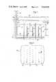
FIG. 1 is a vertical sectional view, partly diagrammatic, of a preferred embodiment of a system for the conductive heating of an earth formation in accordance with the present invention, wherein an array of electrodes is emplaced vertically, the section being taken transversely of the rows of electrodes;
FIG. 2 is a diagrammatic plan view of the system shown in FIG. 1;
FIG. 3 is an enlarged vertical sectional view, partly diagrammatic, of part of the system shown in FIG. 1;
FIG. 4 is a vertical sectional view, partly diagrammatic, of an alternative system for the conductive heating of an earth formation in accordance with the present invention, wherein an array of electrodes is emplaced horizontally, the section being taken longitudinally of the electrodes;
FIG. 5 is a vertical sectional view, partly diagrammatic of the system shown in FIG. 4, taken alongline 5--5 of FIG. 4;
FIG. 6 is a vertical sectional view comparable to that of FIG. 4 showing an alternative system with horizontal electrodes fed from both ends;
FIG. 7 is a plan view, mostly diagrammatic, of an alternative system comparable to that shown in FIG. 3, with cool walls adjacent electrodes;
FIG. 8 is a vertical sectional view, partly diagrammatic of the system shown in FIG. 7, taken along line 8--8 of FIG. 7;
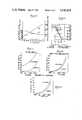
FIG. 9 is a set of curves showing the relationship between a time dependent factor c and heat loss and a function of deposit temperature utilizing the present invention;
FIG. 10 is a set of curves showing the temperature distribution at different heating rates when heat is delivered to a defined volume;
FIG. 11 is a set of curves showing the relationship between time and temperature at different points when a formation is heated by a sparse array;
FIG. 12 is a set of curves showing the relationship between time and temperature at different points when a formation is heated in accordance with the present invention with electrode diameters of 32 inches; and
FIG. 13 is a set of curves showing the relationship of time and temperature at the same points as in FIG. 12 in accordance with the present invention with electrode diameters of 14 inches.
FIGS. 1, 2 and 3 illustrate a system for heating conductive formations utilizing anarray 10 ofvertical electrodes electrodes 12 being grounded, and theelectrodes 14 being energized by a low frequency or d.c.source 16 of electrical power by means of acoaxial line 17. Theelectrodes electrode array 10 is a dense array, meaning that the spacing s between rows is greater than the distance d between electrodes in a row. The rows ofelectrodes 12 are longer than the rows ofelectrodes 14 to confine the electric fields and consequent heating at the ends of the rows ofelectrodes 14.
Theelectrodes respective boreholes 18. The electrodes may be emplaced from a mineddrift 20 accessed through ashaft 22 from thesurface 24 of the earth. Theelectrodes 12 preferably extend, as shown, through adeposit 26 or earth formation containing the hydrocarbons to be produced. Theelectrodes 12 extend into the overburden 28 above thedeposit 26 and into the underburden 30 below thedeposit 26. Theelectrodes 14, on the other hand, are shorter than theelectrodes 12 and extend only part way through thedeposit 26, short of the overburden 28 and underburden 30. In order to avoid heating the underburden and to provide the power connection, the lower portions of theelectrodes 14 may be insulated from the formations byinsulators 31, which may be air. The effective lengths of theelectrodes 14 therefore end at theinsulators 31, preferably spaced from the boundary of the deposit by at least 0.15 of the thickness of the deposit. The spacing s between rows of electrodes is preferably at least 0.6 of the thickness of the deposit.
FIGS. 4 and 5 illustrate a system for heating conductive formations utilizing anarray 32 ofhorizontal electrodes electrodes 34 being in the upper row and theelectrodes 36 in the lower row. Theupper electrodes 34 are preferably grounded, and thelower electrodes 36 are energized by a low frequency or d.c.source 38 of electrical power. Theelectrodes electrode array 32 is also a dense array. The upper row ofelectrodes 34 is longer than the lower row ofelectrodes 36 to confine the electric fields from theelectrodes 36. Theelectrodes 34 extend beyond both ends of theelectrodes 36 for the same reason. Grounding theupper electrodes 34 keeps down stray fields at thesurface 24 of the earth.
Theelectrodes respective boreholes 40 which may be drilled by well known directional drilling techniques to provide horizontal boreholes at the top and bottom of thedeposit 26 between theoverburden 28 and theunderburden 30. Preferably the upper boreholes are at the interface between thedeposit 26 and theoverburden 28, and the lower boreholes are slightly above the interface between thedeposit 26 and theunderburden 30.
FIG. 6 illustrates a system comparable to that shown in FIGS. 4 and 5 wherein the array is fed from both ends, asecond power source 42 being connected at the end remote from thepower source 38.
FIGS. 7 and 8 illustrate a system comparable to that of FIGS. 1, 2 and 3 with an array of vertical electrodes. In this system the rows oflike electrodes low field region 44 therebetween that is not directly heated to any great extent.
The deposit thickness h and the average or effective thermal diffusion properties determine the uniformity of the temperature distribution as a function of heating time t and can be generally described for any thickness of a deposit in the terms of a deposit temperature profile factor c, such that
c=kt/(h/2).sup.2
where k is the thermal diffusivity. FIG. 9 presents a curve A showing the relationship between the factor c and the portion of a deposit above 80% of the temperature rise of the center of the deposit for a uniform heating rate through the heated volume. Note that at c=0.1, about 75% of the heated volume has a temperature rise greater than 80% of the temperature rise of the center of the heated volume.
FIG. 10 illustrates the heating profiles for three values of the factor c as a function of the distance from the center of the heated volume, the fraction of the temperature rise that would have been reached in the heated volume in the absence of heat outflow. Note that where c=0.1 or c=0.2, the total percentage of heat lost to adjacent formations is relatively small, about 10% to 15%. Where low final temperatures, e.g., less than 100° C., are suitable, c up to 0.3 can be accepted, as the heat lost, or extra heat needed to maintain the final temperature, is, while significant, economically acceptable. FIG. 9, curve B, showing percent heat loss as a function of the factor c, shows percent heat loss to be less than 25% at c=0.3. On the other hand, if higher temperatures (e.g., about 200° C.) are desired to crack the bitumen, then higher central deposit temperatures above the design minimum are needed to process more of the deposit, especially if longer heating times are employed. Moreover, the heat outflows at these higher temperatures are more economically disadvantageous. Thus a temperature profile factor of c less than about 0.15 is required. In general the heating rate should be great enough that c is less than 30 times the inverse of the ultimate increase in temperature ΔT in degrees celsius of the volume:
c≦0.3(100/ΔT)
The lowest values of c are controlled more by the excess temperature of electrodes and are discussed below.
The electrode spacing distance d and diameter a are determined by the maximum allowable electrode temperature plus some excess if some local vaporization of the electrolyte and connate water can be tolerated. In a reasonably dense array, the hot regions around the electrodes are confined to the immediate vicinity of the electrodes. On the other hand, in a sparse array, where s is no greater than d, the excess heat zone comprises a major portion of the deposit.
FIG. 11 illustrates a grossly excessive heat build-up on the electrodes as compared to the center of the deposit for a sparse array. In this example row spacing s was 10 m, electrode spacing d 10 m, electrode diameter a 0.8 m, and thermal diffusivity 10-6 m2 /s, with no fluid flow.
FIG. 12 shows how the electrode temperature can be reduced by the use of a dense array. In this example row spacing s was 10 m, electrode spacing d 4 m, electrode diameter a 0.8 m, and thermal diffusivity 10-6 m2 /s, with no fluid flow.
FIG. 13 illustrates the effect of decreasing the diameter of the electrodes of the dense array of FIG. 12 such that the temperature of the electrode is increased somewhat more relative to the main deposit. In this example row spacing s was 10 m, electrode spacing d 4 m, electrode diameter a 0.35 m, and thermal diffusivity 10-6 m2 /s, with no fluid flow. The region of increased temperature is confined to the immediate vicinity of the electrode and does not constitute a major energy waste. Thus, varying the electrode separation distance d and the diameter of the electrode a permit controlling the temperature of the electrode either to prevent vaporization or excessive vaporization of the electrolyte in the borehole and connate water in the formations immediately adjacent the electrode.
The electrode spacing d and diameter a are chosen so that either electrode temperature is comparable to the vaporization temperature, or if some local vaporization is tolerable (as for a moderately dense array), the unmodified electrode temperature rise without vapor cooling will not significantly exceed the vaporization temperature.
The means for providing water for both vaporization and for maintenance of electrical conduction is shown in the drawings, particularly in FIG. 3 for vertical electrodes and in FIG. 4 for horizontal electrodes. As shown in FIG. 3, areservoir 46 of aqueous electrolyte provides a conductive solution that may be pumped by a flow regulator and pump 47 down theshaft 22 and up the interior of theelectrodes 12 and into the spaces between theelectrodes 12 and theformation 26. Avapor relief pipe 48, together with a pressure regulator and pump 50 returns excess electrolyte to thereservoir 46 and assures that the electrolyte always covers theelectrodes 12. Similarly, areservoir 52 provides such electrolyte down theshaft 22, whence it is driven by a pressure regulator and pump 53 up the interior of theelectrodes 14 and into the spaces between theelectrodes 14 and theformation 26. In this case the electrodes are energized and not at ground potential. Theconduits 54 carrying the electrolyte through theshaft 22 are therefore at the potential of the power supply and must be insulated from ground, as is thereservoir 52. Theconduits 54 are therefore in the central conductor of thecoaxial line 17. Theelectrodes 14 have correspondingvapor relief pipes 56 and a related pressure regulator and pump 58.
As shown in FIG. 4, electrolyte is provided as needed fromreservoirs 60, 61 to theinterior tubing 62 which also acts to connect thepower source 38 to therespective electrodes overburden 28 and thedeposit 26 by insulation 64. The electrolyte goes down thetubing 62 to keep the spaces between therespective electrodes deposit 26 full of conductive solution during heating. The tubing to thelower electrode 36 may later be used to pump out the oil entering the lower electrode, using apositive displacement pump 66.
In either system, the electrolyte acts as a heat sink to assure cool electrodes and maintain conductive paths between the respective electrodes and the deposit. The water in the electrolyte may boil and thereby absorb heat to cool the electrodes, as the water is replenished.
The vaporization temperature is controlled by the maximum sustainable pressure of the deposit. Typically for shallow to moderate depth deposits the gauge pressure can range from a few psig to 300 psig with a maximum of about 1300 psig for practical systems. The tightness of adjacent formations also influences the maximum sustainable vapor pressure. In some cases, injection of inert gases to assist in maintaining deposit pressure may be needed.
Another way to keep the electrodes cool is to position the electrodes adjacent a reduced field region on one side of an active electrode row. This reduces radically the heating rate in the region of the diminished field, thus creating in effect a heat sink which radically reduces the temperature of the electrodes, in the limiting case to about half the temperature rise of the center portion of the deposit.
As shown in FIGS. 7 and 8, in the case of vertical arrays, pairs ofelectrodes regions 44 between the pairs become low field regions. By proper selection of heating rates and pair separation, it is possible to control the temperature of the electrode at slightly below that for the center of the deposit. The thickness of thecool wall region 44 can be sufficiently thin that the cool wall region can achieve about 90% of the maximum deposit temperature via thermal diffusion from the heated volume after the application of power has ended.
As shown in FIGS. 4, 5 and 6 in the case of a nearly horizontally enlarged biplate, a zero field region exists on the barren side of the row of groundedupper electrodes 34 and a near zero field region exists on the barren side of the row of energizedelectrodes 36. Such low field regions act as theregions 44 in the system shown in FIGS. 7 and 8.
The arrangement of FIGS. 4, 5 and 6 with the upper electrodes grounded is superior to other arrangements of horizontal electrodes in respect to safety. No matter how the biplate rows are energized and grounded (such as upper electrode energized and lower electrode grounded, vice versa or both symmetrically driven in respect to ground) leakage currents will flow near thesurface 24 that may be small but significant in respect to safety and equipment protection. These currents will create field gradients which, although small, can be sufficient to develop hazardous potentials on surface or near-surface objects 68, such as pipelines, fences and other long metallic structures, or may destroy operation of above-ground electrical equipment. To mitigate such effects, ground mats can be employed near metallic structures to assure zero potential drops between any metallic structures likely to be touched by anyone.
These safety ground mats as well as electrical system grounds will collect the stray current from the biplate array. These grounds then serve in effect as additional ground electrodes of a line. Leakage currents between the grounding apparatus at the surface and the biplate array also heat the overburden, especially if the uppermost row is excited and the deposit is shallow. Thus biplate arrays, although having two sets of electrodes of large areal extent, also implictly contain a third but smaller set ofelectrodes 68 near the surface at ground protential. Although this third set of electrodes collects diminished currents, the design considerations previously discussed to prevent vaporization of water in the earth adjacent the other electrodes must also be applied.
The near surface ground currents are minimized if theupper electrodes 34 are grounded and thelower electrodes 36 are energized. Also the groundedupper electrodes 34 can be extended in length and width to provide added shielding. This requires placing product collection apparatus at the potential of the energized lower set of electrodes by means of isolation insulation. However, this arrangement reduces leakage energy losses as compared to other electrodes energizing arrangements. Such leakage currents tend to heat theoverburden 28 between the row ofupper electrodes 34 and the above-ground system 68, giving rise to unnecessary heat losses.
Short heating times stress the equipment, and therefore, the longest heating times consistent with reasonable heat losses are desirable. This is especially true for the horizontal biplate array. The conductors of an array in the biplate configuration, especially if it is fairly long, will inject or collect considerable current. The amount of current at the feed point will be proportional to the product of the conductor length l, the distance d between electrodes within the row, and the current density J needed to heat the deposit to the required temperature in time t. Thus the current I per conductor becomes at the feed point (assuming small attenuation along the line): ##EQU1## where σ is the conductivity of the reservoir and joules-to-heat is the energy required to heat a cubic meter to the desired temperature. Thus the current carrying requirement of the conductors at the feed points is reduced by increasing the heat up time t as determined by the maximum allowable temperature profile factor c and deposit thickness h. Further, making the array more dense, that is, decreasing d, also reduces the current carrying requirements as well as decreasing l. If conductor current at the feed point is excessive, heat will be generated in the electrode due to I2 R losses along the conductor. The power dissipated in the electrode due to I2 R losses can significantly exceed the power dissipated in the reservoir immediately adjacent the electrode. This can cause excessive heating of the electrode in addition to the excess heat generated in the adjacent formation due to the concentration of current near the electrode. Thus another criterion is that the I2 R conductor losses not be excessive compared to the power dissipated in the media due to narrowing of the current flow paths into the electrodes. Also the total collected current should not exceed the current carrying rating of the cable feed systems.
Another cause of excess temperature of the electrodes over that for the deposit arises from fringing fields near the sides of the row of excited electrodes. Here the outermost electrodes (in a direction transverse to the electrode axis) carry additional charges and currents associated with the fringing fields. As a consequence, both the adjacent reservoir dissipation and I2 R longitudinal conductor losses will be significantly increased over those experienced for electrodes more centrally located. To control the temperature of these outermost electrodes, several methods can be used, including: (1) increasing the density of the array in the outermost regions, (2) relying on additional vaporization to cool these electrodes, and (3) the enlarging the diameter of these electrodes. Some cooling benefit will also exist for the cool-wall approach, especially in the case of the vertical electrode arrays if an additional portion of the deposit can be included in the reduced field region near the outermost electrodes. Applying progressively smaller potentials as the outermost electrodes are neared is another option.
In the case of the biplate array, especially if it extends a great length into the deposit, such as over 100 m, special attention must be given to the path losses along the line. To alleviate the effects of such attenuation, the line may be fed from both ends, as shown in FIG. 6. At the higher frequencies, these are frequency dependent and are reduced as the frequency is decreased. Perhaps not appreciated in earlier work, is that there is a limit to how much the path attenuation can be reduced by lowering the frequency. The problem is aggravated because, as the deposit is heated, it becomes more conducting.
A buried biplate array or triplate array exhibits a path loss attenuation α of
α=8.7 [(R+jωL)(G+jωc)].sup.1/2 dB/m
where
R is the series resistance per meter of the buried line, which includes an added resistance contribution from skin effects in the conductor, if present,
L is the series inductance per meter of the buried line,
G is the shunt conductance over a meter for the line and is directly proportional to σ, the conductivity of the deposit,
C is the shunt capacitance over a meter for the line. Where conduction currents dominate, G>>jωC, so that the attenuation α becomes
α=8.7 [(R+jωL)(G)].sup.1/2 dB/m
If the frequency ω is reduced, jωL is radically reduced, R is partially decreased (owing to a reduction in skin effect loss contribution) and G tends to remain more or less constant. Eventually, as frequency ω is decreased, R>>jωL, usually at a near zero frequency condition, so that
α=8.7 [(R)(G)].sup.1/2 dB/m
If thin wall steel is used as the electrode material, unacceptable attenuation over a fairly long path lengths could occur, especially at the higher temperatures where conductance G and conductivity σ are greater. If thin walled copper or aluminum is used for electrodes (these may be clad with steel to resist corrosion), the near zero-frequency attenuation can be acceptably reduced so that
αl=8.7 [(R)(G)].sup.1/2 (l)≦2 dB
for the single end feed of FIG. 4 and less than 8 dB for the double end feed of FIG. 6.
When d.c. power is applied, advantage may be taken of electro-osmosis to promote the production of liquid hydrocarbons. In the case of electro-osmosis, water and accompanying oil drops are usually attracted to the negative electrodes. The factors affecting electro-osmosis are determined in part by the zeta potentials of the formation rock, and in some limited cases the zeta potentials may be such that water and oil are attracted to the positive potential electrodes.
While the use of electro-osmotic effects to enhance recovery from single wells or pairs of wells has been described, the employment of the dense array offers unique features heretofore unrecognized. For example, in the case of a pair of electrodes widely separated, the direct current emerges radially or spherically from the electrode. The radially divergent current produces a radially divergent electric field, and since the electro-osmotic effect is proportional to the electric field, the beneficial effects of electro-osmosis are evident only very near the electrode. Furthermore, the amount of current which can be introduced by an electrode is restricted by vaporization considerations or, if the deposit is pressurized, by a high temperature coking condition which may plug the producing capillary paths. On the other hand, with the arrangement of the present invention, the large electrode surface area and the controlled temperature below the vaporization point allows substantially more d.c. current to be introduced. Further, the effects of electro-osmosis are felt throughout the deposit, as uniform current flow and electric fields are established throughout the bulk of the deposit. Thus an electro-osmotic fluid drive phenomenon of substantial magnitude can be established throughout the deposit which can substantially enhance the production rates.
Further, electrolyte fluids will be drawn out of the electrodes which are not used to collect the water. Therefore, means to replace this electrolyte must be provided.
Although various preferred embodiments of the present invention have been described in some detail, various modifications may be made therein within the scope of the invention.
Several methods of production are possible beyond the unique features of electro-osmosis. Typically, the oil can be recovered via gravity or autogenously generated vapor drives into the perforated electrodes, which can serve as product collection paths. Provision for this type of product collection is illustrated in FIG. 4, where apositive displacement pump 66 located in the lowest level ofelectrode 36 can be used to recover the product. Product can be collected in some cases during the heat-up period. For example, in FIG. 4 the reservoir fluids will tend to collect in the lower electrode array. If those are produced during heating, those fluids can provide an additional or substitute means to control the temperature of the lower electrode. On the other hand, it may not be desirable to produce a deposit, if in situ cracking is planned, until the final temperature is reached.
Various "hybrid" production combinations may be considered to produce the deposit after heating. These could include fire-floods, steam floods and surfactant/polymer water floods. In these cases, one row of electrodes can be used for fluid injections and the adjacent row for fluid/product recovery.
The foregoing discussion, for simplicity, has limited consideration to either vertical or horizontal electrode arrays. However, arrays employed at an angle with respect to the deposit may be useful to minimize the number of drifts and the number of boreholes. In this case, the maximum row separation s is chosen to be midway between the vertical or horizontal situation, such that if largely vertical, the row separation s is not much greater than that found for the true vertical case. On the other hand, if the rows are nearly horizontal, then a value of s closer to that chosen for a horizontal array should be used.
Claims (12)
1. A method for the in situ heating of earth formations having substantial electrical conductivity, said method comprising
bounding a particular volume of a said earth formation with a waveguide structure formed of respective rows of discrete elongated electrodes in a dense array wherein the active electrode area and the row separation are chosen in reference to the formation thickness to avoid heating barren layers, and
applying electrical power at no more than a relatively low frequency between respective said rows of electrodes to deliver power to said formation while producing relatively uniform heating thereof and limiting the relative loss of heat to adjacent regions to less than a predetermined amount,
the electrode spacing and diameters limiting the temperature of said electrodes to near the vaporization point of water thereat to maintain an electrically conductive path between said electrodes and said formation.
2. A method for the in situ heating of earth formations having substantial electrical conductivity, said method comprising
bounding a particular volume of a said earth formation with a waveguide structure formed of respective rows of discrete elongated electrodes in a dense array wherein the active electrode area and the row separation are chosen in reference to the formation thickness to avoid heating barren layers,
applying electrical power at no more than a relatively low frequency between respective said rows of electrodes to deliver power to said formation while producing relatively uniform heating thereof and limiting the relative loss of heat to adjacent regions to less than a predetermined amount, and
at the same time controlling the temperature of said electrodes near the vaporization point of water thereat to maintain an electrically conductive path between said electrodes and said formation,
said power being applied to make the formation temperature profile factor c less than 30/ΔT, where ΔT is the increase in the temperature of the volume in degrees Celsius and
c=kt/(h/2).sup.2
where k is the mean thermal diffusivity of the formation, t is the heating time and h is the thickness of the formation.
3. A method for the in situ heating of earth formations having substantial electrical conductivity, said method comprising
bounding a particular volume of a said earth formation with a waveguide structure formed of respective rows of discrete elongated electrodes in a dense array wherein the active electrode area and the row separation are chosen in reference to the formation thickness to avoid heating barren layers,
applying electrical power at no more than a relatively low frequency between respective said rows of electrodes to deliver power to said formation while producing relatively uniform heating thereof and limiting the relative loss of heat to adjacent regions to less than a predetermined amount, and
at the same time controlling the temperature of said electrodes near the vaporization point of water thereat to maintain an electrically conductive path between said electrodes and said formation,
said electrodes being disposed transversely of said formation and the spacing between said rows being less than 0.6 of the thickness of said formation, said power being applied between said rows with one side of the power supply grounded, the grounded said electrodes being longer than said thickness, and the other said electrodes lying wholly within said formation by a least 0.15 of said thickness.
4. A method for the in situ heating of an earth formation having substantial electrical conductivity, said method comprising:
bounding a particular volume of said formation with a waveguide structure formed of respective rows of discrete elongated electrodes in a dense array wherein said electrodes are disposed parallel to and adjacent respective boundaries of said formation and the length and width of the active electrode area are large relative to the thickness of said formation to avoid heating barren layers, and said row of electrodes adjacent the upper boundary of said formation is grounded and extends over a greater area than the ungrounded electrodes to shield the region above the grounded electrodes from leakage fields,
applying electrical power at no more than a relatively low frequency between respective said rows of electrodes to substantially maximize the power delivered to said formation while producing relatively uniform heating thereof and thereby moderate the relative loss of heat to adjacent regions, and
at the same time controlling the temperature of said electrodes below the vaporization point of water thereat to maintain an electrically conductive path between said electrodes and said formation.
5. A method according to claim 4 further including grounded electrodes near the surface of the earth for collecting stray currents.
6. A method for the in situ heating of an earth formation having substantial electrical conductivity, said method comprising:
bounding a particular volume of said formation with a waveguide structure formed of respective rows of discrete elongated electrodes in a dense array wherein said electrodes are disposed parallel to and adjacent respective boundaries of said formation and the length and width of the active electrode area are large relative to the thickness of said formation to avoid heating barren layers,
applying electrical power at no more than a relatively low frequency between respective said rows of electrodes to substantially maximize the power delivered to said formation while producing relatively uniform heating thereof and thereby moderate the relative loss of heat to adjacent regions, wherein power attenuation along the electrodes with the power applied at one end is no greater than 2 dB, and
at the same time controlling the temperature of said electrodes below the vaporization point of water thereat to maintain an electrically conductive path between said electrodes and said formation.
7. A method for the in situ heating of an earth formation having substantial electrical conductivity, said method comprising:
bounding a particular volume of said formation with a waveguide structure formed of respective rows of discrete elongated electrodes in a dense array wherein said electrodes are disposed parallel to and adjacent respective boundaries of said formation and the length and width of the active electrode area are large relative to the thickness of said formation to avoid heating barren layers,
applying electrical power at no more than a relatively low frequency between respective said rows of electrodes to substantially maximize the power delivered to said formation while producing relatively uniform heating thereof and thereby moderate the relative loss of heat to adjacent regions, wherein power attenuation along the electrodes with the power applied substantially equally at both ends of the electrodes is less than 8 dB, and
at the same time controlling the temperature of said electrodes below the vaporization point of water thereat to maintain an electrically conductive path between said electrodes and said formation.
8. A method for the in situ heating of an earth formation having substantial electrical conductivity, said method comprising:
bounding a particular volume of said formation with a waveguide structure formed of respective rows of discrete elongated electrodes in a dense array wherein said electrodes are disposed parallel to and adjacent respective boundaries of said formation and the length and width of the active electrode area are large relative to the thickness of said formation to avoid heating barren layers,
applying electrical power at no more than a relatively low frequency between respective said rows of electrodes to substantially maximize the power delivered to said formation while producing relatively uniform heating thereof and thereby moderate the relative loss of heat to adjacent regions, wherein the diameter of the electrodes are sufficiently large and the array of such electrodes is so dense that the I2 R losses in the electrodes are small relative to the power dissipated in the formation adjacent the electrodes, and
at the same time controlling the temperature of said electrodes below the vaporization point of water thereat to maintain an electrically conductive path between said electrodes and said formation.
9. A method according to claim 8 wherein the density of the array is increased at the outermost electrodes.
10. A method according to claim 8 wherein the outermost electrodes are of larger diameter than the other electrodes.
11. A method for the in situ heating of earth formations having substantial electrical conductivity, said method comprising:
bounding a particular volume of a said earth formation with a waveguide structure formed of respective rows of discrete elongated electrodes in a dense array wherein the active electrode area and the row separation are chosen in reference to the formation thickness to avoid heating barren layers,
applying electrical power at no more than a relatively low frequency between respective said rows of electrodes to deliver power to said formation while producing relatively uniform heating thereof and limiting the relative loss of heat to adjacent regions to less than a predetermined amount, and
at the same time controlling the temperature of said electrodes near the vaporization point of water thereat to maintain an electrically conductive path between said electrodes and said formation,
said temperature of said electrodes being controlled by providing a heat sink adjacent said electrodes, said heat sink being provided by creating a region of reduced electric field intensity adjacent said rows of electrodes outside said bounded volume, and said region of reduced electric field being created by providing at least two adjacent rows of electrodes at the same potential spaced from each other by a wall sufficiently thick to cool the formation in the vicinity of the respective electrodes during the application of power and sufficiently thin to permit the wall to reach a desired operating temperature via thermal diffusion after the application of power has ended.
12. A method for the in situ heating of earth formations having substantial electrical conductivity, said method comprising
bounding a particular volume of a said earth formation with a waveguide structure formed of respective rows of discrete elongated electrodes in a dense array wherein the active electrode area and the row separation are chosen in reference to the formation thickness to avoid heating barren layers, and
applying electrical power at no more than a relatively low frequency for a limited period of time between respective said rows of electrodes to deliver power to said formation while producing relatively uniform heating thereof and limiting the relative loss of heat to adjacent regions to less than a predetermined amount,
at least two adjacent said rows of electrodes being at the same potential and spaced from each other by a wall sufficiently thick to provide thermal capacity for cooling the formation in the vicinity of the respective electrodes during the application of power and sufficiently thin as to be heated to a desired temperature via thermal diffusion after the application of power has ended.
Priority Applications (3)
| Application Number | Priority Date | Filing Date | Title |
|---|---|---|---|
| US06/489,849US4545435A (en) | 1983-04-29 | 1983-04-29 | Conduction heating of hydrocarbonaceous formations |
| AU27428/84AAU577283B2 (en) | 1983-04-29 | 1984-04-27 | Electro-osmotic production of hydrocarbons utilising conductive heating of hydrocarbonacedus formations |
| CA000452978ACA1209629A (en) | 1983-04-29 | 1984-04-27 | Conduction heating of hydrocarbonaceous formations |
Applications Claiming Priority (1)
| Application Number | Priority Date | Filing Date | Title |
|---|---|---|---|
| US06/489,849US4545435A (en) | 1983-04-29 | 1983-04-29 | Conduction heating of hydrocarbonaceous formations |
Publications (1)
| Publication Number | Publication Date |
|---|---|
| US4545435Atrue US4545435A (en) | 1985-10-08 |
Family
ID=23945521
Family Applications (1)
| Application Number | Title | Priority Date | Filing Date |
|---|---|---|---|
| US06/489,849Expired - Fee RelatedUS4545435A (en) | 1983-04-29 | 1983-04-29 | Conduction heating of hydrocarbonaceous formations |
Country Status (2)
| Country | Link |
|---|---|
| US (1) | US4545435A (en) |
| CA (1) | CA1209629A (en) |
Cited By (133)
| Publication number | Priority date | Publication date | Assignee | Title |
|---|---|---|---|---|
| US4645004A (en)* | 1983-04-29 | 1987-02-24 | Iit Research Institute | Electro-osmotic production of hydrocarbons utilizing conduction heating of hydrocarbonaceous formations |
| US4651825A (en)* | 1986-05-09 | 1987-03-24 | Atlantic Richfield Company | Enhanced well production |
| US4670634A (en)* | 1985-04-05 | 1987-06-02 | Iit Research Institute | In situ decontamination of spills and landfills by radio frequency heating |
| AU577283B2 (en)* | 1983-04-29 | 1988-09-22 | Iit Research Institute | Electro-osmotic production of hydrocarbons utilising conductive heating of hydrocarbonacedus formations |
| AU592268B2 (en)* | 1983-04-29 | 1990-01-04 | Iit Research Institute | Conduction heating of hydrocarbonaceous formations with electro-osmotic production of hydrocarbons |
| EP0317369A3 (en)* | 1987-11-20 | 1990-01-31 | Iit Research Institute | Confinement in porous material by driving out water and substituting sealant |
| US4926941A (en)* | 1989-10-10 | 1990-05-22 | Shell Oil Company | Method of producing tar sand deposits containing conductive layers |
| US4951748A (en)* | 1989-01-30 | 1990-08-28 | Gill William G | Technique for electrically heating formations |
| US4956535A (en)* | 1987-06-08 | 1990-09-11 | Battelle Memorial Institute | Electrode systems for in situ vitrification |
| US5042579A (en)* | 1990-08-23 | 1991-08-27 | Shell Oil Company | Method and apparatus for producing tar sand deposits containing conductive layers |
| US5046559A (en)* | 1990-08-23 | 1991-09-10 | Shell Oil Company | Method and apparatus for producing hydrocarbon bearing deposits in formations having shale layers |
| US5060726A (en)* | 1990-08-23 | 1991-10-29 | Shell Oil Company | Method and apparatus for producing tar sand deposits containing conductive layers having little or no vertical communication |
| US5065819A (en)* | 1990-03-09 | 1991-11-19 | Kai Technologies | Electromagnetic apparatus and method for in situ heating and recovery of organic and inorganic materials |
| US5082054A (en)* | 1990-02-12 | 1992-01-21 | Kiamanesh Anoosh I | In-situ tuned microwave oil extraction process |
| US5101899A (en)* | 1989-12-14 | 1992-04-07 | International Royal & Oil Company | Recovery of petroleum by electro-mechanical vibration |
| US5109927A (en)* | 1991-01-31 | 1992-05-05 | Supernaw Irwin R | RF in situ heating of heavy oil in combination with steam flooding |
| WO1992015770A1 (en)* | 1991-03-04 | 1992-09-17 | Kai Technologies, Inc. | Electromagnetic method and apparatus for the decontamination of hazardous material-containing volumes |
| US5167280A (en)* | 1990-06-24 | 1992-12-01 | Mobil Oil Corporation | Single horizontal well process for solvent/solute stimulation |
| US5318124A (en)* | 1991-11-14 | 1994-06-07 | Pecten International Company | Recovering hydrocarbons from tar sand or heavy oil reservoirs |
| US5339898A (en)* | 1993-07-13 | 1994-08-23 | Texaco Canada Petroleum, Inc. | Electromagnetic reservoir heating with vertical well supply and horizontal well return electrodes |
| US5420402A (en)* | 1992-02-05 | 1995-05-30 | Iit Research Institute | Methods and apparatus to confine earth currents for recovery of subsurface volatiles and semi-volatiles |
| US5487873A (en)* | 1990-03-30 | 1996-01-30 | Iit Research Institute | Method and apparatus for treating hazardous waste or other hydrocarbonaceous material |
| US5586213A (en)* | 1992-02-05 | 1996-12-17 | Iit Research Institute | Ionic contact media for electrodes and soil in conduction heating |
| US5656239A (en)* | 1989-10-27 | 1997-08-12 | Shell Oil Company | Method for recovering contaminants from soil utilizing electrical heating |
| US5664911A (en)* | 1991-05-03 | 1997-09-09 | Iit Research Institute | Method and apparatus for in situ decontamination of a site contaminated with a volatile material |
| US5829519A (en)* | 1997-03-10 | 1998-11-03 | Enhanced Energy, Inc. | Subterranean antenna cooling system |
| US5829528A (en)* | 1997-03-31 | 1998-11-03 | Enhanced Energy, Inc. | Ignition suppression system for down hole antennas |
| US5835866A (en)* | 1990-03-30 | 1998-11-10 | Iit Research Institute | Method for treating radioactive waste |
| US6199634B1 (en) | 1998-08-27 | 2001-03-13 | Viatchelav Ivanovich Selyakov | Method and apparatus for controlling the permeability of mineral bearing earth formations |
| US6328102B1 (en) | 1995-12-01 | 2001-12-11 | John C. Dean | Method and apparatus for piezoelectric transport |
| US6509557B1 (en)* | 1999-08-03 | 2003-01-21 | Shell Oil Company | Apparatus and method for heating single insulated flowlines |
| US6631761B2 (en)* | 2001-12-10 | 2003-10-14 | Alberta Science And Research Authority | Wet electric heating process |
| US20050024284A1 (en)* | 2003-07-14 | 2005-02-03 | Halek James Michael | Microwave demulsification of hydrocarbon emulsion |
| US20060110218A1 (en)* | 2004-11-23 | 2006-05-25 | Thermal Remediation Services | Electrode heating with remediation agent |
| WO2006116133A1 (en) | 2005-04-22 | 2006-11-02 | Shell Internationale Research Maatschappij B.V. | In situ conversion process systems utilizing wellbores in at least two regions of a formation |
| US20060289536A1 (en)* | 2004-04-23 | 2006-12-28 | Vinegar Harold J | Subsurface electrical heaters using nitride insulation |
| US20070187089A1 (en)* | 2006-01-19 | 2007-08-16 | Pyrophase, Inc. | Radio frequency technology heater for unconventional resources |
| US20070193744A1 (en)* | 2006-02-21 | 2007-08-23 | Pyrophase, Inc. | Electro thermal in situ energy storage for intermittent energy sources to recover fuel from hydro carbonaceous earth formations |
| US20080087428A1 (en)* | 2006-10-13 | 2008-04-17 | Exxonmobil Upstream Research Company | Enhanced shale oil production by in situ heating using hydraulically fractured producing wells |
| US20080087420A1 (en)* | 2006-10-13 | 2008-04-17 | Kaminsky Robert D | Optimized well spacing for in situ shale oil development |
| WO2008051834A3 (en)* | 2006-10-20 | 2008-08-07 | Shell Oil Co | Heating hydrocarbon containing formations in a spiral startup staged sequence |
| WO2008098850A1 (en)* | 2007-02-16 | 2008-08-21 | Siemens Aktiengesellschaft | Method and device for the in-situ extraction of a hydrocarbon-containing substance, while reducing the viscosity thereof, from an underground deposit |
| US7435037B2 (en) | 2005-04-22 | 2008-10-14 | Shell Oil Company | Low temperature barriers with heat interceptor wells for in situ processes |
| US7461691B2 (en) | 2001-10-24 | 2008-12-09 | Shell Oil Company | In situ recovery from a hydrocarbon containing formation |
| US7533719B2 (en) | 2006-04-21 | 2009-05-19 | Shell Oil Company | Wellhead with non-ferromagnetic materials |
| US7549470B2 (en) | 2005-10-24 | 2009-06-23 | Shell Oil Company | Solution mining and heating by oxidation for treating hydrocarbon containing formations |
| US20090283257A1 (en)* | 2008-05-18 | 2009-11-19 | Bj Services Company | Radio and microwave treatment of oil wells |
| US20090292571A1 (en)* | 2008-05-20 | 2009-11-26 | Osum Oil Sands Corp. | Method of managing carbon reduction for hydrocarbon producers |
| US7640987B2 (en) | 2005-08-17 | 2010-01-05 | Halliburton Energy Services, Inc. | Communicating fluids with a heated-fluid generation system |
| US7640980B2 (en) | 2003-04-24 | 2010-01-05 | Shell Oil Company | Thermal processes for subsurface formations |
| US20100058771A1 (en)* | 2008-07-07 | 2010-03-11 | Osum Oil Sands Corp. | Carbon removal from an integrated thermal recovery process |
| US20100147521A1 (en)* | 2008-10-13 | 2010-06-17 | Xueying Xie | Perforated electrical conductors for treating subsurface formations |
| US7770643B2 (en) | 2006-10-10 | 2010-08-10 | Halliburton Energy Services, Inc. | Hydrocarbon recovery using fluids |
| US7798220B2 (en) | 2007-04-20 | 2010-09-21 | Shell Oil Company | In situ heat treatment of a tar sands formation after drive process treatment |
| US7798221B2 (en) | 2000-04-24 | 2010-09-21 | Shell Oil Company | In situ recovery from a hydrocarbon containing formation |
| US20100243639A1 (en)* | 2009-03-24 | 2010-09-30 | Beyke Gregory L | Flexible horizontal electrode pipe |
| US7809538B2 (en) | 2006-01-13 | 2010-10-05 | Halliburton Energy Services, Inc. | Real time monitoring and control of thermal recovery operations for heavy oil reservoirs |
| US20100252249A1 (en)* | 2007-08-03 | 2010-10-07 | Dirk Diehl | Device for in situ extraction of a substance comprising hydrocarbons |
| US7832482B2 (en) | 2006-10-10 | 2010-11-16 | Halliburton Energy Services, Inc. | Producing resources using steam injection |
| US7866388B2 (en) | 2007-10-19 | 2011-01-11 | Shell Oil Company | High temperature methods for forming oxidizer fuel |
| US20110108273A1 (en)* | 2007-08-27 | 2011-05-12 | Norbert Huber | Method and apparatus for in situ extraction of bitumen or very heavy oil |
| US20110203792A1 (en)* | 2009-12-15 | 2011-08-25 | Chevron U.S.A. Inc. | System, method and assembly for wellbore maintenance operations |
| US8082995B2 (en) | 2007-12-10 | 2011-12-27 | Exxonmobil Upstream Research Company | Optimization of untreated oil shale geometry to control subsidence |
| US8087460B2 (en) | 2007-03-22 | 2012-01-03 | Exxonmobil Upstream Research Company | Granular electrical connections for in situ formation heating |
| US8104537B2 (en) | 2006-10-13 | 2012-01-31 | Exxonmobil Upstream Research Company | Method of developing subsurface freeze zone |
| US8122955B2 (en) | 2007-05-15 | 2012-02-28 | Exxonmobil Upstream Research Company | Downhole burners for in situ conversion of organic-rich rock formations |
| US8146664B2 (en) | 2007-05-25 | 2012-04-03 | Exxonmobil Upstream Research Company | Utilization of low BTU gas generated during in situ heating of organic-rich rock |
| US8151884B2 (en) | 2006-10-13 | 2012-04-10 | Exxonmobil Upstream Research Company | Combined development of oil shale by in situ heating with a deeper hydrocarbon resource |
| US8151877B2 (en) | 2007-05-15 | 2012-04-10 | Exxonmobil Upstream Research Company | Downhole burner wells for in situ conversion of organic-rich rock formations |
| US8151907B2 (en) | 2008-04-18 | 2012-04-10 | Shell Oil Company | Dual motor systems and non-rotating sensors for use in developing wellbores in subsurface formations |
| US8167960B2 (en) | 2007-10-22 | 2012-05-01 | Osum Oil Sands Corp. | Method of removing carbon dioxide emissions from in-situ recovery of bitumen and heavy oil |
| US8176982B2 (en) | 2008-02-06 | 2012-05-15 | Osum Oil Sands Corp. | Method of controlling a recovery and upgrading operation in a reservoir |
| US8224163B2 (en) | 2002-10-24 | 2012-07-17 | Shell Oil Company | Variable frequency temperature limited heaters |
| US8230929B2 (en) | 2008-05-23 | 2012-07-31 | Exxonmobil Upstream Research Company | Methods of producing hydrocarbons for substantially constant composition gas generation |
| US20120234537A1 (en)* | 2010-09-14 | 2012-09-20 | Harris Corporation | Gravity drainage startup using rf & solvent |
| US8327932B2 (en) | 2009-04-10 | 2012-12-11 | Shell Oil Company | Recovering energy from a subsurface formation |
| US8540020B2 (en) | 2009-05-05 | 2013-09-24 | Exxonmobil Upstream Research Company | Converting organic matter from a subterranean formation into producible hydrocarbons by controlling production operations based on availability of one or more production resources |
| US8608249B2 (en) | 2001-04-24 | 2013-12-17 | Shell Oil Company | In situ thermal processing of an oil shale formation |
| US8616279B2 (en) | 2009-02-23 | 2013-12-31 | Exxonmobil Upstream Research Company | Water treatment following shale oil production by in situ heating |
| US8616280B2 (en) | 2010-08-30 | 2013-12-31 | Exxonmobil Upstream Research Company | Wellbore mechanical integrity for in situ pyrolysis |
| US8622133B2 (en) | 2007-03-22 | 2014-01-07 | Exxonmobil Upstream Research Company | Resistive heater for in situ formation heating |
| US8622127B2 (en) | 2010-08-30 | 2014-01-07 | Exxonmobil Upstream Research Company | Olefin reduction for in situ pyrolysis oil generation |
| US8631866B2 (en) | 2010-04-09 | 2014-01-21 | Shell Oil Company | Leak detection in circulated fluid systems for heating subsurface formations |
| US8641150B2 (en) | 2006-04-21 | 2014-02-04 | Exxonmobil Upstream Research Company | In situ co-development of oil shale with mineral recovery |
| US8701769B2 (en) | 2010-04-09 | 2014-04-22 | Shell Oil Company | Methods for treating hydrocarbon formations based on geology |
| US8770284B2 (en) | 2012-05-04 | 2014-07-08 | Exxonmobil Upstream Research Company | Systems and methods of detecting an intersection between a wellbore and a subterranean structure that includes a marker material |
| US8820406B2 (en) | 2010-04-09 | 2014-09-02 | Shell Oil Company | Electrodes for electrical current flow heating of subsurface formations with conductive material in wellbore |
| US8863839B2 (en) | 2009-12-17 | 2014-10-21 | Exxonmobil Upstream Research Company | Enhanced convection for in situ pyrolysis of organic-rich rock formations |
| US8875789B2 (en) | 2007-05-25 | 2014-11-04 | Exxonmobil Upstream Research Company | Process for producing hydrocarbon fluids combining in situ heating, a power plant and a gas plant |
| US9016370B2 (en) | 2011-04-08 | 2015-04-28 | Shell Oil Company | Partial solution mining of hydrocarbon containing layers prior to in situ heat treatment |
| US9033042B2 (en) | 2010-04-09 | 2015-05-19 | Shell Oil Company | Forming bitumen barriers in subsurface hydrocarbon formations |
| US9080441B2 (en) | 2011-11-04 | 2015-07-14 | Exxonmobil Upstream Research Company | Multiple electrical connections to optimize heating for in situ pyrolysis |
| US9309755B2 (en) | 2011-10-07 | 2016-04-12 | Shell Oil Company | Thermal expansion accommodation for circulated fluid systems used to heat subsurface formations |
| US9394772B2 (en) | 2013-11-07 | 2016-07-19 | Exxonmobil Upstream Research Company | Systems and methods for in situ resistive heating of organic matter in a subterranean formation |
| US9512699B2 (en) | 2013-10-22 | 2016-12-06 | Exxonmobil Upstream Research Company | Systems and methods for regulating an in situ pyrolysis process |
| GB2539045A (en)* | 2015-06-05 | 2016-12-07 | Statoil Asa | Subsurface heater configuration for in situ hydrocarbon production |
| US9644466B2 (en) | 2014-11-21 | 2017-05-09 | Exxonmobil Upstream Research Company | Method of recovering hydrocarbons within a subsurface formation using electric current |
| US10047594B2 (en) | 2012-01-23 | 2018-08-14 | Genie Ip B.V. | Heater pattern for in situ thermal processing of a subsurface hydrocarbon containing formation |
| US10137486B1 (en)* | 2018-02-27 | 2018-11-27 | Chevron U.S.A. Inc. | Systems and methods for thermal treatment of contaminated material |
| US10487636B2 (en) | 2017-07-27 | 2019-11-26 | Exxonmobil Upstream Research Company | Enhanced methods for recovering viscous hydrocarbons from a subterranean formation as a follow-up to thermal recovery processes |
| US10641079B2 (en) | 2018-05-08 | 2020-05-05 | Saudi Arabian Oil Company | Solidifying filler material for well-integrity issues |
| US10697280B2 (en) | 2015-04-03 | 2020-06-30 | Rama Rau YELUNDUR | Apparatus and method of focused in-situ electrical heating of hydrocarbon bearing formations |
| US10941644B2 (en) | 2018-02-20 | 2021-03-09 | Saudi Arabian Oil Company | Downhole well integrity reconstruction in the hydrocarbon industry |
| US11002123B2 (en) | 2017-08-31 | 2021-05-11 | Exxonmobil Upstream Research Company | Thermal recovery methods for recovering viscous hydrocarbons from a subterranean formation |
| US11125075B1 (en) | 2020-03-25 | 2021-09-21 | Saudi Arabian Oil Company | Wellbore fluid level monitoring system |
| US11142681B2 (en) | 2017-06-29 | 2021-10-12 | Exxonmobil Upstream Research Company | Chasing solvent for enhanced recovery processes |
| US11149510B1 (en) | 2020-06-03 | 2021-10-19 | Saudi Arabian Oil Company | Freeing a stuck pipe from a wellbore |
| US11187068B2 (en) | 2019-01-31 | 2021-11-30 | Saudi Arabian Oil Company | Downhole tools for controlled fracture initiation and stimulation |
| US11255130B2 (en) | 2020-07-22 | 2022-02-22 | Saudi Arabian Oil Company | Sensing drill bit wear under downhole conditions |
| US11261725B2 (en) | 2017-10-24 | 2022-03-01 | Exxonmobil Upstream Research Company | Systems and methods for estimating and controlling liquid level using periodic shut-ins |
| US11280178B2 (en) | 2020-03-25 | 2022-03-22 | Saudi Arabian Oil Company | Wellbore fluid level monitoring system |
| US11391104B2 (en) | 2020-06-03 | 2022-07-19 | Saudi Arabian Oil Company | Freeing a stuck pipe from a wellbore |
| US11414985B2 (en) | 2020-05-28 | 2022-08-16 | Saudi Arabian Oil Company | Measuring wellbore cross-sections using downhole caliper tools |
| US11414963B2 (en) | 2020-03-25 | 2022-08-16 | Saudi Arabian Oil Company | Wellbore fluid level monitoring system |
| US11414984B2 (en) | 2020-05-28 | 2022-08-16 | Saudi Arabian Oil Company | Measuring wellbore cross-sections using downhole caliper tools |
| US11434714B2 (en) | 2021-01-04 | 2022-09-06 | Saudi Arabian Oil Company | Adjustable seal for sealing a fluid flow at a wellhead |
| US11506044B2 (en) | 2020-07-23 | 2022-11-22 | Saudi Arabian Oil Company | Automatic analysis of drill string dynamics |
| US11572752B2 (en) | 2021-02-24 | 2023-02-07 | Saudi Arabian Oil Company | Downhole cable deployment |
| US11619097B2 (en) | 2021-05-24 | 2023-04-04 | Saudi Arabian Oil Company | System and method for laser downhole extended sensing |
| US11624265B1 (en) | 2021-11-12 | 2023-04-11 | Saudi Arabian Oil Company | Cutting pipes in wellbores using downhole autonomous jet cutting tools |
| US11631884B2 (en) | 2020-06-02 | 2023-04-18 | Saudi Arabian Oil Company | Electrolyte structure for a high-temperature, high-pressure lithium battery |
| US11642709B1 (en) | 2021-03-04 | 2023-05-09 | Trs Group, Inc. | Optimized flux ERH electrode |
| US11697991B2 (en) | 2021-01-13 | 2023-07-11 | Saudi Arabian Oil Company | Rig sensor testing and calibration |
| US11719089B2 (en) | 2020-07-15 | 2023-08-08 | Saudi Arabian Oil Company | Analysis of drilling slurry solids by image processing |
| US11725504B2 (en) | 2021-05-24 | 2023-08-15 | Saudi Arabian Oil Company | Contactless real-time 3D mapping of surface equipment |
| US11727555B2 (en) | 2021-02-25 | 2023-08-15 | Saudi Arabian Oil Company | Rig power system efficiency optimization through image processing |
| US11739616B1 (en) | 2022-06-02 | 2023-08-29 | Saudi Arabian Oil Company | Forming perforation tunnels in a subterranean formation |
| US11846151B2 (en) | 2021-03-09 | 2023-12-19 | Saudi Arabian Oil Company | Repairing a cased wellbore |
| US11867008B2 (en) | 2020-11-05 | 2024-01-09 | Saudi Arabian Oil Company | System and methods for the measurement of drilling mud flow in real-time |
| US11867012B2 (en) | 2021-12-06 | 2024-01-09 | Saudi Arabian Oil Company | Gauge cutter and sampler apparatus |
| US11954800B2 (en) | 2021-12-14 | 2024-04-09 | Saudi Arabian Oil Company | Converting borehole images into three dimensional structures for numerical modeling and simulation applications |
| US11979950B2 (en) | 2020-02-18 | 2024-05-07 | Trs Group, Inc. | Heater for contaminant remediation |
| US12203366B2 (en) | 2023-05-02 | 2025-01-21 | Saudi Arabian Oil Company | Collecting samples from wellbores |
Families Citing this family (1)
| Publication number | Priority date | Publication date | Assignee | Title |
|---|---|---|---|---|
| NO20230232A1 (en)* | 2023-02-21 | 2024-08-22 | Tg & T As | CES Continuous Electrical Stimulation |
Citations (28)
| Publication number | Priority date | Publication date | Assignee | Title |
|---|---|---|---|---|
| US30738A (en)* | 1860-11-27 | Hot-air furnace | ||
| US2732195A (en)* | 1956-01-24 | Ljungstrom | ||
| US2795279A (en)* | 1952-04-17 | 1957-06-11 | Electrotherm Res Corp | Method of underground electrolinking and electrocarbonization of mineral fuels |
| US2799641A (en)* | 1955-04-29 | 1957-07-16 | John H Bruninga Sr | Electrolytically promoting the flow of oil from a well |
| US2801090A (en)* | 1956-04-02 | 1957-07-30 | Exxon Research Engineering Co | Sulfur mining using heating by electrolysis |
| US3137347A (en)* | 1960-05-09 | 1964-06-16 | Phillips Petroleum Co | In situ electrolinking of oil shale |
| US3428125A (en)* | 1966-07-25 | 1969-02-18 | Phillips Petroleum Co | Hydro-electropyrolysis of oil shale in situ |
| US3507330A (en)* | 1968-09-30 | 1970-04-21 | Electrothermic Co | Method and apparatus for secondary recovery of oil |
| US3547193A (en)* | 1969-10-08 | 1970-12-15 | Electrothermic Co | Method and apparatus for recovery of minerals from sub-surface formations using electricity |
| US3605888A (en)* | 1969-10-21 | 1971-09-20 | Electrothermic Co | Method and apparatus for secondary recovery of oil |
| US3620300A (en)* | 1970-04-20 | 1971-11-16 | Electrothermic Co | Method and apparatus for electrically heating a subsurface formation |
| US3642066A (en)* | 1969-11-13 | 1972-02-15 | Electrothermic Co | Electrical method and apparatus for the recovery of oil |
| US3724543A (en)* | 1971-03-03 | 1973-04-03 | Gen Electric | Electro-thermal process for production of off shore oil through on shore walls |
| US3782465A (en)* | 1971-11-09 | 1974-01-01 | Electro Petroleum | Electro-thermal process for promoting oil recovery |
| US3848671A (en)* | 1973-10-24 | 1974-11-19 | Atlantic Richfield Co | Method of producing bitumen from a subterranean tar sand formation |
| US3862662A (en)* | 1973-12-12 | 1975-01-28 | Atlantic Richfield Co | Method and apparatus for electrical heating of hydrocarbonaceous formations |
| US3874450A (en)* | 1973-12-12 | 1975-04-01 | Atlantic Richfield Co | Method and apparatus for electrically heating a subsurface formation |
| US3878312A (en)* | 1973-12-17 | 1975-04-15 | Gen Electric | Composite insulating barrier |
| US3946809A (en)* | 1974-12-19 | 1976-03-30 | Exxon Production Research Company | Oil recovery by combination steam stimulation and electrical heating |
| US3948319A (en)* | 1974-10-16 | 1976-04-06 | Atlantic Richfield Company | Method and apparatus for producing fluid by varying current flow through subterranean source formation |
| US3958636A (en)* | 1975-01-23 | 1976-05-25 | Atlantic Richfield Company | Production of bitumen from a tar sand formation |
| US4010799A (en)* | 1975-09-15 | 1977-03-08 | Petro-Canada Exploration Inc. | Method for reducing power loss associated with electrical heating of a subterranean formation |
| US4013538A (en)* | 1971-12-22 | 1977-03-22 | General Electric Company | Deep submersible power electrode assembly for ground conduction of electricity |
| US4084637A (en)* | 1976-12-16 | 1978-04-18 | Petro Canada Exploration Inc. | Method of producing viscous materials from subterranean formations |
| USRE30738E (en) | 1980-02-06 | 1981-09-08 | Iit Research Institute | Apparatus and method for in situ heat processing of hydrocarbonaceous formations |
| US4334580A (en)* | 1980-03-24 | 1982-06-15 | Geo Vann, Inc. | Continuous borehole formed horizontally through a hydrocarbon producing formation |
| US4382469A (en)* | 1981-03-10 | 1983-05-10 | Electro-Petroleum, Inc. | Method of in situ gasification |
| US4386665A (en)* | 1980-01-14 | 1983-06-07 | Mobil Oil Corporation | Drilling technique for providing multiple-pass penetration of a mineral-bearing formation |
- 1983
- 1983-04-29USUS06/489,849patent/US4545435A/ennot_activeExpired - Fee Related
- 1984
- 1984-04-27CACA000452978Apatent/CA1209629A/ennot_activeExpired
Patent Citations (28)
| Publication number | Priority date | Publication date | Assignee | Title |
|---|---|---|---|---|
| US30738A (en)* | 1860-11-27 | Hot-air furnace | ||
| US2732195A (en)* | 1956-01-24 | Ljungstrom | ||
| US2795279A (en)* | 1952-04-17 | 1957-06-11 | Electrotherm Res Corp | Method of underground electrolinking and electrocarbonization of mineral fuels |
| US2799641A (en)* | 1955-04-29 | 1957-07-16 | John H Bruninga Sr | Electrolytically promoting the flow of oil from a well |
| US2801090A (en)* | 1956-04-02 | 1957-07-30 | Exxon Research Engineering Co | Sulfur mining using heating by electrolysis |
| US3137347A (en)* | 1960-05-09 | 1964-06-16 | Phillips Petroleum Co | In situ electrolinking of oil shale |
| US3428125A (en)* | 1966-07-25 | 1969-02-18 | Phillips Petroleum Co | Hydro-electropyrolysis of oil shale in situ |
| US3507330A (en)* | 1968-09-30 | 1970-04-21 | Electrothermic Co | Method and apparatus for secondary recovery of oil |
| US3547193A (en)* | 1969-10-08 | 1970-12-15 | Electrothermic Co | Method and apparatus for recovery of minerals from sub-surface formations using electricity |
| US3605888A (en)* | 1969-10-21 | 1971-09-20 | Electrothermic Co | Method and apparatus for secondary recovery of oil |
| US3642066A (en)* | 1969-11-13 | 1972-02-15 | Electrothermic Co | Electrical method and apparatus for the recovery of oil |
| US3620300A (en)* | 1970-04-20 | 1971-11-16 | Electrothermic Co | Method and apparatus for electrically heating a subsurface formation |
| US3724543A (en)* | 1971-03-03 | 1973-04-03 | Gen Electric | Electro-thermal process for production of off shore oil through on shore walls |
| US3782465A (en)* | 1971-11-09 | 1974-01-01 | Electro Petroleum | Electro-thermal process for promoting oil recovery |
| US4013538A (en)* | 1971-12-22 | 1977-03-22 | General Electric Company | Deep submersible power electrode assembly for ground conduction of electricity |
| US3848671A (en)* | 1973-10-24 | 1974-11-19 | Atlantic Richfield Co | Method of producing bitumen from a subterranean tar sand formation |
| US3874450A (en)* | 1973-12-12 | 1975-04-01 | Atlantic Richfield Co | Method and apparatus for electrically heating a subsurface formation |
| US3862662A (en)* | 1973-12-12 | 1975-01-28 | Atlantic Richfield Co | Method and apparatus for electrical heating of hydrocarbonaceous formations |
| US3878312A (en)* | 1973-12-17 | 1975-04-15 | Gen Electric | Composite insulating barrier |
| US3948319A (en)* | 1974-10-16 | 1976-04-06 | Atlantic Richfield Company | Method and apparatus for producing fluid by varying current flow through subterranean source formation |
| US3946809A (en)* | 1974-12-19 | 1976-03-30 | Exxon Production Research Company | Oil recovery by combination steam stimulation and electrical heating |
| US3958636A (en)* | 1975-01-23 | 1976-05-25 | Atlantic Richfield Company | Production of bitumen from a tar sand formation |
| US4010799A (en)* | 1975-09-15 | 1977-03-08 | Petro-Canada Exploration Inc. | Method for reducing power loss associated with electrical heating of a subterranean formation |
| US4084637A (en)* | 1976-12-16 | 1978-04-18 | Petro Canada Exploration Inc. | Method of producing viscous materials from subterranean formations |
| US4386665A (en)* | 1980-01-14 | 1983-06-07 | Mobil Oil Corporation | Drilling technique for providing multiple-pass penetration of a mineral-bearing formation |
| USRE30738E (en) | 1980-02-06 | 1981-09-08 | Iit Research Institute | Apparatus and method for in situ heat processing of hydrocarbonaceous formations |
| US4334580A (en)* | 1980-03-24 | 1982-06-15 | Geo Vann, Inc. | Continuous borehole formed horizontally through a hydrocarbon producing formation |
| US4382469A (en)* | 1981-03-10 | 1983-05-10 | Electro-Petroleum, Inc. | Method of in situ gasification |
Non-Patent Citations (6)
| Title |
|---|
| Flock, Donald L., et al., "Unconventional Methods of Recovery of Bitumen and Related Research Areas Particular to the Oil Sands of Alberta," Journal of Canadian Petroleum Technology, Jul.-Sep., 1975, Montreal, pp. 17-20. |
| Flock, Donald L., et al., Unconventional Methods of Recovery of Bitumen and Related Research Areas Particular to the Oil Sands of Alberta, Journal of Canadian Petroleum Technology, Jul. Sep., 1975, Montreal, pp. 17 20.* |
| Harvey, A. Herbert, et al., "Selective Reservoir Heating Could Boost Oil Recovery," Oil & Gas Journal, Nov. 13, 1978, pp. 185-190. |
| Harvey, A. Herbert, et al., Selective Reservoir Heating Could Boost Oil Recovery, Oil & Gas Journal, Nov. 13, 1978, pp. 185 190.* |
| Vermeulen et al., "Physical Modelling of the Electromagnetic Heating of Oil Sand and Other Earth-Type and Biological Materials" Can. Elec. Eng. J., vol. 4, No. 4, 1979, pp. 19-28. |
| Vermeulen et al., Physical Modelling of the Electromagnetic Heating of Oil Sand and Other Earth Type and Biological Materials Can. Elec. Eng. J., vol. 4, No. 4, 1979, pp. 19 28.* |
Cited By (293)
| Publication number | Priority date | Publication date | Assignee | Title |
|---|---|---|---|---|
| US4645004A (en)* | 1983-04-29 | 1987-02-24 | Iit Research Institute | Electro-osmotic production of hydrocarbons utilizing conduction heating of hydrocarbonaceous formations |
| AU577283B2 (en)* | 1983-04-29 | 1988-09-22 | Iit Research Institute | Electro-osmotic production of hydrocarbons utilising conductive heating of hydrocarbonacedus formations |
| AU592268B2 (en)* | 1983-04-29 | 1990-01-04 | Iit Research Institute | Conduction heating of hydrocarbonaceous formations with electro-osmotic production of hydrocarbons |
| US4670634A (en)* | 1985-04-05 | 1987-06-02 | Iit Research Institute | In situ decontamination of spills and landfills by radio frequency heating |
| US4651825A (en)* | 1986-05-09 | 1987-03-24 | Atlantic Richfield Company | Enhanced well production |
| US4956535A (en)* | 1987-06-08 | 1990-09-11 | Battelle Memorial Institute | Electrode systems for in situ vitrification |
| EP0317369A3 (en)* | 1987-11-20 | 1990-01-31 | Iit Research Institute | Confinement in porous material by driving out water and substituting sealant |
| US4900196A (en)* | 1987-11-20 | 1990-02-13 | Iit Research Institute | Confinement in porous material by driving out water and substituting sealant |
| US4951748A (en)* | 1989-01-30 | 1990-08-28 | Gill William G | Technique for electrically heating formations |
| US4926941A (en)* | 1989-10-10 | 1990-05-22 | Shell Oil Company | Method of producing tar sand deposits containing conductive layers |
| US5656239A (en)* | 1989-10-27 | 1997-08-12 | Shell Oil Company | Method for recovering contaminants from soil utilizing electrical heating |
| US5101899A (en)* | 1989-12-14 | 1992-04-07 | International Royal & Oil Company | Recovery of petroleum by electro-mechanical vibration |
| US5082054A (en)* | 1990-02-12 | 1992-01-21 | Kiamanesh Anoosh I | In-situ tuned microwave oil extraction process |
| US5065819A (en)* | 1990-03-09 | 1991-11-19 | Kai Technologies | Electromagnetic apparatus and method for in situ heating and recovery of organic and inorganic materials |
| US5152341A (en)* | 1990-03-09 | 1992-10-06 | Raymond S. Kasevich | Electromagnetic method and apparatus for the decontamination of hazardous material-containing volumes |
| US5487873A (en)* | 1990-03-30 | 1996-01-30 | Iit Research Institute | Method and apparatus for treating hazardous waste or other hydrocarbonaceous material |
| US5835866A (en)* | 1990-03-30 | 1998-11-10 | Iit Research Institute | Method for treating radioactive waste |
| US5167280A (en)* | 1990-06-24 | 1992-12-01 | Mobil Oil Corporation | Single horizontal well process for solvent/solute stimulation |
| US5060726A (en)* | 1990-08-23 | 1991-10-29 | Shell Oil Company | Method and apparatus for producing tar sand deposits containing conductive layers having little or no vertical communication |
| US5046559A (en)* | 1990-08-23 | 1991-09-10 | Shell Oil Company | Method and apparatus for producing hydrocarbon bearing deposits in formations having shale layers |
| US5042579A (en)* | 1990-08-23 | 1991-08-27 | Shell Oil Company | Method and apparatus for producing tar sand deposits containing conductive layers |
| US5109927A (en)* | 1991-01-31 | 1992-05-05 | Supernaw Irwin R | RF in situ heating of heavy oil in combination with steam flooding |
| WO1992015770A1 (en)* | 1991-03-04 | 1992-09-17 | Kai Technologies, Inc. | Electromagnetic method and apparatus for the decontamination of hazardous material-containing volumes |
| US5664911A (en)* | 1991-05-03 | 1997-09-09 | Iit Research Institute | Method and apparatus for in situ decontamination of a site contaminated with a volatile material |
| US5318124A (en)* | 1991-11-14 | 1994-06-07 | Pecten International Company | Recovering hydrocarbons from tar sand or heavy oil reservoirs |
| US5621845A (en)* | 1992-02-05 | 1997-04-15 | Iit Research Institute | Apparatus for electrode heating of earth for recovery of subsurface volatiles and semi-volatiles |
| US5420402A (en)* | 1992-02-05 | 1995-05-30 | Iit Research Institute | Methods and apparatus to confine earth currents for recovery of subsurface volatiles and semi-volatiles |
| US5586213A (en)* | 1992-02-05 | 1996-12-17 | Iit Research Institute | Ionic contact media for electrodes and soil in conduction heating |
| US5339898A (en)* | 1993-07-13 | 1994-08-23 | Texaco Canada Petroleum, Inc. | Electromagnetic reservoir heating with vertical well supply and horizontal well return electrodes |
| US6328102B1 (en) | 1995-12-01 | 2001-12-11 | John C. Dean | Method and apparatus for piezoelectric transport |
| US5829519A (en)* | 1997-03-10 | 1998-11-03 | Enhanced Energy, Inc. | Subterranean antenna cooling system |
| US5829528A (en)* | 1997-03-31 | 1998-11-03 | Enhanced Energy, Inc. | Ignition suppression system for down hole antennas |
| US6199634B1 (en) | 1998-08-27 | 2001-03-13 | Viatchelav Ivanovich Selyakov | Method and apparatus for controlling the permeability of mineral bearing earth formations |
| US6509557B1 (en)* | 1999-08-03 | 2003-01-21 | Shell Oil Company | Apparatus and method for heating single insulated flowlines |
| US8485252B2 (en) | 2000-04-24 | 2013-07-16 | Shell Oil Company | In situ recovery from a hydrocarbon containing formation |
| US7798221B2 (en) | 2000-04-24 | 2010-09-21 | Shell Oil Company | In situ recovery from a hydrocarbon containing formation |
| US8789586B2 (en) | 2000-04-24 | 2014-07-29 | Shell Oil Company | In situ recovery from a hydrocarbon containing formation |
| US8225866B2 (en) | 2000-04-24 | 2012-07-24 | Shell Oil Company | In situ recovery from a hydrocarbon containing formation |
| US8608249B2 (en) | 2001-04-24 | 2013-12-17 | Shell Oil Company | In situ thermal processing of an oil shale formation |
| US20100126727A1 (en)* | 2001-10-24 | 2010-05-27 | Shell Oil Company | In situ recovery from a hydrocarbon containing formation |
| US20140190691A1 (en)* | 2001-10-24 | 2014-07-10 | Harold J. Vinegar | Method of selecting a production well location in a hydrocarbon subsurface formation |
| US7461691B2 (en) | 2001-10-24 | 2008-12-09 | Shell Oil Company | In situ recovery from a hydrocarbon containing formation |
| US8627887B2 (en)* | 2001-10-24 | 2014-01-14 | Shell Oil Company | In situ recovery from a hydrocarbon containing formation |
| US6631761B2 (en)* | 2001-12-10 | 2003-10-14 | Alberta Science And Research Authority | Wet electric heating process |
| US8224163B2 (en) | 2002-10-24 | 2012-07-17 | Shell Oil Company | Variable frequency temperature limited heaters |
| US8238730B2 (en) | 2002-10-24 | 2012-08-07 | Shell Oil Company | High voltage temperature limited heaters |
| US8224164B2 (en) | 2002-10-24 | 2012-07-17 | Shell Oil Company | Insulated conductor temperature limited heaters |
| US8579031B2 (en) | 2003-04-24 | 2013-11-12 | Shell Oil Company | Thermal processes for subsurface formations |
| US7942203B2 (en) | 2003-04-24 | 2011-05-17 | Shell Oil Company | Thermal processes for subsurface formations |
| US7640980B2 (en) | 2003-04-24 | 2010-01-05 | Shell Oil Company | Thermal processes for subsurface formations |
| US8596355B2 (en) | 2003-06-24 | 2013-12-03 | Exxonmobil Upstream Research Company | Optimized well spacing for in situ shale oil development |
| US7889146B2 (en) | 2003-07-14 | 2011-02-15 | Enhanced Energy, Inc. | Microwave demulsification of hydrocarbon emulsion |
| US20050024284A1 (en)* | 2003-07-14 | 2005-02-03 | Halek James Michael | Microwave demulsification of hydrocarbon emulsion |
| US7486248B2 (en) | 2003-07-14 | 2009-02-03 | Integrity Development, Inc. | Microwave demulsification of hydrocarbon emulsion |
| US7357180B2 (en) | 2004-04-23 | 2008-04-15 | Shell Oil Company | Inhibiting effects of sloughing in wellbores |
| US7383877B2 (en) | 2004-04-23 | 2008-06-10 | Shell Oil Company | Temperature limited heaters with thermally conductive fluid used to heat subsurface formations |
| US20060289536A1 (en)* | 2004-04-23 | 2006-12-28 | Vinegar Harold J | Subsurface electrical heaters using nitride insulation |
| US7490665B2 (en) | 2004-04-23 | 2009-02-17 | Shell Oil Company | Variable frequency temperature limited heaters |
| US7510000B2 (en) | 2004-04-23 | 2009-03-31 | Shell Oil Company | Reducing viscosity of oil for production from a hydrocarbon containing formation |
| US7320364B2 (en) | 2004-04-23 | 2008-01-22 | Shell Oil Company | Inhibiting reflux in a heated well of an in situ conversion system |
| US7431076B2 (en) | 2004-04-23 | 2008-10-07 | Shell Oil Company | Temperature limited heaters using modulated DC power |
| US7353872B2 (en) | 2004-04-23 | 2008-04-08 | Shell Oil Company | Start-up of temperature limited heaters using direct current (DC) |
| US7481274B2 (en) | 2004-04-23 | 2009-01-27 | Shell Oil Company | Temperature limited heaters with relatively constant current |
| US7424915B2 (en) | 2004-04-23 | 2008-09-16 | Shell Oil Company | Vacuum pumping of conductor-in-conduit heaters |
| US7370704B2 (en) | 2004-04-23 | 2008-05-13 | Shell Oil Company | Triaxial temperature limited heater |
| US20060110218A1 (en)* | 2004-11-23 | 2006-05-25 | Thermal Remediation Services | Electrode heating with remediation agent |
| US7290959B2 (en) | 2004-11-23 | 2007-11-06 | Thermal Remediation Services | Electrode heating with remediation agent |
| CN101163859B (en)* | 2005-04-22 | 2012-10-10 | 国际壳牌研究有限公司 | In situ conversion treatment system in at least two zones of the formation using a wellbore |
| US7831134B2 (en) | 2005-04-22 | 2010-11-09 | Shell Oil Company | Grouped exposed metal heaters |
| US8230927B2 (en) | 2005-04-22 | 2012-07-31 | Shell Oil Company | Methods and systems for producing fluid from an in situ conversion process |
| US8233782B2 (en) | 2005-04-22 | 2012-07-31 | Shell Oil Company | Grouped exposed metal heaters |
| US7546873B2 (en) | 2005-04-22 | 2009-06-16 | Shell Oil Company | Low temperature barriers for use with in situ processes |
| US7860377B2 (en) | 2005-04-22 | 2010-12-28 | Shell Oil Company | Subsurface connection methods for subsurface heaters |
| US7575052B2 (en) | 2005-04-22 | 2009-08-18 | Shell Oil Company | In situ conversion process utilizing a closed loop heating system |
| US7575053B2 (en) | 2005-04-22 | 2009-08-18 | Shell Oil Company | Low temperature monitoring system for subsurface barriers |
| US8224165B2 (en) | 2005-04-22 | 2012-07-17 | Shell Oil Company | Temperature limited heater utilizing non-ferromagnetic conductor |
| US8027571B2 (en) | 2005-04-22 | 2011-09-27 | Shell Oil Company | In situ conversion process systems utilizing wellbores in at least two regions of a formation |
| US7831133B2 (en) | 2005-04-22 | 2010-11-09 | Shell Oil Company | Insulated conductor temperature limited heater for subsurface heating coupled in a three-phase WYE configuration |
| EA014760B1 (en)* | 2005-04-22 | 2011-02-28 | Шелл Интернэшнл Рисерч Маатсхаппий Б.В. | System and method for heating subsurface formation |
| US7986869B2 (en) | 2005-04-22 | 2011-07-26 | Shell Oil Company | Varying properties along lengths of temperature limited heaters |
| US7942197B2 (en) | 2005-04-22 | 2011-05-17 | Shell Oil Company | Methods and systems for producing fluid from an in situ conversion process |
| US7527094B2 (en) | 2005-04-22 | 2009-05-05 | Shell Oil Company | Double barrier system for an in situ conversion process |
| US7500528B2 (en) | 2005-04-22 | 2009-03-10 | Shell Oil Company | Low temperature barrier wellbores formed using water flushing |
| US8070840B2 (en) | 2005-04-22 | 2011-12-06 | Shell Oil Company | Treatment of gas from an in situ conversion process |
| AU2006239999B2 (en)* | 2005-04-22 | 2010-06-17 | Shell Internationale Research Maatschappij B.V. | In situ conversion process systems utilizing wellbores in at least two regions of a formation |
| US7435037B2 (en) | 2005-04-22 | 2008-10-14 | Shell Oil Company | Low temperature barriers with heat interceptor wells for in situ processes |
| WO2006116133A1 (en) | 2005-04-22 | 2006-11-02 | Shell Internationale Research Maatschappij B.V. | In situ conversion process systems utilizing wellbores in at least two regions of a formation |
| US7640987B2 (en) | 2005-08-17 | 2010-01-05 | Halliburton Energy Services, Inc. | Communicating fluids with a heated-fluid generation system |
| US7584789B2 (en) | 2005-10-24 | 2009-09-08 | Shell Oil Company | Methods of cracking a crude product to produce additional crude products |
| US7549470B2 (en) | 2005-10-24 | 2009-06-23 | Shell Oil Company | Solution mining and heating by oxidation for treating hydrocarbon containing formations |
| US8151880B2 (en) | 2005-10-24 | 2012-04-10 | Shell Oil Company | Methods of making transportation fuel |
| US7556096B2 (en) | 2005-10-24 | 2009-07-07 | Shell Oil Company | Varying heating in dawsonite zones in hydrocarbon containing formations |
| US7581589B2 (en) | 2005-10-24 | 2009-09-01 | Shell Oil Company | Methods of producing alkylated hydrocarbons from an in situ heat treatment process liquid |
| US7562706B2 (en) | 2005-10-24 | 2009-07-21 | Shell Oil Company | Systems and methods for producing hydrocarbons from tar sands formations |
| US7559367B2 (en) | 2005-10-24 | 2009-07-14 | Shell Oil Company | Temperature limited heater with a conduit substantially electrically isolated from the formation |
| US7591310B2 (en) | 2005-10-24 | 2009-09-22 | Shell Oil Company | Methods of hydrotreating a liquid stream to remove clogging compounds |
| US7556095B2 (en) | 2005-10-24 | 2009-07-07 | Shell Oil Company | Solution mining dawsonite from hydrocarbon containing formations with a chelating agent |
| US7635025B2 (en) | 2005-10-24 | 2009-12-22 | Shell Oil Company | Cogeneration systems and processes for treating hydrocarbon containing formations |
| US7559368B2 (en) | 2005-10-24 | 2009-07-14 | Shell Oil Company | Solution mining systems and methods for treating hydrocarbon containing formations |
| US8606091B2 (en) | 2005-10-24 | 2013-12-10 | Shell Oil Company | Subsurface heaters with low sulfidation rates |
| US7809538B2 (en) | 2006-01-13 | 2010-10-05 | Halliburton Energy Services, Inc. | Real time monitoring and control of thermal recovery operations for heavy oil reservoirs |
| US8210256B2 (en) | 2006-01-19 | 2012-07-03 | Pyrophase, Inc. | Radio frequency technology heater for unconventional resources |
| US8408294B2 (en) | 2006-01-19 | 2013-04-02 | Pyrophase, Inc. | Radio frequency technology heater for unconventional resources |
| US20070187089A1 (en)* | 2006-01-19 | 2007-08-16 | Pyrophase, Inc. | Radio frequency technology heater for unconventional resources |
| US7484561B2 (en) | 2006-02-21 | 2009-02-03 | Pyrophase, Inc. | Electro thermal in situ energy storage for intermittent energy sources to recover fuel from hydro carbonaceous earth formations |
| US20070193744A1 (en)* | 2006-02-21 | 2007-08-23 | Pyrophase, Inc. | Electro thermal in situ energy storage for intermittent energy sources to recover fuel from hydro carbonaceous earth formations |
| US7683296B2 (en) | 2006-04-21 | 2010-03-23 | Shell Oil Company | Adjusting alloy compositions for selected properties in temperature limited heaters |
| US7604052B2 (en) | 2006-04-21 | 2009-10-20 | Shell Oil Company | Compositions produced using an in situ heat treatment process |
| US7673786B2 (en) | 2006-04-21 | 2010-03-09 | Shell Oil Company | Welding shield for coupling heaters |
| US7785427B2 (en) | 2006-04-21 | 2010-08-31 | Shell Oil Company | High strength alloys |
| US7631689B2 (en) | 2006-04-21 | 2009-12-15 | Shell Oil Company | Sulfur barrier for use with in situ processes for treating formations |
| US8857506B2 (en) | 2006-04-21 | 2014-10-14 | Shell Oil Company | Alternate energy source usage methods for in situ heat treatment processes |
| US7610962B2 (en) | 2006-04-21 | 2009-11-03 | Shell Oil Company | Sour gas injection for use with in situ heat treatment |
| US7912358B2 (en) | 2006-04-21 | 2011-03-22 | Shell Oil Company | Alternate energy source usage for in situ heat treatment processes |
| US7533719B2 (en) | 2006-04-21 | 2009-05-19 | Shell Oil Company | Wellhead with non-ferromagnetic materials |
| US8641150B2 (en) | 2006-04-21 | 2014-02-04 | Exxonmobil Upstream Research Company | In situ co-development of oil shale with mineral recovery |
| US7597147B2 (en) | 2006-04-21 | 2009-10-06 | Shell Oil Company | Temperature limited heaters using phase transformation of ferromagnetic material |
| US8083813B2 (en) | 2006-04-21 | 2011-12-27 | Shell Oil Company | Methods of producing transportation fuel |
| US7635023B2 (en) | 2006-04-21 | 2009-12-22 | Shell Oil Company | Time sequenced heating of multiple layers in a hydrocarbon containing formation |
| US8192682B2 (en) | 2006-04-21 | 2012-06-05 | Shell Oil Company | High strength alloys |
| US7866385B2 (en) | 2006-04-21 | 2011-01-11 | Shell Oil Company | Power systems utilizing the heat of produced formation fluid |
| US7832482B2 (en) | 2006-10-10 | 2010-11-16 | Halliburton Energy Services, Inc. | Producing resources using steam injection |
| US7770643B2 (en) | 2006-10-10 | 2010-08-10 | Halliburton Energy Services, Inc. | Hydrocarbon recovery using fluids |
| US8151884B2 (en) | 2006-10-13 | 2012-04-10 | Exxonmobil Upstream Research Company | Combined development of oil shale by in situ heating with a deeper hydrocarbon resource |
| US20080087420A1 (en)* | 2006-10-13 | 2008-04-17 | Kaminsky Robert D | Optimized well spacing for in situ shale oil development |
| US8104537B2 (en) | 2006-10-13 | 2012-01-31 | Exxonmobil Upstream Research Company | Method of developing subsurface freeze zone |
| US7669657B2 (en) | 2006-10-13 | 2010-03-02 | Exxonmobil Upstream Research Company | Enhanced shale oil production by in situ heating using hydraulically fractured producing wells |
| US20080087428A1 (en)* | 2006-10-13 | 2008-04-17 | Exxonmobil Upstream Research Company | Enhanced shale oil production by in situ heating using hydraulically fractured producing wells |
| US7703513B2 (en) | 2006-10-20 | 2010-04-27 | Shell Oil Company | Wax barrier for use with in situ processes for treating formations |
| US7677314B2 (en) | 2006-10-20 | 2010-03-16 | Shell Oil Company | Method of condensing vaporized water in situ to treat tar sands formations |
| US7631690B2 (en) | 2006-10-20 | 2009-12-15 | Shell Oil Company | Heating hydrocarbon containing formations in a spiral startup staged sequence |
| GB2456251B (en)* | 2006-10-20 | 2011-03-16 | Shell Int Research | Heating hydrocarbon containing formations in a spiral startup staged sequence |
| US7730947B2 (en) | 2006-10-20 | 2010-06-08 | Shell Oil Company | Creating fluid injectivity in tar sands formations |
| US7730945B2 (en) | 2006-10-20 | 2010-06-08 | Shell Oil Company | Using geothermal energy to heat a portion of a formation for an in situ heat treatment process |
| US7730946B2 (en) | 2006-10-20 | 2010-06-08 | Shell Oil Company | Treating tar sands formations with dolomite |
| US7717171B2 (en) | 2006-10-20 | 2010-05-18 | Shell Oil Company | Moving hydrocarbons through portions of tar sands formations with a fluid |
| US7540324B2 (en) | 2006-10-20 | 2009-06-02 | Shell Oil Company | Heating hydrocarbon containing formations in a checkerboard pattern staged process |
| US7644765B2 (en) | 2006-10-20 | 2010-01-12 | Shell Oil Company | Heating tar sands formations while controlling pressure |
| US7845411B2 (en) | 2006-10-20 | 2010-12-07 | Shell Oil Company | In situ heat treatment process utilizing a closed loop heating system |
| US8191630B2 (en) | 2006-10-20 | 2012-06-05 | Shell Oil Company | Creating fluid injectivity in tar sands formations |
| WO2008051834A3 (en)* | 2006-10-20 | 2008-08-07 | Shell Oil Co | Heating hydrocarbon containing formations in a spiral startup staged sequence |
| GB2456251A (en)* | 2006-10-20 | 2009-07-15 | Shell Int Research | Heating hydrocarbon containing formations in a spiral startup staged sequence |
| US7841401B2 (en) | 2006-10-20 | 2010-11-30 | Shell Oil Company | Gas injection to inhibit migration during an in situ heat treatment process |
| US7681647B2 (en) | 2006-10-20 | 2010-03-23 | Shell Oil Company | Method of producing drive fluid in situ in tar sands formations |
| US7635024B2 (en) | 2006-10-20 | 2009-12-22 | Shell Oil Company | Heating tar sands formations to visbreaking temperatures |
| US7677310B2 (en) | 2006-10-20 | 2010-03-16 | Shell Oil Company | Creating and maintaining a gas cap in tar sands formations |
| US7673681B2 (en) | 2006-10-20 | 2010-03-09 | Shell Oil Company | Treating tar sands formations with karsted zones |
| US7562707B2 (en) | 2006-10-20 | 2009-07-21 | Shell Oil Company | Heating hydrocarbon containing formations in a line drive staged process |
| US8555971B2 (en) | 2006-10-20 | 2013-10-15 | Shell Oil Company | Treating tar sands formations with dolomite |
| US8091632B2 (en) | 2007-02-16 | 2012-01-10 | Siemens Aktiengesellschaft | Method and device for the in-situ extraction of a hydrocarbon-containing substance from an underground deposit |
| WO2008098850A1 (en)* | 2007-02-16 | 2008-08-21 | Siemens Aktiengesellschaft | Method and device for the in-situ extraction of a hydrocarbon-containing substance, while reducing the viscosity thereof, from an underground deposit |
| US20100108318A1 (en)* | 2007-02-16 | 2010-05-06 | Dirk Diehl | Method and device for the in-situ extraction of a hydrocarbon-containing substance, while reducing the viscosity thereof, from an underground deposit |
| US8087460B2 (en) | 2007-03-22 | 2012-01-03 | Exxonmobil Upstream Research Company | Granular electrical connections for in situ formation heating |
| US8622133B2 (en) | 2007-03-22 | 2014-01-07 | Exxonmobil Upstream Research Company | Resistive heater for in situ formation heating |
| US9347302B2 (en) | 2007-03-22 | 2016-05-24 | Exxonmobil Upstream Research Company | Resistive heater for in situ formation heating |
| US8662175B2 (en) | 2007-04-20 | 2014-03-04 | Shell Oil Company | Varying properties of in situ heat treatment of a tar sands formation based on assessed viscosities |
| US7832484B2 (en) | 2007-04-20 | 2010-11-16 | Shell Oil Company | Molten salt as a heat transfer fluid for heating a subsurface formation |
| US9181780B2 (en) | 2007-04-20 | 2015-11-10 | Shell Oil Company | Controlling and assessing pressure conditions during treatment of tar sands formations |
| US7841408B2 (en) | 2007-04-20 | 2010-11-30 | Shell Oil Company | In situ heat treatment from multiple layers of a tar sands formation |
| US8459359B2 (en) | 2007-04-20 | 2013-06-11 | Shell Oil Company | Treating nahcolite containing formations and saline zones |
| US7849922B2 (en) | 2007-04-20 | 2010-12-14 | Shell Oil Company | In situ recovery from residually heated sections in a hydrocarbon containing formation |
| US8381815B2 (en) | 2007-04-20 | 2013-02-26 | Shell Oil Company | Production from multiple zones of a tar sands formation |
| US8042610B2 (en) | 2007-04-20 | 2011-10-25 | Shell Oil Company | Parallel heater system for subsurface formations |
| US7798220B2 (en) | 2007-04-20 | 2010-09-21 | Shell Oil Company | In situ heat treatment of a tar sands formation after drive process treatment |
| US8327681B2 (en) | 2007-04-20 | 2012-12-11 | Shell Oil Company | Wellbore manufacturing processes for in situ heat treatment processes |
| US7841425B2 (en) | 2007-04-20 | 2010-11-30 | Shell Oil Company | Drilling subsurface wellbores with cutting structures |
| US8791396B2 (en) | 2007-04-20 | 2014-07-29 | Shell Oil Company | Floating insulated conductors for heating subsurface formations |
| US7931086B2 (en) | 2007-04-20 | 2011-04-26 | Shell Oil Company | Heating systems for heating subsurface formations |
| US7950453B2 (en) | 2007-04-20 | 2011-05-31 | Shell Oil Company | Downhole burner systems and methods for heating subsurface formations |
| US8122955B2 (en) | 2007-05-15 | 2012-02-28 | Exxonmobil Upstream Research Company | Downhole burners for in situ conversion of organic-rich rock formations |
| US8151877B2 (en) | 2007-05-15 | 2012-04-10 | Exxonmobil Upstream Research Company | Downhole burner wells for in situ conversion of organic-rich rock formations |
| US8875789B2 (en) | 2007-05-25 | 2014-11-04 | Exxonmobil Upstream Research Company | Process for producing hydrocarbon fluids combining in situ heating, a power plant and a gas plant |
| US8146664B2 (en) | 2007-05-25 | 2012-04-03 | Exxonmobil Upstream Research Company | Utilization of low BTU gas generated during in situ heating of organic-rich rock |
| RU2426868C1 (en)* | 2007-08-03 | 2011-08-20 | Сименс Акциенгезелльшафт | Device for extraction of hydrocarbon containing substance in places of natural bedding |
| WO2009019197A3 (en)* | 2007-08-03 | 2010-10-21 | Siemens Aktiengesellschaft | Device for in situ extraction of a substance comprising hydrocarbons |
| US20100252249A1 (en)* | 2007-08-03 | 2010-10-07 | Dirk Diehl | Device for in situ extraction of a substance comprising hydrocarbons |
| US8485254B2 (en)* | 2007-08-27 | 2013-07-16 | Siemens Aktiengesellschaft | Method and apparatus for in situ extraction of bitumen or very heavy oil |
| US20110108273A1 (en)* | 2007-08-27 | 2011-05-12 | Norbert Huber | Method and apparatus for in situ extraction of bitumen or very heavy oil |
| US8276661B2 (en) | 2007-10-19 | 2012-10-02 | Shell Oil Company | Heating subsurface formations by oxidizing fuel on a fuel carrier |
| US8272455B2 (en) | 2007-10-19 | 2012-09-25 | Shell Oil Company | Methods for forming wellbores in heated formations |
| US8146669B2 (en) | 2007-10-19 | 2012-04-03 | Shell Oil Company | Multi-step heater deployment in a subsurface formation |
| US8196658B2 (en) | 2007-10-19 | 2012-06-12 | Shell Oil Company | Irregular spacing of heat sources for treating hydrocarbon containing formations |
| US7866386B2 (en) | 2007-10-19 | 2011-01-11 | Shell Oil Company | In situ oxidation of subsurface formations |
| US8146661B2 (en) | 2007-10-19 | 2012-04-03 | Shell Oil Company | Cryogenic treatment of gas |
| US8113272B2 (en) | 2007-10-19 | 2012-02-14 | Shell Oil Company | Three-phase heaters with common overburden sections for heating subsurface formations |
| US8162059B2 (en) | 2007-10-19 | 2012-04-24 | Shell Oil Company | Induction heaters used to heat subsurface formations |
| US8011451B2 (en) | 2007-10-19 | 2011-09-06 | Shell Oil Company | Ranging methods for developing wellbores in subsurface formations |
| US8536497B2 (en) | 2007-10-19 | 2013-09-17 | Shell Oil Company | Methods for forming long subsurface heaters |
| US7866388B2 (en) | 2007-10-19 | 2011-01-11 | Shell Oil Company | High temperature methods for forming oxidizer fuel |
| US8240774B2 (en) | 2007-10-19 | 2012-08-14 | Shell Oil Company | Solution mining and in situ treatment of nahcolite beds |
| US8167960B2 (en) | 2007-10-22 | 2012-05-01 | Osum Oil Sands Corp. | Method of removing carbon dioxide emissions from in-situ recovery of bitumen and heavy oil |
| US8082995B2 (en) | 2007-12-10 | 2011-12-27 | Exxonmobil Upstream Research Company | Optimization of untreated oil shale geometry to control subsidence |
| US8176982B2 (en) | 2008-02-06 | 2012-05-15 | Osum Oil Sands Corp. | Method of controlling a recovery and upgrading operation in a reservoir |
| US8177305B2 (en) | 2008-04-18 | 2012-05-15 | Shell Oil Company | Heater connections in mines and tunnels for use in treating subsurface hydrocarbon containing formations |
| US8562078B2 (en) | 2008-04-18 | 2013-10-22 | Shell Oil Company | Hydrocarbon production from mines and tunnels used in treating subsurface hydrocarbon containing formations |
| US8172335B2 (en) | 2008-04-18 | 2012-05-08 | Shell Oil Company | Electrical current flow between tunnels for use in heating subsurface hydrocarbon containing formations |
| US8162405B2 (en) | 2008-04-18 | 2012-04-24 | Shell Oil Company | Using tunnels for treating subsurface hydrocarbon containing formations |
| US9528322B2 (en) | 2008-04-18 | 2016-12-27 | Shell Oil Company | Dual motor systems and non-rotating sensors for use in developing wellbores in subsurface formations |
| US8151907B2 (en) | 2008-04-18 | 2012-04-10 | Shell Oil Company | Dual motor systems and non-rotating sensors for use in developing wellbores in subsurface formations |
| US8636323B2 (en) | 2008-04-18 | 2014-01-28 | Shell Oil Company | Mines and tunnels for use in treating subsurface hydrocarbon containing formations |
| US8752904B2 (en) | 2008-04-18 | 2014-06-17 | Shell Oil Company | Heated fluid flow in mines and tunnels used in heating subsurface hydrocarbon containing formations |
| US20090283257A1 (en)* | 2008-05-18 | 2009-11-19 | Bj Services Company | Radio and microwave treatment of oil wells |
| US20090292571A1 (en)* | 2008-05-20 | 2009-11-26 | Osum Oil Sands Corp. | Method of managing carbon reduction for hydrocarbon producers |
| US8209192B2 (en) | 2008-05-20 | 2012-06-26 | Osum Oil Sands Corp. | Method of managing carbon reduction for hydrocarbon producers |
| US8230929B2 (en) | 2008-05-23 | 2012-07-31 | Exxonmobil Upstream Research Company | Methods of producing hydrocarbons for substantially constant composition gas generation |
| US20100058771A1 (en)* | 2008-07-07 | 2010-03-11 | Osum Oil Sands Corp. | Carbon removal from an integrated thermal recovery process |
| US9051829B2 (en)* | 2008-10-13 | 2015-06-09 | Shell Oil Company | Perforated electrical conductors for treating subsurface formations |
| US8267170B2 (en) | 2008-10-13 | 2012-09-18 | Shell Oil Company | Offset barrier wells in subsurface formations |
| US8261832B2 (en) | 2008-10-13 | 2012-09-11 | Shell Oil Company | Heating subsurface formations with fluids |
| US8353347B2 (en) | 2008-10-13 | 2013-01-15 | Shell Oil Company | Deployment of insulated conductors for treating subsurface formations |
| US8256512B2 (en) | 2008-10-13 | 2012-09-04 | Shell Oil Company | Movable heaters for treating subsurface hydrocarbon containing formations |
| US8881806B2 (en) | 2008-10-13 | 2014-11-11 | Shell Oil Company | Systems and methods for treating a subsurface formation with electrical conductors |
| US8220539B2 (en) | 2008-10-13 | 2012-07-17 | Shell Oil Company | Controlling hydrogen pressure in self-regulating nuclear reactors used to treat a subsurface formation |
| US8281861B2 (en) | 2008-10-13 | 2012-10-09 | Shell Oil Company | Circulated heated transfer fluid heating of subsurface hydrocarbon formations |
| US20100147521A1 (en)* | 2008-10-13 | 2010-06-17 | Xueying Xie | Perforated electrical conductors for treating subsurface formations |
| US9129728B2 (en) | 2008-10-13 | 2015-09-08 | Shell Oil Company | Systems and methods of forming subsurface wellbores |
| US8267185B2 (en) | 2008-10-13 | 2012-09-18 | Shell Oil Company | Circulated heated transfer fluid systems used to treat a subsurface formation |
| US9022118B2 (en) | 2008-10-13 | 2015-05-05 | Shell Oil Company | Double insulated heaters for treating subsurface formations |
| US8616279B2 (en) | 2009-02-23 | 2013-12-31 | Exxonmobil Upstream Research Company | Water treatment following shale oil production by in situ heating |
| US20100243639A1 (en)* | 2009-03-24 | 2010-09-30 | Beyke Gregory L | Flexible horizontal electrode pipe |
| US8448707B2 (en) | 2009-04-10 | 2013-05-28 | Shell Oil Company | Non-conducting heater casings |
| US8327932B2 (en) | 2009-04-10 | 2012-12-11 | Shell Oil Company | Recovering energy from a subsurface formation |
| US8434555B2 (en) | 2009-04-10 | 2013-05-07 | Shell Oil Company | Irregular pattern treatment of a subsurface formation |
| US8851170B2 (en) | 2009-04-10 | 2014-10-07 | Shell Oil Company | Heater assisted fluid treatment of a subsurface formation |
| US8540020B2 (en) | 2009-05-05 | 2013-09-24 | Exxonmobil Upstream Research Company | Converting organic matter from a subterranean formation into producible hydrocarbons by controlling production operations based on availability of one or more production resources |
| US20110203792A1 (en)* | 2009-12-15 | 2011-08-25 | Chevron U.S.A. Inc. | System, method and assembly for wellbore maintenance operations |
| US8863839B2 (en) | 2009-12-17 | 2014-10-21 | Exxonmobil Upstream Research Company | Enhanced convection for in situ pyrolysis of organic-rich rock formations |
| US8701768B2 (en) | 2010-04-09 | 2014-04-22 | Shell Oil Company | Methods for treating hydrocarbon formations |
| US9127538B2 (en) | 2010-04-09 | 2015-09-08 | Shell Oil Company | Methodologies for treatment of hydrocarbon formations using staged pyrolyzation |
| US8820406B2 (en) | 2010-04-09 | 2014-09-02 | Shell Oil Company | Electrodes for electrical current flow heating of subsurface formations with conductive material in wellbore |
| US9399905B2 (en) | 2010-04-09 | 2016-07-26 | Shell Oil Company | Leak detection in circulated fluid systems for heating subsurface formations |
| US8631866B2 (en) | 2010-04-09 | 2014-01-21 | Shell Oil Company | Leak detection in circulated fluid systems for heating subsurface formations |
| US8833453B2 (en) | 2010-04-09 | 2014-09-16 | Shell Oil Company | Electrodes for electrical current flow heating of subsurface formations with tapered copper thickness |
| US9022109B2 (en) | 2010-04-09 | 2015-05-05 | Shell Oil Company | Leak detection in circulated fluid systems for heating subsurface formations |
| US8739874B2 (en) | 2010-04-09 | 2014-06-03 | Shell Oil Company | Methods for heating with slots in hydrocarbon formations |
| US9033042B2 (en) | 2010-04-09 | 2015-05-19 | Shell Oil Company | Forming bitumen barriers in subsurface hydrocarbon formations |
| US8701769B2 (en) | 2010-04-09 | 2014-04-22 | Shell Oil Company | Methods for treating hydrocarbon formations based on geology |
| US9127523B2 (en) | 2010-04-09 | 2015-09-08 | Shell Oil Company | Barrier methods for use in subsurface hydrocarbon formations |
| US8622127B2 (en) | 2010-08-30 | 2014-01-07 | Exxonmobil Upstream Research Company | Olefin reduction for in situ pyrolysis oil generation |
| US8616280B2 (en) | 2010-08-30 | 2013-12-31 | Exxonmobil Upstream Research Company | Wellbore mechanical integrity for in situ pyrolysis |
| US20120234537A1 (en)* | 2010-09-14 | 2012-09-20 | Harris Corporation | Gravity drainage startup using rf & solvent |
| US8978755B2 (en)* | 2010-09-14 | 2015-03-17 | Conocophillips Company | Gravity drainage startup using RF and solvent |
| US9016370B2 (en) | 2011-04-08 | 2015-04-28 | Shell Oil Company | Partial solution mining of hydrocarbon containing layers prior to in situ heat treatment |
| US9309755B2 (en) | 2011-10-07 | 2016-04-12 | Shell Oil Company | Thermal expansion accommodation for circulated fluid systems used to heat subsurface formations |
| US9080441B2 (en) | 2011-11-04 | 2015-07-14 | Exxonmobil Upstream Research Company | Multiple electrical connections to optimize heating for in situ pyrolysis |
| US10047594B2 (en) | 2012-01-23 | 2018-08-14 | Genie Ip B.V. | Heater pattern for in situ thermal processing of a subsurface hydrocarbon containing formation |
| US8770284B2 (en) | 2012-05-04 | 2014-07-08 | Exxonmobil Upstream Research Company | Systems and methods of detecting an intersection between a wellbore and a subterranean structure that includes a marker material |
| US9512699B2 (en) | 2013-10-22 | 2016-12-06 | Exxonmobil Upstream Research Company | Systems and methods for regulating an in situ pyrolysis process |
| US9394772B2 (en) | 2013-11-07 | 2016-07-19 | Exxonmobil Upstream Research Company | Systems and methods for in situ resistive heating of organic matter in a subterranean formation |
| US9644466B2 (en) | 2014-11-21 | 2017-05-09 | Exxonmobil Upstream Research Company | Method of recovering hydrocarbons within a subsurface formation using electric current |
| US9739122B2 (en) | 2014-11-21 | 2017-08-22 | Exxonmobil Upstream Research Company | Mitigating the effects of subsurface shunts during bulk heating of a subsurface formation |
| US10697280B2 (en) | 2015-04-03 | 2020-06-30 | Rama Rau YELUNDUR | Apparatus and method of focused in-situ electrical heating of hydrocarbon bearing formations |
| US10822934B1 (en) | 2015-04-03 | 2020-11-03 | Rama Rau YELUNDUR | Apparatus and method of focused in-situ electrical heating of hydrocarbon bearing formations |
| GB2539045A (en)* | 2015-06-05 | 2016-12-07 | Statoil Asa | Subsurface heater configuration for in situ hydrocarbon production |
| US11142681B2 (en) | 2017-06-29 | 2021-10-12 | Exxonmobil Upstream Research Company | Chasing solvent for enhanced recovery processes |
| US10487636B2 (en) | 2017-07-27 | 2019-11-26 | Exxonmobil Upstream Research Company | Enhanced methods for recovering viscous hydrocarbons from a subterranean formation as a follow-up to thermal recovery processes |
| US11002123B2 (en) | 2017-08-31 | 2021-05-11 | Exxonmobil Upstream Research Company | Thermal recovery methods for recovering viscous hydrocarbons from a subterranean formation |
| US11261725B2 (en) | 2017-10-24 | 2022-03-01 | Exxonmobil Upstream Research Company | Systems and methods for estimating and controlling liquid level using periodic shut-ins |
| US11624251B2 (en) | 2018-02-20 | 2023-04-11 | Saudi Arabian Oil Company | Downhole well integrity reconstruction in the hydrocarbon industry |
| US10941644B2 (en) | 2018-02-20 | 2021-03-09 | Saudi Arabian Oil Company | Downhole well integrity reconstruction in the hydrocarbon industry |
| US12326056B2 (en) | 2018-02-20 | 2025-06-10 | Saudi Arabian Oil Company | Downhole well integrity reconstruction in the hydrocarbon industry |
| US10137486B1 (en)* | 2018-02-27 | 2018-11-27 | Chevron U.S.A. Inc. | Systems and methods for thermal treatment of contaminated material |
| US10641079B2 (en) | 2018-05-08 | 2020-05-05 | Saudi Arabian Oil Company | Solidifying filler material for well-integrity issues |
| US11187068B2 (en) | 2019-01-31 | 2021-11-30 | Saudi Arabian Oil Company | Downhole tools for controlled fracture initiation and stimulation |
| US11979950B2 (en) | 2020-02-18 | 2024-05-07 | Trs Group, Inc. | Heater for contaminant remediation |
| US11280178B2 (en) | 2020-03-25 | 2022-03-22 | Saudi Arabian Oil Company | Wellbore fluid level monitoring system |
| US11414963B2 (en) | 2020-03-25 | 2022-08-16 | Saudi Arabian Oil Company | Wellbore fluid level monitoring system |
| US11125075B1 (en) | 2020-03-25 | 2021-09-21 | Saudi Arabian Oil Company | Wellbore fluid level monitoring system |
| US11414985B2 (en) | 2020-05-28 | 2022-08-16 | Saudi Arabian Oil Company | Measuring wellbore cross-sections using downhole caliper tools |
| US11414984B2 (en) | 2020-05-28 | 2022-08-16 | Saudi Arabian Oil Company | Measuring wellbore cross-sections using downhole caliper tools |
| US12166168B2 (en) | 2020-06-02 | 2024-12-10 | Saudi Arabian Oil Company | Electrolyte structure for a high-temperature, high-pressure lithium battery |
| US11631884B2 (en) | 2020-06-02 | 2023-04-18 | Saudi Arabian Oil Company | Electrolyte structure for a high-temperature, high-pressure lithium battery |
| US11421497B2 (en) | 2020-06-03 | 2022-08-23 | Saudi Arabian Oil Company | Freeing a stuck pipe from a wellbore |
| US11149510B1 (en) | 2020-06-03 | 2021-10-19 | Saudi Arabian Oil Company | Freeing a stuck pipe from a wellbore |
| US11719063B2 (en) | 2020-06-03 | 2023-08-08 | Saudi Arabian Oil Company | Freeing a stuck pipe from a wellbore |
| US11391104B2 (en) | 2020-06-03 | 2022-07-19 | Saudi Arabian Oil Company | Freeing a stuck pipe from a wellbore |
| US11719089B2 (en) | 2020-07-15 | 2023-08-08 | Saudi Arabian Oil Company | Analysis of drilling slurry solids by image processing |
| US11255130B2 (en) | 2020-07-22 | 2022-02-22 | Saudi Arabian Oil Company | Sensing drill bit wear under downhole conditions |
| US11506044B2 (en) | 2020-07-23 | 2022-11-22 | Saudi Arabian Oil Company | Automatic analysis of drill string dynamics |
| US11867008B2 (en) | 2020-11-05 | 2024-01-09 | Saudi Arabian Oil Company | System and methods for the measurement of drilling mud flow in real-time |
| US11434714B2 (en) | 2021-01-04 | 2022-09-06 | Saudi Arabian Oil Company | Adjustable seal for sealing a fluid flow at a wellhead |
| US11697991B2 (en) | 2021-01-13 | 2023-07-11 | Saudi Arabian Oil Company | Rig sensor testing and calibration |
| US11572752B2 (en) | 2021-02-24 | 2023-02-07 | Saudi Arabian Oil Company | Downhole cable deployment |
| US11727555B2 (en) | 2021-02-25 | 2023-08-15 | Saudi Arabian Oil Company | Rig power system efficiency optimization through image processing |
| US11642709B1 (en) | 2021-03-04 | 2023-05-09 | Trs Group, Inc. | Optimized flux ERH electrode |
| US11846151B2 (en) | 2021-03-09 | 2023-12-19 | Saudi Arabian Oil Company | Repairing a cased wellbore |
| US11725504B2 (en) | 2021-05-24 | 2023-08-15 | Saudi Arabian Oil Company | Contactless real-time 3D mapping of surface equipment |
| US11619097B2 (en) | 2021-05-24 | 2023-04-04 | Saudi Arabian Oil Company | System and method for laser downhole extended sensing |
| US11624265B1 (en) | 2021-11-12 | 2023-04-11 | Saudi Arabian Oil Company | Cutting pipes in wellbores using downhole autonomous jet cutting tools |
| US11867012B2 (en) | 2021-12-06 | 2024-01-09 | Saudi Arabian Oil Company | Gauge cutter and sampler apparatus |
| US11954800B2 (en) | 2021-12-14 | 2024-04-09 | Saudi Arabian Oil Company | Converting borehole images into three dimensional structures for numerical modeling and simulation applications |
| US11739616B1 (en) | 2022-06-02 | 2023-08-29 | Saudi Arabian Oil Company | Forming perforation tunnels in a subterranean formation |
| US12203366B2 (en) | 2023-05-02 | 2025-01-21 | Saudi Arabian Oil Company | Collecting samples from wellbores |
Also Published As
| Publication number | Publication date |
|---|---|
| CA1209629A (en) | 1986-08-12 |
Similar Documents
| Publication | Publication Date | Title |
|---|---|---|
| US4545435A (en) | Conduction heating of hydrocarbonaceous formations | |
| US4645004A (en) | Electro-osmotic production of hydrocarbons utilizing conduction heating of hydrocarbonaceous formations | |
| US4485868A (en) | Method for recovery of viscous hydrocarbons by electromagnetic heating in situ | |
| CA2049627C (en) | Recovering hydrocarbons from hydrocarbon bearing deposits | |
| US4449585A (en) | Apparatus and method for in situ controlled heat processing of hydrocarbonaceous formations | |
| US4926941A (en) | Method of producing tar sand deposits containing conductive layers | |
| CA1199375A (en) | Mitigation of radio frequency electric field peaking in controlled heat processing of hydrocarbonaceous formations in situ | |
| US4498535A (en) | Apparatus and method for in situ controlled heat processing of hydrocarbonaceous formations with a controlled parameter line | |
| US5060726A (en) | Method and apparatus for producing tar sand deposits containing conductive layers having little or no vertical communication | |
| US4415034A (en) | Electrode well completion | |
| US3211220A (en) | Single well subsurface electrification process | |
| US5621845A (en) | Apparatus for electrode heating of earth for recovery of subsurface volatiles and semi-volatiles | |
| US4485869A (en) | Recovery of liquid hydrocarbons from oil shale by electromagnetic heating in situ | |
| RU2426868C1 (en) | Device for extraction of hydrocarbon containing substance in places of natural bedding | |
| US4524827A (en) | Single well stimulation for the recovery of liquid hydrocarbons from subsurface formations | |
| US4140180A (en) | Method for in situ heat processing of hydrocarbonaceous formations | |
| US5042579A (en) | Method and apparatus for producing tar sand deposits containing conductive layers | |
| US3862662A (en) | Method and apparatus for electrical heating of hydrocarbonaceous formations | |
| USRE30738E (en) | Apparatus and method for in situ heat processing of hydrocarbonaceous formations | |
| US4144935A (en) | Apparatus and method for in situ heat processing of hydrocarbonaceous formations | |
| US5586213A (en) | Ionic contact media for electrodes and soil in conduction heating | |
| US5784530A (en) | Iterated electrodes for oil wells | |
| US8881800B2 (en) | Installation for the in situ extraction of a substance containing carbon | |
| WO2010045103A1 (en) | Systems and methods for treating a subsurface formation with electrical conductors | |
| US4378846A (en) | Enhanced oil recovery apparatus and method |
Legal Events
| Date | Code | Title | Description |
|---|---|---|---|
| AS | Assignment | Owner name:IIT RESEARCH INSTITUTE, 10 WEST 35TH ST., CHICAGO, Free format text:ASSIGNMENT OF ASSIGNORS INTEREST.;ASSIGNORS:BRIDGES, JACK E.;TAFLOVE, ALLEN;REEL/FRAME:004124/0181 Effective date:19830429 | |
| FEPP | Fee payment procedure | Free format text:PAYOR NUMBER ASSIGNED (ORIGINAL EVENT CODE: ASPN); ENTITY STATUS OF PATENT OWNER: SMALL ENTITY | |
| FPAY | Fee payment | Year of fee payment:4 | |
| CC | Certificate of correction | ||
| FEPP | Fee payment procedure | Free format text:PAT HOLDER CLAIMS SMALL ENTITY STATUS - SMALL BUSINESS (ORIGINAL EVENT CODE: SM02); ENTITY STATUS OF PATENT OWNER: SMALL ENTITY | |
| REMI | Maintenance fee reminder mailed | ||
| FPAY | Fee payment | Year of fee payment:8 | |
| SULP | Surcharge for late payment | ||
| REMI | Maintenance fee reminder mailed | ||
| LAPS | Lapse for failure to pay maintenance fees | ||
| FP | Lapsed due to failure to pay maintenance fee | Effective date:19971008 | |
| STCH | Information on status: patent discontinuation | Free format text:PATENT EXPIRED DUE TO NONPAYMENT OF MAINTENANCE FEES UNDER 37 CFR 1.362 |